ASFIT: AUTOSAR-Based Software Fault Injection Test for Vehicles


Abstract
1. Introduction
2. Background and Related Work
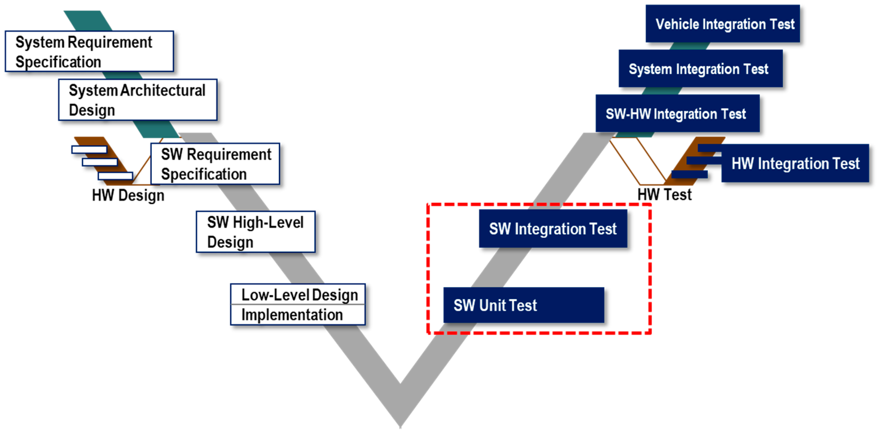
2.1. Fault Injection in the Development Process
2.2. AUTOSAR-Based Automotive Software Fault Injection Method
2.3. Fault Types in Automotive Software
3. AUTOSAR-Based Automotive Software Faults
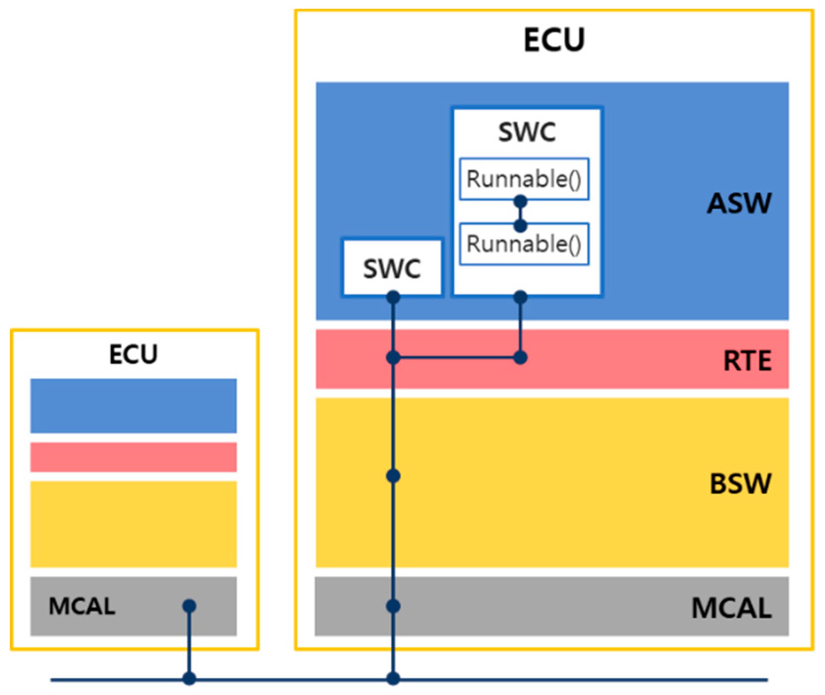
3.1. Calling Relationships between AUTOSAR Software Layers
- SW–SW calling relationships:
- ○
- Call between runnables within an SWC;
- ○
- Call between SWC and RTE;
- ○
- Call between SWC and BSW;
- ○
- Call between RTE and BSW.
- SW–HW calling relationships:
- ○
- Call between BSW and MCAL.
- HW–HW calling relationships:
- ○
- Call between drivers within MCALs.
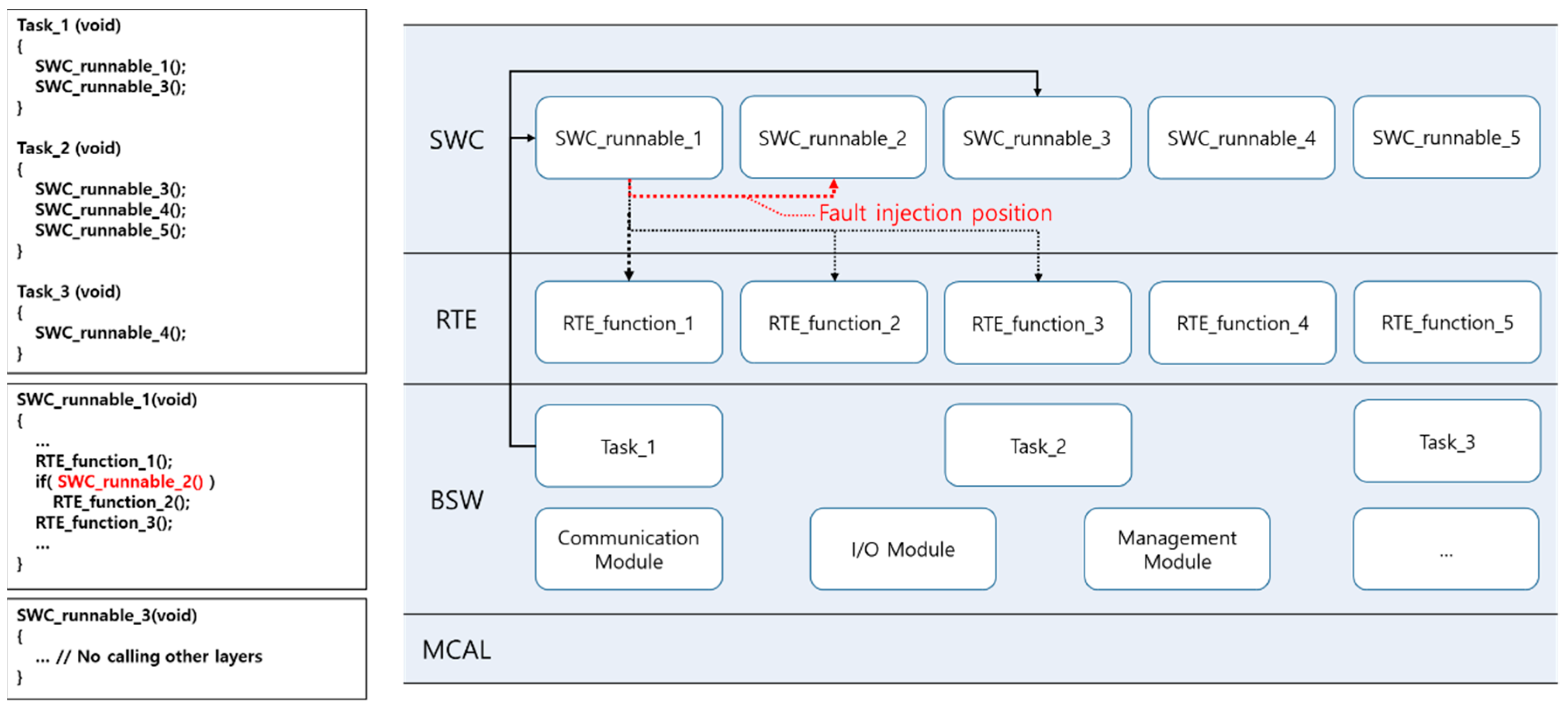
3.2. Fault Injection Position
- SW unit test step:
- ○
- Global variables used in the SWC runnable.
- SW integration test step:
- ○
- Calling function (caller) in the calling relationship between layers: function call parameter and call statement itself;
- ○
- Called function (callee): parameter received from the caller, variables used inside callee, and return statement.
3.3. Fault Types
3.4. AUTOSAR-Based Automotive Software Faults
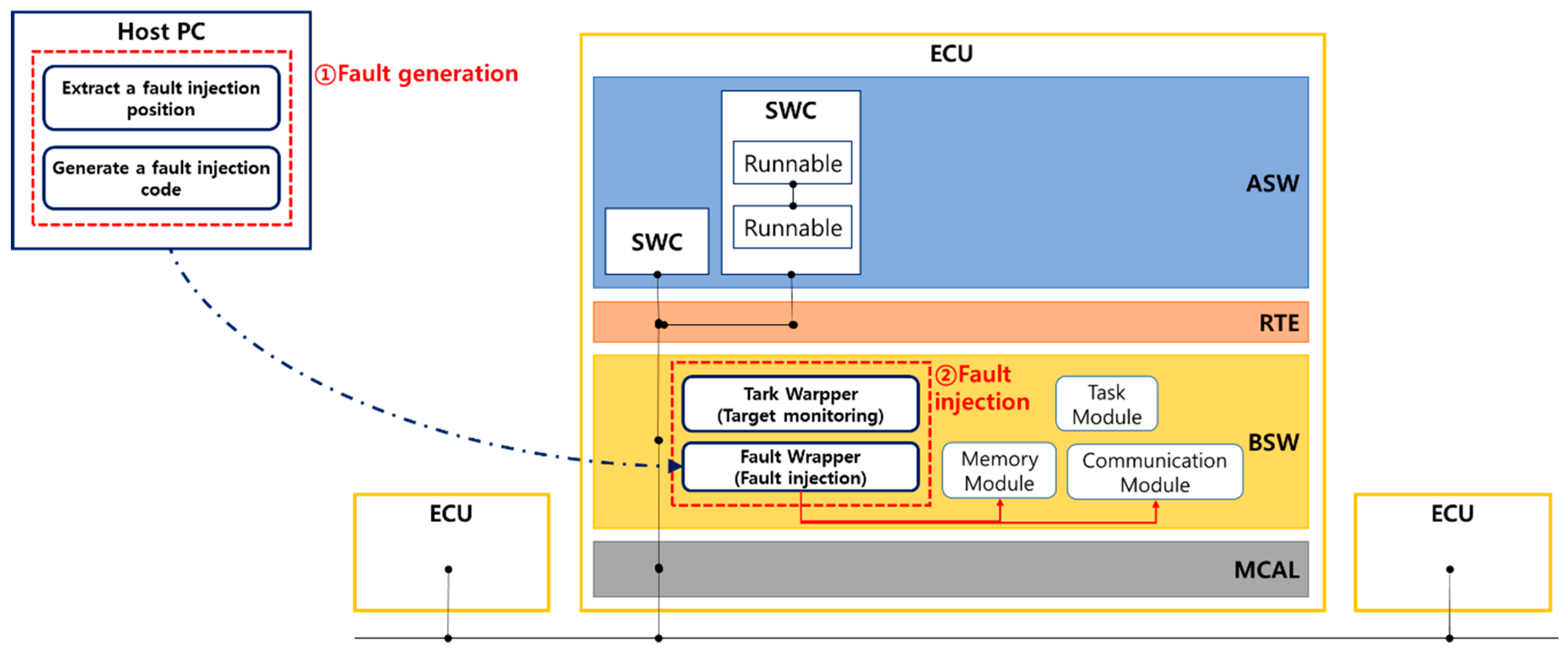
4. ASFIT: AUTOSAR-Based Automotive Software Fault Injection Method
4.1. Extraction of a Fault Injection Position
- Runnables inside SWC;
- Tasks allocated to each runnable;
- Global variables used in the runnables;
- Runnables in the calling relationships (runnable–runnable, runnable (SWC)–RTE, runnable (SWC)–BSW) or prototypes of functions (parameter, return value).
4.2. Generating the Fault Injection Code
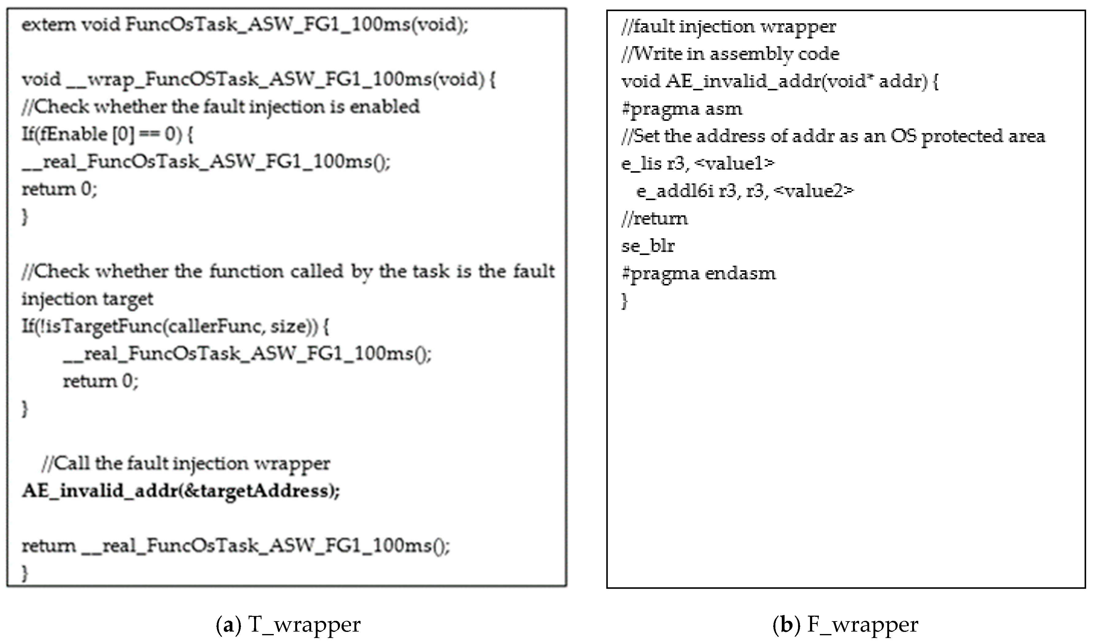
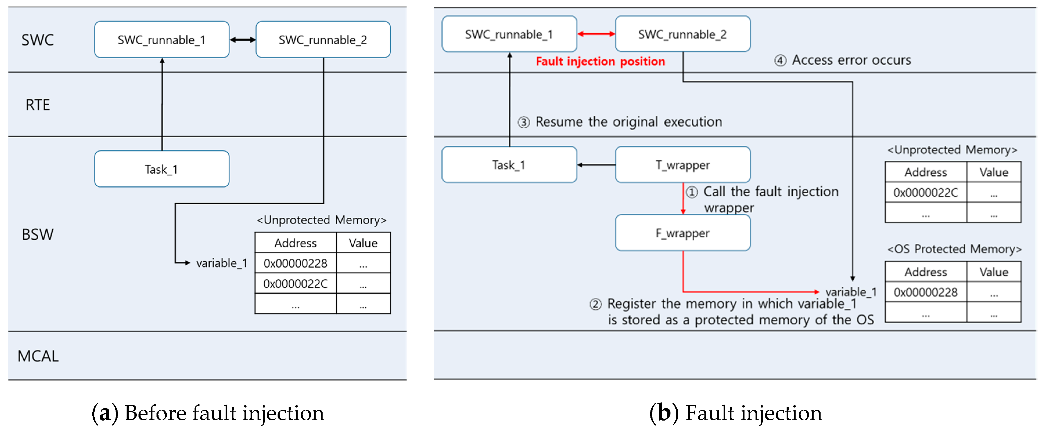
4.3. T_Wrapper
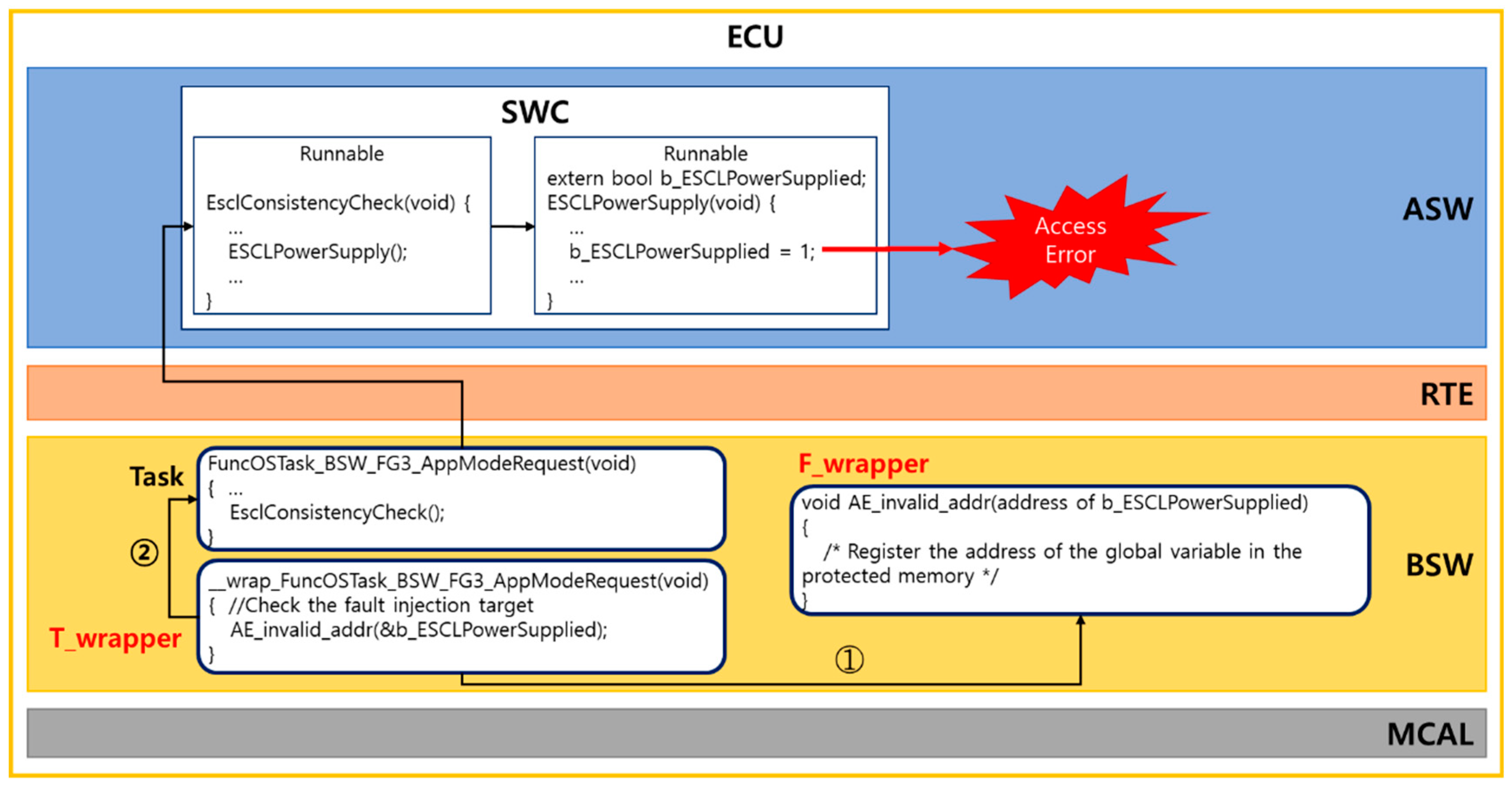
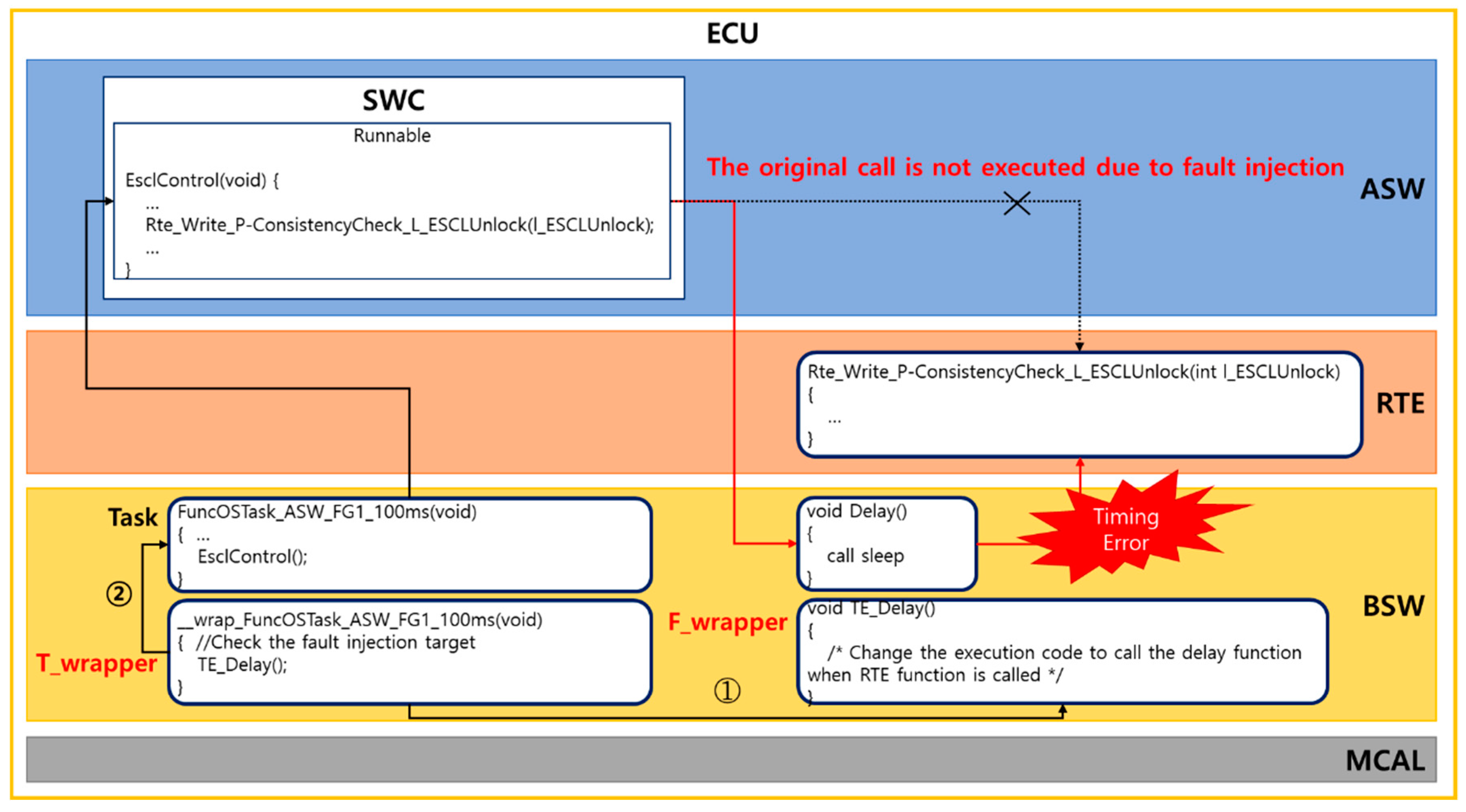
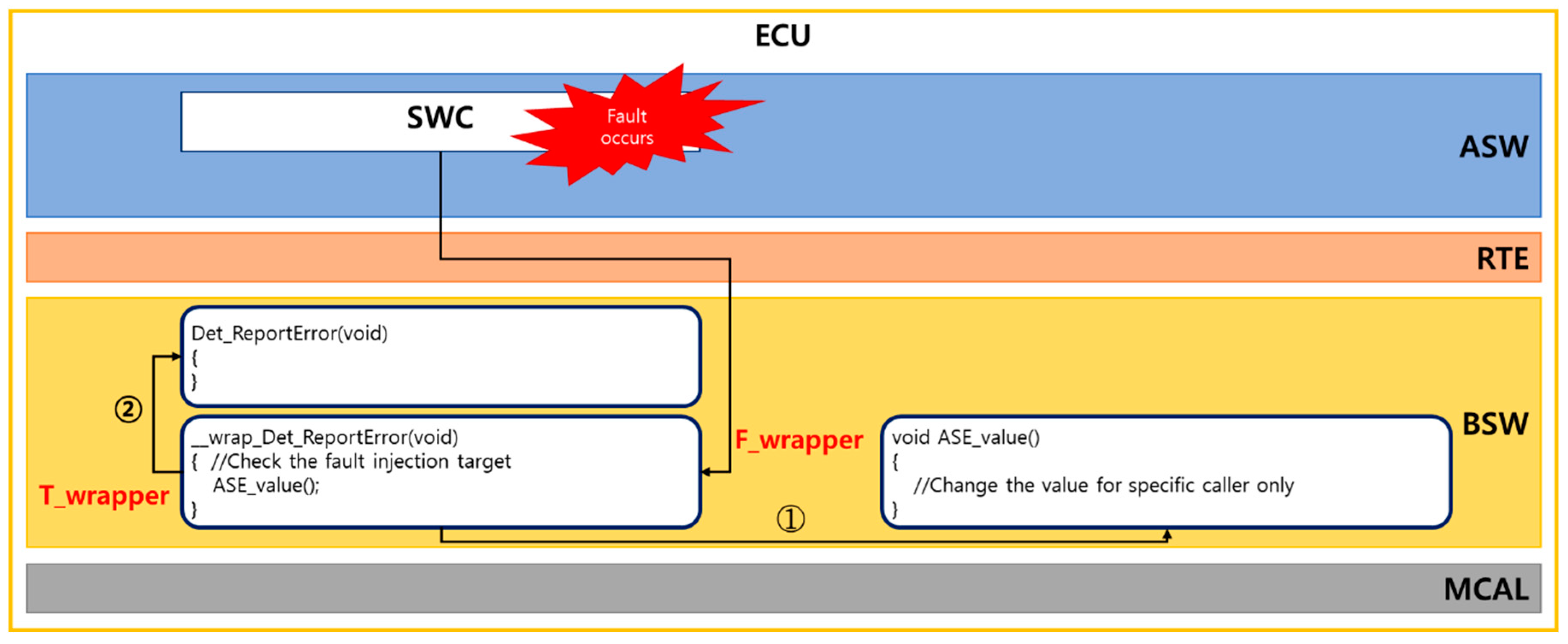
4.4. F_Wrapper
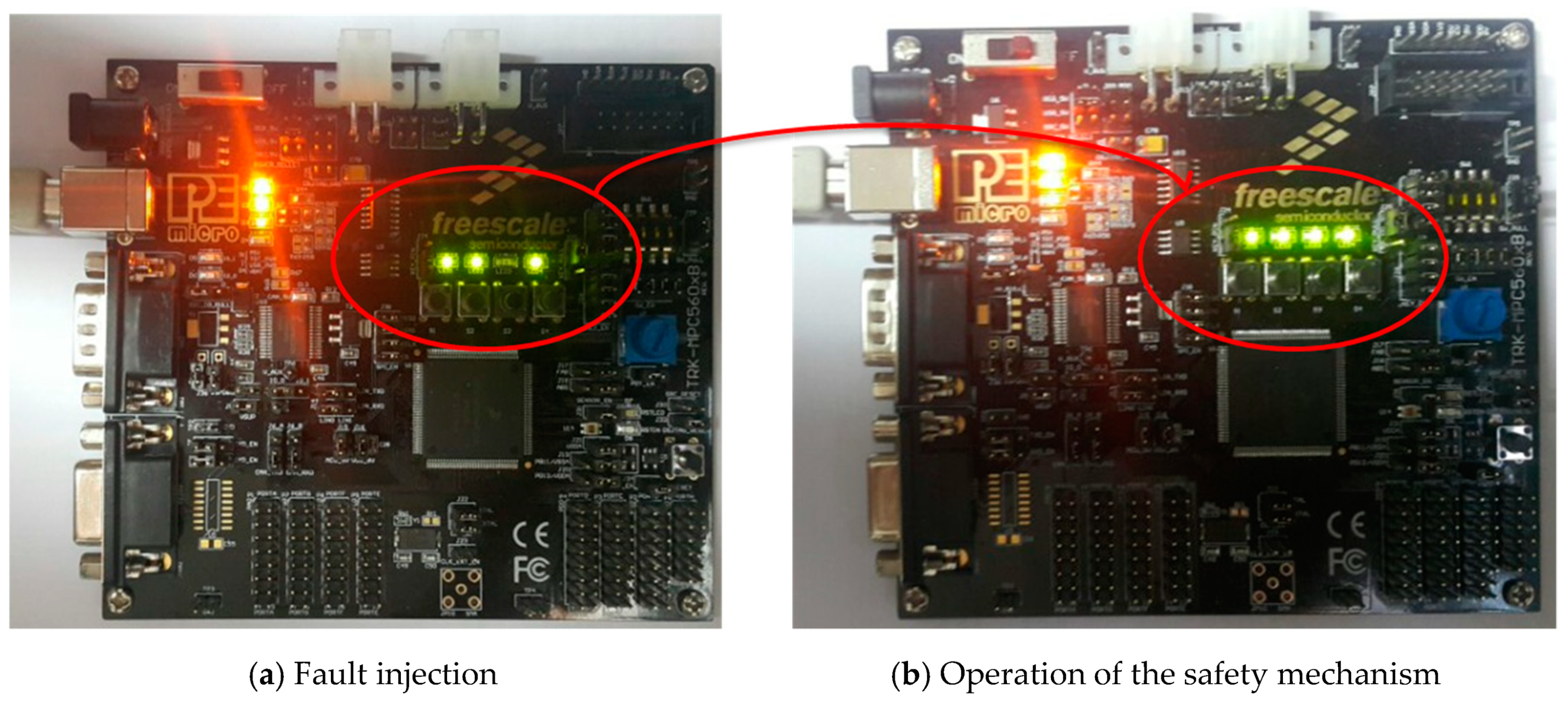
5. Empirical Study
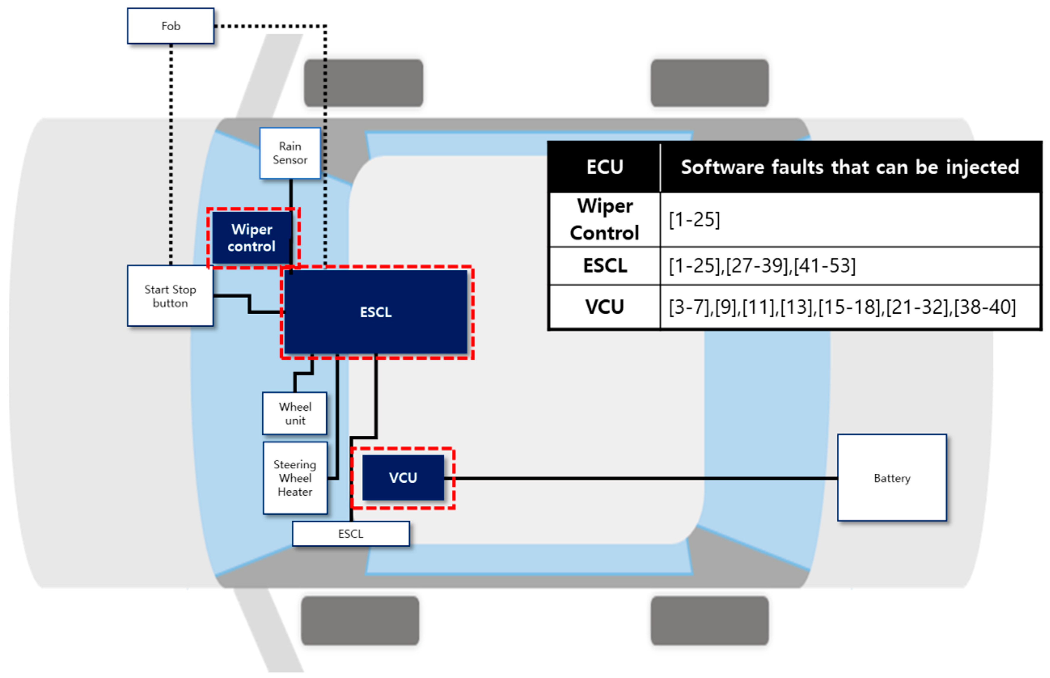
5.1. Experiment Design
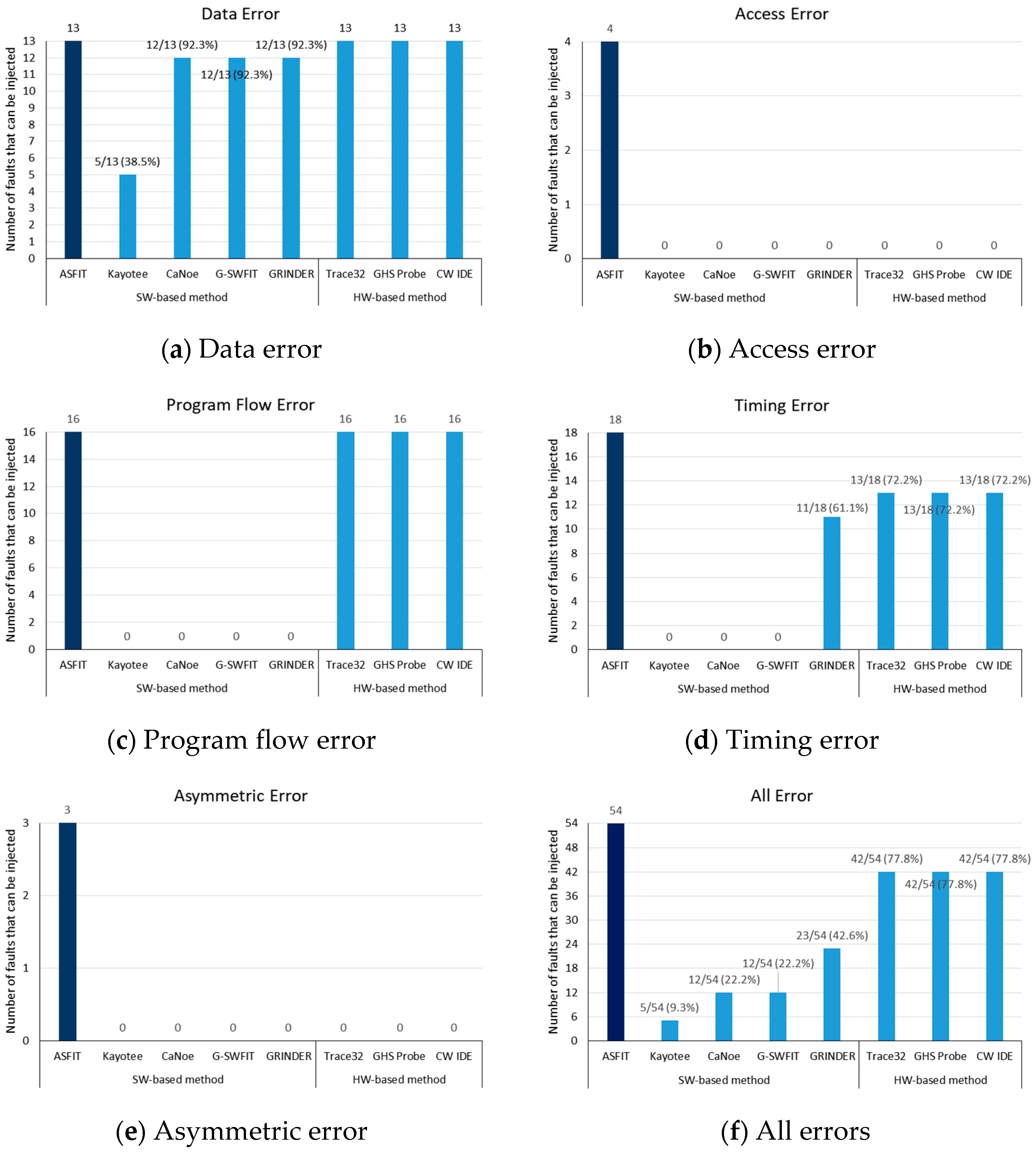
5.2. Experiment Results
5.3. Analysis
6. Runtime Overhead
6.1. Measuring the Runtime Overhead
6.2. Performance Measurement Results
7. Conclusions and Future Research
Author Contributions
Funding
Conflicts of Interest
References
- Rana, R.; Staron, M.; Berger, C.; Hansson, J.; Nilsson, M.; Törner, F. Increasing Efficiency of ISO 26262 Verification and Validation by Combining Fault Injection and Mutation Testing with Model based Development. In Proceedings of the International Conference on Software Engineering and Applications, Reykjavik, Iceland, 29–31 July 2013. [Google Scholar]
- ISO 26262–2011. Road vehicles-Functional Safety-Part 1–10. 2011. Available online: https://www.iso.org/standard/43464.html (accessed on 1 December 2017).
- Hsueh, M.C.; Tsai, T.K.; Iyer, R.K. Fault injection techniques and tools. Computer 1997, 30, 75–82. [Google Scholar] [CrossRef]
- Han, S.; Shin, K.G.; Rosenberg, H.A. Doctor: An integrated software fault injection environment for distributed real-time systems. In Proceedings of the 1995 IEEE International Computer Performance and Dependability Symposium, Erlangen, Germany, 24–26 April 1995; pp. 204–213. [Google Scholar]
- Fürst, S.; Mössinger, J.; Bunzel, S.; Weber, T.; Kirschke-Biller, F.; Heitkämper, P.; Kinkelin, G.; Nishikawa, K.; Lange, K. AUTOSAR—A Worldwide Standard is on the Road. In Proceedings of the 14th International VDI Congress Electronic Systems for Vehicles, Baden-Baden, Germany, 7–8 October 2009. [Google Scholar]
- Meng, X.; Tan, Q.; Shao, Z.; Zhang, N.; Xu, J.; Zhang, H. SEInjector: A dynamic fault injection tool for soft errors on x86. In Proceedings of the 2017 International Conference on Computer Systems, Electronics and Control (ICCSEC), Dalian, China, 25–27 December 2017; pp. 1492–1495. [Google Scholar]
- Skarin, D.; Barbosa, R.; Karlsson, J. GOOFI-2: A tool for experimental dependability assessment. In Proceedings of the 2010 IEEE/IFIP International Conference on Dependable Systems & Networks (DSN), Chicago, IL, USA, 28 June–1 July 2010; pp. 557–562. [Google Scholar]
- Madeira, H.; Rela, M.; Moreira, F.; Silva, J.G. RIFLE: A general purpose pin-level fault injector. In Proceedings of the European Dependable Computing Conference, Berlin, Germany, 4–6 October 1994; pp. 197–216. [Google Scholar]
- Jha, S.; Tsai, T.; Hari, S.; Sullivan, M.; Kalbarczyk, Z.; Keckler, S.W.; Iyer, R.K. Kayotee: A fault injection-based system to assess the safety and reliability of autonomous vehicles to faults and errors. arXiv Prepr 2019, arXiv:1907.01024. [Google Scholar]
- Lanigan, P.E.; Narasimhan, P.; Fuhrman, T.E. Experiences with a CANoe-based fault injection framework for AUTOSAR. In Proceedings of the 2010 IEEE/IFIP International Conference on Dependable Systems & Networks (DSN), Chicago, IL, USA, 28 June–1 July 2010; pp. 569–574. [Google Scholar]
- Duraes, J.; Madeira, H. Emulation of software faults: A field data study and a practical approach. IEEE Trans. Softw. Eng. 2006, 32, 849–867. [Google Scholar] [CrossRef]
- Winter, S.; Piper, T.; Schwahn, O.; Natella, R.; Suri, N.; Cotroneo, D. GRINDER: On reusability of fault injection tools. In Proceedings of the 2015 IEEE/ACM 10th International Workshop on Automation of Software Test, Florence, Italy, 23–24 May 2015; pp. 75–79. [Google Scholar]
- Islam, M.M.; Karunakaran, N.M.; Haraldsson, J.; Bernin, F.; Karlsson, J. Binary-Level Fault Injection for AUTOSAR Systems (Short Paper). In Proceedings of the 2014 Tenth European Dependable Computing Conference, Newcastle, UK, 13–16 May 2014; pp. 138–141. [Google Scholar]
- Barr, M. Bookout vs. Toyota: 2005 Camry L4 Software Analysis. District Court of Oklahoma County. 2013. Available online: http://www.safetyresearch.net/Library/BarrSlides_final_scrubbed.pdf,consultadoel,10 (accessed on 28 April 2020).
- Agrawal, H.; DeMillo, R.A.; Hathaway, B.; Hsu, W.; Hsu, W.; Krauser, E.W.; Martin, R.J.; Mathur, A.P.; Spaord, E. Design of Mutant Operators for C Programming Language; Technical Report SERC-TR-41-P, SERC; Purdue University: West Lafayette, IN, USA, 1989. [Google Scholar]
- Delamaro, M.E.; Maidonado, J.C.; Mathur, A.P. Interface mutation: An approach for integration testing. IEEE Trans. Softw. Eng. 2001, 27, 228–247. [Google Scholar] [CrossRef]
- Ghosh, S.; Mathur, A.P. Interface mutation. Softw. Test. Verif. Reliab. 2001, 11, 227–247. [Google Scholar] [CrossRef]
- AUTOSAR. “Explanation of Error Handling on Application Level,” AUTOSAR, Munich. 2009. Available online: https://www.autosar.org/fileadmin/user_upload/standards/classic/4-0/AUTOSAR_EXP_ApplicationLevelErrorHandling.pdf (accessed on 28 April 2020).
- MDS Technology. Trace32 Debugger. Available online: http://www.mdstec.com/ (accessed on 28 April 2020).
- Green Hills Software. GreenHills Debug Probes. Available online: http://www.ghs.com/ (accessed on 28 April 2020).
- Metrowerks. CodeWarrior IDE. Available online: http://www.nxp.com/ (accessed on 28 April 2020).


| AUTOSAR Application Error Type | SWFIT Faults | ||
|---|---|---|---|
| Fault Type | Description | ||
| Data error | Fault caused by invalid values of a parameter, variable, or message | Invalid value | Data error |
| Program flow error | Program running differently from what is expected due to omitted/invalid/unnecessary operations | Uncalled function | Uncalled function |
| Bypass function call | Bypass function call | ||
| Illegal instruction | Running an invalid command | ||
| Access error | Fault generated when an SW component attempts to accesses resources for which it has no permission | Invalid address | Accessing an invalid address |
| Invalid register | Accessing an invalid register | ||
| Timing error | Fault caused by early or late delivery or omission of a message | Data delay | Delay of data transmission |
| Data loss | Data loss during transmission | ||
| No response | No response | ||
| CPU clock corruption | CPU clock error | ||
| Asymmetric error | Fault generated by delivery of different values when multiple components receive messages simultaneously | Asymmetric value | Receiving asymmetric data |
| Test Step | Fault Injection Position | Software Fault | Fault ID | ||||
|---|---|---|---|---|---|---|---|
| SW unit test | Runnable | Variables | Global variable | Data error | Invalid value | 1 | |
| SW integration test | SW–SW integration test | Runnable-Runnable | Caller | Parameter | Data error | Invalid value | 2 |
| Call statement itself | Program flow error | Uncalled function | 3 | ||||
| Bypass function call | 4 | ||||||
| Illegal instruction | 5 | ||||||
| Callee | Global variable | Data error | Invalid value | 6 | |||
| Access error | Invalid address | 7 | |||||
| Return statement | Data error | Invalid value | 8 | ||||
| Program flow error | Illegal instruction | 9 | |||||
| Timing error | Data error | 10 | |||||
| CPU clock corruption | 11 | ||||||
| SWC–RTE | Caller | Parameter | Data error | Invalid value | 12 | ||
| Timing error | Data delay | 13 | |||||
| Data loss | 14 | ||||||
| Call statement itself | Program flow error | Uncalled function | 15 | ||||
| Bypass function call | 16 | ||||||
| Illegal instruction | 17 | ||||||
| Timing error | CPU clock corruption | 18 | |||||
| Callee | Global variable | Data error | Invalid value | 19 | |||
| Access error | Invalid address | 20 | |||||
| Return statement | Data error | Invalid value | 21 | ||||
| Program flow error | Illegal instruction | 22 | |||||
| Timing error | Data loss | 23 | |||||
| No response | 24 | ||||||
| CPU clock corruption | 25 | ||||||
| Asymmetric error | Asymmetric value | 26 | |||||
| SWC–BSW | Caller | Parameter | Data error | Invalid value | 27 | ||
| Timing error | Data delay | 28 | |||||
| Call statement itself | Program flow error | Uncalled function | 29 | ||||
| Bypass function call | 30 | ||||||
| Illegal instruction | 31 | ||||||
| Timing error | CPU clock corruption | 32 | |||||
| Callee | Global variable | Data error | Invalid value | 33 | |||
| Access error | Invalid address | 34 | |||||
| Return statement | Data error | Invalid value | 35 | ||||
| Program flow error | Illegal instruction | 36 | |||||
| Timing error | Data loss | 37 | |||||
| No response | 38 | ||||||
| CPU clock corruption | 39 | ||||||
| Asymmetric error | Asymmetric value | 40 | |||||
| SW–HW integration test | SWC–ECUHW | Caller | Parameter | Data error | Invalid value | 41 | |
| Timing error | Data delay | 42 | |||||
| Call statement itself | Program flow error | Uncalled function | 43 | ||||
| Bypass function call | 44 | ||||||
| Illegal instruction | 45 | ||||||
| Timing error | CPU clock corruption | 46 | |||||
| Callee | Global variable | Data error | Invalid value | 47 | |||
| Access error | Invalid address | 48 | |||||
| Return statement | Data error | Invalid value | 49 | ||||
| Program flow error | Illegal instruction | 50 | |||||
| Timing error | Data loss | 51 | |||||
| No response | 52 | ||||||
| CPU clock corruption | 53 | ||||||
| Asymmetric error | Asymmetric value | 54 | |||||
| Layer Using Wrapper | Description | Calling Relationships in Which Faults Can Be Injected | Fault Types That Can Be Injected |
|---|---|---|---|
| SWC | The SWC layer provides various services that run in automotive SW. The wrapper function injects faults in runnables or functions of the SWC layer. |
|
|
| RTE | The RTE layer is an interface that connects the SWC and BSW layers. The wrapper function injects faults in functions of the RTE layer. |
|
|
| BSW (our method) | The BSW layer performs service execution control, memory management, and device management. The wrapper function injects faults in functions of the BSW layer. |
|
|
| Fault Injection Method | |
|---|---|
| SW-based method | ASFIT |
| Kayotee [9] | |
| CaNoe-based FIT [10] | |
| G-SWFIT [11] | |
| GRINDER [12] | |
| HW-based method | TRACE32 [19] |
| GreenHills Debug Probes (hereinafter, GHS Probe) [20] | |
| Code Warrior IDE (hereinafter, CW IDE) [21] | |
| Fault Injecting Method | Software Fault ID | # | ||||||||||||||||||
|---|---|---|---|---|---|---|---|---|---|---|---|---|---|---|---|---|---|---|---|---|
| 1 | 2 | 3 | 4 | 5 | 6 | 7 | 8 | 9 | 10 | 11 | 12 | 13 | 14 | 15 | 16 | 17 | 18 | 54 | ||
| 19 | 20 | 21 | 22 | 23 | 24 | 25 | 26 | 27 | 28 | 29 | 30 | 31 | 32 | 33 | 34 | 35 | 36 | |||
| 36 | 38 | 39 | 40 | 41 | 42 | 43 | 44 | 45 | 46 | 47 | 48 | 49 | 50 | 51 | 52 | 53 | 54 | |||
| SW-based method | ASFIT | o | o | o | o | o | o | o | o | o | o | o | o | o | o | o | o | o | o | 54 |
| o | o | o | o | o | o | o | o | o | o | o | o | o | o | o | o | o | o | |||
| o | o | o | o | o | o | o | o | o | o | o | o | o | o | o | o | o | o | |||
| Kayotee | o | x | x | x | x | o | x | x | x | x | x | o | x | x | x | x | x | x | 5 | |
| x | x | x | x | x | x | x | X | o | x | x | x | x | x | x | x | x | x | |||
| x | x | x | x | o | x | x | x | x | x | x | x | x | x | x | x | x | x | |||
| CaNoe | x | o | x | x | x | o | x | o | x | x | x | o | x | x | x | x | x | x | 12 | |
| o | x | o | x | x | x | x | x | o | x | x | x | x | x | o | x | o | x | |||
| x | x | x | x | o | x | x | x | x | x | o | x | o | x | x | x | x | x | |||
| G-SWFIT | x | o | x | x | x | o | x | o | x | x | x | o | x | x | x | x | x | x | 12 | |
| o | x | o | x | x | x | x | x | o | x | x | x | x | x | o | x | o | x | |||
| x | x | x | x | o | x | x | x | x | x | o | x | o | x | x | x | x | x | |||
| GRINDER | x | o | x | x | x | o | x | o | x | o | x | o | o | o | x | x | x | x | 23 | |
| o | x | o | x | o | o | x | x | o | o | x | x | x | x | o | x | o | x | |||
| o | o | x | x | o | o | x | x | x | x | o | x | o | x | o | o | x | x | |||
| HW-based method | TRACE32 | o | o | o | o | o | o | x | o | o | o | o | o | x | o | o | o | o | o | 42 |
| o | x | o | o | o | x | o | x | O | x | o | o | o | o | o | x | o | o | |||
| o | x | o | x | o | x | o | o | o | o | o | x | o | o | o | o | o | x | |||
| GHS Probe | o | o | o | o | o | o | x | o | o | o | o | o | x | o | o | o | o | o | 42 | |
| o | x | o | o | o | x | o | x | o | x | o | o | o | o | o | x | o | o | |||
| o | x | o | x | o | x | o | o | o | o | o | x | o | o | o | o | o | x | |||
| Code Warrior | o | o | o | o | o | o | x | o | o | o | o | o | x | o | o | o | o | o | 42 | |
| o | x | o | o | o | x | o | x | o | x | o | o | o | o | o | x | o | o | |||
| o | x | o | x | o | x | o | o | o | o | o | x | o | o | o | o | o | x | |||
© 2020 by the authors. Licensee MDPI, Basel, Switzerland. This article is an open access article distributed under the terms and conditions of the Creative Commons Attribution (CC BY) license (http://creativecommons.org/licenses/by/4.0/).
Share and Cite
Park, J.; Choi, B. ASFIT: AUTOSAR-Based Software Fault Injection Test for Vehicles. Electronics 2020, 9, 850. https://doi.org/10.3390/electronics9050850
Park J, Choi B. ASFIT: AUTOSAR-Based Software Fault Injection Test for Vehicles. Electronics. 2020; 9(5):850. https://doi.org/10.3390/electronics9050850
Chicago/Turabian StylePark, Jihyun, and Byoungju Choi. 2020. "ASFIT: AUTOSAR-Based Software Fault Injection Test for Vehicles" Electronics 9, no. 5: 850. https://doi.org/10.3390/electronics9050850
APA StylePark, J., & Choi, B. (2020). ASFIT: AUTOSAR-Based Software Fault Injection Test for Vehicles. Electronics, 9(5), 850. https://doi.org/10.3390/electronics9050850