1. Introduction
Terahertz imaging is a novel imaging method with promising application fields. Terahertz waves are electromagnetic waves with a wavelength between 30 and 3000 µm or a frequency between 0.1 and 10 THz. Terahertz waves have a low electron energy and a high penetration against dielectric materials, which make them applicable for see-through imaging for multiple materials such as plastic, ceramic, woods, papers and polymer composites [
1,
2,
3]. Compared with common see-through imaging methods such as X-ray, microwave and ultrasonic imaging, terahertz imaging has advantages in penetration, non-destructive and resolving power, which make it a promising and irreplaceable imaging method in multiple application fields, including industrial Non-Destructive Testing (NDT)—[
4,
5], heritage conservation [
6,
7,
8], aerospace [
9], security [
10,
11,
12], biology and medicine [
13].
Thanks to the fast development of terahertz source and detector component techniques, terahertz Focal Plane Array Detectors (FPA) based on a microbolometer [
14,
15] and complementary metal oxide semiconductor (CMOS) [
16,
17,
18,
19] make fast, large-scale, high-resolution, incoherent terahertz imaging methods available. However, passive mode imaging in the terahertz region is infeasible for the see-through applications mentioned above, as little background radiation in the terahertz region exists in the environment, and the method is still limited by the performance of commercially available devices [
20]. To ensure an acceptable signal-to-noise ratio (SNR) and resolve the power for samples with a certain thickness, most terahertz imaging applications rely on a high-power, collimated source for illumination [
3]. The beam of a high power continuous-wave (CW) terahertz source such as a gas-pumped laser and quantum cascade laser (QCL) is a Gaussian beam. When used in active illumination imaging, the wavefront characteristics of the Gaussian beam would lead to distortion, which significantly reduces the resolving power. A beam homogenizer would help in reducing such distortion; however, a beam homogenizer diffuses beam energy, which leads to negative impacts in transmission-type imaging applications that require a sufficiently effective imaging depth and concentrated beam energy. Moreover, the microbolometer and CMOS terahertz FPA have issues in terms of Fixed Pattern Noise (FPN) [
21,
22], which leads to adverse effects on the SNR and the resolving power of the imaging result.
An optical system with a larger aperture will help to solve the problems mentioned above. However, limited by the size of the system and the cost of processing, enlarging the aperture size is impracticable in most applications. Introducing the Light Field Imaging (LFI) method will help to solve this problem. LFI is an incoherent computational imaging method which extracts information from data of higher dimensions and achieves a better performance compared with conventional methods [
23]. In LFI, both the positional and directional information of the imaging object are gathered simultaneously, implementing enhancements in SNR, dynamic range, depth of field (DoF) and additional depth information about the images [
24] with reconstruction algorithms. In the visible region, light field acquisition methods based on microlens arrays [
24], camera arrays [
25], and coded aperture compressive sensing [
26] are now being widely studied. Moreover, the LFI technique is also utilized in multiple applications including dynamic refocusing [
24], DoF extension [
27], all-in-focus reconstruction [
28], depth estimation [
29,
30], 3D reconstruction [
31], super-resolution reconstruction [
32,
33], synthetic aperture imaging and high-speed photography [
27].
Jain et al. [
34] proved the feasibility of LFI in the terahertz waveband with a simplified experimental setup. In their experiments, the LFI of a point source and simple opaque object was implemented with a camera module of a low angular (approximately 1.5°) and spatial (approximately 28 mm) resolution. In their study, the effects caused by the coherence of light sources and the aperture of the imaging system are not further discussed, which are important factors for practical imaging systems and objects. In fact, these effects cause the main differences in the image characteristics between the terahertz and visible region.
In this paper, a novel, incoherent synthetic aperture terahertz imaging method based on the LFI technique is demonstrated, and the performance improvements of the new method are validated. The phenomenon of image distortion happening in the terahertz imaging system with Gaussian beam illumination has been investigated. With microbolometer-based terahertz FPA detectors and a high-power gas-pumped terahertz source, a terahertz virtual camera array LFI system has been established. With the experiments of transmission-type imaging configuration, the effectiveness of the LFI method in removing the image distortion and improving the resolving power compared with a conventional setup is validated.
2. Theory and Methods
2.1. Light Field Theory and Mathematical Model
The plenoptic model is a model used to describe the “light field”, i.e., the spatial propagation of light flowing. In particular, in the plenoptic model, the light flow is simplified as sizeless “rays”, described by their position and direction and by the plenoptic function. Assuming that the rays emitted by light sources do not spatially overlap, the positional and directional information of light rays can be described using four dimensions.
In the case of a two-plane scheme, a 4D light field can be described with a 4D plenoptic function , which describes rays with the intersectional coordinates of two parallel planes.
Specifically, two planes
and
are defined with a fixed distance, and the rays will intersect with two lanes. The combination of all the rays passing through every coordinate on planes
and
create the full light field, as shown in
Figure 1. The two-plane scheme is introduced for practical light field acquisition methods. For any combination of two dimensions in the 4D plenoptic function, for example, rays intersect with a certain
or certain
coordinate—we call this a 2D slice of the 4D plenoptic function. In practice, the “slice” is used to describe the sub-aperture images, macro-pixels or epipolar images of 4D light fields.
The procedure of LFI can be divided into two steps: the acquisition and the reconstruction. The acquisition phase physically gathers and resolves the 4D light field of the object, and the reconstruction phase generates enhanced images with the acquired 4D light field information.
2.2. The Acquisition of the 4D Light Field
Compared with conventional imaging, the acquisition of the 4D light field initiates both positional and directional resolution simultaneously, namely the resolving of individual light rays. Imagine an FPA imaging system, or “camera”: light rays are focused by optic systems (called the main aperture) at the
uv plane, then gathered, resolved and imaged by detector pixels at the
xy plane. The pixels are the partitions of
xy planes. The light signal received by pixels corresponds to the sum of light rays emitted from a certain position in all directions (which can be gathered by the main aperture). The light signal received by pixels is converted into images. We perform the same partition on the
uv plane, and the partition on the
uv plane is called a “sub-aperture”. The lightbeams illuminated on a single pixel through the single sub-aperture could be approximately regarded as rays in the plenoptic model. Rays correspond to the partition of light emitted by a certain point source along a certain direction. In this case, besides the image plane in the image space, the conjugated plane of the
xy plane in the object space can be regarded as the
xy plane as well, after a simple coordinate transformation, as shown in
Figure 2a.
For an FPA imaging system, when the imaging distance is long enough, relative to the focal length, the size of the aperture can be ignored, and the whole beam focused on a single pixel through the aperture can be regarded as an individual ray. Thus, the image recorded by the detector array can be regarded as a combination of rays in certain positions and different directions, namely a 2D slice of the 4D light field. Arranging such cameras on the
uv plane, the full light field can be recorded by recording all of its sub-aperture slices. With this camera array, the 4D light field can be acquired with a synthetic aperture equivalent to the size of the camera array, and its resolution depends on the resolution and spacing of the camera modules. In this case, the
xy plane does not really exist in the image space, since there is no common image space for every single camera. Besides this, the common plane conjugated to image planes of all cameras (supposing they are regularly arranged and have the same optical parameters) in the object space is regarded as the
xy plane, as shown in
Figure 2b. In practice, the light field slices are acquired with a camera array consisting of multiple FPA cameras, or a virtual camera array for static light fields, with a limited number of cameras.
2.3. Light Field Reconstruction
The reconstruction of a 4D light field is a simulation of the focusing and imaging procedures of the optical imaging system in a geometric optic manner, based on the 4D light field information.
For a given 4D light field LF(x,y,u,v), the planes, uv, xy, and the distance F between planes uv and xy are given.
When replacing the plane
xy with the plane
x′y′ in the description, where the distance from plane
uv is
z = αF, the transformed plenoptic function could be described as
which is equal to shearing the plenoptic function in
xy dimensions. The ray passing through the point (
x0,
y0,
z) in space and the point (
u,
v,0) on the plane
uv could be described as
Substituting the deferent points (
u,v) in Equation (2) gives us the combination of the rays passing through the point (
x0, y0, z). Assuming we know the depth
z(
x0, y0) of all points
. in the scene, the Equation (2) could be transformed into
and the reconstructed image could be described as
As mentioned in
Section 2.2, in practical light field acquisition, the 4D light field is discretized into pixels in all
xyuv dimensions, and the slices of the light field in
uv and
xy dimensions are discretized into the 2D combination of pixels as well. Therefore, in the practical implementation of the reconstruction algorithm, the continuous integration in Equation (3) is transformed into the numerical sum of discretized pixels. For every discretized pixel (
x0,y0) in the reconstructed image, the algorithm traverses all the slices (
u,v) of the light field, searches for the pixels corresponding to the ray through (
u,v), (
x′,y′) and (
x0,y0), and calculates the pixel values from all the slices.
If the input light field is from a single physical aperture, the algorithm simply simulates the imaging procedure in geometric optics and generates reconstructed images as a result. If the input light field is from the camera array described in
Section 2.2, the algorithm generates reconstructed images based on a synthetic aperture.
3. Experiment and Result
3.1. Distortion Analysis of Gaussian Beam Active Illuminated Terahertz Imaging
In this section, the phenomenon of the image distortion observed in the active illuminated terahertz imaging process will be discussed.
In our experiment, a transmission-type terahertz imaging system based on Gaussian beam active illumination and an FPA terahertz camera has been established. In particular, the terahertz beam from the source is collimated by a Teflon collimation lens, transmitted through the object, and then received by the camera at different positions. In the experiment, the object and the source are fixed. The camera moves around and acquires images at different positions. The camera remains static when acquiring images to avoid motion blur. The experimental setup is shown in
Figure 3.
In the experiment, a Coherent SIFIR–50 gas-pumped continuous-wave terahertz source is used as an illumination source. The terahertz source works at 2.52 THz, and the output power is about 50 mW, which provides a stable and good SNR performance. An INO IRXCAM-THz–384 terahertz camera module is used to acquire terahertz images. The camera uses FPA detectors based on uncooled microbolometers, with a 35 µm pixel size and a resolution of 384 × 288 pixels, and is capable of capturing images at a 50 fps rate. The camera module has Silicon imaging optics, with a 44-mm focal length, a field of view of about 17.3 × 13.0 degrees, and a spatial resolution of about 0.5 mm. In the experiment, an extra Teflon filter is mounted in front of the camera module to filter the unwanted infrared signal in the environment.
The imaging object of the experiment is a polypropylene composite Pelican case with bumped markings. The thickness of the case is about 4 mm, and the diameter and thickness of the bumped markings are about 5 mm and 0.2 mm, respectively, as shown in
Figure 4. In the experiment, the distance between the source and the object is 2000 mm, and the distance between the object and the camera is 600 mm.
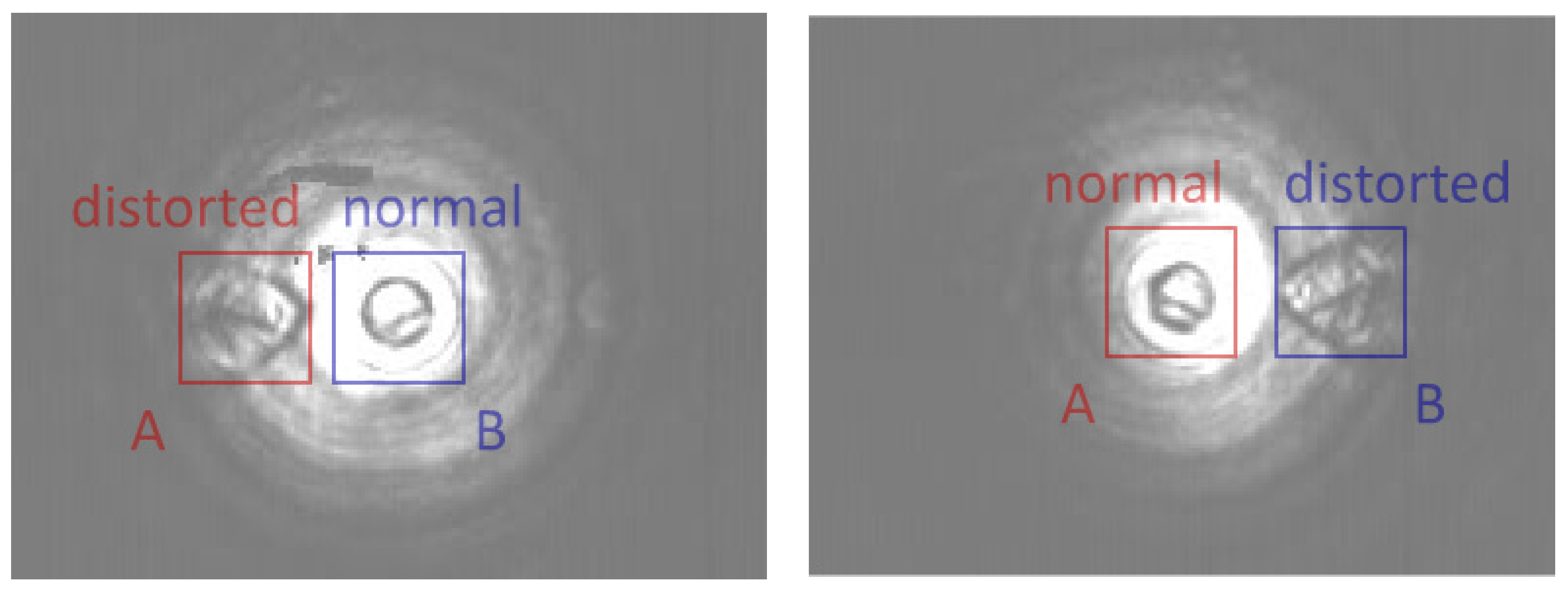
Figure 5 is the image acquired by the camera when in different positions. For active illuminated imaging, when using a point source or collimated beam for illumination, only a portion of the beam that passes through both the object and the aperture contributes to the imaging result. This portion of the “effective” beam corresponds to a “bright spot” or “bright circle” in the terahertz image. Refraction and total reflection occur at the edges of the bumped markings, which results in a significant contrast in the acquired terahertz images.
Ideally, the round bumped markings should be the same shape in the terahertz image as their original shapes. In the experiment, when located in the center of the spot, the markings are imaged correctly as a circle. However, when located near the edge of the spot, the markings are significantly distorted and appear to be drop-shaped. The phenomenon of distortion does not occur when illuminated by a planar homogenized source or incoherent sources in the infrared waveband. In practical applications, this distortion will significantly affect the resolving power of the imaging.
3.2. Resolving Power Analysis of Terahertz LFI Setup
In this section, compared with conventional transmission-type imaging, the improvement of terahertz LFI on the resolving power and image distortion mentioned in
Section 3.1 will be discussed.
Based on the transmission-type terahertz imaging system mentioned in
Section 3.1, a terahertz LFI system has been established. A virtual camera array based on a terahertz camera module and motorized translation stages are utilized to replace the single terahertz camera, in order to acquire the full 4D light field.
The camera module is fixed on a 2D translation stage, which can move in both x and y directions vertical to the optical axis of the camera. The translation stages drive the camera and acquire the slices of the full light field in different positions.
In the experiment, the Coherent SIFIR–50 source works at the frequency of 1.40 THz, with an output power of about 84 mW, which provides a better penetration for the sample used in this part of the experiment. The experimental setup is shown in
Figure 6.
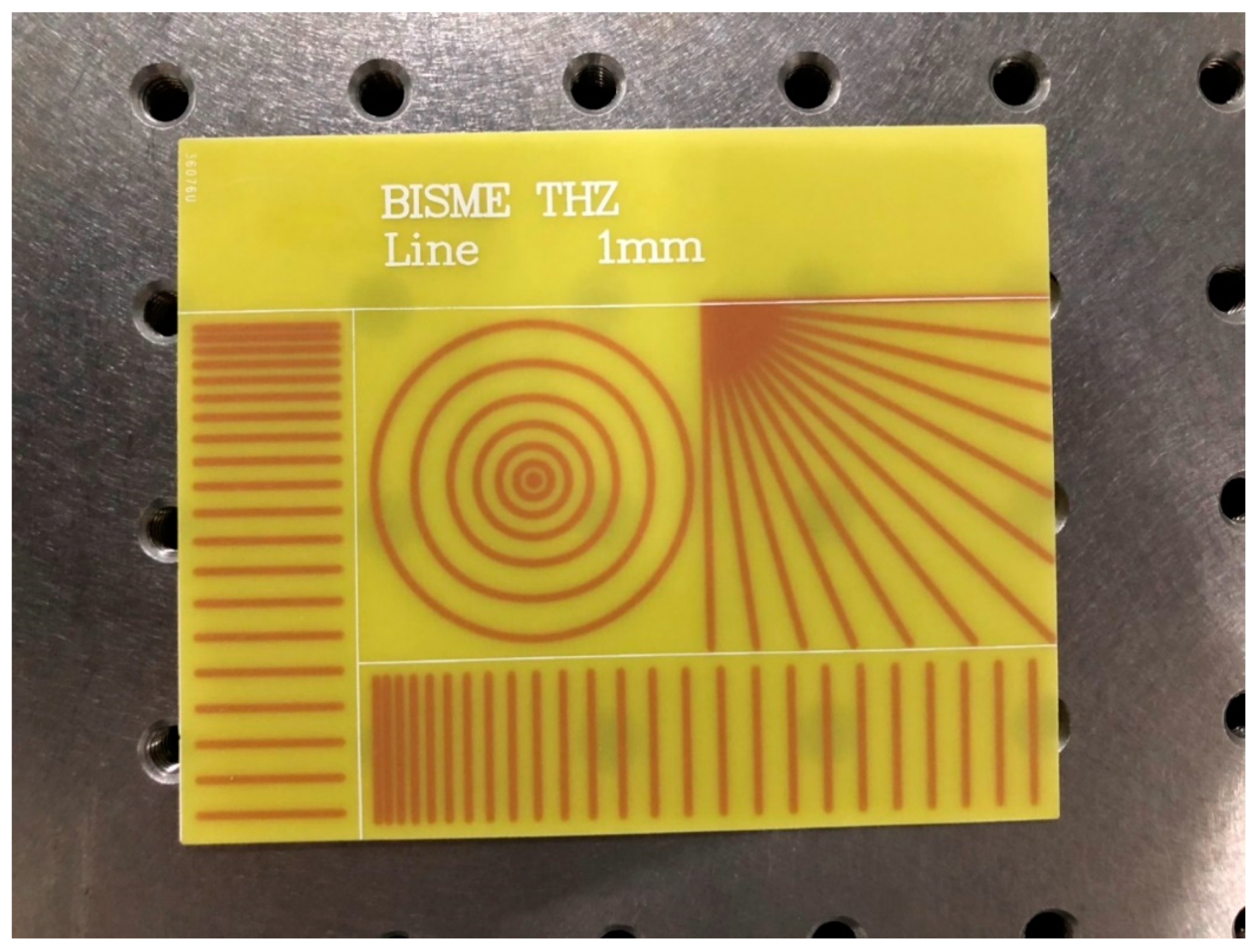
The imaging object is a resolving power test target with concentric circle and line pair patterns. The base material of the card is epoxy of 0.5 mm thickness, which is transparent to the terahertz wave. The concentric circle and line pair patterns are printed on the base with copper, which is opaque to the terahertz wave. The spacing between line pairs ranges from 0.125 mm to 3 mm, and the spacing between concentric circles ranges from 0.5 mm to 3 mm. The line widths of both line pairs and concentric circles are 1 mm, as shown in
Figure 7. In the light field acquisition, the number of sub images is 11 × 31 sub-images, and the spacing is 5 × 5 mm. The distance between the source and the object is 2000 mm, and the distance between the object and the camera is 600 mm.
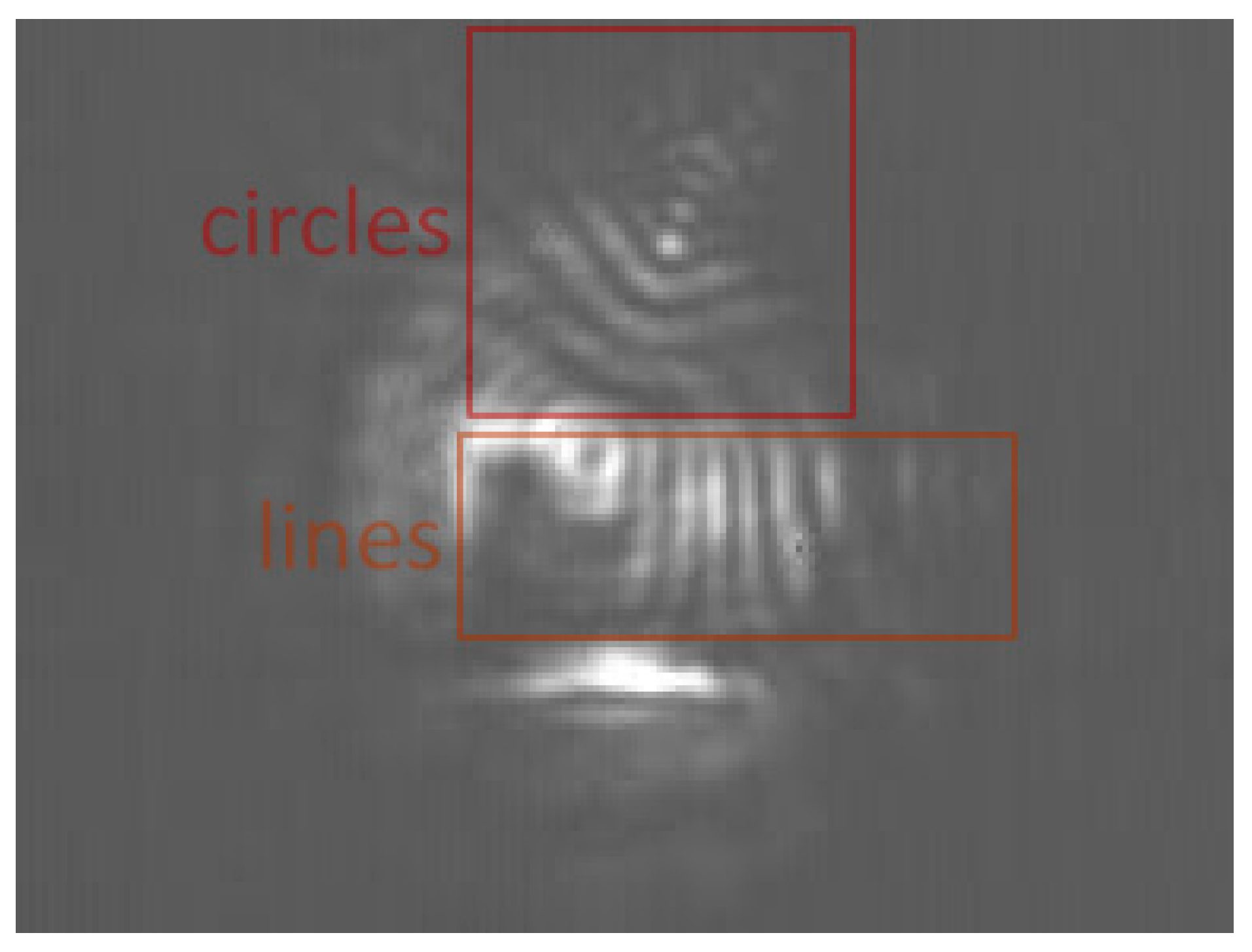
Figure 8 is one of the enlarged sub-aperture images; i.e., the imaging result of a single shot with a single camera. Compared with the results in
Section 3.1, the result of line pairs and concentric circles suffered a severe and irregular distortion, which significantly reduced the resolving power of the imaging system for the patterns and made the positions and spacing of lines and circles almost indistinguishable. Moreover, the interference fringes and fixed pattern noise of the detectors further reduced the performance of the imaging result.
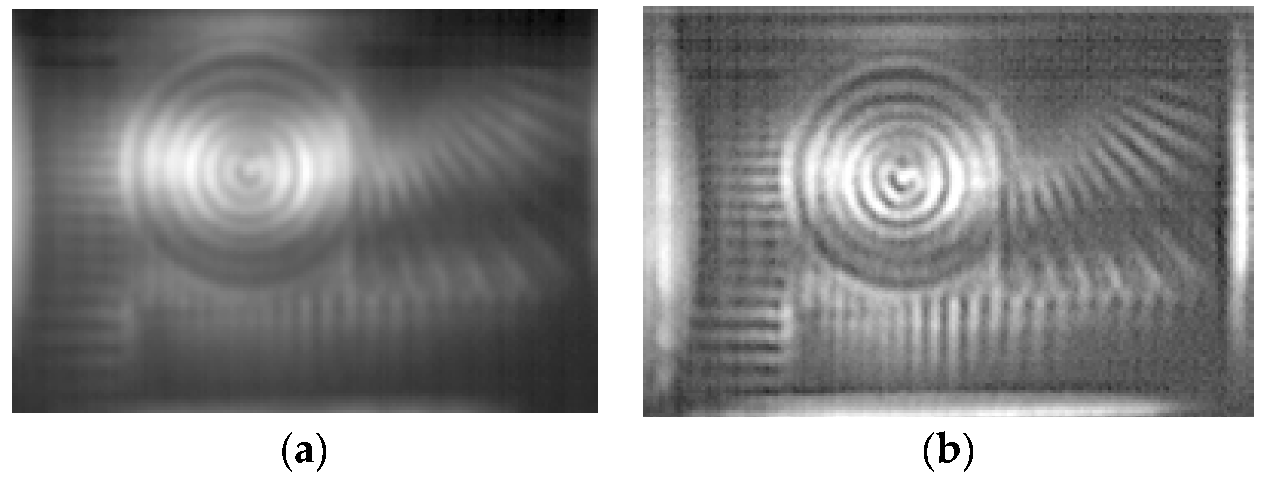
Figure 9a,b shows the results of the light field reconstruction.
Figure 9a is the result directly reconstructed by the 4D light field reconstruction algorithm, and
Figure 9b is the result further enhanced with the Unsharp Mask (USM) algorithm. In reconstructed light field images, the complete portions of the object are clearly imaged. The distortion is almost removed, and the line and circle patterns are clearly distinguishable. The interference fringes and FPN are significantly suppressed as well. In the directly reconstructed image, the fourth line and the first circle with a spacing of 0.5 mm are clearly distinguishable. In the USM-enhanced image, although the suppression of noise is weakened, the resolving power of patterns is increased, since the third line, with a spacing of 0.375 mm, becomes distinguishable. Compared with the result of the conventional method, the performance and resolving power are significantly improved by using the synthetic aperture method, and the unrecognizable patterns as a result of the conventional method become fully recognizable with the synthetic aperture method.
4. Conclusions
In this paper, an experimental transmission-type terahertz imaging system and a virtual camera array terahertz LFI system were established based on a high-power gas-pumped terahertz source and terahertz focal plane array detectors. On the one hand, the phenomenon of image distortion occurred in terahertz imaging, and its influences on resolving power have been observed and analyzed; on the other hand, a novel synthetic aperture method based on the LFI technique was introduced, and its improvement of image performance and suppression of image distortion were validated in the experiments carried out.
In the imaging experiment on a resolving power test target, the conventional method showed an unacceptable result, where the distortion made the line and circle patterns completely indistinguishable, while the synthetic aperture method with USM sharpening enhancement showed a much better result: the line pairs with less than 0.5 mm spacing were clearly resolved.
The application field of terahertz imaging requires imaging methods with high efficiency, high performance and compact integration. Computational imaging methods such as LFI are promising approaches to overcome the disadvantages of current imaging methods caused by the limitations in terahertz sources and detector technologies and to fulfil further requirements in other potential application fields.


