Article

Electrically Switchable Semiloop Antenna with Polarization and Pattern Diversity

Department of Electrical and Computer Engineering, Tamkang University, New Taipei City 25137, Taiwan
*
Author to whom correspondence should be addressed.
Electronics 2020, 9(5), 708; https://doi.org/10.3390/electronics9050708
Submission received: 11 March 2020 / Revised: 19 April 2020 / Accepted: 24 April 2020 / Published: 26 April 2020
(This article belongs to the Section Microwave and Wireless Communications)

Abstract

:
This paper proposes a coplanar waveguide (CPW)-fed semiloop antenna with switchable linear polarization and radiation pattern. This design uses a novel asymmetric coplanar strip line (ACPS) circular ring to produce even or odd modes of the CPW, which can generate vertical or horizontal polarization in the semiloop antenna. The modes of the ACPS circular ring can be switched by controlling the on/off state of the PIN diode, and only a two-bit control signal is required to select the operating mode. The proposed polarization switchable antenna uses only one metal layer of the printed circuit board. The center frequency of the dual-polarization antenna was determined to be 2.45 GHz, and the −10 dB impedance bandwidths were determined to be 12.86% and 4.92% for vertical and horizontal polarization, respectively. The antenna parameters, such as the return loss, gain, and radiation patterns, are also presented for validating the proposed design.

1. Introduction

With the rapid progress in multimedia technology, media with considerably high resolution are required to be transmitted through wireless communication systems. To fulfill this massive requirement of data transmission, recent technology uses multiple antennas to transmit and receive data, thus constituting the multiple-input–multiple-output (MIMO) system. For creating spatial diversity by using multiple antennas, large dimensions of wireless devices are required, and mutual couplings should be considered between antennas. Therefore, MIMO system consist of reconfigurable antennas, has recently received considerable interest [1,2].
MIMO systems with reconfigurable antenna elements can increase the capacity of wireless communication systems [3,4]. These antennas can be used to increase the data transmission rate, eliminate multipath fading, or reduce interference for increasing the performance of a wireless communication system. Commonly used reconfigurable antennas include frequency-reconfigurable, pattern-reconfigurable, and polarization-reconfigurable antennas. Frequency-reconfigurable antennas can change their operating frequency electrically. However, the frequency band allocated for a communication system is standardized. Therefore, such antennas are unsuitable for practical applications. Pattern-reconfigurable antennas can change their radiation patterns to be omnidirectional or point to a specific direction. This type of reconfigurable antenna can select the best radiation pattern to obtain the best coverage when the wireless access point is installed [5,6]. Polarization-reconfigurable antennas have the same resonant frequency and same type of radiation pattern; however, the polarization of the wave can be switched to the orthogonal direction to increase antenna diversity. Polarization and pattern reconfigurable antenna element was reported to increase the channel capacity of an MIMO system [3,4,7]. Moreover, polarization diversity can mitigate the loss from polarization mismatch, reduce cochannel interference, and allow frequency reuse. Therefore, polarization diversity antennas have attracted increasing attention recently, and many polarization-reconfigurable antenna designs are found in the literature. Antennas with circular polarized (CP) waves are immune to fading loss due to the multipath effect. Many polarization-reconfigurable antennas in the literature can change their polarization state between right-handed circular polarization (RHCP) and left-handed circular polarization (LHCP) [8,9,10,11,12].
DS et al. [9] and Li et al. [10] proposed dual circularly polarized antennas. The polarization of which can be changed to RHCP or LHCP by switching different inputs. These two designs require additional Single-Pole, Double-Throw (SPDT) switches to realize polarization switching, which are not included in the proposed designs. Another popular method is to use diodes to achieve electrically reconfigurable designs [8,11,12]. These three designs provide wideband operation. However, they require three-dimensional and multi-layered design, which is not easily for mass production.
Since RHCP and LHCP antennas usually have structural symmetry, polarization-reconfigurable antennas can have an additional linear polarization state if the RHCP and LHCP modes are enabled simultaneously. Ge et al. [13] and Shi et al. [14] proposed tripolarization reconfigurable antennas based on magnetoelectric dipole, providing a wide operating bandwidth. These two designs utilize four PIN diodes to change their states. Another design [15] using cross-probe feed technique provides competitive performance, but requires only two diodes. Planar designs based on SIW are obtained by Hao et al. [16] and Hu et al. [17], but this method requires low-loss substrate, increasing the cost of the antenna.
Furthermore, if the RHCP and LHCP modes are enabled simultaneously with a phase difference of 180°, another type of linear polarization can be generated in the orthogonal direction. This type of quad-polarized antenna sometimes requires a complicated reconfigurable feeding network [18]. Zhong et al. [19] proposed a dual-fed design, where users not only have to configure the state of diodes, but also need an additional SPDT to switch different input ports to achieve the four polarizations. After that, Wu et al. [20] and Tang et al. [21] proposed single-fed designs, but they require 6–8 diodes, low-loss substrates, and complicated three-dimensional structures.
Since RHCP and LHCP antennas have structural symmetry with respect to the feed port, a CP antenna can be easily modified as a reconfigurable antenna that provides a pair of orthogonal CP waves (and synthesized linear polarization) [22]. By contrast, linear polarized antennas find it difficult to produce another orthogonal polarization from the same feed port because the vertical and horizontal polarized modes are not structurally symmetrical with respect to the feed port. Therefore, most linearly polarized reconfigurable antennas have duplicate antenna patterns placed orthogonally and combined with a feeding network to switch between different inputs [23,24], or have circular structures in their designs [25,26,27,28]. The former one generally are based on crossed dipole structure, and the latter one generally is categorized as a circular slot [25] or circular patch [26,27,28], or circular cavity [29]. The circular structure is able to generate multiple linear polarizations in different degrees. The antenna design proposed by Chen et al. [26] proposed four linear polarizations, and the designs proposed by Chang et al. [28] and Nguyen-Trong et al. [29] provides up to six linear polarizations. However, most of these linear polarized reconfigurable antennas have large diode-switched radiating elements and require a probe feed in their center to achieve structural symmetry for generating a pair of linear polarized waves. The aforementioned antenna designs are complicated, have a large radiating element, require a multilayer structure, and use the probe feed technique. Consequently, these antenna designs are unsuitable for mass production and integration with wireless terminals.
In addition to port switching and current path switching methods, Li et al. [30] use even mode and odd mode of the coplanar waveguide (CPW) to generate two orthogonal linear polarizations in a rectangular slot antenna. A modified dual-polarized cross-slot antenna based on this feeding scheme can be found recently [31]. However, the mode switching circuit is not included in these designs, polarization cannot be switched electrically. These designs are two port structures, those designs use CPW to produce an even mode, and a microstrip line coupled to this CPW produces an odd mode. Isolation between the two feed ports is a big issue and the antenna performance is sensitive to the ground plane size.
In this paper, a novel polarization reconfigurable semiloop antenna with only one metal layer is proposed. To the best of our knowledge, this is the first polarization/pattern switchable antenna that is realized using only one metal layer. Unlike the popularly used patch or crossed dipole structure, this design presents a new semiloop structure to produce two orthogonal linear polarizations with pattern diversity. In addition, a novel asymmetric coplanar strip line (ACPS) ring structure is proposed to switch modes on CPW. This design has one CPW feed port, whose polarization state can be electrically switched between vertical and horizontal polarization through a 2-bit control signal. The proposed antenna can be easily fabricated using printed circuit board (PCB) technology, and it requires only two surface-mount PIN diodes and one capacitor. Compared with the linear polarization switchable antennas found in the literature [23,24,25,26,27,28,30,31], the proposed design has a relatively compact radiating element and uses a planar transmission line feed configuration. Moreover, the resonant frequencies of the two orthogonally polarized waves can be easily adjusted to the same frequency. The low-cost and planar design of the proposed antenna renders it suitable for modern wireless communication systems. Design of the semiloop antenna and the electrically switchable circuit are presented in Section 2.1 and Section 2.2, respectively. Results are presented in Section 3. Finally, conclusions are presented in Section 4.

2. Antenna Design

2.1. Antenna Structure

Figure 1a displays the geometry of the proposed antenna. The overall dimensions of the antenna are 43.4 mm × 62 mm. The substrate used in the design is 0.8-mm-thick FR4 with a dielectric constant of 4.4 and loss tangent of 0.02. The proposed antenna can be fabricated on one side of the circuit board, which includes the biasing circuit. No metal is required on the back side of the circuit board. The antenna design comprises three parts, namely the CPW, an asymmetric coplanar strip line (ACPS) circular ring, and a rectangular semiloop radiating structure. The bottom edge of the rectangular semiloop antenna is a 100-Ω ACPS transmission line structure, which is not a part of the resonator. Figure 1b presents the layout of the structure from the CPW to the ACPS. The optimized antenna dimensions are shown in Table 1.
The simulated insertion loss displayed in Figure 2 indicates that the power input from port 1 was equally divided into ports 2 and 3, and only a 0.25 dB loss was observed. Two inverted L monopole antennas were installed on ports 2 and 3, where their open ends were connected together to form a rectangular loop structure. Since the bottom edge of the rectangular loop is not a part of the antenna, the structure is called a semiloop antenna.
The CPW-fed rectangular semiloop antenna has two radiation modes according to the modes of the CPW. If the CPW operates in the even mode, the vector current distribution in the rectangular semiloop antenna is symmetric with respect to the x-axis. Therefore, the semiloop antenna is equivalent to two vertically polarized monopole antennas spaced at approximately half the wavelength and having equal phase and amplitude. The maximum radiated power can be found in the +z/−z direction, and the nulls can be found in the +x/−x direction. However, if the CPW is in the odd mode and fed to the semiloop antenna, the currents on the two short sides of the rectangular semiloop antenna are in opposite directions, whereas the currents are in the same direction on the long side. Therefore, a horizontally polarized dipole antenna can be generated. The radiation patterns of the two modes are complementary, and providing two orthogonal linear polarization states in the +z/−z direction.

2.2. Even Mode/Odd Mode Switching Circuit

A CPW generally operates in the even mode. To switch antenna polarization, a circular ring made of an ACPS was fabricated for switching the CPW mode electrically. Figure 3a illustrates the geometry of the circular ring, which was made of a 100-Ω ACPS. There existed two diodes on this structure. The first diode (called diode A) was placed at the 12 o’clock position, which connected the ACPS ring and output CPW. The other diode (called diode B) was placed at approximately the 5 o’clock position, which connected the ACPS ring and ground plane. The diode used in this design was BAR64-02V, Figure 4 shows the equivalent circuit models of the diode when it was in the ON state and OFF state, which was employed in the simulation. Component values were chosen according to the datasheet [32]. As shown in Figure 1a, diode A was biased through Pad A and Pad B; diode B was biased through Pad B and Pad C (ground). Each pad had a series chip inductor of 22 nH to block RF signal passing through the bias line. When diode A was on (short circuited) and diode B was off (open circuited), the input power symmetrically passed through the left-hand side and right-hand side of the ACPS ring and then to the CPW output port through diode A. Therefore, as shown in Figure 3b, a normal even mode was produced on the output CPW. Since the characteristic impedance of the two current paths was 100 Ω, the resultant input impedance was 50 Ω. By contrast, when diode A was off (open circuited) and diode B was on (short circuited), the current only passes through the left-hand side of the ACPS ring and to the CPW output port by electromagnetic coupling. In this case, the odd mode was generated on the output CPW, as presented in Figure 3c. Since the electrical length of the current path was approximately half the wavelength at 2.45 GHz, the ACPS did not affect the input impedance. The circumference of the ACPS ring and position of diode B could be used to adjust the impedance matching of the feeding network when the network was used to excite the odd mode of the CPW. The relations among the bias voltage, diode states, and antenna polarizations are listed in Table 2.

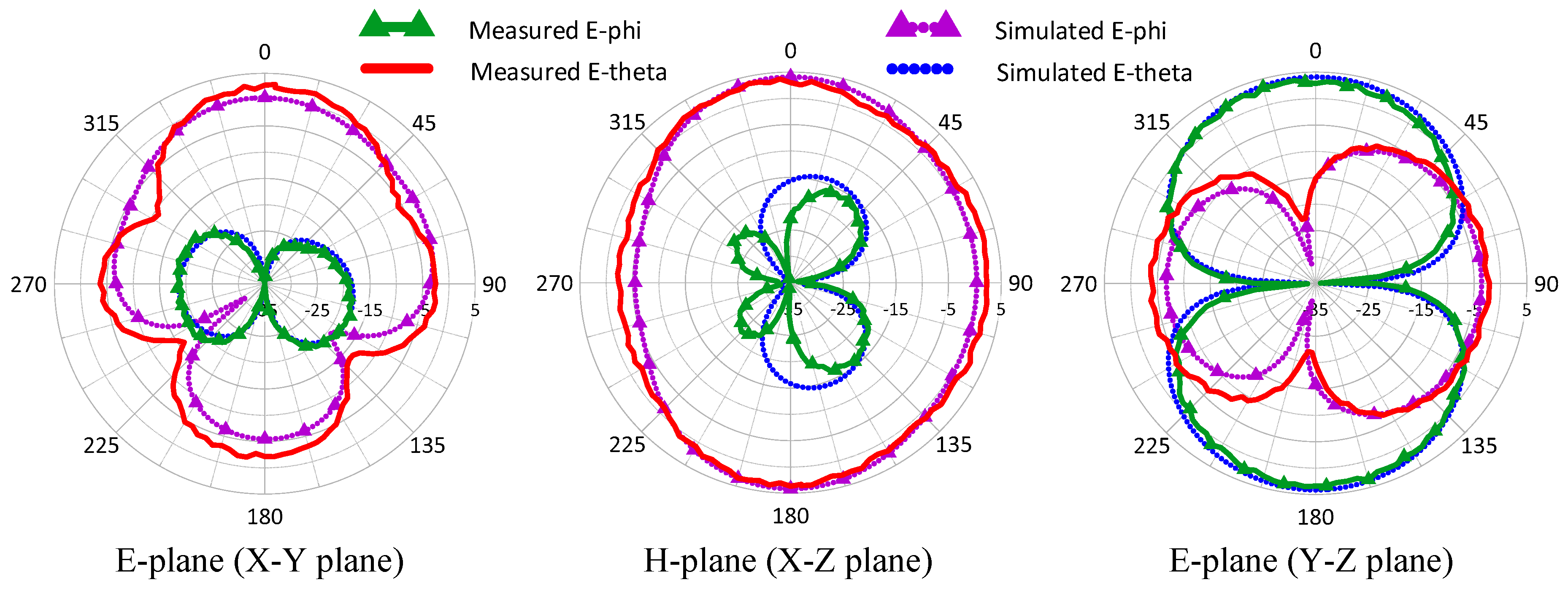
3. Measurement and Simulation Results

Figure 5a,b displays the simulated current distribution when the CPW of the proposed antenna operated in the even and odd modes, respectively. When diode A was on and diode B was off, the even mode of the CPW was excited, which generated vertical polarization on the semiloop antenna. As shown in Figure 5a, a current null could be found in the center of the semiloop antenna. By contrast, when diode A was off and diode B was on, the CPW produced an odd mode and generated horizontal polarization on the semiloop antenna. In this case, two current nulls could be found on the short edge of the semiloop antenna, as depicted in Figure 5b. The parameters W and L determine the resonant frequencies of the vertical and horizontal polarized modes, respectively. Finally, the optimized values of W and vl were W = 42 mm and vl = 16.8 mm.
Figure 6 shows the fabricated prototype of the proposed antenna. As shown in the figure, Diode A was biased through the blue wire and the red wire, while Diode B was biased through the red wire and the yellow wire. The DC switch control voltage was obtained by a battery, which provided a large current of about 10 mA to ensure the AC resistance was low. The measured and simulated reflection coefficients of the proposed antenna are depicted in Figure 7. The red line represents the reflection coefficient when the antenna operated in the even mode (vertical polarization mode), whereas the blue line represents the simulation reflection coefficient when the antenna operated in the odd mode (horizontal polarization mode). The resonant frequencies of the two polarization modes were both approximately 2.45 GHz. The achieved −10 dB impedance bandwidths covering the two operation modes were 4.92% (121 MHz) for the vertical and horizontal polarized modes.
The fabricated prototype was also tested in an anechoic chamber. Figure 8 and Figure 9 present the measured and simulated radiation patterns when the antenna operates in vertical polarization mode and horizontal polarization mode, respectively. The measured antenna gain at +Z direction was approximately 2.62 dBi for vertical polarization, while it was approximately 3.37 dBi for horizontal polarization. The simulated radiation efficiency for vertical polarization and horizontal polarization were 84.9% and 78.2%, respectively, where the parasitic effects of the PIN diodes shown in Figure 4 was taken into account. The measured and simulated results were in good agreement, the experimental verification of the proposed design shown that good polarization purity was obtained. Table 3 gives a comparison between the proposed antenna and other polarization reconfigurable antennas. From this table, it can be seen that the proposed antenna provided both polarization and pattern diversities in a smaller size with a switching circuit included, and used less diodes. The reduction in antenna gain might be attributed to the small resonator size due to electromagnetic physics.

4. Conclusions

This paper proposed a novel electrically reconfigurable semiloop antenna. It utilized a novel planar ACPS circular ring to change the modes of the CPW used to feed the semiloop antenna. The novel semiloop structure generated two orthogonal linear polarizations where the resonant frequencies of the two modes could be adjusted individually. In addition, this antenna element occupied a small footprint as compared to the popularly used patch, crossed-dipole, or crossed-slot design, over 40% dimension was saved. The proposed antenna required only one metal layer of a PCB including the switching circuit. The center frequency of the dual-polarization antenna was determined to be 2.45 GHz, and very low cross polarization was obtained.
This design provided switchable linear polarization in the +z/−z direction. It also could be used as a pattern diversity antenna because the achieved radiation patterns of the two modes were complementary. For the application of wireless local area network, if the antenna operated in the vertical polarization mode, the antenna provided the broadest coverage areas horizontally on the same floor. However, if the coverage needs to be increased to accommodate more users on the floors above and below, this antenna can be switched to horizontal polarization mode to provide greater vertical coverage.
The proposed design is planar, single layered, and easily be fabricated. Compared with polarization switchable antennas found in the literature, the proposed design is more suitable for integration with radio-frequency circuits and thin film printed circuit board.

Author Contributions

Conceptualization, Y.-J.C.; methodology, Y.-J.C.; software, C.-F.S.; validation, Y.-J.C. and C.-L.L.; formal analysis, C.-F.S.; investigation, Y.-J.C.; resources, C.-L.L.; data curation, C.-F.S.; writing—original draft preparation, Y.-J.C.; writing—review and editing, Y.-J.C.; visualization, Y.-J.C. and C.-F.S.; supervision, Y.-J.C. and C.-L.L.; project administration, Y.-J.C. and C.-L.L.; funding acquisition, Y.-J.C. All authors have read and agreed to the published version of the manuscript.

Funding

This research was funded by Ministry of Science and Technology, Taiwan, grant number MOST 106-2221-E-032-013-.

Conflicts of Interest

The authors declare no conflict of interest.

References

  1. Piazza, D.; Kirsch, N.J.; Forenza, A.; Heath, R.W.; Dandekar, K.R. Design and Evaluation of a Reconfigurable Antenna Array for MIMO Systems. IEEE Trans. Antennas Propag. 2008, 56, 869–881. [Google Scholar] [CrossRef]
  2. Raj, J.S.K.; Bonney, J.; Herrero, P.; Schoebel, J. A Reconfigurable Antenna for MIMO Application. In Proceedings of the Loughborough Antennas & Propagation Conference, Loughborough, UK, 16–17 November 2009; pp. 269–272. [Google Scholar]
  3. Pan, H.K.; Huff, G.; Roach, T.; Palaskas, Y.; Pellerano, S.; Seddighrad, P.; Nair, V.K.; Choudhury, D.; Bangerter, B.; Bernhard, J.T. Increasing channel capacity on MIMO system employing adaptive pattern/polarization reconfigurable antenna. In Proceedings of the 2007 IEEE Antennas and Propagation Society International Symposium, Honolulu, HI, USA, 9–15 June 2007; pp. 481–484. [Google Scholar]
  4. Boerman, J.D.; Bernhard, J.T. Performance Study of Pattern Reconfigurable Antennas in MIMO Communication Systems. IEEE Trans. Antennas Propag. 2008, 56, 231–236. [Google Scholar] [CrossRef]
  5. Iqbal, A.; Smida, A.; Mallat, N.; Ghayoula, R.; Elfergani, I.; Rodriguez, J.; Kim, S. Frequency and Pattern Reconfigurable Antenna for Emerging Wireless Communication Systems. Electronics 2019, 8, 407. [Google Scholar] [CrossRef] [Green Version]
  6. Trinh, L.H.; Le, T.N.; Staraj, R.; Ferrero, F.; Lizzi, L. A Pattern-Reconfigurable Slot Antenna for IoT Network Concentrators. Electronics 2017, 6, 105. [Google Scholar] [CrossRef] [Green Version]
  7. Dong, L.; Choo, H.; Heath, R.W.; Ling, H. Simulation of MIMO channel capacity with antenna polarization diversity. IEEE Trans. Wirel. Commun. 2005, 4, 1869–1873. [Google Scholar] [CrossRef]
  8. Al-Yasir, Y.I.A.; Abdullah, A.S.; Parchin, N.O.; Abd-Alhameed, R.A.; Noras, J.M. A New Polarization-Reconfigurable Antenna for 5G Applications. Electronics 2018, 7, 293. [Google Scholar] [CrossRef] [Green Version]
  9. DS, C.; Karthikeyan, S.S. A Novel Broadband Dual Circularly Polarized Microstrip-Fed Monopole Antenna. IEEE Trans. Antennas Propag. 2017, 65, 1410–1415. [Google Scholar]
  10. Li, W.; Leung, K.W.; Yang, N. Omnidirectional Dielectric Resonator Antenna with a Planar Feed for Circular Polarization Diversity Design. IEEE Trans. Antennas Propag. 2018, 66, 1189–1197. [Google Scholar] [CrossRef]
  11. Lin, W.; Wong, H. Wideband Circular-Polarization Reconfigurable Antenna with L-Shaped Feeding Probes. IEEE Antennas Wirel. Propag. Lett. 2017, 16, 2114–2117. [Google Scholar] [CrossRef]
  12. Zhang, L.; Gao, S.; Luo, Q.; Young, P.R.; Li, Q. Wideband Loop Antenna with Electronically Switchable Circular Polarization. IEEE Antennas Wirel. Propag. Lett. 2017, 16, 242–245. [Google Scholar] [CrossRef] [Green Version]
  13. Ge, L.; Yang, X.; Zhang, D.; Li, M.; Wong, H. Polarization-Reconfigurable Magnetoelectric Dipole Antenna for 5G Wi-Fi. IEEE Antennas Wirel. Propag. Lett. 2017, 16, 1504–1507. [Google Scholar] [CrossRef]
  14. Shi, Y.; Cai, Y.; Zhang, X.-F.; Kang, K. A Simple Tri-Polarization Reconfigurable Magneto-Electric Dipole Antenna. IEEE Antennas Wirel. Propag. Lett. 2018, 17, 291–294. [Google Scholar] [CrossRef]
  15. Wang, K.X.; Wong, H. A Reconfigurable CP/LP Antenna with Cross-Probe Feed. IEEE Antennas Wirel. Propag. Lett. 2017, 16, 669–672. [Google Scholar] [CrossRef]
  16. Hao, Z.-C.; Fan, K.-K.; Wang, H. A Planar Polarization-Reconfigurable Antenna. IEEE Trans. Antennas Propag. 2017, 65, 1624–1632. [Google Scholar] [CrossRef]
  17. Hu, J.; Hao, Z.-C.; Miao, Z.-W. Design and Implementation of a Planar Polarization-Reconfigurable Antenna. IEEE Antennas Wirel. Propag. Lett. 2017, 16, 1557–1560. [Google Scholar] [CrossRef]
  18. Row, J.-S.; Wei, Y.-H. Wideband Reconfigurable Crossed-Dipole Antenna with Quad-Polarization Diversity. IEEE Trans. Antennas Propag. 2018, 66, 2090–2094. [Google Scholar] [CrossRef]
  19. Zhong, L.; Hong, J.-S.; Zhou, H.-C. A Dual-Fed Aperture-Coupled Microstrip Antenna with Polarization Diversity. IEEE Trans. Antennas Propag. 2016, 64, 4524–4529. [Google Scholar] [CrossRef]
  20. Wu, F.; Luk, K.M. Single-Port Reconfigurable Magneto-Electric Dipole Antenna with Quad-Polarization Diversity. IEEE Trans. Antennas Propag. 2017, 65, 2289–2296. [Google Scholar] [CrossRef]
  21. Tang, M.-C.; Wu, Z.; Shi, T.; Ziolkowski, R.W. Electrically Small, Low-Profile, Planar, Huygens Dipole Antenna with Quad-Polarization Diversity. IEEE Trans. Antennas Propag. 2018, 66, 6772–6780. [Google Scholar] [CrossRef]
  22. Ge, L.; Li, Y.; Wang, J.; Sim, C.-Y.-D. A Low-Profile Reconfigurable Cavity-Backed Slot Antenna with Frequency, Polarization, and Radiation Pattern Agility. IEEE Trans. Antennas Propag. 2017, 65, 2182–2189. [Google Scholar] [CrossRef]
  23. Wu, F.; Luk, K.-M. A Reconfigurable Magneto-Electric Dipole Antenna Using Bent Cross-Dipole Feed for Polarization Diversity. IEEE Antennas Wirel. Propag. Lett. 2017, 16, 412–415. [Google Scholar] [CrossRef]
  24. Tran, H.H.; Nguyen-Trong, N.; Le, T.T.; Abbosh, A.M.; Park, H.C. Low-Profile Wideband High-Gain Reconfigurable Antenna with Quad-Polarization Diversity. IEEE Trans. Antennas Propag. 2018, 66, 3741–3746. [Google Scholar] [CrossRef]
  25. Mak, K.M.; Lai, H.W.; Luk, K.M.; Ho, K.L. Polarization Reconfigurable Circular Patch Antenna with a C-Shaped. IEEE Trans. Antennas Propag. 2017, 65, 1388–1392. [Google Scholar] [CrossRef]
  26. Chen, S.-L.; Wei, F.; Qin, P.-Y.; Guo, Y.J.; Chen, X. A Multi-linear Polarization Reconfigurable Unidirectional Patch Antenna. IEEE Trans. Antennas Propag. 2017, 65, 4299–4304. [Google Scholar] [CrossRef]
  27. Row, J.-S.; Huang, Y.-J. Reconfigurable Antenna with Switchable Broadside and Conical Beams and Switchable Linear Polarized Patterns. IEEE Trans. Antennas Propag. 2018, 66, 3752–3756. [Google Scholar] [CrossRef]
  28. Chang, L.-H.; Lai, W.-C.; Cheng, J.-C.; Hsue, C.-W. A Symmetrical Reconfigurable Multipolarization Circular Patch Antenna. IEEE Antennas Wirel. Propag. Lett. 2014, 13, 87–90. [Google Scholar] [CrossRef]
  29. Nguyen-Trong, N.; Piotrowski, A.; Hall, L.; Fumeaux, C. A Frequency- and Polarization-Reconfigurable Circular Cavity Antenna. IEEE Antennas Wirel. Propag. Lett. 2017, 16, 999–1002. [Google Scholar] [CrossRef]
  30. Li, Y.; Zhang, Z.; Chen, W.; Feng, Z.; Iskander, M.F. A Dual-Polarization Slot Antenna Using a Compact CPW Feeding Structure. IEEE Antennas Wirel. Propag. Lett. 2010, 9, 191–194. [Google Scholar] [CrossRef]
  31. Qin, X.; Li, Y. Compact Dual-Polarized Cross-Slot Antenna with Colocated Feeding. IEEE Trans. Antennas Propag. 2019, 67, 7139–7143. [Google Scholar] [CrossRef]
  32. BAR64-02V. Available online: https://www.infineon.com/dgdl/Infineon-BAR64-02V-DS-v01_01-EN.pdf?fileId=5546d462689a790c01690f0247ae38fc (accessed on 20 February 2020).
Figure 1. Geometry of the proposed antenna: (a) antenna structure; (b) coplanar waveguide (CPW) to asymmetric coplanar strip line (ACPS) transition; and (c) simulated surface current distribution of the transmission line structure.
Electronics 09 00708 g001
Figure 2. Reflection and transmission coefficient for the CPW to ACPS transition. Due to the symmetry, S31 is not shown.
Electronics 09 00708 g002
Figure 3. ACPS switching ring circuit: (a) position and polarity of the diodes; (b) even mode current flow; and (c) odd mode current flow.
Electronics 09 00708 g003
Figure 4. Equivalent circuit models of the diode when it is in the (a) off-state and (b) on-state.
Electronics 09 00708 g004
Figure 5. Simulated surface current distribution: (a) vertical mode and (b) horizontal mode.
Electronics 09 00708 g005
Figure 6. The fabricated prototype.
Electronics 09 00708 g006
Figure 7. Measured and simulated reflection coefficient.
Electronics 09 00708 g007
Figure 8. Measured and simulated vertical polarization mode radiation patterns at 2.45 GHz.
Electronics 09 00708 g008
Figure 9. Measured and simulated horizontal polarization mode radiation patterns at 2.45 GHz.
Electronics 09 00708 g009
Table 1. Optimized antenna dimensions.
Parameterabcder
Value3 mm0.3 mm10.64 mm4.8 mm10.64 mm11.2 mm
Parameterlwφvlvwhw
Value62.1 mm42 mm52°16.8 mm1.5 mm5 mm
Table 2. Switching states of the diodes and the generated polarization modes.
Pad APad BPad CDiode ADiode BPol.
Even modeHighLowLowONOFFV
Odd modeLowHighLowOFFONH
Table 3. Performance comparison with reported dual linearly polarized reconfigurable antennas.
Ref.Size (λ03)StructurePattern
Diversity
No. of DiodesSW CKT
Integrated
Substrate CostB.W. (%)Gain
[23]0.74 × 0.74 × 0.193Dno4yeshigh23.28
[25]1.63 × 1.63 × 0.093Dno2nohigh207.8
[30]0.82 × 0.65 × 0.008 2DΔnononenolow27.9/35.45.21/3.85
[31]0.29 × 0.29 × 0.008 2DΔnononenolow62.41
This work0.5 × 0.34 × 0.006 2Dyes2yeslow12.86/4.912.62/3.37
Δ double sided PCB. ◎ single sided PCB.

