1. Introduction
The last few decades have witnessed a significant growing demand and quantity of mobile users [
1,
2]. The total volume of traffic on data networks and the number of active subscribers has increased at an exponential rate, especially in contemporary networks. In order to meet the requirements of these subscribers, a new advancement known as 5G of mobile communications has been introduced [
3,
4]. 5G offers larger mobile data volume per unit area of several orders of magnitude with a reduced latency of up to 5 times while improving the connectivity of devices by 100 times [
5]. Furthermore, the newly developed 5G standard is expected to confront a similar surge of subscriptions once rolled out. Nonetheless, 5G users would require adequate resources such as bandwidth and energy [
6] in order to cater to the demands of an ever growing data traffic. In 5G networks, cell sizes are expected to be tiny enough to enable the utilization of high frequency bands that provide coverage in a limited area. This feature would increase the number of handoffs and will pose new challenges.
A Cyber Physical System (CPS) is a system of collaborating computational components that supervise physical entities. The CPS applications mostly include narrowband data traffic services such as IoT, smart cities, industrial internet, smart grids and smart anything including cars, buildings, homes, manufacturing, hospitals, and appliances, etc., [
7]. The advent of 5G technologies has enabled an exponential increase in the use of CPS. The information processing through these devices would require scheduling of resources according to their significance, which would ultimately help in reducing the network congestion and timely delivery of useful information.
Observations show that cost-effectiveness is crucial for network operators [
1]. An approach with a reduced cost can be achieved by utilizing various mechanisms for efficient utilization of spectrum. Network operators can help in achieving better spectral efficiency by allocating radio resources effectively. Radio resource scheduling in uplink for 5G networks is the primary focus of this article. Scheduling can be defined as the use of scarce and precious radio resources in an efficient manner in order to draw maximum throughput, while maintaining the fairness under consideration without compromising the provision of service guarantee. An inefficient scheduling of resources results in congestion of the network and hence an increased end-to-end delay and poor data rate performance. Furthermore, the air interface could be wasted if the required level of throughput and services are not achieved. Therefore, attaining an acceptable degree of quality-of-service (QoS) satisfaction becomes a challenge in radio resource management. In addition to that, the mobility of nodes and devices further complicates the problem.
Radio resource management techniques have been studied by various researchers over the years. Some radio resource management algorithms pertain to heavy traffic [
1], while others target low traffic conditions [
2]. Some radio resource management techniques are so complex that extremely expensive network nodes would be required to be deployed at both the user-end as well as the network side in order to ensure effective and efficient communication. The resource allocation mechanisms must consider the trade-off between complexity and performance while designing a network. The main objective of this work is to present a resource scheduling scheme that can enhance the throughput without sacrificing the QoS requirements, such as meeting end-to-end delay requirements. Quality class identifier (QCI) is associated with every radio bearer based on some parameters including packet loss, bearer delay and bearer priority.
The link adaption (LA) in mobile networks aims to optimize the transmission rate in mobile networks. The LA feature controls the transmission rate by keeping the channel conditions in consideration. Channel quality indicator (CQI) is a mechanism that is used to provide the information of downlink channel conditions of user equipment (UE) to the 5G base station, called the gNodeB. Similarly, sounding reference signals (SRS) provide uplink channel condition information to the gNodeB. Using this information, the gNodeB can perform LA-based decisions such as determination of modulation and coding scheme (MCS), transmit power, and transmission bandwidth.
The design of a scheduling algorithm is usually not standardized in advanced mobile networks. Rather the network designers/service providers are given the choice of tailoring their own scheduling schemes. Scheduling is achieved at the medium access control (MAC) layer of the protocol stack of gNodeB at the radio access part of the network. For this reason, the scheduler is often referred to as the MAC scheduler in the literature. In case data is available for transmission in the uplink buffers of UEs or CPS, the buffer status report (BSR) mechanism notifies the presence of data to the serving gNodeB and radio resources are requested for transmission of data in the uplink direction. The functions of BSR also include sending information about traffic type, e.g., video or voice traffic to the gNodeB. The process of scheduling in mobile networks is dynamic for both the downlink and uplink directions. Such dynamic nature of resource allocation along with LA can improve spectral efficiency considerably. The scheduling decisions are usually performed in a discrete time manner. The time period during successive scheduling decision events is known as transmission time interval (TTI). In each TTI, the scheduler assigns resources to an updated list of users. Scheduling is carried out after dissemination of information about resource allocation to each user in the serving gNodeB. Schedulers use some metric value based on the parameters such as channel conditions and traffic type in order to determine the priority of a user. In general, high priority users are scheduled earlier than low priority users.
In this paper, an uplink radio resource allocation scheme is proposed with focus on CPS in 5G networks. The proposed scheme is designed to perform allocation of radio resources by giving importance factors such as channel condition, QoS guarantee and fairness. In
Section 2, 5G air interface schemes are reviewed.
Section 3 gives an overview of existing scheduling schemes in literature and data traffic types in mobile networks.
Section 4 explains working principles of popular scheduling mechanisms as well as the description of how the proposed scheme works. In
Section 5, a simulation model design is presented followed by simulation results and comparison of famous scheduling schemes versus the proposed scheme. Finally,
Section 6 concludes the paper with a mention of future intentions of the authors in this research.
2. 5G Schemes for Air Interface
5G offers terrestrial as well as satellite air interface schemes [
8]. In terrestrial air interface mechanisms, the well-known 4G air interface scheme of orthogonal frequency division multiplexing (OFDM) is considered inefficient for handling narrowband data traffic [
9] as in the case of CPS. Therefore, new air interface schemes have been developed for 5G systems and known as new radio multiple access (NR-MA) schemes. These schemes are broadly categorized as codebook-based, sequence-based and interleaver/scrambler-based schemes [
10]. Filtered OFDM (F-OFDM) overcomes OFDM issues of high side lobes, interference and higher power consumption [
11]. F-OFDM also offers resource allocation flexibility as bandwidth can be parted into variable sized subbands for different applications by applying dynamic numerology, as compared to the persistent numerology of OFDM for the whole spectrum [
12]. The time-frequency resource sharing feature of code division multiple access (CDMA) and the division of bandwidth into subbands for multiple users feature of orthogonal frequency division multiple access (OFMDA) are combined to achieve sparse code multiple access (SCMA) mechanism for air interface in 5G [
13]. The idea of resource sharing via code domain was pitched quite some time ago in [
14].
3. Medium Access Scheduling in Literature and Data Traffic
Accommodating growing demands of mobile users and keeping costs under control is a daunting task. The reason is that the mobile service providers are now looking for integration of mobile and wireless local area networking technologies [
3]. Keeping in view the users’ needs and meeting bandwidth requirements, technologies such as virtualization and cloud are suggested for mobile networks [
4]. The world today is a cyber physical space [
15] where social problems are solvable through data driven decision making systems. In today’s global telecommunications, not only information but different types of communication devices and sensors are being linked to networks by leading information and communication technology (ICT) experts. To cope with such information and use bandwidth efficiently, some advanced methods of radio resources allocation are discussed in [
16]. A number of scheduling schemes exist for contemporary and future mobile networks [
5,
17,
18]. The authors of [
19] present and evaluate scheduling schemes for a FlexRay network—an advanced standard for automotive communications. In present day mobile networks, the research work is mostly focused on downlink scheduling [
20,
21,
22]. A very insubstantial volume of literature addresses uplink scheduling mechanisms, where uplink constraints are taken into consideration [
23,
24,
25]. Even in uplink scheduling, a large share of research work targets LTE and LTE-A. The uplink scheduling in 5G networks is also discussed in works such as [
26,
27] but some aspect such as QoS, IoT and CPS data traffic issues are not covered. Even though physical layer aspects are covered in several research papers as discussed above, the MAC layer functionalities with cross layer development approaches are rarely discoursed in the available literature for 5G specific MAC features. This work attempts to devise a scheduling scheme that is capable of modelling the uplink idiosyncrasies and enables an efficient allocation of resources with service awareness.
The data traffic can mainly be divided into two types of bearers, i.e., guaranteed bit rate (GBR) and non-guaranteed bit rate (NGBR). In general, network resources are persistently available for GBR bearers because of their greater importance and priority. The data traffic of time critical cyber physical systems (TCCPS) is considered as GBR. non-Time critical cyber physical systems (NTCCPS)-based traffic is mapped as NGBR traffic. TCCPS traffic normally has lower bandwidth requirements but strict latency constraints. To ensure these provisions, bearers are prioritized by giving higher metric values to important users. The metric values rely on parameters such as average throughput of a particular CPS or user
at time
. Such a throughput is denoted here by
and determined with the help of an exponential moving average (EMA) time window of duration equal to one TTI. The updated value of average throughput after each TTI is determined as in Equation (1):
where
is the TTI duration and
is the data rate in bits that user
has recently achieved in the previous TTI of scheduling decision.
4. Uplink Scheduling Description
The scheduling schemes used in uplink and downlink are independent of each other, just like the channel conditions of uplink and downlink signals. Therefore, several dissimilarities exist between uplink and downlink radio resource scheduling mechanisms. For instance, power constraints do not prevail in downlink due to the availability of ample power at the base station. In uplink, power consumption is a critical aspect because devices used on the user side are battery operated and power saving is imperative.
In scheduling schemes, some of the important performance evaluation parameters are throughput, latency, fairness, and power control. The power required to transmit a single resource block is a function of frequency and called power spectral density (PSD). Power control mechanisms in uplink are required to maintain some required level of signal-to-interference-and-noise-ratio (SINR) for signals arriving at the gNodeB, so that dynamic range at the gNodeB receiver can be minimized. Power control also mitigates intercell interference by reducing transmit power for cell-edge users. A CPS is expected to get a lower number of resource block(s) in a particular TTI if located at a point where unsatisfactory channel conditions are experienced. The scheduler is provided information about each resource block of every CPS. Power headroom report is generated at the user side and contains information about user PSD. This information is conveyed to the gNodeB for facilitating scheduling decisions. Furthermore, a significant amount of bandwidth can be conserved for other CPS by allocating radio resources in an efficient manner. The additional uplink constraints make the uplink scheduling even more complicated as compared to the downlink.
This paper presents a radio resource scheduling scheme for uplink data that is the Service Aware (SA) scheduler deployed in the MAC layer of the gNodeB. The SA scheduler is designed to serve users and CPS by providing some level of priority based on channel conditions, QoS and fairness. Furthermore, SA offers special care to cell-edge users, typically under bad channel conditions in order to provide adequate resources and avoid starvation. The SA scheduler also ensures QoS guarantees to users with data traffic of high priority requirements. The SA scheduler is divided into two distinct working units, i.e., time domain packet scheduler (TDPS) and frequency domain packet scheduler (FDPS). In the time domain, a list of CPS having higher time domain metric values are selected for resource block allocation in the next TTI. In the frequency domain, the resource blocks are assigned to the selected CPS according to frequency domain metric values.
4.1. Time Domain Packet Scheduling
The uplink data, i.e., the data in the transmission buffer of CPS, is reported to gNodeB using the BSR mechanism. This activity is used to initiate a radio resource request. The bearer status of a CPS is also reported through BSR, while channel conditions of the CPS are reported to base station through SRS. Such mechanism generates a list of active CPS which are having data ready for uplink transmission at the gNodeB and enables the availability of information about their channel conditions at the gNodeB. The active CPS list contains a list of users that are marked as ready for transmitting information. Subsequently, this initiates the resource requests for the marked users. Through power headroom report, the gNodeB is made aware of the PSD of CPS. All the CPS are then prioritized depending on TDPS metric values assigned to them for a specific TTI. CPS with the highest metric value are selected for resource block allocation in the FDPS. The performance of the SA scheduler is compared with three well known schedulers in this research. A brief account of such schedulers is presented here followed by the proposed SA scheduler specifications.
4.1.1. Time Domain Blind Equal Throughput
In the time domain blind equal throughput (TD-BET) scheduling algorithm, the objective is to serve all active nodes with uniform throughput distribution regardless of the channel conditions whether good or bad. This scheme boasts a very fair algorithm and users at the cell-edge also benefit accordingly. However, this impartiality is dispensed at the expense of poor throughput performance on the cell level. If
is the TDPS metric value of user
at time
and
is the average throughput of user
over a time window of duration equal to TTI at time
found using equation (1), then the metric value
is determined as in Equation (2):
The TD-BET scheme disregards channel conditions and throughput achieving capacity of users, but ensures that fairness is delivered.
4.1.2. Time Domain Maximum Throughput
Time domain maximum throughput (TD-MT) attempts to enhance the user experience of nodes undergoing good channel conditions. So, users are prioritized according to their channel conditions. This approach results in achieving a higher cell throughput. However, the drawback is that users with poor channel status will have to suffer, especially the cell-edge users. The throughput maximization is achieved at the cost of fairness. Cell-edge users could even experience starvation under TD-MT. The metric value for TD-MT scheduler is established as in Equation (3):
where
is the data rate in bits that user
can achieve in the current TTI if the whole bandwidth is allocated for scheduling to user
. The determination of
is realized by finding the system level SINR of user
and using the Transport Block Size (TBS) tables of 3GPP to get the total number of bits that the whole system bandwidth can accomplish [
28].
4.1.3. Time Domain Proportional Fair
Time domain proportional fair (TD-PF) scheduling scheme provides a middle way out to the scientists working on radio resource management schemes in such a way that the scheme strives to enhance throughput. However, a certain level of fairness is also delivered to the users inside a cell. The algorithm is used to optimize the fairness and throughput trade-off. The TD-PF metric value is generated as in (4):
Here, instantaneously attainable throughput and EMA throughput both play a key role in determining the TDPS metric value.
4.1.4. Time Domain Service Aware
The scheme proposed for the time domain scheduling of CPS is an enhanced form of the TD-PF where fairness as well as throughput concerns are addressed. Furthermore, the QoS and power control obligations are taken into consideration. Traffic types with varying delay requirements are given priority based on the bearer type. The TD-SA metric value is derived as in Equation (5):
where
is the data rate in bits that the user
can achieve in the current TTI if the number of maximum obtainable resource blocks is
, while
is the service-based weightage of user
for bearer
. The maximum obtainable resource blocks are determined with the help of power control mechanism. The maximum user transmit power is fixed to 23 dBm as per 3GPP specifications. In case of adverse channel conditions, the power control mechanism would be required to increase the PSD of the transmit signal. So, the signal can arrive at the base station with an acceptable SINR. However, the increase in PSD should not breach the maximum user transmit power.
In case the PSD increase is inevitable for a user, the total number of resource blocks allocated to that user is restricted. This number of resource block allowed under power control is represented by
. Thus,
is a function of
as well as
. The service weight
of user
for bearer
depends upon bearer type, i.e., GBR or NGBR. All the weights are accumulated to determine the collective service weight of the user. In order to ensure high priority for GBR users, the
value for GBR bearer
is determined as in Equation (6):
where
is the buffer waiting time for the first-in-queue packet ready for transmission in the user buffer,
is the delay budget of the service class of bearer
, while
is a bearer specific weighting factor used for delay sensitive traffic with higher values, depending on the traffic environment, while a value of 1 is imparted for traffic with a lower delay sensitivity.
4.2. Frequency Domain Packet Scheduling
In the FDPS part of radio resource management scheme, the primary goal is providing frequency resources to selected high-priority users. The selection of users is based on the TDPS metric values of users and the allocation of frequency resources is carried out in each TTI. The resource blocks are allocated to users on the basis of FDPS metric values, which are assigned to each resource block of each selected user. The process is repeated iteratively as long as resource blocks are available in the system bandwidth. In the frequency domain, the metric values may rely on parameters such as the central tendency of channel conditions. For central tendency, the mean SINR value of user
is derived as in Equation (7):
where
is the EMA SINR of user
at time
and
is the SINR achieved during the previous TTI. The mapping of resource blocks to users is performed with the help of FDPS schemes. Some of these schemes are discussed here.
4.2.1. Frequency Domain Round Robin
Frequency domain round robin (FD-RR), a frequency domain scheduling strategy, is designed to allocate resources to all selected resources in a round robin manner until all the resource blocks have been allocated. The allocation process ideally starts with the user that has the highest TDPS metric value.
4.2.2. Frequency Domain Maximum Throughput
The frequency domain maximum throughput (FD-MT) algorithm straightforwardly checks the SINR values of each user for all resource blocks and assigns the resource block with the highest metric value to the most prioritized user in an iterative manner as long as the availability of resource blocks in the system is established. The iterations recur until the system runs out of resource blocks. The frequency domain metric value for user
at resource block
is derived as in Equation (8):
where
represents the resource block index having values from 0 to
if there are
resource blocks in the system,
is SINR for user
over resource block
at time
. The main objective of FD-MT is to allocate resources to those users that are capable of facilitating the cell throughput maximization.
4.2.3. Frequency Domain Proportional Fair
The frequency domain proportional fair (FD-PF) scheduling scheme is designed to improve throughput performance along with some level of fairness. Therefore, while considering the SINR values of resource blocks for each user, the EMA throughput of the users is also considered as shown in Equation (9).
4.2.4. Frequency Domain Service Aware
The proposed scheme takes the FD-PF scheme to another level, where resource blocks are allocated not just in a proportionally fair manner, but also with a greater importance pronounced for delay sensitive users. The FDPS metric value under FD-SA for resource block
of user
at time t can be expressed as in equation (10):
where
is the service weight of user
for bearer
at time
. The service weights of all bearers are accumulated in Equation (10) to determine the total service weightage of user
. However, the service weight is applied only if a particular bearer is experiencing delay beyond a specified threshold. Therefore, the value of
is expressed as in Equation (11):
Since the proposed scheduling scheme gives significance to power control, the allocation of resource blocks is carried out in such a manner that the maximum allowed transmit power for a device is not exceeded.
5. Simulation System
OPNET modeler [
29] is used to simulate and analyze the proposed resource allocation scheduler in a comparative study. OPNET is widely used as one of the contemporary tools of research and development for simulation and analysis of mobile communication systems [
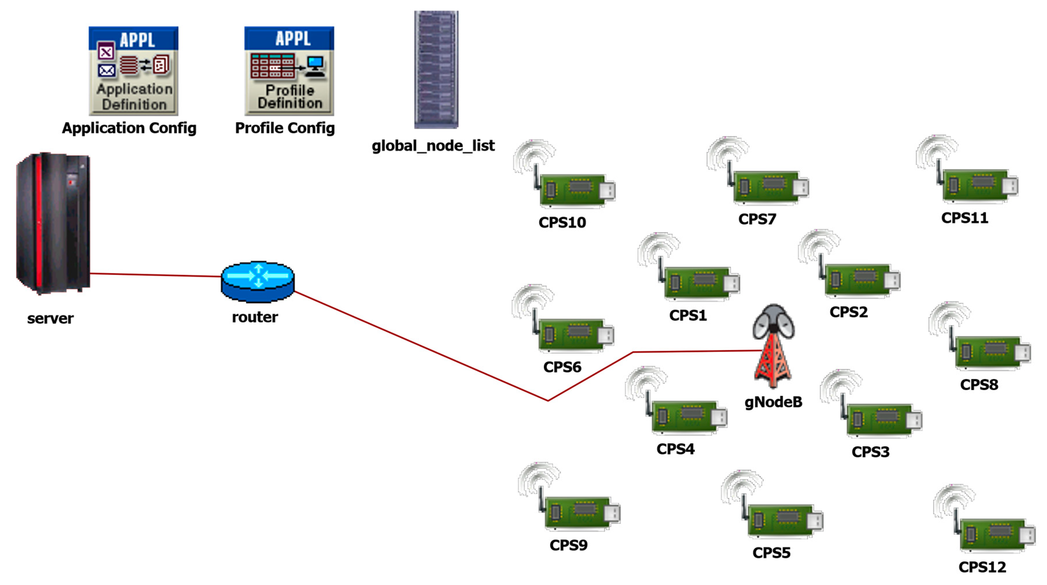
30]. In the simulation system developed, a single gNodeB is used to create a cellular environment as in
Figure 1. Several CPS are deployed in the system and are being served by the gNodeB. The gNodeB is connected to a server in the core network part through a router, where the role of the server is to act as a destination for uplink packets and origin for downlink packets.
The CPS are further divided into two types, i.e., CPS for delay critical information and delay insensitive information. The CPS devices are placed in three different zones in the cell, each zone characterizes the distance of CPS transmission systems from the gNodeB. Devices are considered to be in the “near” zone if the distance between CPS and gNodeB is 150 m. Devices are considered as “far” if the device is 250 m far from gNodeB. Finally, “cell-edge” devices are those having a distance of 350 m from gNodeB.
In
Figure 1, the devices labelled CPS1, CPS2, CPS3 and CPS4 are near users, while CPS5, CPS6, CPS7, and CPS8 are far users, and CPS9, CPS10, CPS11 and CPS12 are cell-edge users. In total, three TDPS scheduling mechanism are compared with SA, i.e., MT, BET and PF. In FDPS, the SA scheme is used for all the scheduling schemes. Uplink cell throughput and end-to-end delay are the parameters used to compare the schemes of the simulation scenarios performed in this work. Simulation parameters are illustrated in
Table 1, while simulation results are elaborated and explained in detail. It is important to mention that two types of data traffic are used in the simulation scenarios. The delay tolerant type of traffic is the video traffic while delay sensitive traffic is the voice traffic. Although the proposed SA scheme is based on a power control mechanism and facilitates power consumption reduction, but the power related analysis has not been performed in this paper.
5.1. Sensitivity Analysis
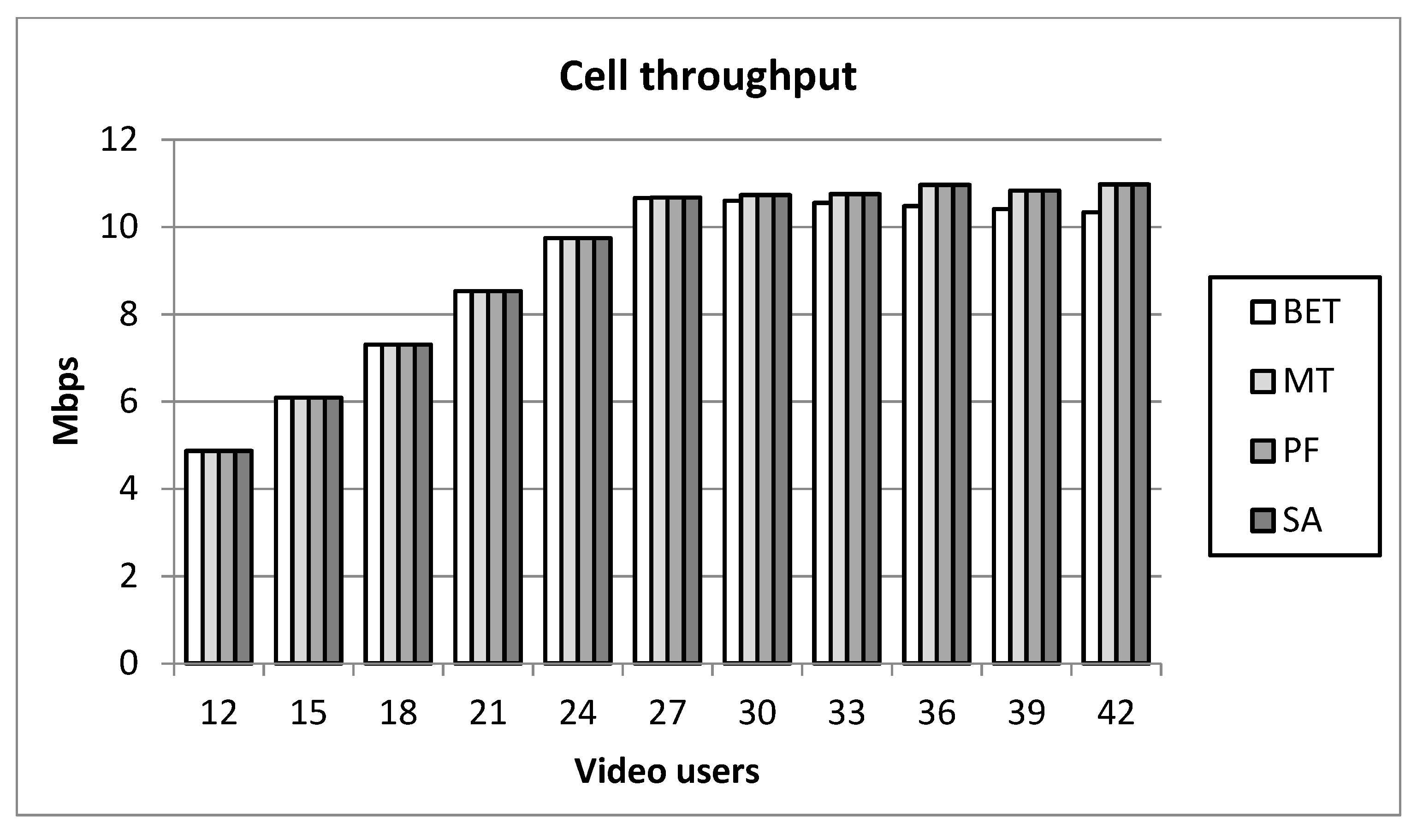
The purpose of sensitivity analysis is to find a traffic load point where the cell starts to behave as a loaded environment. Four schedulers, i.e., the well-known BET, MT, PF schedulers and the proposed SA scheduler are used in the sensitivity study. The uplink cell throughput of all the schedulers is compared and shown in
Figure 2 in such a way that the number of CPS devices transmitting video packets in various scenarios is represented through the set {12, 15, 18, 21, 24, 27, 30 33, 36, 39, 42}. The distribution of near, far and cell-edge users in all the scenarios is uniform. Each scheduler is simulated for a total of ten runs and the final result of a particular scenario is determined by taking average of all the relevant runs. After completion of ten runs for each of the scheduler, an increment of one near, one far and one cell-edge CPS devices is done in order to increase traffic in the cell step-by-step. The graphs in
Figure 2 show that all the schedulers behave similarly to a certain extent, a growing trend at low load and sustained trend at a higher load due to the congestion in the cell. The point at which the behavior of the scheduler changes from linearly increasing function to quasi-consistent function is determined in sensitivity analysis in order to find the threshold at which the cell becomes loaded but not yet congested. In this work, 27 video users are chosen to correspond to such a situation.
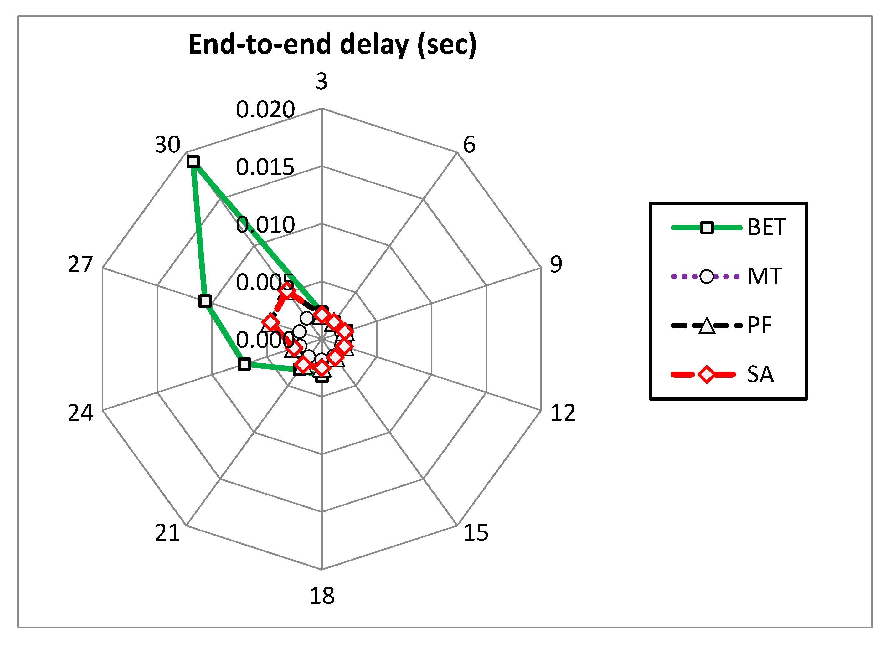
In order to understand the behavior of schedulers, the end-to-end delay from the devices to the server is observed for all the schedulers as shown in
Figure 2.
Figure 3,
Figure 4 and
Figure 5 depict the end-to-end delay performance results for near, far and cell-edge users, respectively. In these figures, graphs are illustrated with the help of spider web charts where the round axis represents the number of video users, while the trans-axis represents the end-to-end delay in seconds.
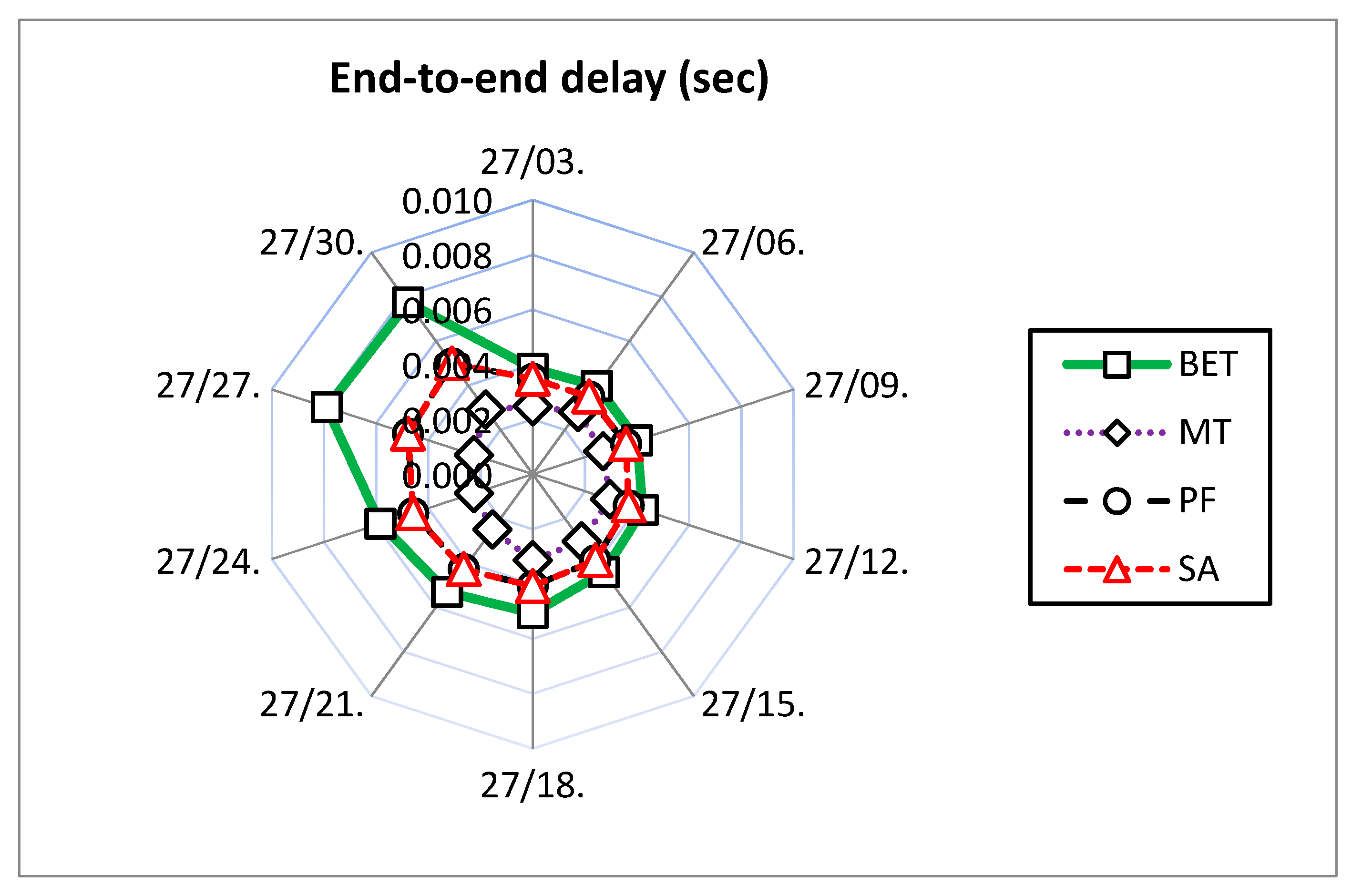
Results in
Figure 3 illustrate that the average packet end-to-end delay for MT scheduler is less than all other schedulers because MT scheduler gives all the resources to users with good channel conditions, i.e., near users. The end-to-end delay results for BET scheduler show large delays as compared to other schedulers. The reason is that BET blindly distributes equal resources to all users. The BET is an extremely fair scheduler, but the cost of fairness is poor throughput and inferior delay performances of near users when compared to other schedulers. The PF and SA schedulers behave in similar fashion since both offer fairness proportionally and there is only one type of traffic, thus the service weight factor of SA scheduler will not play any role.
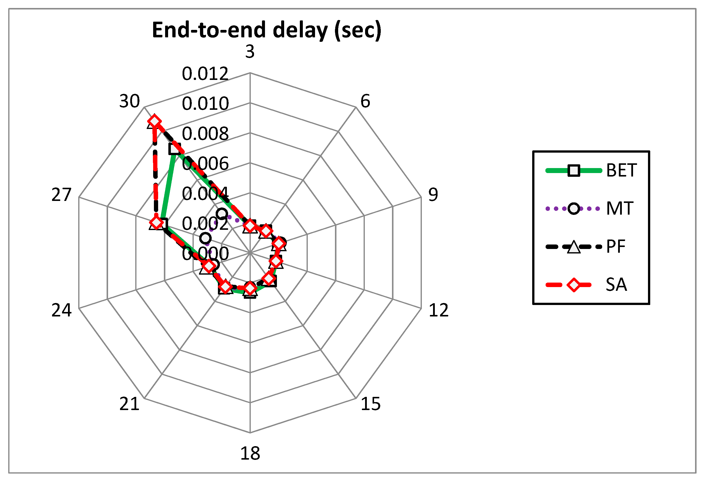
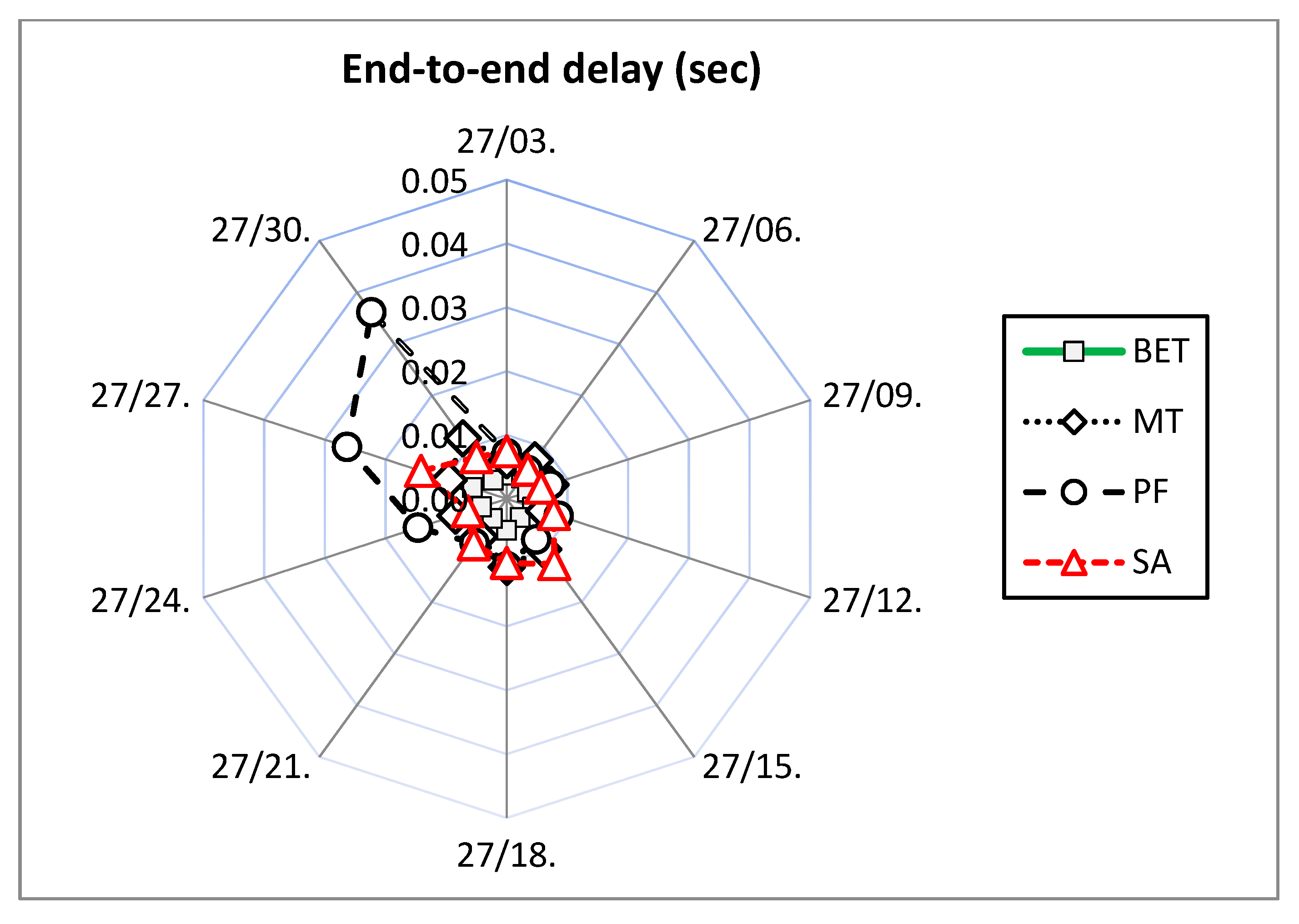
Figure 4 depicts average packet end-to-end delay results for far users in the cell. The channel conditions for far users are comparatively poorer than the near users. In this case, the MT scheduler still performs better than the BET scheduler. However, the performance of SA and PF schedulers is degraded now, especially when the number of users is increased beyond twenty-four. It may be noted that BET performance for far users is better than near users. The urge for providing equal throughput to all users in BET scheduling case results in performance degradation of near users.
The average packet end-to-end delay results in
Figure 5 for cell-edge users depict that MT scheduler now performs the worst among all schedulers because the cell-edge users are under adverse channel conditions. The BET scheduler’s performance is the best of all because BET equally distributes resources to every user without considering the channel conditions, thus cell-edge user for BET scheduler are beneficiaries at the expense of near users.
5.2. Performance Evaluation
The rest of the simulations show a comparison of the performance, i.e., throughput and delay of various schedulers. The traffic load for video users is consistently 27 devices, whereas the number of voice users is altered in order to create varying load and service scenarios. Hence, all the scenarios contain mixed traffic. In the spider web charts, the round axis represents the number of video/voice users and the trans-axis would either represent end-to-end delay in seconds, or throughput in Mbps.
5.2.1. Voice Results in Mixed Traffic Environment
Along with video users, voice users are also deployed into the simulation environment such that the number of voice users varies in subsequent scenarios as expressed in the set {3, 6, 9, 12, 15, 18, 21, 24, 27, 30}. Again, the numbers of near, far and cell-edge users are uniformly distributed.
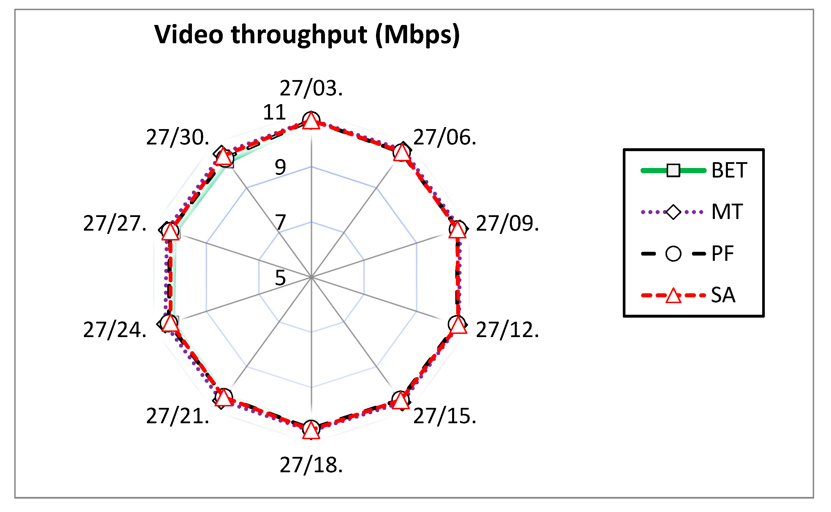
Figure 6 depicts the situation of voice throughput for all four schedulers in varying voice load scenarios.
The graphs in
Figure 6 show that all schedulers treat voice traffic in a similar manner in terms of throughput. Therefore, it is evident that one way or the other, the voice traffic achieves a higher priority from different schedulers, either due to the smaller packet size or service weight.
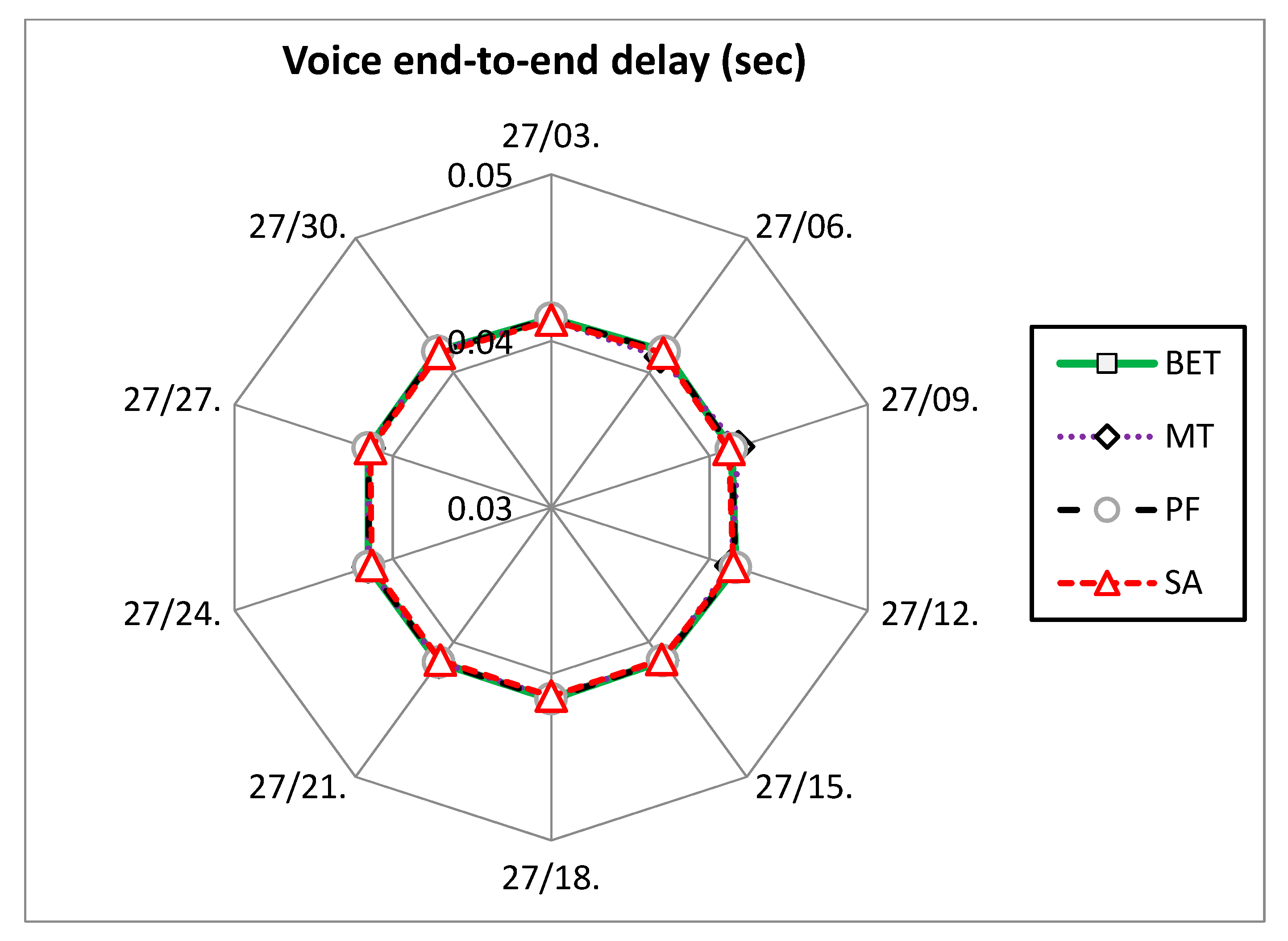
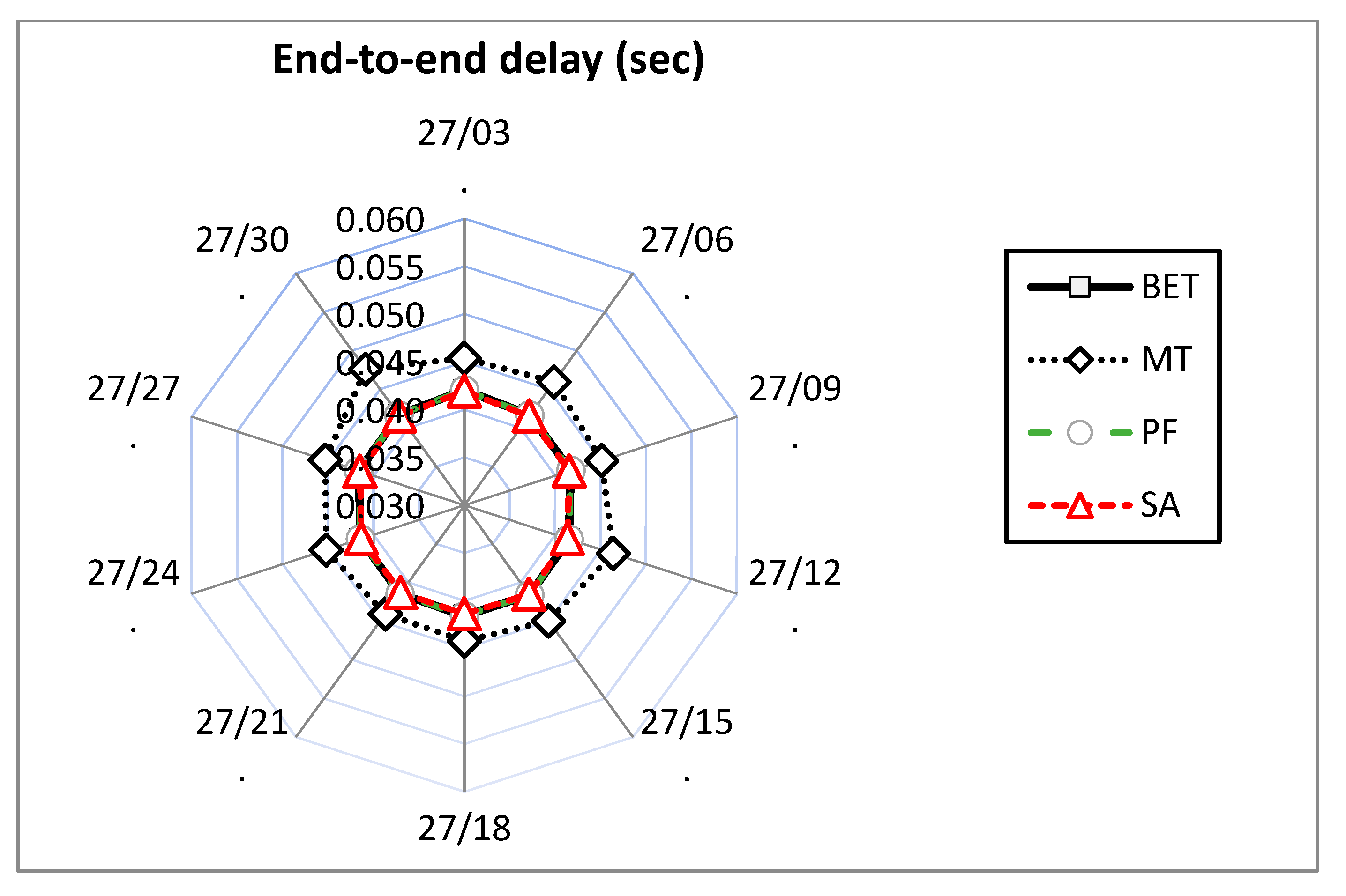
The delay critical traffic usually requires a lower amount of resources per user due to lower data rates. The delay performance of schedulers for such traffic reveals consistent treatment of voice data in varying traffic load scenarios as shown in
Figure 7,
Figure 8 and
Figure 9. The packet average end-to-end delay for near users is similar for every scheduler. The near user end-to-end delay results are also depicted in the
Figure 7. In
Figure 8, the graphs show a similar outlook as
Figure 7 with the exception of MT scheduler where the delays show a slight increase. This is natural, because MT scheduler performance would degrade if the distance between gNodeB and users increase. In
Figure 9, the end-to-end performance of cell-edge users show further increase in delays for MT scheduler.
5.2.2. Video Results in Mixed Traffic Environment
The video results are presented and analyzed. The video traffic performance would determine how a scheduler performs under multi bearer environment. Voice traffic got resources on priority basis, and the leftover resources are to be availed by video users.
A glance at
Figure 10 illustrates that in contrast to voice throughput, video throughput remains consistent in all scenarios, obviously due the fact that video users are a constant 27 in the cell. This result might seem to be an insignificant finding, but the schedulers’ behavior is discovered once the delay performance is appraised in the near, far and cell-edge zones.
Figure 11 depicts a representation of the average packet end-to-end delay performance of video users labelled as near users. As expected MT scheduler performs very well in case of near users, which reflects that users with good channel conditions are prioritized by MT scheduler. However, BET results for near users are not significantly better, especially when the number of voice users is increased and therefore the video users under BET scheme suffer. PF and SA schedulers’ performances are much better as compared to BET scheduler.
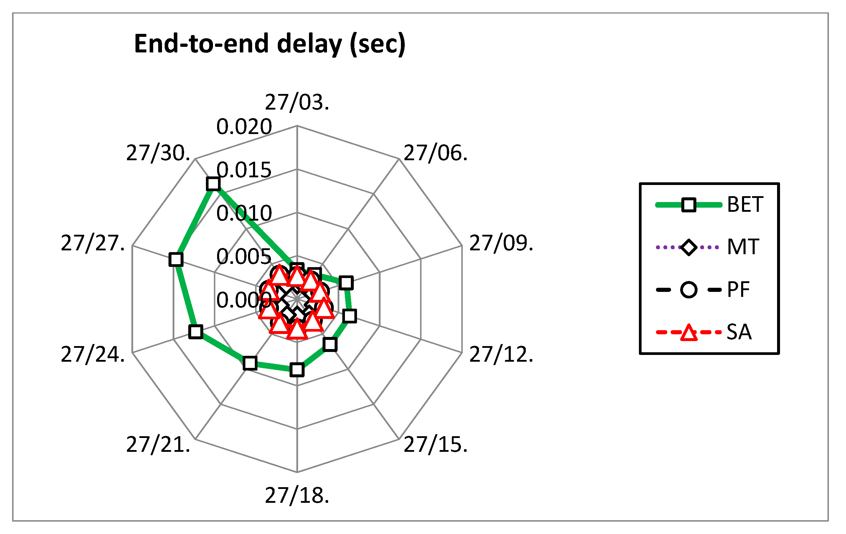
In
Figure 12, the performance of schedulers is evaluated for far users in terms of video packet average end-to-end delay. The performance of BET scheduler is improved now as compared to near users’ performance. In the case of MT scheduler, the performance is somewhat degraded as far users have relatively poor channel conditions due to the increase in the distance from gNodeB. The performance of SA and PF schedulers is better than the MT scheduler.
Figure 13 shows a few aspects of results for packet end-to-end delay performance of cell-edge users. The performance BET scheduler has improved because cell-edge users are enjoying resources at the expense of near users. The performance of the PF scheduler has deteriorated drastically, specifically in the scenarios when the number of voice users is higher. This is where the multi-bearer support feature of SA scheduler based on service weight comes into play. The PF scheduler in multi bearer traffic does not provide service awareness while the SA scheduler boasts QoS-based differentiation.
6. Conclusions
In this paper, the design of a medium access scheduling scheme, the SA scheduler, is proposed. The proposed design is implemented, evaluated and compared to other renowned schedulers in the literature for different types of traffic and varying environmental conditions. The other schedulers, i.e., MT, BET and PF have their pros and cons. Some of the situations favor one scheduler and some suit another scheduler. However, results in different load environments illustrate that the SA scheduler stands out as the only scheduler that can endure any type of traffic load or QoS burden. The MT scheduler generally outperforms others in ideal channel conditions. The BET scheduler provides better results for cell-edge users as compared to other schedulers mainly because it blindly distributes radio resources among users. The PF is an amalgam of both MT and BET schedulers as throughput maximization and fairness are both given weightage. However, PF scheduler is prone to fail when service distinction is required. In the case of multi bearer traffic, the PF scheduler may not be able to distinguish between delay sensitive and delay tolerant traffic. The performance of the SA scheme is not different from the PF scheme with signal bearer traffic. However, it has the ability to differentiate between important and less important users. In the future, we aim to simulate a carrier aggregation-based scheduling that can support up to five components carrier for further improvement. Furthermore, such a scheme would be analyzed with more than two bearers in a mixed traffic environment.
Author Contributions
Conceptualization, methodology, software, S.N.K.M.; formal analysis, writing—original draft, M.S.; investigation, project administration, S.A.; validation, writing—review & editing, A.H.; resources, supervision, M.T. All authors have read and agreed to the published version of the manuscript.
Funding
This research was funded by the Higher Education Commission of Pakistan.
Acknowledgments
The simulation environment was developed while S.N.K.M. was working at the University of Bremen, Germany for which we are thankful to University of Bremen, especially Yasir Mehmood.
Conflicts of Interest
The authors declare no conflict of interest.
References
- Hasan, Z.; Boostanimehr, H.; Bhargava, V.K. Green Cellular Networks: A Survey, Some Research Issues and Challenges. IEEE Commun. Surv. Tutor. 2011, 13, 524–540. [Google Scholar] [CrossRef]
- Dutta, U.K.; Razzaque, M.A.; Al-Wadud, M.A.; Islam, M.S.; Hossain, M.S.; Gupta, B.B. Self-Adaptive Scheduling of Base Transceiver Stations in Green 5G Networks. IEEE Access 2018, 6, 2169–3536. [Google Scholar] [CrossRef]
- Andrews, J.G.; Buzzi, S.; Choi, W.; Hanly, S.V.; Lozano, A.; Soong, A.C.K.; Zhang, J.C. What Will 5G Be? IEEE J. Sel. Areas Commun. 2014, 32, 1065–1082. [Google Scholar] [CrossRef]
- Taleb, T.; Ksentini, A.; Sericola, B. On Service Resilience in Cloud-Native 5G Mobile System. IEEE J. Sel. Areas Commun. 2016, 34, 483–496. [Google Scholar] [CrossRef]
- Shen, X. Device-to-Device Communication in 5G Cellular Networks. IEEE Netw. 2015, 29, 2–3. [Google Scholar] [CrossRef]
- Badic, B.; O’Farrrell, T.; Loskot, P.; He, J. Energy Efficient Radio Access Architectures for Green Radio: Large versus Small Cell Size Deployment. In Proceedings of the IEEE Vehicular Technology Conference, Anchorage, AK, USA, 20–23 September 2009. [Google Scholar]
- CPS Program Office, “Cyber-Physical Systems,” NIST Engineering Laboratory. Available online: https://www.nist.gov/el/cyber-physical-systems (accessed on 3 January 2020).
- Aiyetoro, G.; Owolawi, P. Spectrum Management Schemes for Internet of Remote Things (IoRT) Devices in 5G Networks via GEO Satellite. Future Internet 2019, 11, 257. [Google Scholar] [CrossRef]
- Marwat, S.N.K. Future Machine-to-Machine Communications: LTE-A Optimization for M2M Applications, Jessica Haunschild/Christian Schön GbR; Ibidem-Verlag: Stuttgart, Germany, 2018; ISBN 9783955380304. [Google Scholar]
- Kim, H.; Lim, Y.-G.; Chae, C.-B.; Hong, D. Multiple Access for 5G New Radio: Categorization, Evaluation, and Challenges. 27 March 2017. Available online: https://arxiv.org/abs/1703.09042v1 (accessed on 18 March 2020).
- Nagapushpa, K.P.; Kiran, N.C. Novel Optimized Filter Design for Filtered-OFDM to Enhance 5G Communication Spectral Efficiency. In Proceedings of the 8th Computer Science On-line Conference, Prague, Czech Republic, 24–27 April 2019. [Google Scholar]
- Huawei. 5G New Air Interface and Radio Access Virtualization. Available online: http://www.huawei.com/minisite/5g/img/New_Air_Interface_andRadio_Access_Virtualizatio_en.pdf (accessed on 18 June 2018).
- Zhang, Y.; Wang, X.; Wang, D.; Zhang, Y.; Lan, Y. Analysis and Design of SCMA-Based Hybrid Unicast-Multicast Relay-Assisted Networks. Sensors 2019, 19, 329. [Google Scholar] [CrossRef] [PubMed]
- Marwat, S.N.K.; Weerawardane, T.; Perera, R.; Goerg, C.; Timm-Giel, A. Impact of Machine-to-Machine (M2M) Communications on Disaster Management in Future Mobile Networks. In Proceedings of the General Sir John Kotelawala Defense University Annual Symposium, Ratmalana, Sri Lanka, 22–23 August 2012. [Google Scholar]
- Sonehara, N.; Suzuki, T.; Kodate, A.; Wakahara, T.; Sakai, Y.; Ichifuji, Y.; Fujii, H.; Yoshii, H. Data-Driven Decision-Making in Cyber-Physical Integrated Society. IEICE Trans. Inf. Syst. 2019, 102, 1607–1616. [Google Scholar] [CrossRef]
- Sulthana, F.; Nakkeeran, R. Performance Analysis of Service Based Scheduler in LTE OFDMA System. Wirel. Pers. Commun. 2015, 83, 841–854. [Google Scholar] [CrossRef]
- Monghal, G.; Pedersen, K.I.; Kovács, I.Z.; Mogensen, P.E. QoS Oriented Time and Frequency Domain Packet Scheduler for the UTRAN Long Term Evolution. In Proceedings of the IEEE Vehicular Technology Conference, Singapore, 11–14 May 2008. [Google Scholar]
- Chen, Z.; Zou, S.; Tang, Y.; Du, X.; Guizani, M. Radio resource coordination and scheduling scheme in ultra-dense cloud-based small cell networks. EURASIP J. Wirel. Commun. Netw. 2018, 2018, 1–15. [Google Scholar] [CrossRef]
- Hua, Y.; Liu, X.; He, W.; Feng, D. Design and Implementation of Holistic Scheduling and Efficient Storage for FlexRay. IEEE Trans. Parallel Distrib. Syst. 2014, 25, 2529–2539. [Google Scholar] [CrossRef]
- Capozzi, F.; Piro, G.; Grieco, L.A.; Boggia, G.; Camarda, P. Downlink Packet Scheduling in LTE Cellular Networks: Key Design Issues and a Survey. IEEE Commun. Surv. Tutor. 2012, 15, 678–700. [Google Scholar] [CrossRef]
- Kayali, M.O.; Shmeiss, Z.; Safa, H.; El-Hajj, W. Downlink scheduling in LTE: Challenges, improvement, and analysis. In Proceedings of the International Wireless Communications and Mobile Computing Conference (IWCMC), Valencia, Spain, 26–30 June 2017. [Google Scholar]
- Yildiz, Ö.; Sokullu, R. A Novel Mobility Aware Downlink Scheduling Algorithm for LTE-A Networks. In Proceedings of the Ninth International Conference on Ubiquitous and Future Networks (ICUFN), Milan, Italy, 4–7 July 2017. [Google Scholar]
- Liu, Q.; Zoppi, S.; Tan, G.; Kellerer, W.; Steinbach, E. Quality-of-Control-Driven Uplink Scheduling for Networked Control Systems Running over 5G Communication Networks. In Proceedings of the IEEE International Symposium on Haptic, Audio and Visual Environments and Games (HAVE), Abu Dhabi, UAE, 22–23 October 2017. [Google Scholar]
- Huang, M.; Yuan, F.; Cheng, H.; Zhang, X. Design of low-latency uplink MAC scheduling for Massive MIMO-OFDM systems. In Proceedings of the IEEE International Conference on Communications Workshops (ICC Workshops), Paris, France, 21–25 May 2017. [Google Scholar]
- Hsieh, B.-Z.; Chao, Y.-H.; Cheng, R.-G.; Nikaein, N. Design of a UE-specific uplink scheduler for narrowband Internet-of-Things (NB-IoT) systems. In Proceedings of the 2018 3rd International Conference on Intelligent Green Building and Smart Grid (IGBSG), Yi-Lan, Taiwan, 22–25 April 2018. [Google Scholar]
- Comşa, I.-S.; Zhang, S.; Aydin, M.E.; Kuonen, P.; Lu, Y.; Trestian, R.; Ghinea, G. Towards 5G: A Reinforcement Learning-Based Scheduling Solution for Data Traffic Management. IEEE Trans. Netw. Serv. Manag. 2018, 15, 1661–1675. [Google Scholar] [CrossRef]
- Menta, E.Y.; Ruttik, K.; Jäntti, R.; Kela, P.; Leppänen, K. Modeling and Analysis of Dynamic Pilot Scheduling scheme for 5G Ultra-Dense Network. In Proceedings of the IEEE 5G World Forum, Silicon Valley, CA, USA, 9–11 July 2018. [Google Scholar]
- Marwat, S.N.K.; Mehmood, Y.; Khan, A.; Ahmed, S.; Hafeez, A.; Kamal, T.; Khan, A. Method for Handling Massive IoT Traffic in 5G Networks. Sensors 2018, 18, 3966. [Google Scholar] [CrossRef] [PubMed]
- Riverbed, “OPNET Modeler,” Riverbed Technology, Inc. Available online: https://support.riverbed.com/content/support/software/opnet-model/modeler.html (accessed on 20 March 2020).
- Liu, J.; Tong, X.; Wang, Z.; Zhang, M.; Ma, J. A Centralized Key Management Scheme Based on McEliece PKC for Space Network. IEEE Access 2020, 8, 42708–42719. [Google Scholar] [CrossRef]
© 2020 by the authors. Licensee MDPI, Basel, Switzerland. This article is an open access article distributed under the terms and conditions of the Creative Commons Attribution (CC BY) license (http://creativecommons.org/licenses/by/4.0/).

 ,
, 


