Electromagnetic Loss Analysis of a Linear Motor System Designed for a Free-Piston Engine Generator


Abstract
1. Introduction
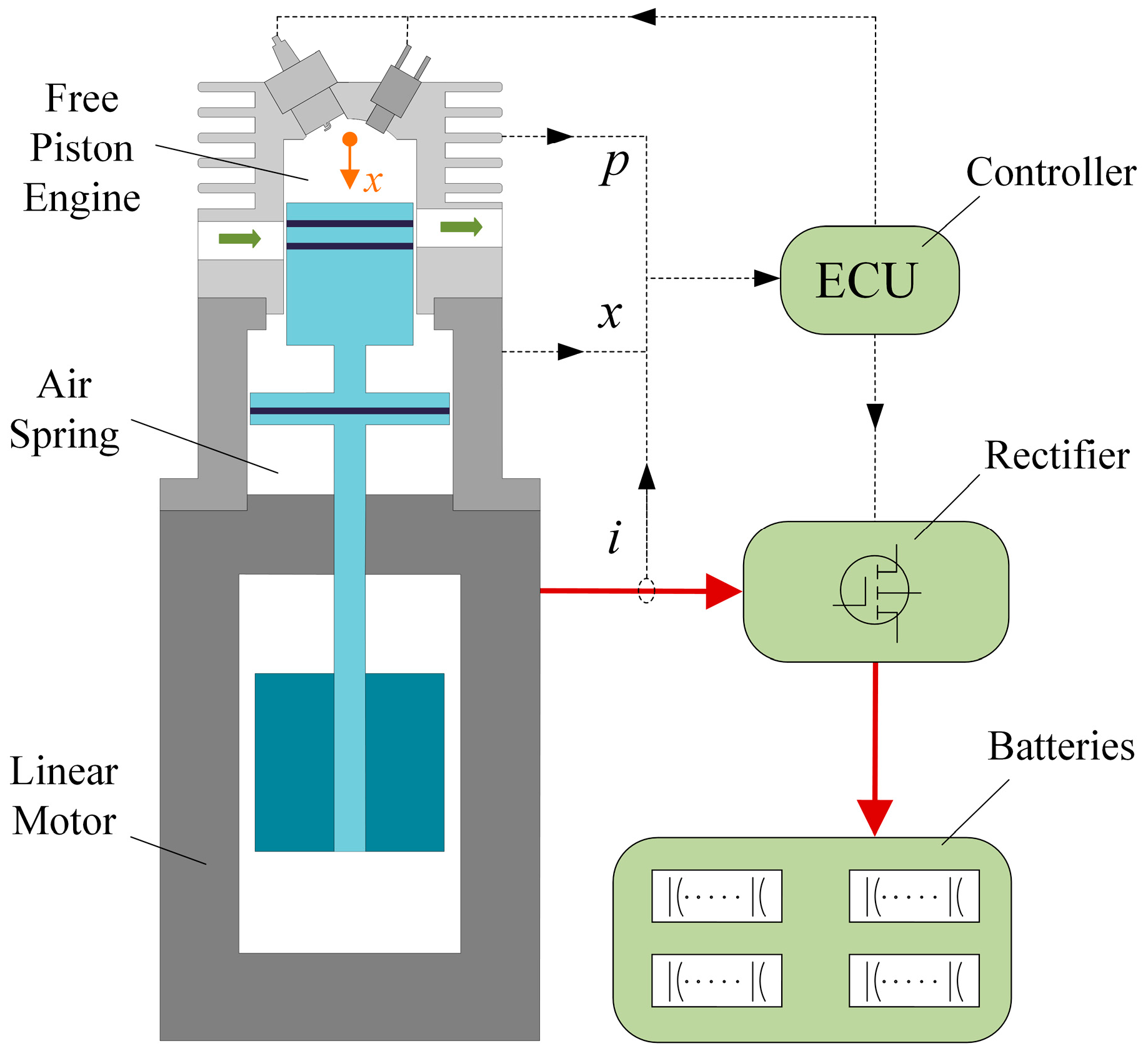
2. System Design
2.1. Linear Motor Design
2.2. Rectifier Design
3. Modeling and Validation
3.1. Linear Motor Model
3.2. Combined Simulation Model
3.3. Model Validation
4. Electromagnetic Loss Analysis
5. Conclusions
Author Contributions
Funding
Conflicts of Interest
References
- Jia, B.; Zuo, Z.; Tian, G.; Feng, H.; Roskilly, A.P. Development and validation of a free-piston engine generator numerical model. Energy Convers. Manag. 2015, 91, 333–341. [Google Scholar] [CrossRef]
- Hanipah, M.R.; Mikalsen, R.; Roskilly, A.P. Recent commercial free-piston engine developments for automotive applications. Appl. Therm. Eng. 2015, 75, 493–503. [Google Scholar] [CrossRef]
- Woo, Y.; Lee, Y.J. Free piston engine generator: Technology review and an experimental evaluation with hydrogen fuel. Int. J. Automot. Technol. 2014, 15, 229–235. [Google Scholar] [CrossRef]
- Yang, L.; Xu, Z.; Liu, L.; Liu, N.; Yu, H. A Tubular PM linear generator with a coreless moving-coil for free-piston engines. IEEE Trans. Energy Convers. 2019, 34, 1309–1316. [Google Scholar] [CrossRef]
- Yan, L.; Zhang, L.; Jiao, Z.; Hu, H. Armature reaction field and inductance of coreless moving-coil tubular linear machine. IEEE Trans. Ind. Electron. 2014, 61, 6956–6965. [Google Scholar] [CrossRef]
- Tan, C.; Li, B.; Ge, W. Thermal quantitative analysis and design method of bi-stable permanent magnet actuators Based on multi-physics methodology. IEEE Trans. Ind. Electron. 2019. [Google Scholar] [CrossRef]
- Yu, X.; Li, B.; Zhang, T. Variable weight coefficient optimization of gearshift actuator with direct-driving automated transmission. IEEE Access 2020, 8, 4860–4869. [Google Scholar] [CrossRef]
- Wang, J.; West, M.; Howe, D.; Parra, H.; Arshad, W. Design and experimental verification of a linear permanent magnet generator for a free-piston energy converter. IEEE Trans. Energy Convers. 2007, 22, 299–306. [Google Scholar] [CrossRef]
- Xu, Z.; Chang, S. Improved moving coil electric machine for internal combustion linear generator. IEEE Trans. Energy Convers. 2010, 25, 281–286. [Google Scholar]
- Chen, H.; Liang, K.; Nie, R.; Liu, X. Three dimensional electromagnetic analysis of tubular permanent magnet linear launcher. IEEE Trans. Appl. Supercond. 2018, 28, 1–6. [Google Scholar] [CrossRef]
- Zheng, P.; Tong, C.; Bai, J.; Yu, B.; Sui, Y.; Shi, W. Electromagnetic design and control strategy of an axially magnetized permanent-magnet linear alternator for free-piston Stirling engines. IEEE Trans. Ind. Electron. 2012, 48, 2230–2239. [Google Scholar] [CrossRef]
- Xu, Y.; Zhao, D.; Wang, Y.; Ai, M. Electromagnetic characteristics of permanent magnet linear generator (PMLG) applied to free-piston engine (FPE). IEEE Access 2019, 7, 48013–48023. [Google Scholar] [CrossRef]
- Chen, H.; Zhao, S.; Wang, H.; Nie, R. A novel single-phase tubular permanent magnet linear generator. IEEE Trans. Appl. Supercond. 2020, 30. [Google Scholar] [CrossRef]
- Park, M.; Choi, J.; Shin, H.; Lee, K. Electromagnetic analysis and experimental testing of a tubular linear synchronous machine with a double-sided axially magnetized permanent magnet mover and coreless stator windings by using semi-analytical techniques. IEEE Trans. Magn. 2014, 50, 1–4. [Google Scholar] [CrossRef]
- Shin, K.; Jung, K.; Cho, H.; Choi, J. Analytical modeling and experimental verification for electromagnetic analysis of tubular linear synchronous machines with axially magnetized permanent magnets and flux-passing iron poles. IEEE Trans. Magn. 2018, 99, 1–6. [Google Scholar] [CrossRef]
- Yan, H.; Xu, Z.; Lu, J.; Liu, D.; Jiang, X. A reciprocating motion control strategy of single-cylinder free-piston engine generator. Electronics 2020, 9, 245. [Google Scholar] [CrossRef]
- Lu, J.; Xu, Z.; Liu, D.; Liu, L. A Starting control strategy of single-cylinder two-stroke free-piston engine generator. J. Eng. Gas Turbines Power 2020, 142, 1–11. [Google Scholar] [CrossRef]


| Items | Value |
|---|---|
| Diameter of outer stator | 114 mm |
| Thickness of outer stator | 12 mm |
| Diameter of inner stator | 68 mm |
| Thickness of inner stator | 24 mm |
| Length of core | 15 mm |
| Length of PM | 30 mm |
| Length of coil area | 37 mm |
| Width of air gap | 10 mm |
| Turns of two coils | 128 |
| Max stroke | 40 mm |
| Items | Value |
|---|---|
| Rated voltage of the battery | 120 V |
| Capacitance of filter capacitor | 400 F |
| Max Current of K1~K4 | 70 A |
| On-resistance of K1~K4 | 25.5 m |
| Turn-on time of K1~K4 | 24 ns |
| Rise time of K1~K4 | 16 ns |
| Turn-off time of K1~K4 | 62 ns |
| Fall time of K1~K4 | 45 ns |
| Diode forward voltage of K1~K4 | 1.3 V |
| PWM Frequency of K1~K4 | 40 kHz |
| Name | Value |
|---|---|
| Rated motion frequency | 50 Hz |
| Rated motion stroke | 36 mm |
| Rated output power | 540 W |
| Mass of the mover | 1.2 kg |
| Efficiency of the linear motor | 91.6% |
| Efficiency of the rectifier | 94.1% |
| Efficiency of the motor system | 86.3% |
| Specific power of the motor | 118 W/kg |
© 2020 by the authors. Licensee MDPI, Basel, Switzerland. This article is an open access article distributed under the terms and conditions of the Creative Commons Attribution (CC BY) license (http://creativecommons.org/licenses/by/4.0/).
Share and Cite
Hu, Y.; Xu, Z.; Yang, L.; Liu, L. Electromagnetic Loss Analysis of a Linear Motor System Designed for a Free-Piston Engine Generator. Electronics 2020, 9, 621. https://doi.org/10.3390/electronics9040621
Hu Y, Xu Z, Yang L, Liu L. Electromagnetic Loss Analysis of a Linear Motor System Designed for a Free-Piston Engine Generator. Electronics. 2020; 9(4):621. https://doi.org/10.3390/electronics9040621
Chicago/Turabian StyleHu, Yunqin, Zhaoping Xu, Lijie Yang, and Liang Liu. 2020. "Electromagnetic Loss Analysis of a Linear Motor System Designed for a Free-Piston Engine Generator" Electronics 9, no. 4: 621. https://doi.org/10.3390/electronics9040621
APA StyleHu, Y., Xu, Z., Yang, L., & Liu, L. (2020). Electromagnetic Loss Analysis of a Linear Motor System Designed for a Free-Piston Engine Generator. Electronics, 9(4), 621. https://doi.org/10.3390/electronics9040621