Prioritized Uplink Resource Allocation in Smart Grid Backscatter Communication Networks via Deep Reinforcement Learning

 ,
, 
Abstract
1. Introduction
2. Related Work
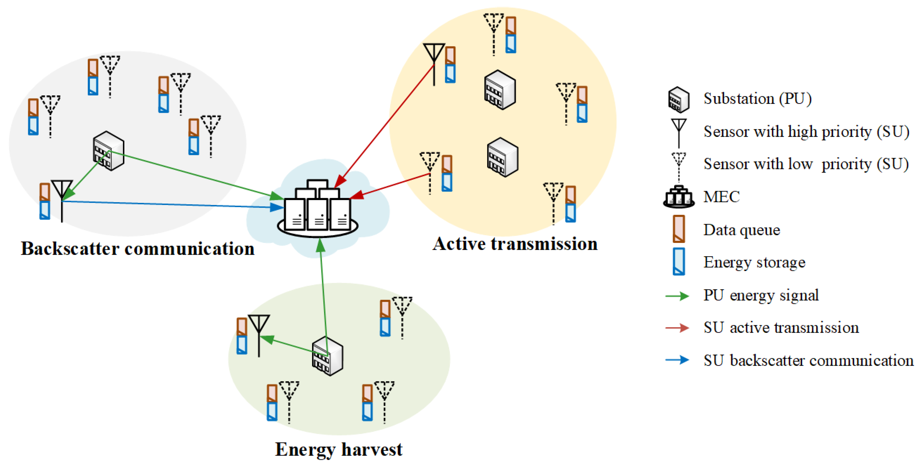
3. System Model
3.1. Multi-User Backscatter Communication Network in CR-Based Smart Grid
3.2. User Scheduling Based on Priority
3.3. Problem Formulation
4. Resource Allocation Policy
4.1. K-Means Clustering
4.1.1. Algorithm Description
| Algorithm 1: K-Means Algorithm for BDs Clustering. |
 |
4.1.2. Clustering Evaluation
4.2. Deep Reinforcement Learning Algorithm
| Algorithm 2: A3C-based Resource Allocation Algorithm. |
 |
5. Performance Evaluation
5.1. Simulation Setting
5.2. Convergence Evaluation
5.3. Adaptability to Environment
5.4. Priority Policy Evaluation
6. Conclusions and Future Research
Author Contributions
Funding
Conflicts of Interest
References
- Zhang, Y.; Li, X.; Zhang, S.; Zhen, Y. Wireless sensor network in smart grid: Applications and issue. In Proceedings of the 2012 World Congress on Information and Communication Technologies, Trivandrum, India, 30 October–2 November 2012; pp. 1204–1208. [Google Scholar]
- Abu Alsheikh, M.; Hoang, D.T.; Niyato, D.; Tan, H.; Lin, S. Markov Decision Processes with Applications in Wireless Sensor Networks: A Survey. IEEE Commun. Surv. Tutor. 2015, 17, 1239–1267. [Google Scholar] [CrossRef]
- Choi, S.H.; Kim, D.I. Backscatter radio communication for wireless powered communication networks. In Proceedings of the 2015 21st Asia-Pacific Conference on Communications (APCC), Kyoto, Japan, 14–15 October 2015; pp. 370–374. [Google Scholar]
- Kwan, J.C.; Fapojuwo, A.O. Sum-Throughput Maximization in Wireless Sensor Networks with Radio Frequency Energy Harvesting and Backscatter Communication. IEEE Sens. J. 2018, 18, 7325–7339. [Google Scholar] [CrossRef]
- Hoang, D.T.; Niyato, D.; Wang, P.; Kim, D.I.; Han, Z. Ambient Backscatter: A New Approach to Improve Network Performance for RF-Powered Cognitive Radio Networks. IEEE Trans. Commun. 2017, 65, 3659–3674. [Google Scholar] [CrossRef]
- Zhang, W.; Qin, Y.; Zhao, W.; Jia, M.; Liu, Q.; He, R.; Ai, B. A green paradigm for Internet of Things: Ambient backscatter communications. China Commun. 2019, 16, 109–119. [Google Scholar]
- Yang, G.; Yuan, D.; Liang, Y. Optimal Resource Allocation in Full-Duplex Ambient Backscatter Communication Networks for Green IoT. In Proceedings of the 2018 IEEE Global Communications Conference (GLOBECOM), Abu Dhabi, UAE, 9–13 December 2018. [Google Scholar]
- Li, J.; Xu, J.; Gong, S.; Li, C.; Niyato, D. A Game Theoretic Approach for Backscatter-Aided Relay Communications in Hybrid Radio Networks. In Proceedings of the 2018 IEEE Global Communications Conference (GLOBECOM), Abu Dhabi, UAE, 9–13 December 2018. [Google Scholar]
- Huynh, N.V.; Hoang, D.T.; Nguyen, D.N.; Dutkiewicz, E.; Niyato, D.; Wang, P. Reinforcement Learning Approach for RF-Powered Cognitive Radio Network with Ambient Backscatter. In Proceedings of the 2018 IEEE Global Communications Conference (GLOBECOM), Abu Dhabi, UAE, 9–13 December 2018. [Google Scholar]
- Anh, T.T.; Luong, N.C.; Niyato, D.; Liang, Y.; Kim, D.I. Deep Reinforcement Learning for Time Scheduling in RF-Powered Backscatter Cognitive Radio Networks. In Proceedings of the 2019 IEEE Wireless Communications and Networking Conference (WCNC), Marrakesh, Morocco, 6–9 April 2019. [Google Scholar]
- Zhang, Q.; Zhang, L.; Liang, Y.; Kam, P.Y. Backscatter-NOMA: An Integrated System of Cellular and Internet-of-Things Networks. In Proceedings of the ICC 2019—2019 IEEE International Conference on Communications (ICC), Shanghai, China, 20–24 May 2019. [Google Scholar]
- Darsena, D.; Gelli, G.; Verde, F. Cloud-Aided Cognitive Ambient Backscatter Wireless Sensor Networks. IEEE Access 2019, 7, 57399–57414. [Google Scholar] [CrossRef]
- Yang, G.; Zhang, Q.; Liang, Y. Cooperative Ambient Backscatter Communications for Green Internet-of-Things. IEEE Internet Things J. 2018, 5, 1116–1130. [Google Scholar] [CrossRef]
- Gao, X.; Feng, S.; Niyato, D.; Wang, P.; Yang, K.; Liang, Y. Dynamic Access Point and Service Selection in Backscatter-Assisted RF-Powered Cognitive Networks. IEEE Internet Things J. 2019, 6, 8270–8283. [Google Scholar] [CrossRef]
- Lyu, B.; Yang, Z.; Gui, G.; Feng, Y. Wireless Powered Communication Networks Assisted by Backscatter Communication. IEEE Access 2017, 5, 7254–7262. [Google Scholar] [CrossRef]
- Hoang, D.T.; Niyato, D.; Wang, P.; Kim, D.I.; Le, L.B. Overlay RF-powered backscatter cognitive radio networks: A game theoretic approach. In Proceedings of the 2017 IEEE International Conference on Communications (ICC), Paris, France, 21–25 May 2017. [Google Scholar]
- Lyu, B.; Guo, H.; Yang, Z.; Gui, G. Throughput Maximization for Hybrid Backscatter Assisted Cognitive Wireless Powered Radio Networks. IEEE Internet Things J. 2018, 5, 2015–2024. [Google Scholar] [CrossRef]
- Wang, P.; Wang, N.; Dabaghchian, M.; Zeng, K.; Yan, Z. Optimal Resource Allocation for Secure Multi-User Wireless Powered Backscatter Communication with Artificial Noise. In Proceedings of the IEEE INFOCOM 2019—IEEE Conference on Computer Communications, Paris, France, 29 April–2 May 2019; pp. 460–468. [Google Scholar]
- Xiao, S.; Guo, H.; Liang, Y. Resource Allocation for Full-Duplex-Enabled Cognitive Backscatter Networks. IEEE Trans. Wirel. Commun. 2019, 18, 3222–3235. [Google Scholar] [CrossRef]
- Rahmati, A.; Dai, H. Reinforcement Learning for Interference Avoidance Game in RF-Powered Backscatter Communications. In Proceedings of the ICC 2019—2019 IEEE International Conference on Communications (ICC), Shanghai, China, 20–24 May 2019. [Google Scholar]
- Hu, Y.; Wang, P.; Lin, Z.; Ding, M.; Liang, Y. Machine Learning Based Signal Detection for Ambient Backscatter Communications. In Proceedings of the ICC 2019—2019 IEEE International Conference on Communications (ICC), Shanghai, China, 20–24 May 2019. [Google Scholar]
- Van Huynh, N.; Hoang, D.T.; Nguyen, D.N.; Dutkiewicz, E.; Niyato, D.; Wang, P. Optimal and Low-Complexity Dynamic Spectrum Access for RF-Powered Ambient Backscatter System with Online Reinforcement Learning. IEEE Trans. Commun. 2019, 67, 5736–5752. [Google Scholar] [CrossRef]
- Wen, X.; Bi, S.; Lin, X.; Yuan, L.; Wang, J. Throughput Maximization for Ambient Backscatter Communication: A Reinforcement Learning Approach. In Proceedings of the 2019 IEEE 3rd Information Technology, Networking, Electronic and Automation Control Conference (ITNEC), Chengdu, China, 15–17 March 2019; pp. 997–1003. [Google Scholar]
- Xie, Y.; Xu, Z.; Zhong, Y.; Xu, J.; Gong, S.; Wang, Y. Backscatter-Assisted Computation Offloading for Energy Harvesting IoT Devices via Policy-based Deep Reinforcement Learning. In Proceedings of the 2019 IEEE/CIC International Conference on Communications Workshops in China (ICCC Workshops), Changchun, China, 11–13 August 2019; pp. 65–70. [Google Scholar]
- Lyu, B.; You, C.; Yang, Z.; Gui, G. The Optimal Control Policy for RF-Powered Backscatter Communication Networks. IEEE Trans. Veh. Technol. 2018, 67, 2804–2808. [Google Scholar] [CrossRef]
- Nguyen, N.; Van Huynh, N.; Hoang, D.T.; Nguyen, D.N.; Nguyen, N.; Nguyen, Q.; Dutkiewicz, E. Energy Management and Time Scheduling for Heterogeneous IoT Wireless-Powered Backscatter Networks. In Proceedings of the ICC 2019—2019 IEEE International Conference on Communications (ICC), Shanghai, China, 20–24 May 2019. [Google Scholar]
- Liu, V.; Parks, A.; Talla, V.; Gollakota, S.; Wetherall, D.; Smith, J.R. Ambient backscatter: Wireless communication out of thin air. ACM SIGCOMM Comput. Commun. Rev. 2013, 43, 39–50. [Google Scholar] [CrossRef]
- Psomas, C.; Krikidis, I. Collision avoidance in wireless powered sensor networks with backscatter communications. In Proceedings of the 2017 IEEE 18th International Workshop on Signal Processing Advances in Wireless Communications (SPAWC), Sapporo, Japan, 3–6 July 2017. [Google Scholar]


| Parameters | Values |
|---|---|
| The maximum length of date queue | 10 packets |
| The maximum capacity of energy | 10 units |
| The amount of data in each packets | 1 kbit |
| The probability of packet arrival | 0.9 |
| The probability that the channel is idle | 0.5 |
| The probability of an emergency | 0.5 |
| Number of packets transmitted per unit time in backscatter communication () | 1 packet |
| Number of packets transmitted per unit time in active transmission () | 2 packets |
| Number of energy harvest per unit time () | 1 unit |
| Number of energy consumption per unit time () | 1 unit |
| Discount factor () | 0.9 |
| The maximun length of episode | 1000 |
| The length of episode to update global network parameters | 10 |
| Network learning rate | 0.001 |
| Number of hidden layers | 1 |
| Activation | Relu |
| Optimizer | RMSPropOptimizer |
© 2020 by the authors. Licensee MDPI, Basel, Switzerland. This article is an open access article distributed under the terms and conditions of the Creative Commons Attribution (CC BY) license (http://creativecommons.org/licenses/by/4.0/).
Share and Cite
Yang, Z.; Feng, L.; Chang, Z.; Lu, J.; Liu, R.; Kadoch, M.; Cheriet, M. Prioritized Uplink Resource Allocation in Smart Grid Backscatter Communication Networks via Deep Reinforcement Learning. Electronics 2020, 9, 622. https://doi.org/10.3390/electronics9040622
Yang Z, Feng L, Chang Z, Lu J, Liu R, Kadoch M, Cheriet M. Prioritized Uplink Resource Allocation in Smart Grid Backscatter Communication Networks via Deep Reinforcement Learning. Electronics. 2020; 9(4):622. https://doi.org/10.3390/electronics9040622
Chicago/Turabian StyleYang, Zhixiang, Lei Feng, Zhengwei Chang, Jizhao Lu, Rongke Liu, Michel Kadoch, and Mohamed Cheriet. 2020. "Prioritized Uplink Resource Allocation in Smart Grid Backscatter Communication Networks via Deep Reinforcement Learning" Electronics 9, no. 4: 622. https://doi.org/10.3390/electronics9040622
APA StyleYang, Z., Feng, L., Chang, Z., Lu, J., Liu, R., Kadoch, M., & Cheriet, M. (2020). Prioritized Uplink Resource Allocation in Smart Grid Backscatter Communication Networks via Deep Reinforcement Learning. Electronics, 9(4), 622. https://doi.org/10.3390/electronics9040622