Article

Design of a Cylindrical Winding Structure for Wireless Power Transfer Used in Rotatory Applications

School of Electrical Engineering, Xi’an Jiaotong University, Xi’an 710049, China
*
Author to whom correspondence should be addressed.
Electronics 2020, 9(3), 526; https://doi.org/10.3390/electronics9030526
Submission received: 26 February 2020 / Revised: 15 March 2020 / Accepted: 19 March 2020 / Published: 23 March 2020
(This article belongs to the Special Issue Wireless Power/Data Transfer, Energy Harvesting System Design)

Abstract

:
A cylindrical joint structure for wireless power transfer (WPT) systems is proposed. The transmitter (Tx) and receiver (Rx) coils were wound on hemicylindrical and cylindrical structures, respectively. The Rx coil rotates freely around the axial direction of the Tx coil. Different methods of winding the Tx and Rx coils are given and discussed. Electromagnetic fields (EMFs) around the WPT windings should be lower than the limits set by WPT standards. Therefore, the WPT windings were designed to reduce EMF level and maintain constant power-transfer efficiency (PTE). The design procedures of the windings are discussed in detail. EMF analysis was done under different rotation angles (α). The selected design reduced the variation of the mutual inductance (M). As a result, it maintained a constant PTE while rotating the Rx coil between 0° and 85°. Moreover, leakage magnetic fields (LMFs) near the WPT coils of the chosen design were reduced by 63.6% compared with other winding methods that have the same efficiency. Finally, a prototype was built to validate the proposed idea. Experiment results were in good agreement with the simulation results. The WPT system maintained constant efficiency in spite of the rotation of Rx coil, where efficiency dropped by only 2.15% when the Rx coil rotated between 0° and 85°.

Graphical Abstract

1. Introduction

Wireless power transfer (WPT) systems have proven their reliability and have become a widely used technique. A WPT system transfers power for many applications, such as implantable medical devices (IMDs) [1,2,3], the charging of electric vehicles (EVs) [4,5,6,7,8,9], autonomous underwater vehicles (AUVs) [10], unmanned aerial vehicles (UAV) [11], robotic systems [12], light detection and ranging equipment [13], and the Internet of Things (IoT) [14,15,16]. In addition, it is used in some appliances, for instance, smartwatch straps [17], smartphones [18], battery-powering systems [19], and electrical drones [20,21]. Earlier, many research works investigated different types of structures, such as pancake coils, square coils, and circular coils [22,23]. Recently, in order to extend the transfer area, three-dimensional (3D) geometries have been proposed. For example, a rectangle-shaped resonant cavity was presented [1]. It charged multiple IMDs in a freely behaving animal. A WPT system made of a bowl-shaped transmitter (Tx) coil and a box-shaped receiver (Rx) coil was investigated and could be embedded in an in-ear hearing aid [24]. Hou, et al. [25] fabricated 3D windings for the WPT system. Moreover, Ha-Van et al. [26] studied an omnidirectional WPT system with a cube-shaped Tx coil that could be a possible way of charging portable devices. Many other structures were reported in [27]. However, those structures only considered fixed coils without built-in rotatory parts.
Therefore, recent studies have considered the rotation of the coils to improve WPT performance and maintain constant output power. Yan et al. [10] presented a rotation-free WPT system for AUV charging. Zhang et al. [28] designed a ball-joint WPT system. The joint consisted of a small ball that was rotated inside a socket structure. Houran et al. [29] investigated a spherical-joint structure that was made of a small ball that rotated inside a hemisphere structure. Han et al. [30] discussed a rotatory WPT system for multiload applications. Sugino et al. [12] fabricated a linear-free motion WPT used in robotic applications. These references provided good contributions to the development of the WPT winding study. Further development is given in this paper, where the coils are optimized for low electromagnetic fields (EMFs) and high power-transfer efficiency (PTE) regardless of angular rotation.
On the other hand, compliance with EMF safety regulations and standards is a main concern regarding the design of the WPT system [31]. If the coupling coefficient (k) has low values, it will create high levels of leakage magnetic fields (LMFs) in the windings’ vicinities. Thus, there is an exposure to EMFs for anyone who approaches the application during charging [32]. In addition, using the WPT charging systems next to other electronic devices could create electromagnetic field interference (EMI). To comply with standards and regulations, such as the International Commission on Nonionizing Radiation Protection (ICNIRP) 2010 [33], many EMF- and EMI-reduction methods have been presented. For example, using ferrite [31], metamaterials [34,35,36], and reducing LMFs by three-phase power [37]. Moreover, in [38], the authors presented three active shielding methods: three-dB dominant EMF cancellation (3DEC), independent self-EMF cancellation (ISEC), and linkage-free EMF cancellation (LFEC). In [18], the authors presented resonant reactive shields for a planar WPT system. The above-mentioned methods require additional components, such as coils, power supplies, and capacitors. In addition, choosing an applicable EMF mitigation method depends on several important factors, for example, application type, available space, weight, and cost. However, in order to reduce LMFs, it is better to reduce the source of LMFs and optimize the coils.
In this paper, a new joint structure is proposed. The main contributions are as follows. (1) A moveable WPT winding structure is proposed that combines a hemicylindrical-structure Tx coil and a cylindrical-structure Rx coil. By means of the proposed structure, the Rx coil could rotate inside the Tx coil within angles of up to 85°. (2) A detailed design procedure of the proposed structure is introduced. It includes the design of the windings, electromagnetic-field assessment, and necessary simulations. (3) The Tx and Rx coils were designed in order to minimize the leakage of magnetic fields around the coils’ vicinities and maintain high power-transfer efficiency (PTE). Furthermore, EMF analysis was done under different rotation angles. (4) A prototype of the WPT coils was fabricated and measurements were done. Efficiency was almost constant under different rotation angles.
The rest of this paper is organized as follows. In Section 2, a detailed description of the proposed structure is given. In Section 3, design procedures of the WPT system for high efficiency are presented. Design procedures of the WPT system for low-leakage magnetic fields are given in Section 4. Experiment results are shown in Section 5 in order to validate the proposed structure. Section 6 concludes this paper.

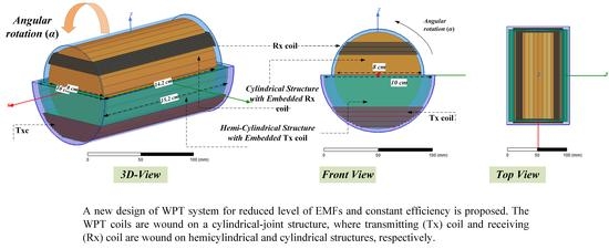
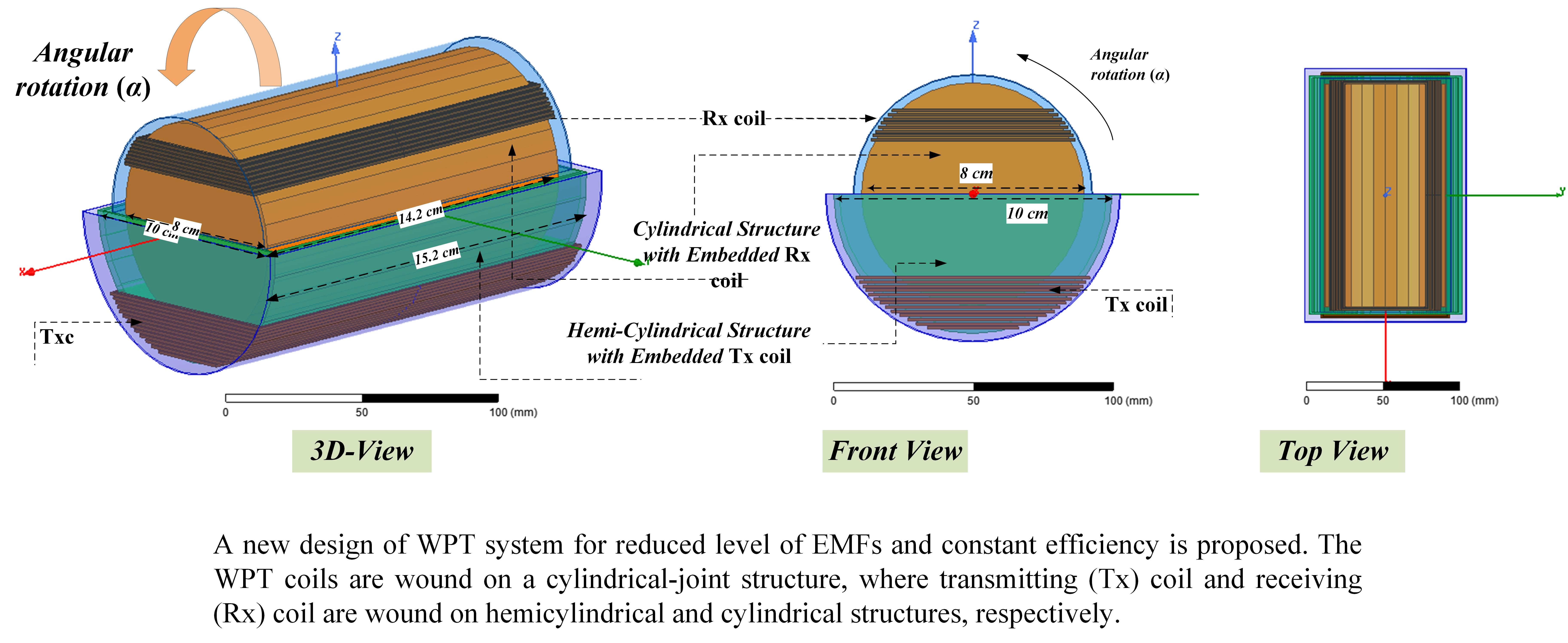
2. Design of Proposed WPT System

The design of the cylindrical joint of the WPT system is shown in Figure 1. In this design, the Rx coil can rotate within the Tx coil up to 85°. The Tx coil (blue) was wound on the hemicylindrical structure, and the Rx coil (brown) was wound on the cylindrical structure.
The transferred power (P) across the gap, given in Equation (1), is proportional to frequency (f), mutual inductance (M), and the square of the Tx current (I2) [28]. The design of the proposed WPT system can be optimized by maximizing the mutual inductance and reducing its fluctuation at different rotation angles (α). Mutual inductance is given by Equation (2).
P f M I 2 2
M = k L T x L R x
where k is the coupling coefficient, LTx is the self-inductance of the Tx coil, and LRx is the self-inductance of the Rx coil. LTx and LRx depend on the resonators’ geometries. Several variables were considered to parametrize the coils, as follows. Turn numbers are given as NTx, NRx, where NTx is the number of turns of Tx coil and NRx is the number of turns of Rx coil. Number of winding layers are given as single-layer (SL) winding and double-layer (DL) winding. In addition, the space between turns and variation in the z-axis position, which affects the value of the coupling coefficient, was considered. Therefore, there are many possibilities for winding Tx and Rx coils on a joint structure.
Some winding models are illustrated in Figure 2. Figure 2a is a hemicylindrical winding method of Tx and Rx coils that can be written as DL (64, 50), where 64 is the number of turns of the Tx coil, and 50 is the number of turns of the Rx coil. Figure 2a–c shows very high coupling coefficients (close to 0.4). In such models, the fluctuation of mutual inductance with rotation is very high. For example, Figure 3 displays the variations of mutual inductance and coupling coefficient of the winding structures that are given in Figure 2c. M variation reached 95% when the Rx coil rotated between 0° and 85°. Therefore, efficiency drops a lot in this case. In addition, a high coupling could result in a frequency-splitting issue, thus reducing output power. For choosing the right model, low variations of mutual inductance while rotating the Rx coil should be considered. Thus, a WPT system maintains constant efficiency. The coupling coefficient between the studied models ranged between 0.08 and 0.5. In further steps, the chosen model should consider low-leakage magnetic fields, which is explained in the next section.

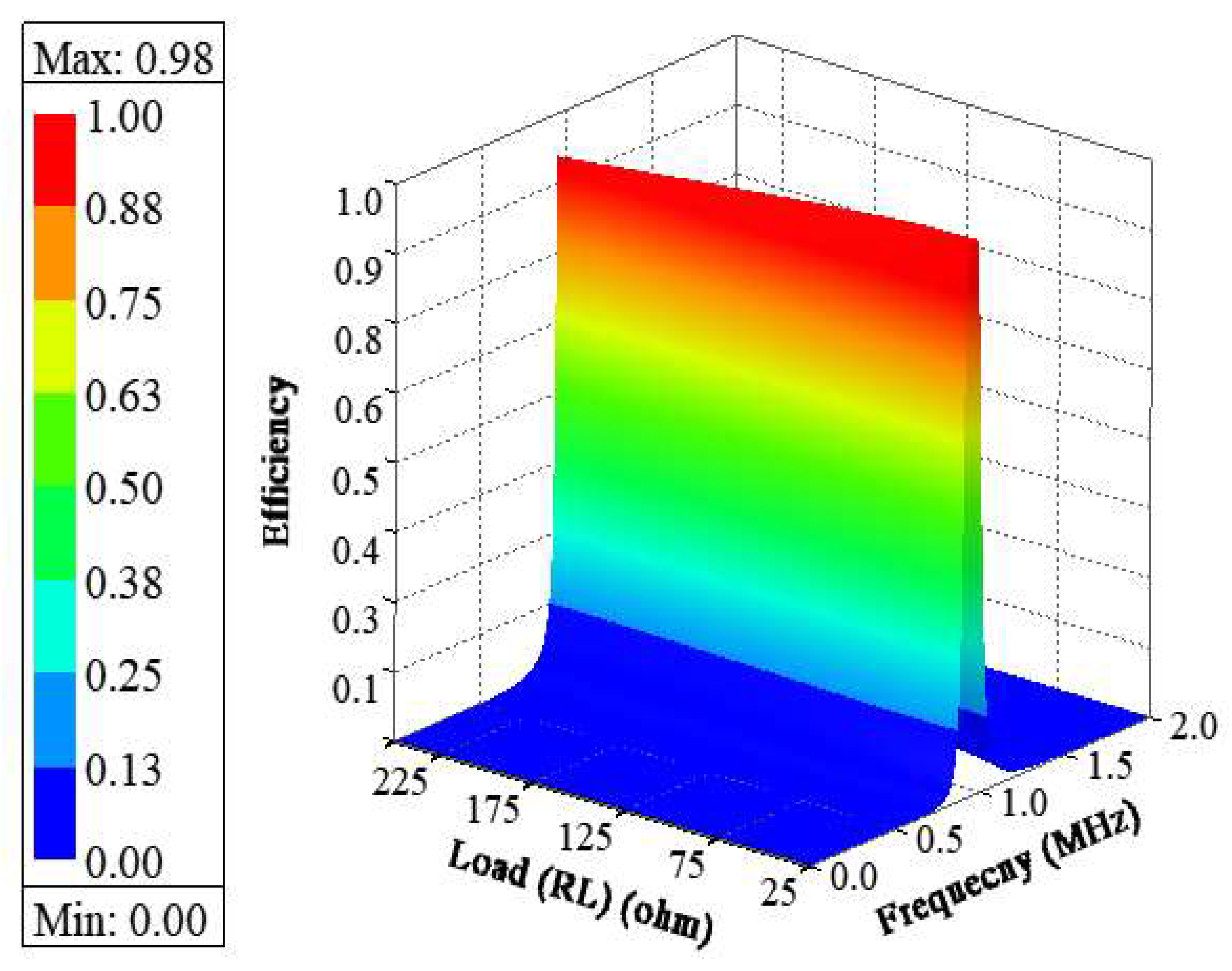
3. Design Procedures for High Efficiency

Different methods of winding the Tx and Rx coils were obtained. In Figure 4, twelve different coil designs are displayed. In Figure 4a, the Tx and Rx coils took the same shape of hemicylindrical structures, and could be denoted as DL (64, 50). In Figure 4h, the Tx and Rx coils took the same shape of hemicylindrical structures and could be denoted as SL (32, 25). As mentioned before, a constant PTE during the rotation of the Rx coil depends on mutual inductance and coupling coefficient, which follows the winding structure. Different methods of winding the Tx and Rx coils resulted in different values of the coupling coefficients and mutual inductances, as illustrated in Figure 5. DL (64, 50) and SL (32, 25) designs had very high values of M and k. However, cost, volume, and weight were higher than those of other models. In addition, for the magnetically coupled resonant (MCR) WPT design, the k value could not be very high. Therefore, the design could be selected as one of the models that are marked in black in Figure 5.
The simulations of the WPT system were conducted with Ansys Maxwell 3D and Ansys Simplorer for cosimulation. Series–series (SS) compensation topology was considered. Resonant frequency was 950 kHz. Figure 6 illustrates the efficiency of each SS-compensated WPT system at a resonant frequency of 950 kHz. On the basis of the value of the coupling coefficient (shown in Figure 5) and the efficiency values in Figure 6, the chosen design was DL (30, 16). Figure 6b displays the DL efficiency (30, 16).
DL (30, 16) self-inductances were LTx1 = 120.68 µH and LRx1 = 52.068 µH. Figure 7 presents the relation between frequency, load, and efficiency, showing that the system was steady at low and high loads.

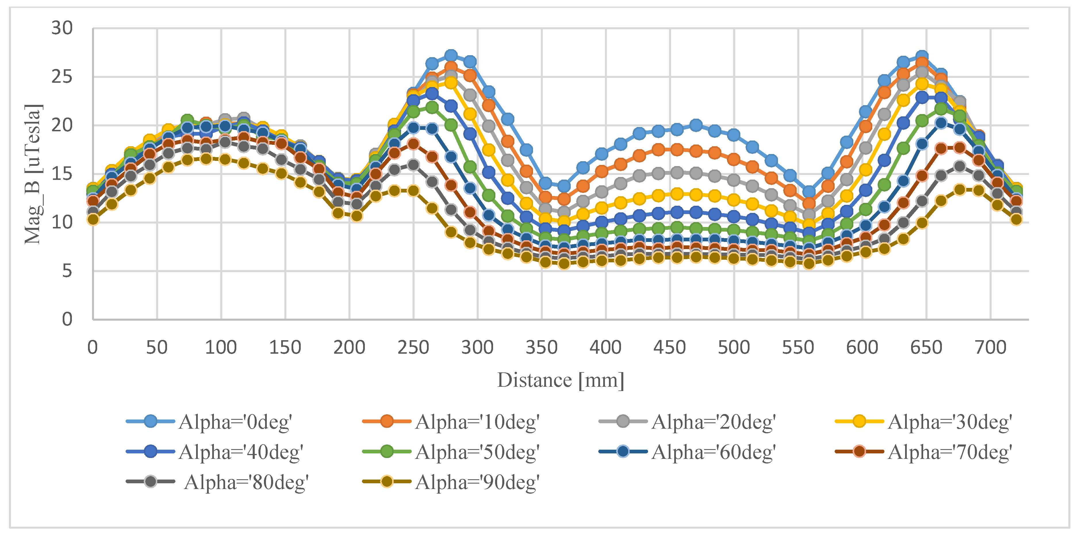
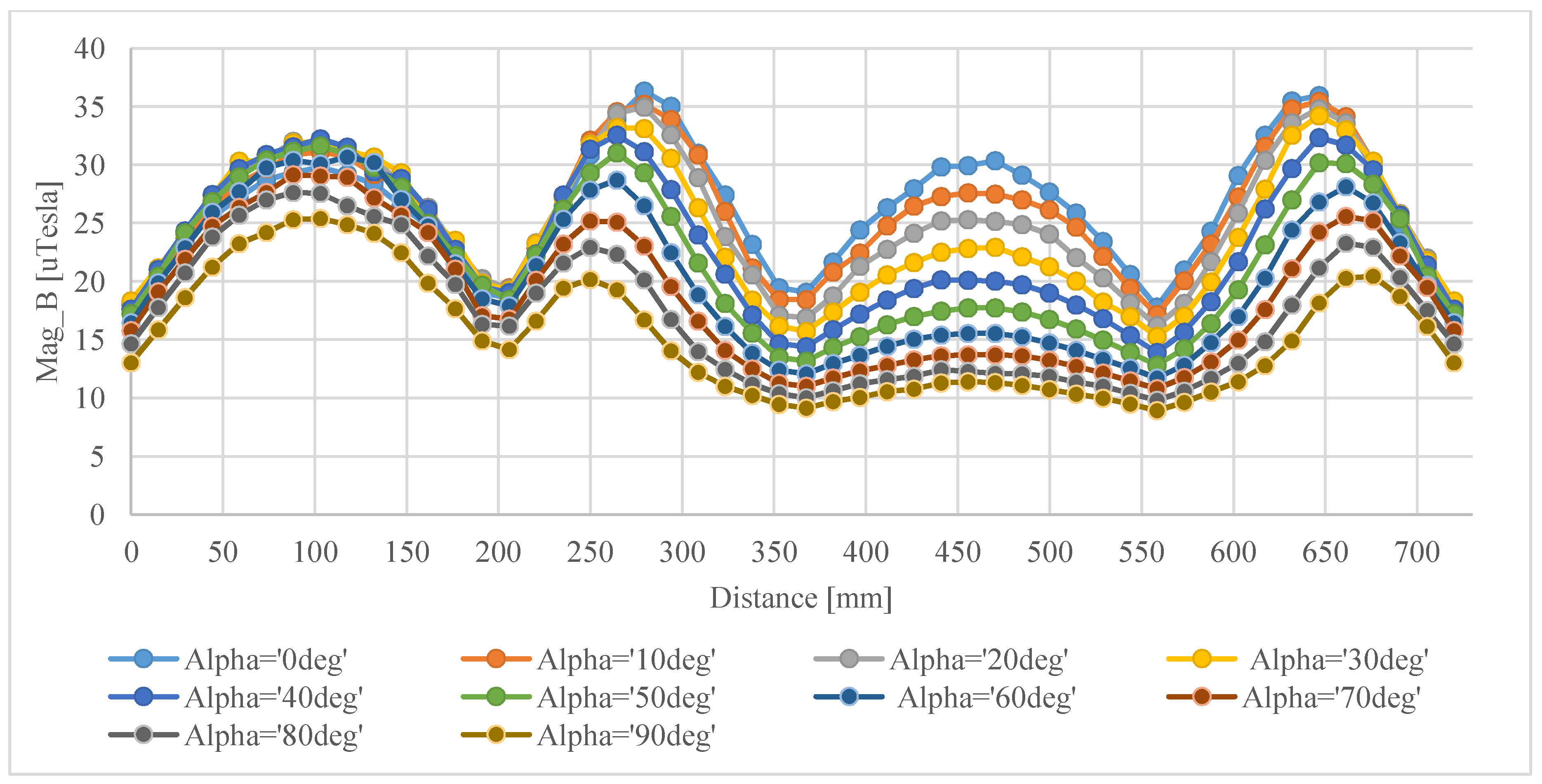
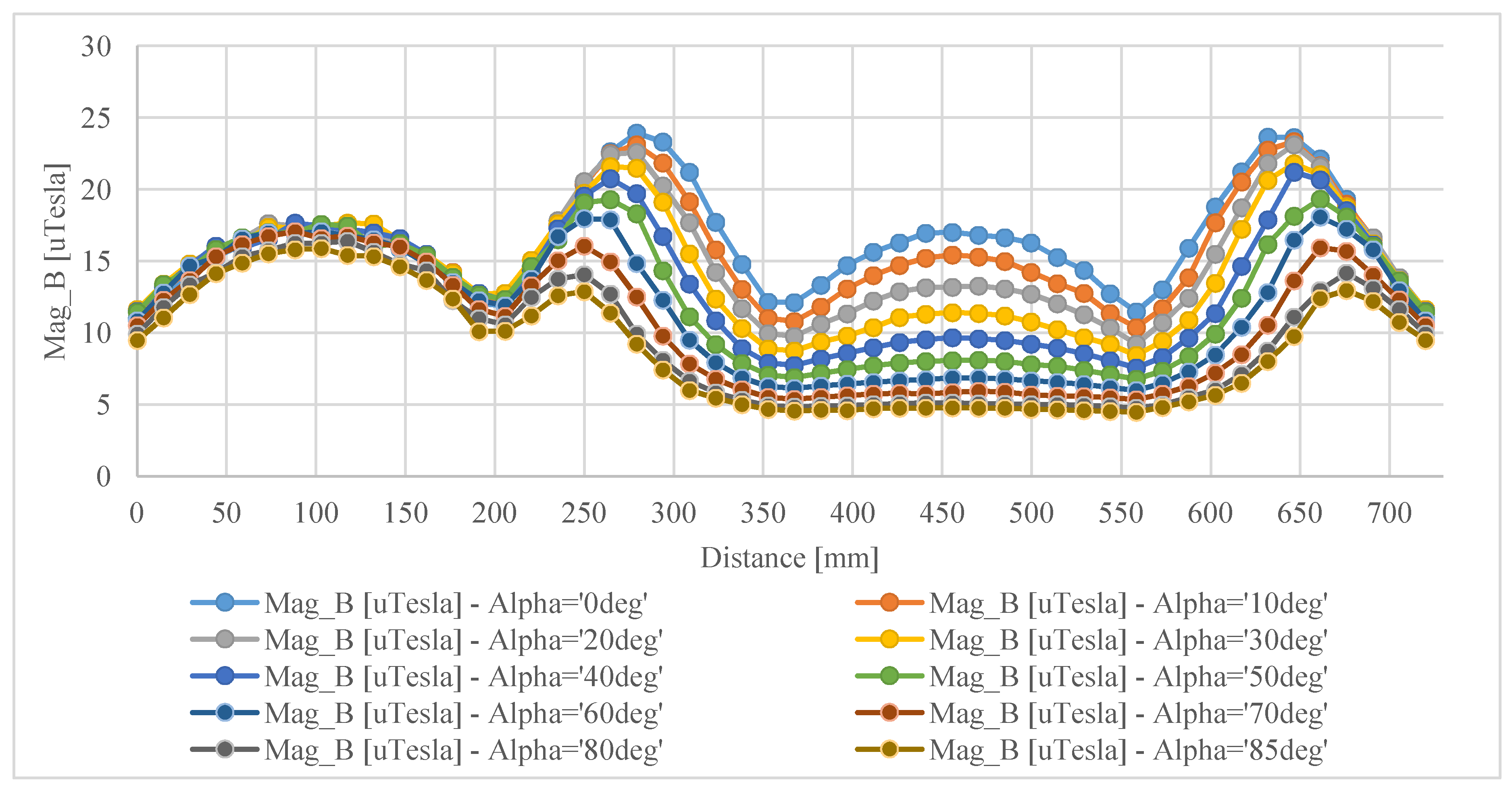
4. Design Procedures for Low-Leakage Magnetic Fields

Maintaining low-leakage magnetic fields (LMFs) around Tx and Rx coils is another key point of WPT design. Figure 8 illustrates a comparison of the magnetic-field density (B) of different WPT systems (given in Figure 4). B was calculated around the coils’ vicinities. The worst winding scenario was DL (64, 50), which had very-high-leakage magnetic fields (LMFs) of 74.67 µT. In addition, DL (64, 50) had a very high value of coupling coefficient at α = 0°, and this value dropped close to zero at α = 85°. On the basis of the efficiency value given in Figure 6, and the magnetic-field-density value presented in Figure 8, the chosen design was the same as DL (30, 16) (dark green), which had a low LMF level of 27.1 µT. This value is almost the same as the exposure limit that was set by ICNIRP-2010. Therefore, the chosen design decreased LMFs by 63.6% compared with DL (64, 50), which has similar efficiency. Moreover, the magnetic-field density of the chosen design at different rotation angles (0°–85°) is illustrated in Figure 9. With the rotation of the Rx coil, B was reduced. Furthermore, Figure 10 displays the B of SL (32, 25). Compared with the best selected design, the level of LMFs was decreased by 22.5%.
There are some models that have almost the same level of LMFs as those of the chosen design, such as DL (24, 16), as shown in Figure 11 at different rotation angles. Nevertheless, on the basis of efficiency values, DL (30, 16) had efficiency of 97.9%, whereas DL (24, 16) had efficiency of 87.1%.

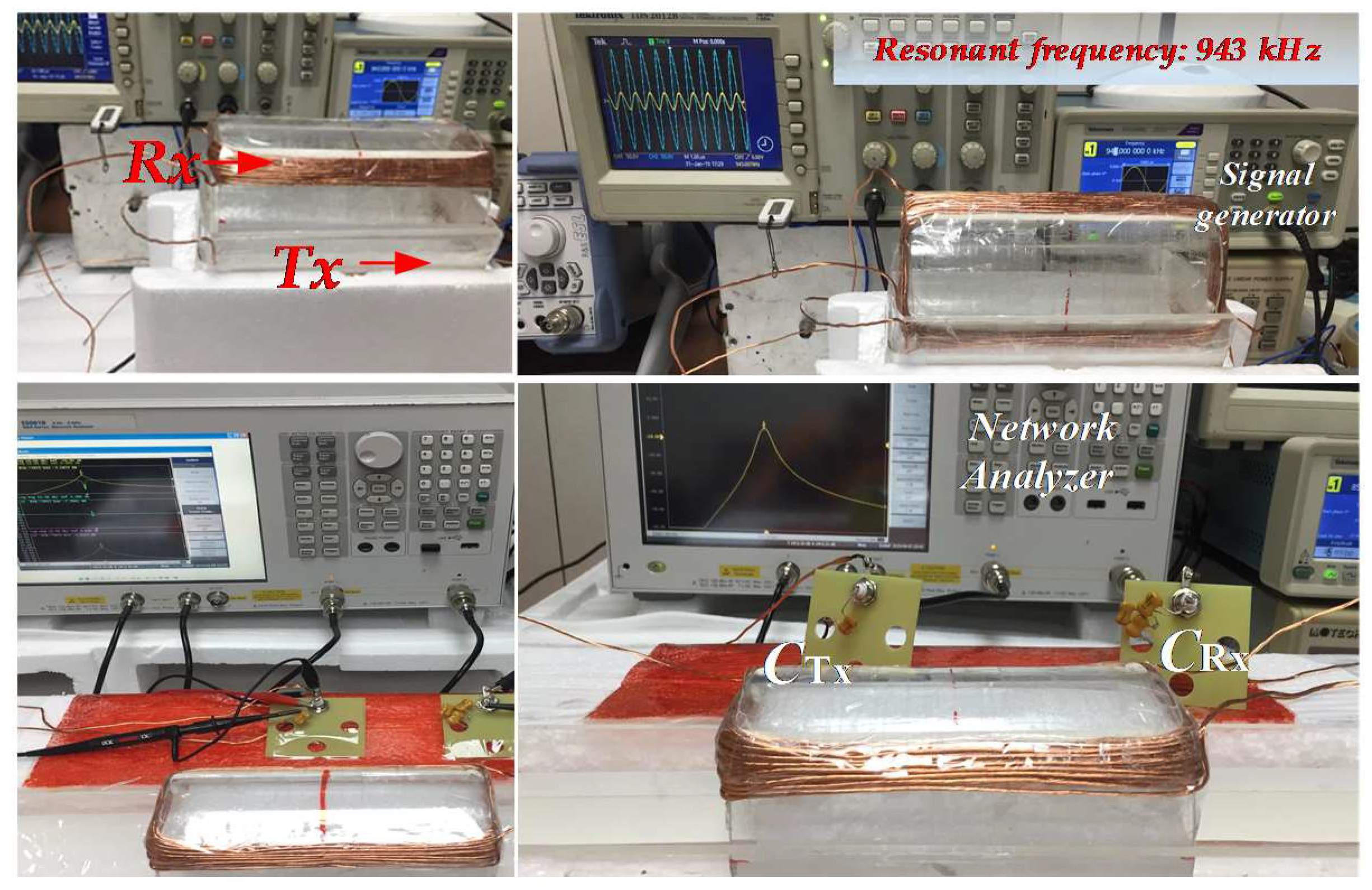
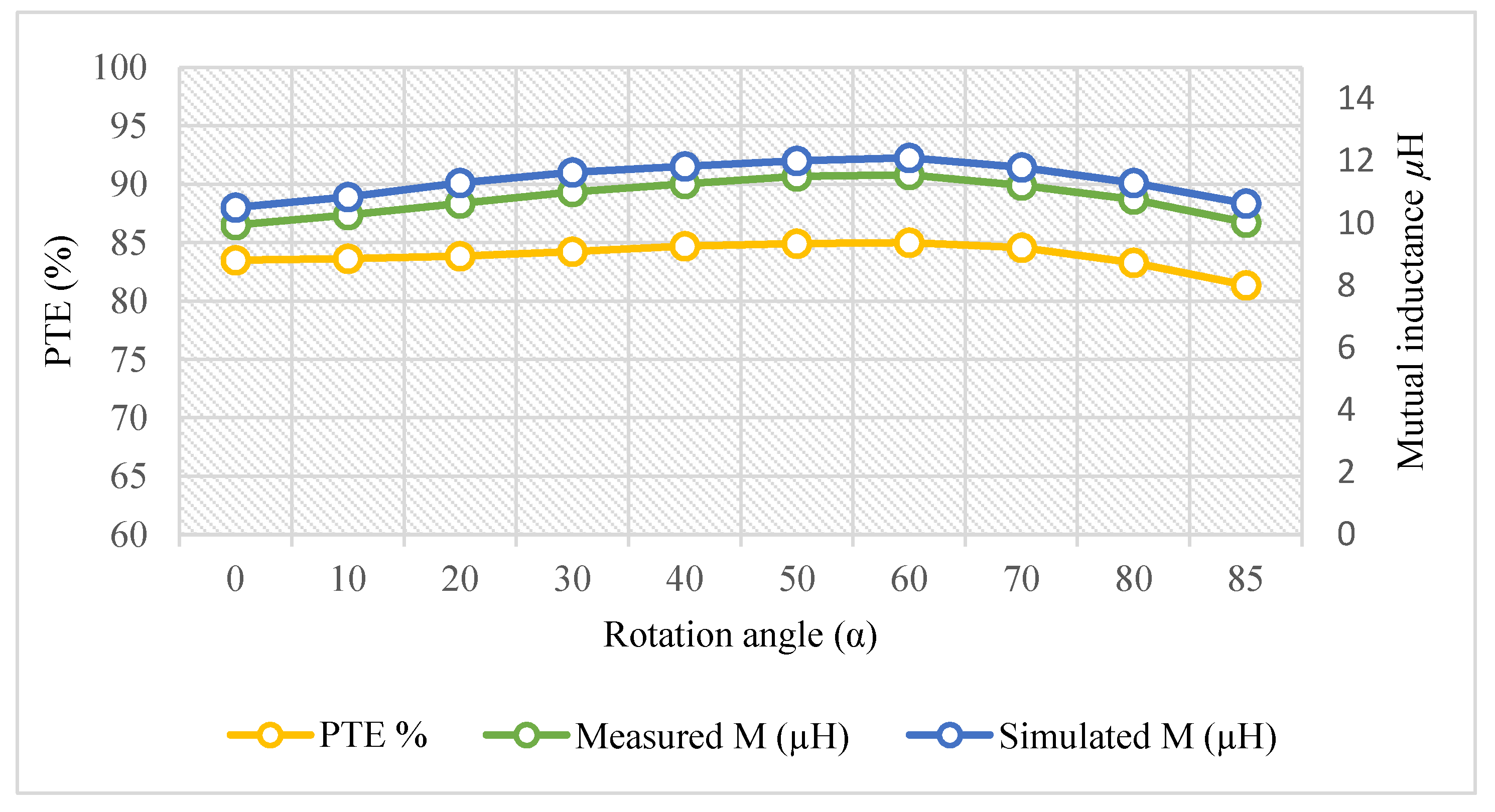
5. Experiment Results and Validation

To validate the selected design (DL (30, 16)), a prototype was built. Series–series (SS) topology was chosen. The experiment setup is given in Figure 12. Multistrand Litz wire was used to wind the coils. This reduced the skin effect and power losses at high frequency. In addition, radio-frequency (RF) mica capacitors were used for better performance of the WPT system. The measured parameters are given in Table 1, where R1 and R2 (Ω) are the resistances of Tx and Rx windings, respectively; and CTx and CRx (nF) are the compensation capacitors of Tx and Rx coils, respectively.
The input and output voltages are displayed in Figure 13. The output voltage slightly changed when Rx coil rotated. The voltages are presented at four angles between 0° and 85°.
The chosen design had low fluctuations of mutual inductance while rotating the Rx coil. The measured and simulated mutual inductances are presented in Figure 14. Simulated mutual inductance is always larger than measured mutual inductance. The simulations gave ideal values of the coils’ inductances and mutual inductance. However, measurements take into consideration some factors such as losses. In addition, in the fabricated prototype, the distance between the Tx and Rx coils was slightly different than that in the simulated model, so the coupling coefficient in the simulation was 0.13, whereas the measured one was 0.11. Therefore, simulated mutual inductance was larger than the measured mutual inductance. The measured M varied between 9.94 µH at α = 0°, 11.56 µH at α = 60°, and 10.033 µH at α = 85°. This affected the measured efficiency. A network analyzer (E5061B) was used for measuring the S-parameters at the resonant frequency of 943 kHz. Ports 1 and 2 were connected to the Tx and Rx coils, respectively. Power-transfer efficiency (PTE) could be obtained in terms of the linear magnitude of the S-parameter ( | S 21 | ) [26]. In Figure 14, PTE was given according to rotation angle. The measurements indicated that the given WPT system could maintain almost constant PTE in spite of rotation. At α = 0°, PTE = 83.50%; at α = 30°, PTE = 84.24%; at α = 60°, PTE = 85.01%; and at α = 85°, PTE = 81.35%. Thus, PTE was increased by 1.51% when the Rx coil rotated from 0° to 60°, and dropped by only 2.15% when the Rx coil rotated between 0° and 85°.

6. Conclusions

In this paper, a new cylindrical winding structure for WPT systems was proposed. In the proposed design, the Tx coil was wound on a hemicylindrical structure, and the Rx coil was wound on a cylindrical structure. Therefore, the Rx coil could freely rotate within the Tx coil. Different winding methods were presented and compared. The best winding method reduced the leakage of magnetic fields (LMFs) and maintained constant power-transfer efficiency (PTE), while rotating the Rx coil. Design procedures were discussed in detail. Moreover, EMF analysis was done under different rotation angles between 0° and 85°. The leakage of magnetic fields in the coils’ vicinities of the chosen design was reduced by 63.6% compared with other winding methods with the same efficiency. Thus, the given design reduces the cost, weight, shielding (if required), and volume of designed WPT coils. A prototype was built to validate the chosen design. Measurements confirmed that variations of mutual inductance were very low, where M varied between 9.94 µH at α = 0° and 10.03 µH at α = 85°. As a result, the WPT system maintained a constant PTE. Efficiency was decreased by only 2.15% when the Rx coil rotated from 0° to 85°. The proposed WPT system is a good choice for power transfer for applications that require angular movements.

Author Contributions

Conceptualization, M.A.H. and W.C.; data curation, M.A.H.; formal analysis, M.A.H.; Investigation, M.A.H.; methodology, M.A.H. and W.C.; resources, X.Y. and W.C.; software, M.A.H.; validation, M.A.H.; writing, original draft, M.A.H.; review and editing, X.Y. and W.C.; supervision, X.Y. All authors have read and agreed to the published version of the manuscript.

Funding

This research received no external funding.

Acknowledgments

The authors would like to thank the anonymous reviewers for their constructive comments.

Conflicts of Interest

The authors declare no conflict of interest.

References

  1. Mei, H.; Thackston, K.A.; Bercich, R.A.; Jefferys, J.G.R.; Irazoqui, P.P. Cavity Resonator Wireless Power Transfer System for Freely Moving Animal Experiments. IEEE Trans. Biomed. Eng. 2017, 64, 775–785. [Google Scholar] [CrossRef] [PubMed] [Green Version]
  2. Abdulfattah, A.N.; Tsimenidis, C.C.; Al-Jewad, B.Z.; Yakovlev, A. Performance Analysis of MICS-based RF Wireless Power Transfer System for Implantable Medical Devices. IEEE Access 2019, 7, 11775–11784. [Google Scholar] [CrossRef]
  3. Ben Fadhel, Y.; Ktata, S.; Sedraoui, K.; Rahmani, S.; Al-Haddad, K. A Modified Wireless Power Transfer System for Medical Implants. Energies 2019, 12, 1890. [Google Scholar] [CrossRef] [Green Version]
  4. Kim, M.; Joo, D.M.; Lee, B.K. Design and control of inductive power transfer system for electric vehicles considering wide variation of output voltage and coupling coefficient. IEEE Trans. Power Electron. 2019, 34, 1197–1208. [Google Scholar] [CrossRef]
  5. Luo, Z.; Wei, X. Analysis of Square and Circular Planar Spiral Coils in Wireless Power Transfer System for Electric Vehicles. IEEE Trans. Ind. Electron. 2018, 65, 331–341. [Google Scholar] [CrossRef]
  6. Rozman, M.; Ikpehai, A.; Adebisi, B.; Rabie, K.M.; Gacanin, H.; Ji, H.; Fernando, M. Smart wireless power transmission system for autonomous EV charging. IEEE Access 2019, 7, 112240–112248. [Google Scholar] [CrossRef]
  7. Mou, X.; Groling, O.; Sun, H. Energy-efficient and adaptive design for wireless power transfer in electric vehicles. IEEE Trans. Ind. Electron. 2017, 64, 7250–7260. [Google Scholar] [CrossRef] [Green Version]
  8. Shah, I.A.; Yoo, H. Assessing Human Exposure with Medical Implants to Electromagnetic Fields from a Wireless Power Transmission System in an Electric Vehicle. IEEE Trans. Electromagn. Compat. 2019, 1–8. [Google Scholar] [CrossRef]
  9. Campi, T.; Cruciani, S.; Maradei, F.; Feliziani, M. Pacemaker Lead Coupling with an Automotive Wireless Power Transfer System. IEEE Trans. Electromagn. Compat. 2019, 61, 1935–1943. [Google Scholar] [CrossRef]
  10. Yan, Z.; Song, B.; Zhang, Y.; Zhang, K.H.; Mao, Z.; Hu, Y. A Rotation-Free Wireless Power Transfer System with Stable Output Power and Efficiency for Autonomous Underwater Vehicles. IEEE Trans. Power Electron. 2018, 34, 4005–4008. [Google Scholar] [CrossRef]
  11. Xu, J.; Zeng, Y.; Zhang, R. UAV-enabled wireless power transfer: Trajectory design and energy optimization. IEEE Trans. Wirel. Commun. 2018, 17, 5092–5106. [Google Scholar] [CrossRef] [Green Version]
  12. Sugino, M.; Kondo, H.; Takeda, S. Linear motion type transfer robot using the wireless power transfer system. In Proceedings of the IEEE International Symposium on Antennas and Propagation (ISAP), Okinawa, Japan, 24–28 October 2016; pp. 508–509. [Google Scholar]
  13. Cardoso, L.A.L.; Monteiro, V.; Pinto, J.G.; Nogueira, M.; Abreu, A.; Afonso, J.A.; Afonso, J.L. Design of an Intrinsically Safe Series-Series Compensation WPT System for Automotive LiDAR. Electronics 2020, 9, 86. [Google Scholar] [CrossRef] [Green Version]
  14. Choi, K.W.; Aziz, A.A.; Setiawan, D.; Tran, N.M.; Ginting, L.; Kim, D.I. Distributed Wireless Power Transfer System for Internet of Things Devices. IEEE Internet Things J. 2018, 5, 2657–2671. [Google Scholar] [CrossRef]
  15. Wang, W.; Zhang, Q.; Lin, H.; Liu, M.; Liang, X.; Liu, Q. Wireless Energy Transmission Channel Modeling in Resonant Beam Charging for IoT Devices. IEEE Internet Things J. 2019, 6, 3976–3986. [Google Scholar] [CrossRef] [Green Version]
  16. Liu, B.; Xu, H.; Zhou, X. Resource Allocation in Wireless-Powered Mobile Edge Computing Systems for Internet of Things Applications. Electronics 2019, 8, 206. [Google Scholar] [CrossRef] [Green Version]
  17. Jeong, S.; Kim, D.H.; Song, J.; Kim, H.; Lee, S.; Song, C.; Lee, J.; Song, J.; Kim, J. Smartwatch Strap Wireless Power Transfer System with Flexible PCB Coil and Shielding Material. IEEE Trans. Ind. Electron. 2019, 66, 4054–4064. [Google Scholar] [CrossRef]
  18. Park, J.; Kim, D.; Hwang, K.; Park, H.H.; Kwak, S.I.; Kwon, J.H.; Ahn, S. A Resonant Reactive Shielding for Planar Wireless Power Transfer System in Smartphone Application. IEEE Trans. Electromagn. Compat. 2017, 59, 695–703. [Google Scholar] [CrossRef]
  19. Wang, T.; Liu, X.; Jin, N.; Tang, H.; Yang, X.; Ali, M. Wireless Power Transfer for Battery Powering System. Electronics 2018, 7, 178. [Google Scholar] [CrossRef] [Green Version]
  20. Song, C.; Kim, H.; Kim, Y.; Kim, D.; Jeong, S.; Cho, Y.; Lee, S.; Ahn, S.; Kim, J. EMI reduction methods in wireless power transfer system for drone electrical charger using tightly coupled three-phase resonant magnetic field. IEEE Trans. Ind. Electron. 2018, 65, 6839–6849. [Google Scholar] [CrossRef]
  21. Campi, T.; Cruciani, S.; Maradei, F.; Feliziani, M. Innovative Design of Drone Landing Gear Used as a Receiving Coil in Wireless Charging Application. Energies 2019, 12, 3483. [Google Scholar] [CrossRef] [Green Version]
  22. Yang, L.; Li, X.; Liu, S.; Xu, Z.; Cai, C.; Guo, P. Analysis and Design of Three-Coil Structure WPT System with Constant Output Current and Voltage for Battery Charging Applications. IEEE Access 2019, 7, 87334–87344. [Google Scholar] [CrossRef]
  23. Shi, Z.H.; Chen, X.Y.; Qiu, Z.C. Modeling of mutual inductance between superconducting pancake coils used in wireless power transfer (WPT) systems. IEEE Trans. Appl. Supercond. 2019, 29, 1–4. [Google Scholar] [CrossRef]
  24. Kim, J.; Kim, D.H.; Choi, J.; Kim, K.H.; Park, Y.J. Free-positioning wireless charging system for small electronic devices using a bowl-shaped transmitting coil. IEEE Trans. Microw. Theory Tech. 2015, 63, 791–800. [Google Scholar] [CrossRef]
  25. Hou, T.; Xu, J.; Elkhuizen, W.S.; Wang, C.C.; Jiang, J.; Geraedts, J.M.; Song, Y. Design of 3D Wireless Power Transfer System Based on 3D Printed Electronics. IEEE Access 2019, 7, 94793–94805. [Google Scholar] [CrossRef]
  26. Ha-Van, N.; Seo, C. Analytical and Experimental Investigations of Omnidirectional Wireless Power Transfer Using a Cubic Transmitter. IEEE Trans. Ind. Electron. 2018, 65, 1358–1366. [Google Scholar] [CrossRef]
  27. Abou Houran, M.; Yang, X.; Chen, W. Magnetically Coupled Resonance WPT: Review of Compensation Topologies, Resonator Structures with Misalignment, and EMI Diagnostics. Electronics 2018, 7, 296. [Google Scholar] [CrossRef] [Green Version]
  28. Zhang, C.; Lin, D.; Hui, S.R. Ball-Joint Wireless Power Transfer Systems. IEEE Trans. Power Electron. 2018, 33, 65–72. [Google Scholar] [CrossRef]
  29. Abou Houran, M.; Yang, X.; Chen, W. Free Angular-Positioning Wireless Power Transfer Using a Spherical Joint. Energies 2018, 11, 3488. [Google Scholar] [CrossRef] [Green Version]
  30. Han, H.; Mao, Z.; Zhu, Q.; Su, M.; Hu, A.P. A 3D Wireless Charging Cylinder with Stable Rotating Magnetic Field for Multi-Load Application. IEEE Access 2019, 7, 35981–35997. [Google Scholar] [CrossRef]
  31. Campi, T.; Cruciani, S.; Maradei, F.; Feliziani, M. Near-Field Reduction in a Wireless Power Transfer System Using LCC Compensation. IEEE Trans. Electromagn. Compat. 2017, 59, 686–694. [Google Scholar] [CrossRef]
  32. Cirimele, V.; Freschi, F.; Giaccone, L.; Pichon, L.; Repetto, M. Human exposure assessment in dynamic inductive power transfer for automotive applications. IEEE Trans. Magn. 2017, 53, 1–4. [Google Scholar] [CrossRef]
  33. ICNIRP. Guidelines for limiting exposure to time-varying electric and magnetic fields (1 Hz to 10 MHz). Health Phys. 2010, 99, 818–836. [Google Scholar]
  34. Besnoff, J.; Chabalko, M.; Ricketts, D.S. A Frequency-Selective Zero-Permeability Metamaterial Shield for Reduction of Near-Field Electromagnetic Energy. IEEE Antennas Wirel. Propag. Lett. 2016, 15, 654–657. [Google Scholar] [CrossRef]
  35. Lu, C.; Rong, C.; Huang, X.; Hu, Z.; Tao, X.; Wang, S.; Chen, J.; Liu, M. Investigation of Negative and Near-Zero Permeability Metamaterials for Increased Efficiency and Reduced Electromagnetic Field Leakage in a Wireless Power Transfer System. IEEE Trans. Electromagn. Compat. 2018, 99, 1–9. [Google Scholar] [CrossRef]
  36. Das, R.K.; Basir, A.; Yoo, H. A Metamaterial-Coupled Wireless Power Transfer System Based on Cubic High Dielectric Resonators. IEEE Trans. Ind. Electron. 2018, 66, 7397–7406. [Google Scholar] [CrossRef] [Green Version]
  37. Kim, M.; Kim, H.; Kim, D.; Jeong, Y.; Park, H.H.; Ahn, S. A Three-Phase Wireless-Power-Transfer System for Online Electric Vehicles with Reduction of Leakage Magnetic Fields. IEEE Trans Micro. Theory. Tech. 2015, 63, 3806–3813. [Google Scholar] [CrossRef]
  38. Choi, S.Y.; Gu, B.W.; Lee, S.W.; Lee, W.Y.; Huh, J.; Rim, C.T. Generalized active EMF cancel methods for wireless electric vehicles. IEEE Trans. Power Electron. 2014, 29, 5770–5783. [Google Scholar] [CrossRef]
Figure 1. Cylindrical-joint structure of wireless-power-transfer (WPT) system (rotation-free structure).
Electronics 09 00526 g001
Figure 2. Winding methods of transceiver (Tx) and receiver (Rx) coils. Blue coils represent limits of design scenario (or part of it). (a) Hemicylindrical windings of Tx and Rx coils: DL (64, 50). (b) Opposite hemicylindrical windings of Tx and Rx coils (Case 1). (c) Opposite hemicylindrical windings (Case 2). (df) Other models with fewer number of turns (conducted with Ansys Maxwell 3D, USA).
Electronics 09 00526 g002aElectronics 09 00526 g002b
Figure 3. Mutual inductance and coupling coefficient according to rotation angle of hemicylindrical winding structure.
Electronics 09 00526 g003
Figure 4. Winding methods (NTx, NRx) and magnetic-field densities taken at four positions. (a) Double layer (DL) (64, 50). (b) DL (54, 40). (c) DL (44, 30). (d) DL (34, 20). (e) DL (26, 16). (f) DL (24, 16). (g) DL (18, 10). (h) Single layer (SL) (32, 25). (i) SL (27, 20). (j) SL (22, 15). (k) SL (22, 15). (l) SL (13, 8) (conducted with Ansys Maxwell 3D, PA, USA).
Electronics 09 00526 g004aElectronics 09 00526 g004b
Figure 5. Mutual inductance and coupling coefficient of different winding methods.
Electronics 09 00526 g005
Figure 6. Efficiency values of different series–series (SS)-compensated WPT systems, where the chosen model is marked in blue. (a) Different models of WPT system with different numbers of turns. (b) Efficiency of chosen design DL (30, 16).
Electronics 09 00526 g006
Figure 7. Three-dimensional representation of relation between frequency, load, and efficiency.
Electronics 09 00526 g007
Figure 8. Magnetic-field density (B): comparison of different WPT systems.
Electronics 09 00526 g008
Figure 9. Magnetic-field density of chosen design of DL (30, 16) at different rotation angles of Rx coil.
Electronics 09 00526 g009
Figure 10. Single-layer winding model SL (32, 25) at different rotation angles of Rx coil.
Electronics 09 00526 g010
Figure 11. Double-layer winding model DL (24, 16) at different rotation angles of Rx coil.
Electronics 09 00526 g011
Figure 12. Experiment setup of WPT system.
Electronics 09 00526 g012
Figure 13. Input voltage (CH1) and output voltage (CH2) of first design: (a) α = 0°; (b) α = 30°; (c) α = 60°; (d) α = 85°.
Electronics 09 00526 g013
Figure 14. Simulated and measured mutual inductance, and efficiency according to rotation angle.
Electronics 09 00526 g014
Table 1. Measured parameters.
WPT
Prototype
N1/ N2f0
(kHz)
LTx, LRx (µH)R1, R2
(Ω)
M µH, k
at α = 0°
CTx CRx,
(nF)
Tx239431390.649.940.2
Rx1658.80.250.110.48

