A Data Secured Communication System Design Procedure with a Chaotic Carrier and Synergetic Observer


Abstract
1. Introduction
- Here we firstly present a design procedure for a two-channel nonlinear synergetic observer that we used as an adaptive method of signal reception in chaotic carrier communication system;
- The presented design procedure is implemented for Rössler generator;
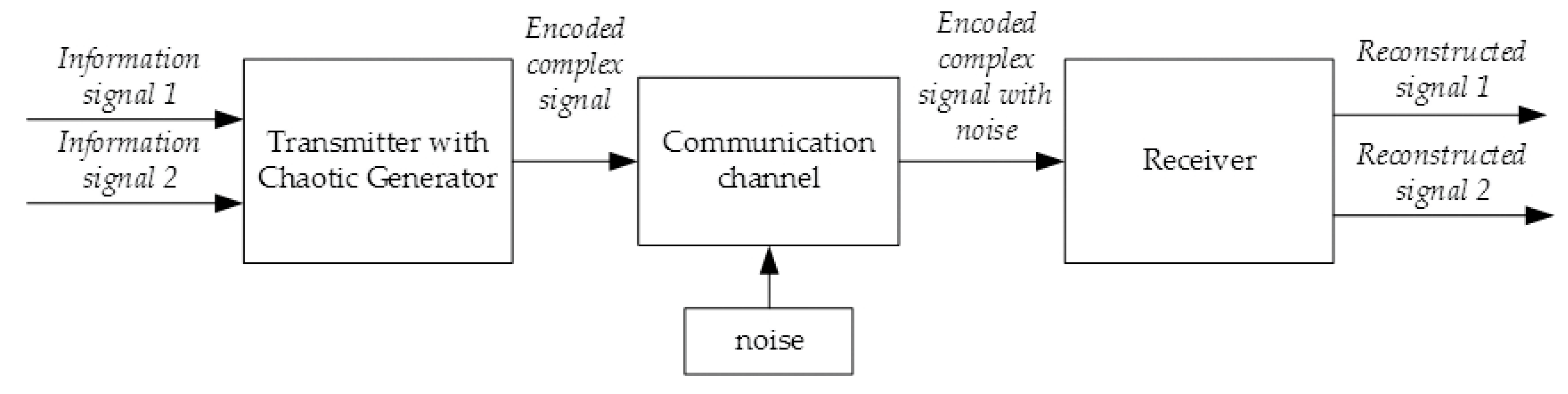
- We built a chaotic communication system viable structure based on the combination of chaotic generator nonlinear parametric modulation, method of global reconstruction of a dynamic system and nonlinear synergetic observer;
- Application of synergetic observer chaotic carrier communication system for image transmission.
2. Related Works and Methods Overview
- the structure of classical observers is rigid, i.e., the relationship between its variables are initially postulated but not formed during the design process for a particular object;
- the synergetic observer’s structure is formed directly during the design procedure, so the observer has to be specially designed for particular object model, but the design procedure is more complicated and should be defined in every case;
- the synergetic observer’s designed structure includes the right-hand sides of the equations of the chaotic generator, so it allows taking into account all the properties of a chaotic generator and the relationship between its variables.
3. Methodology and the System Design Procedure
3.1. General Methodology
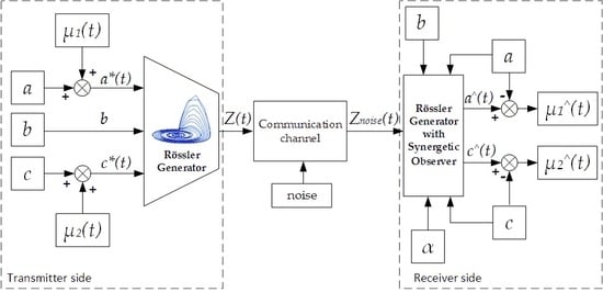
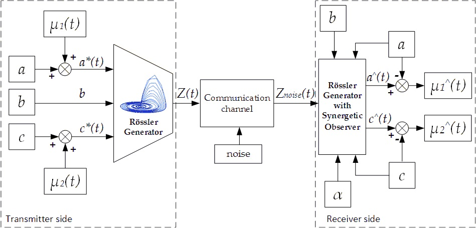
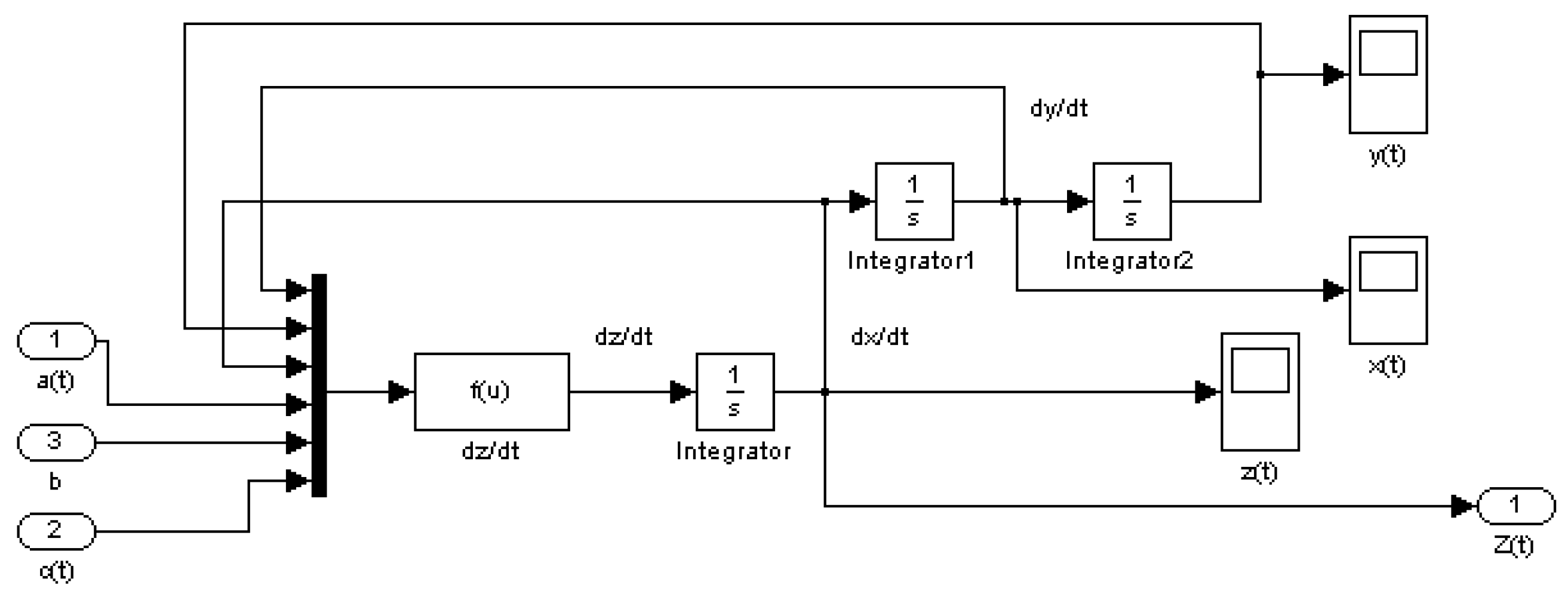
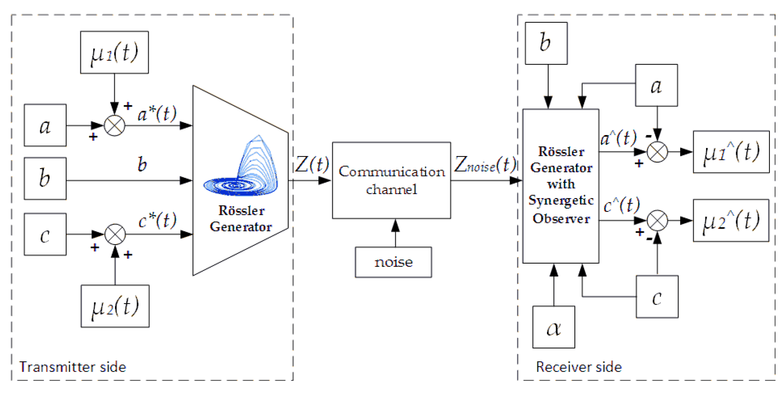
3.2. Chaotic Generator Mathematical Model and Two-Channel Chaotic Transmitter Block Diagramm
3.3. Security Analysis of Chaotic Carrier Data Transmission System with Parameters Nonlinear Modulation
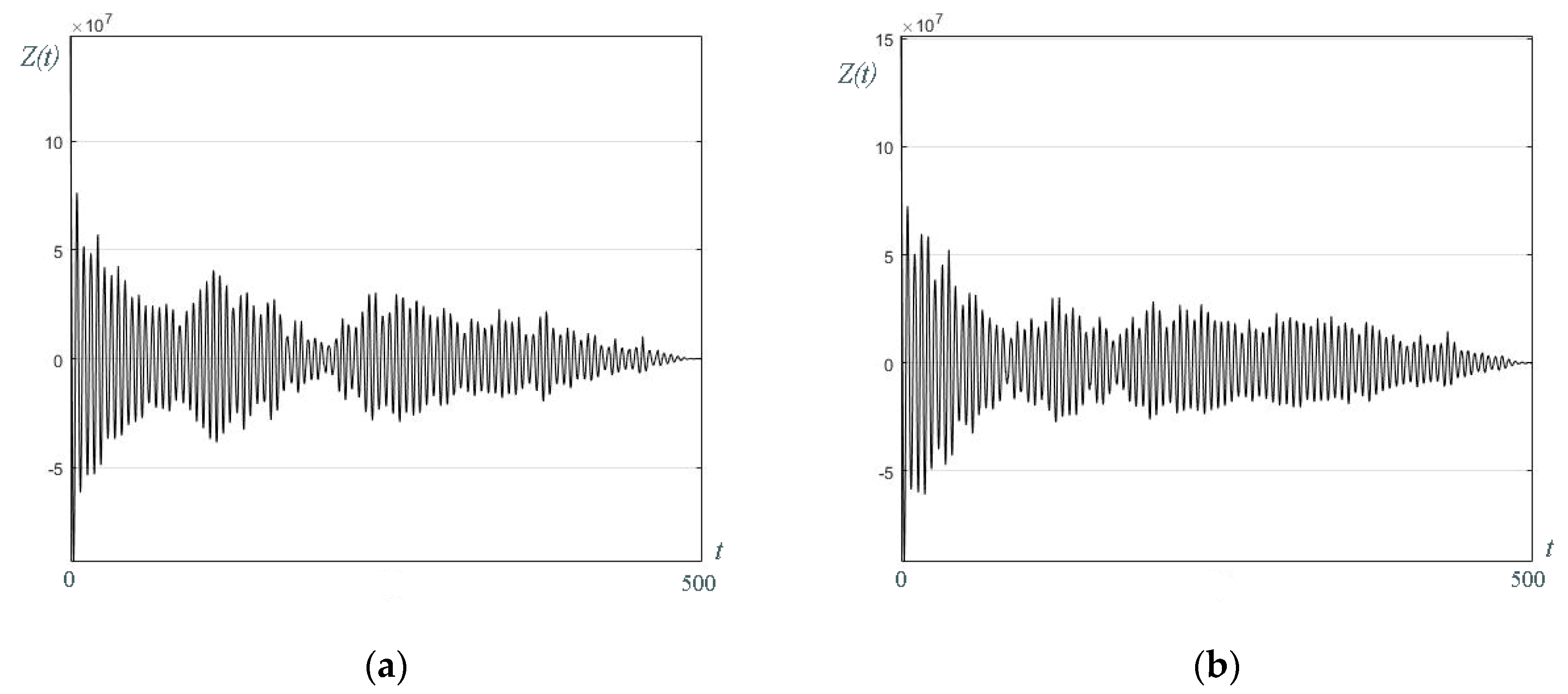
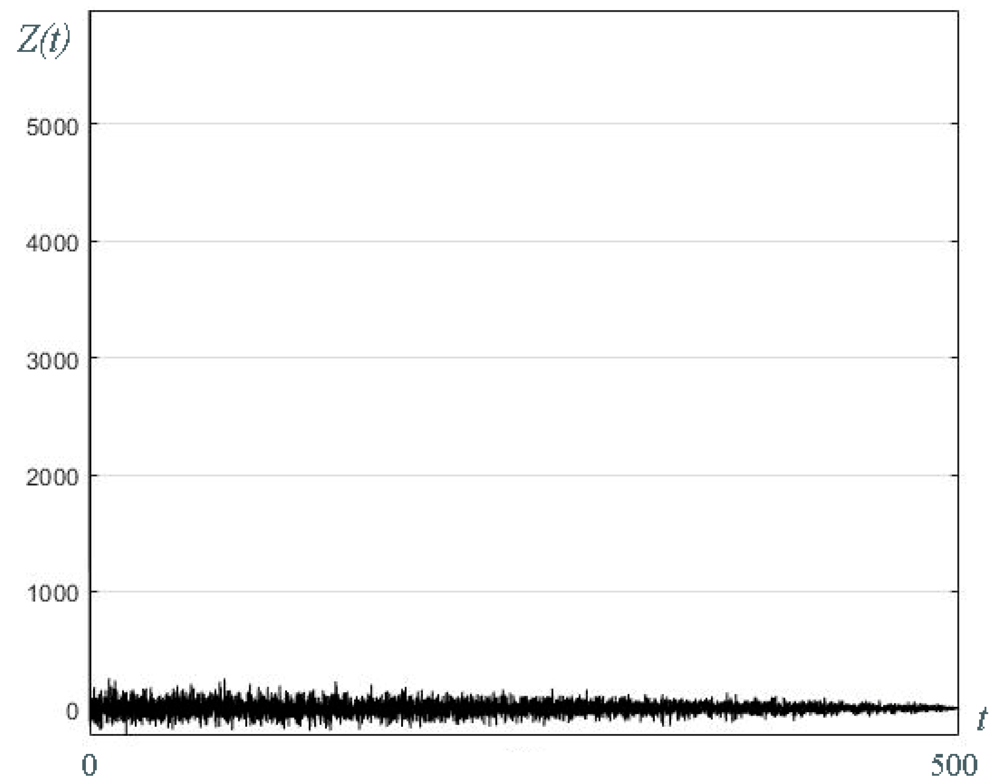
3.3.1. Autocorrelation Analysis
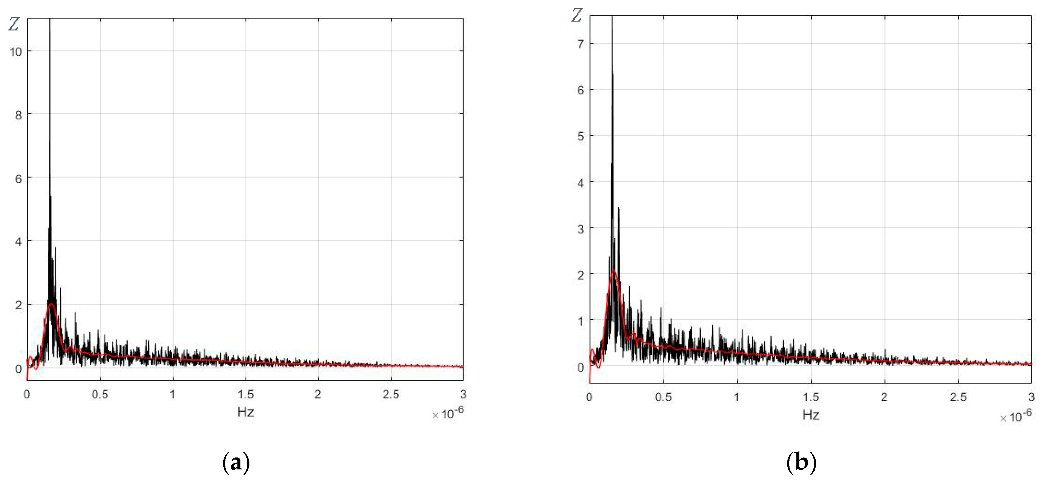
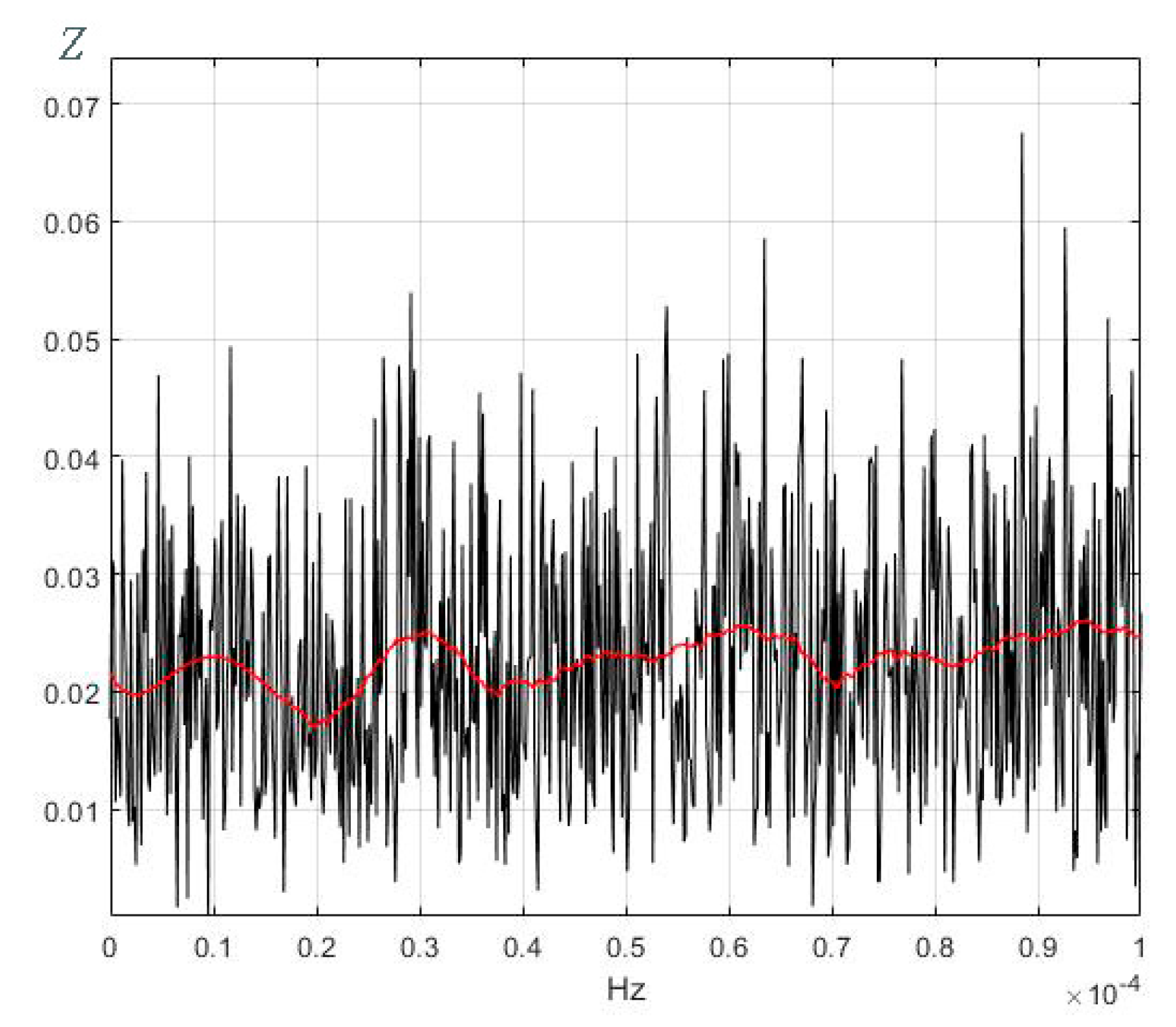
3.3.2. Fourier Series Analysis
3.4. Overall Steps of Synergetic Observer Design Procedure
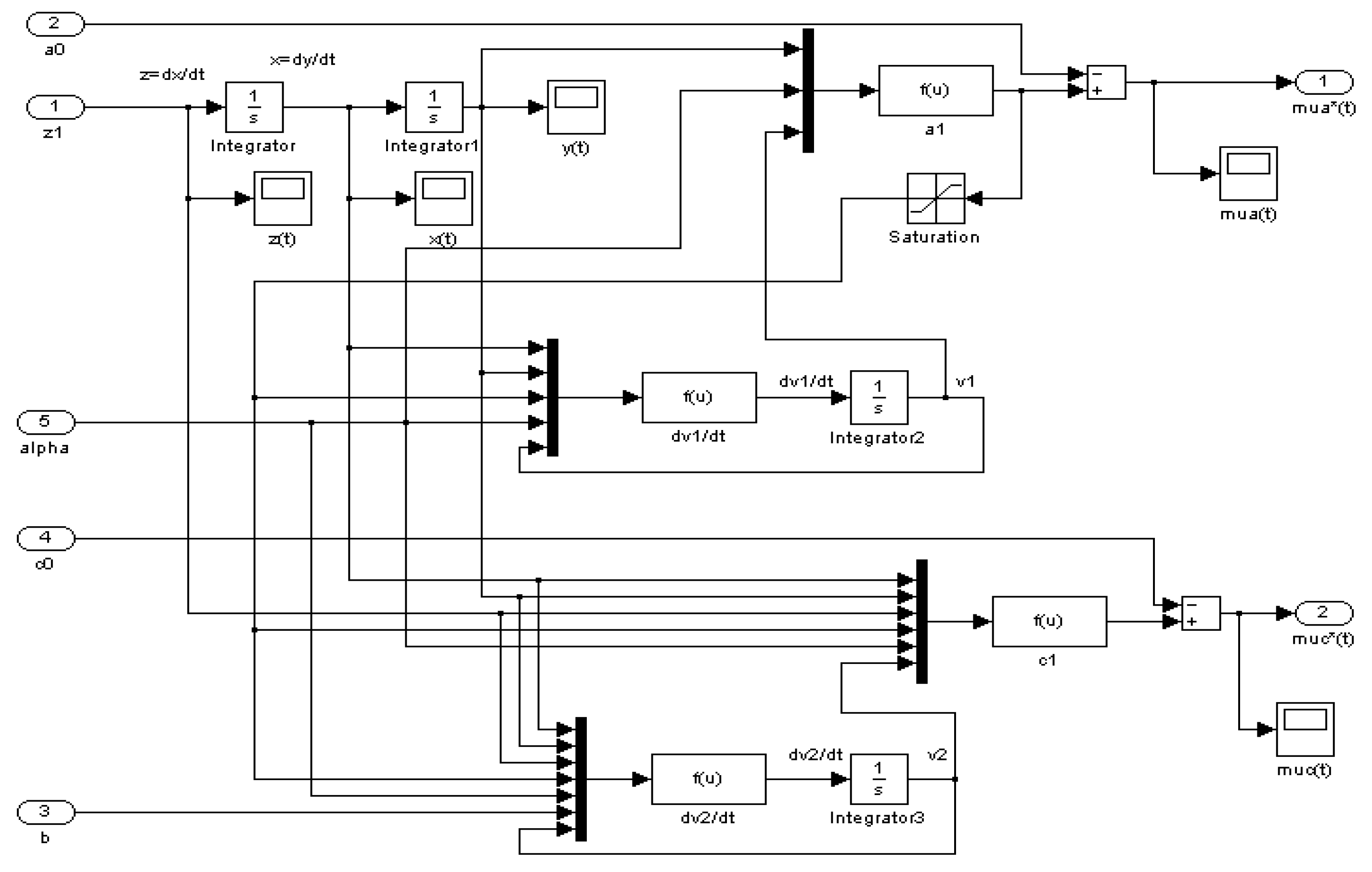
3.5. Two-Channel Synergetic Observer Analytical Design Procedure and Two-Channel Receiver Block Diagramm
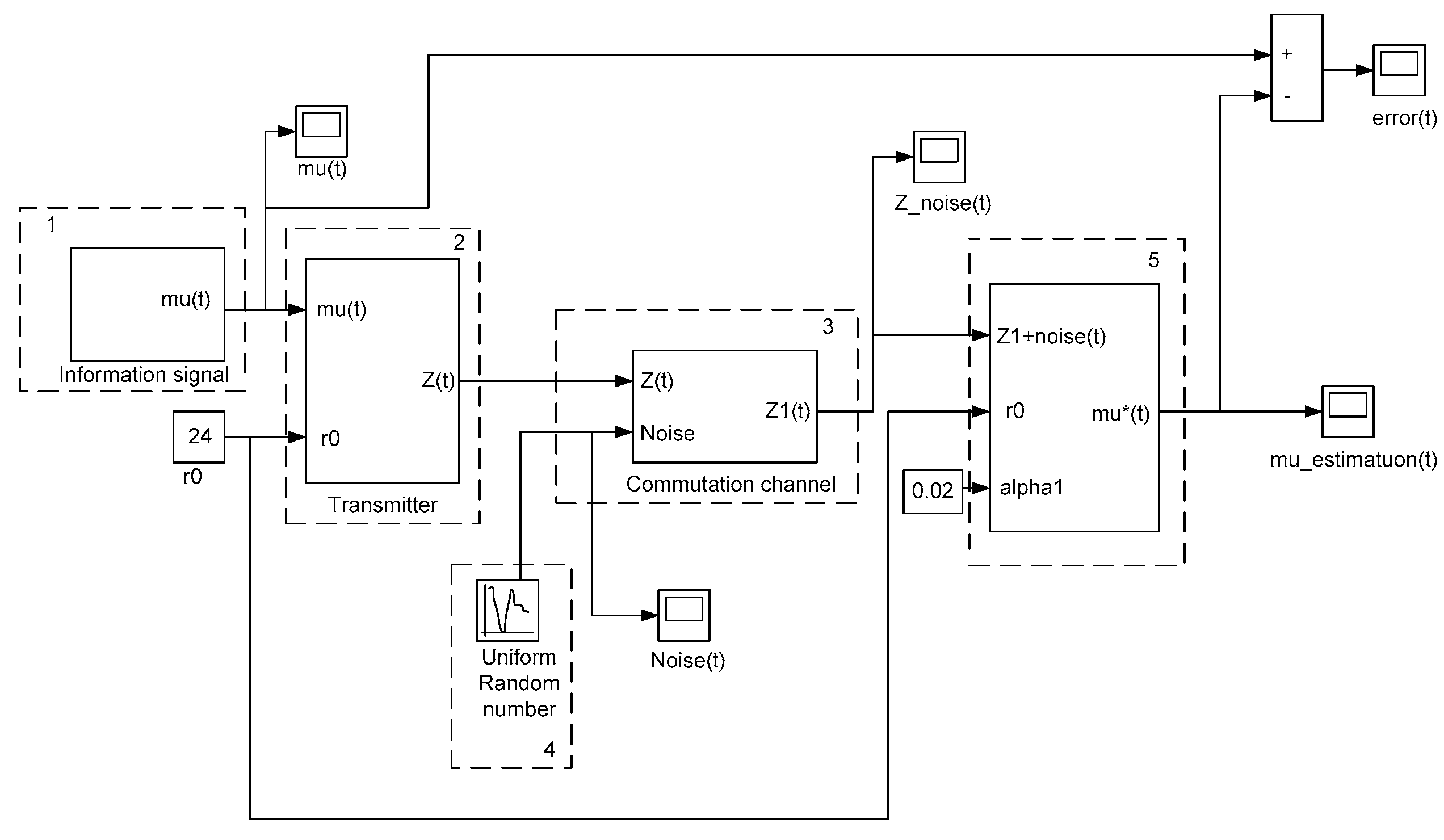
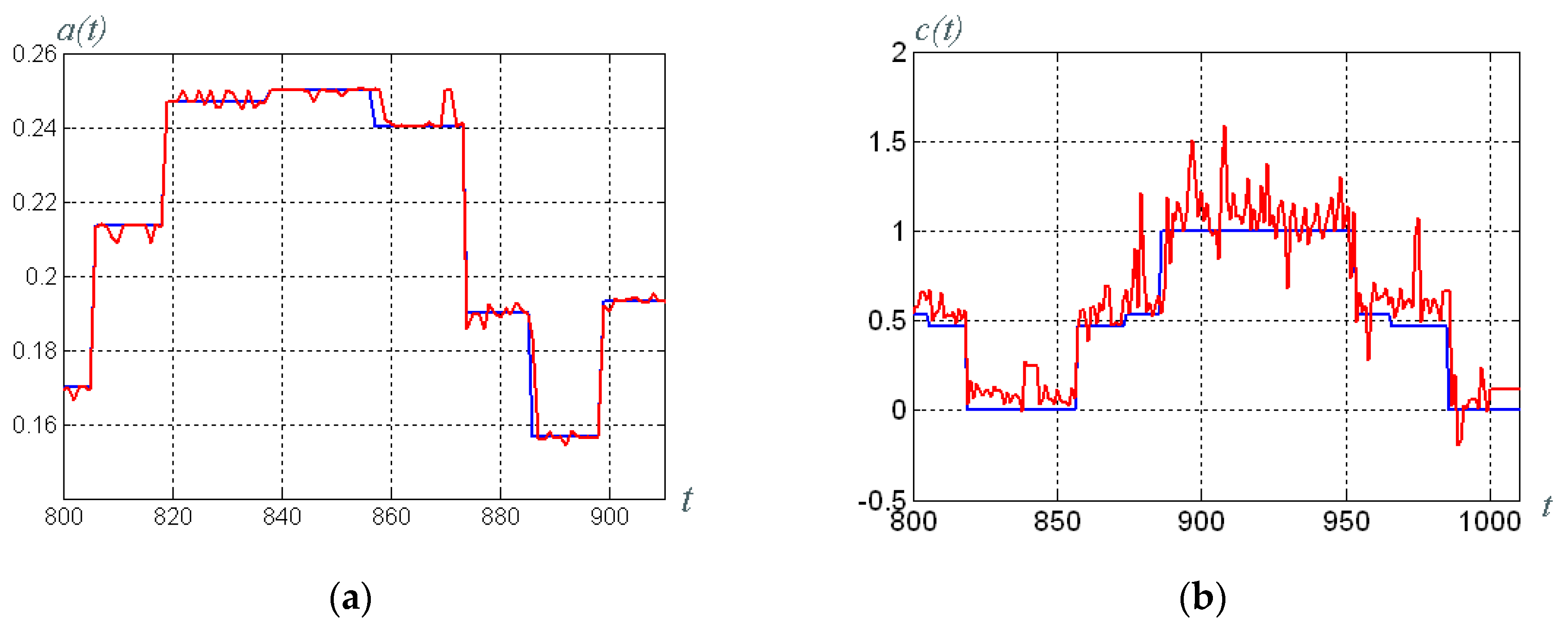
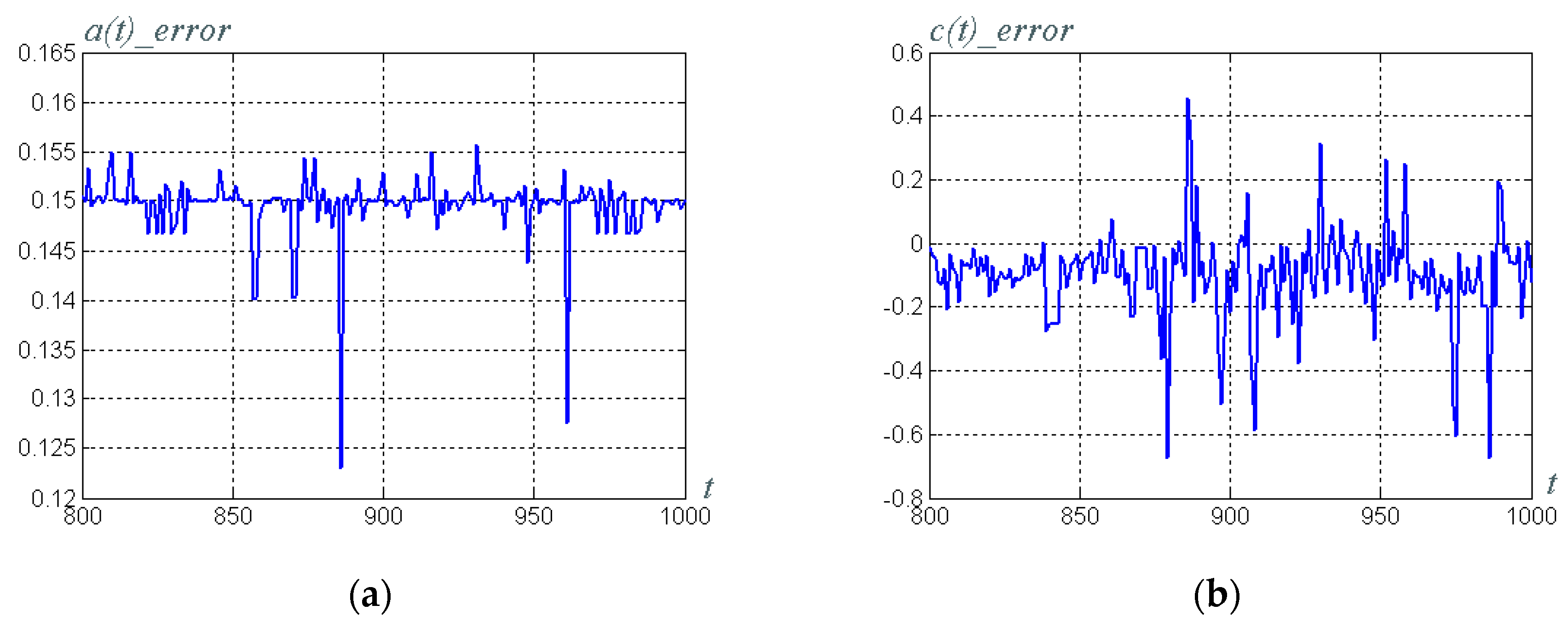
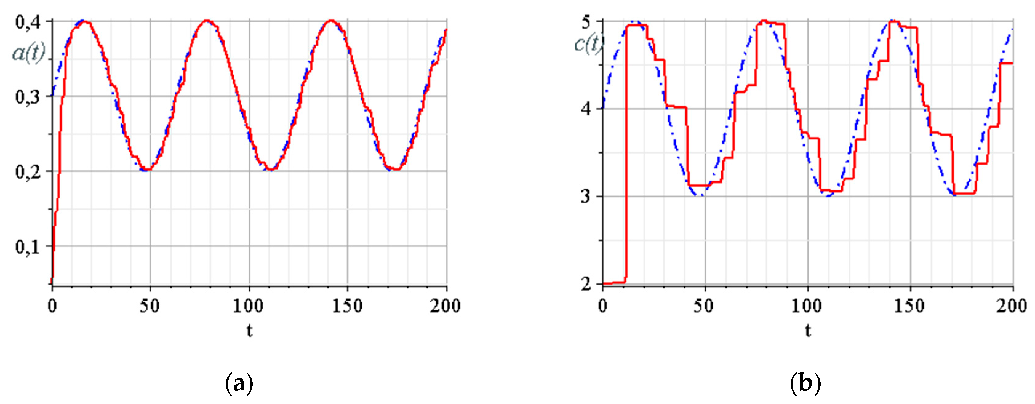
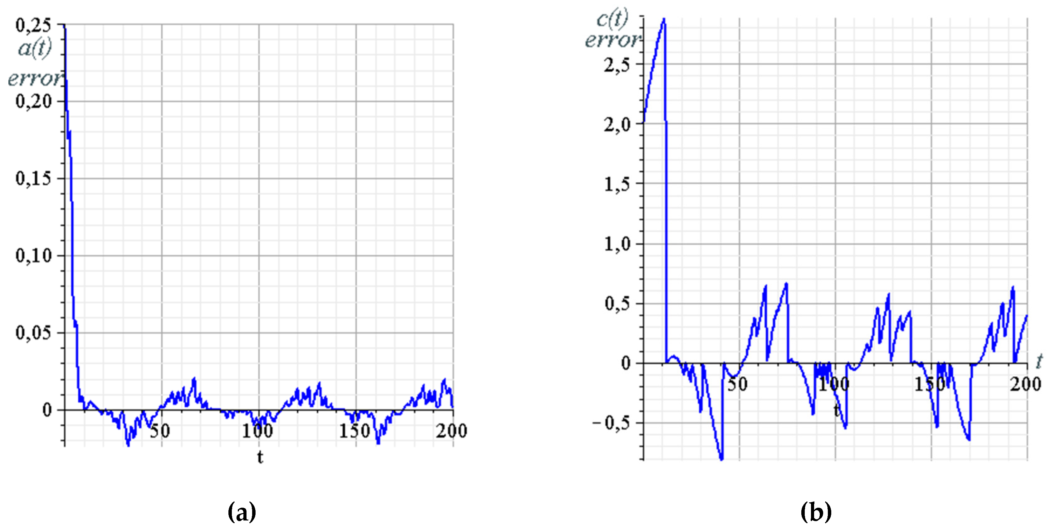
3.6. Building of the Data Trasmission System Model and Overall System Computer Simulation
- Rössler system parameter ; and
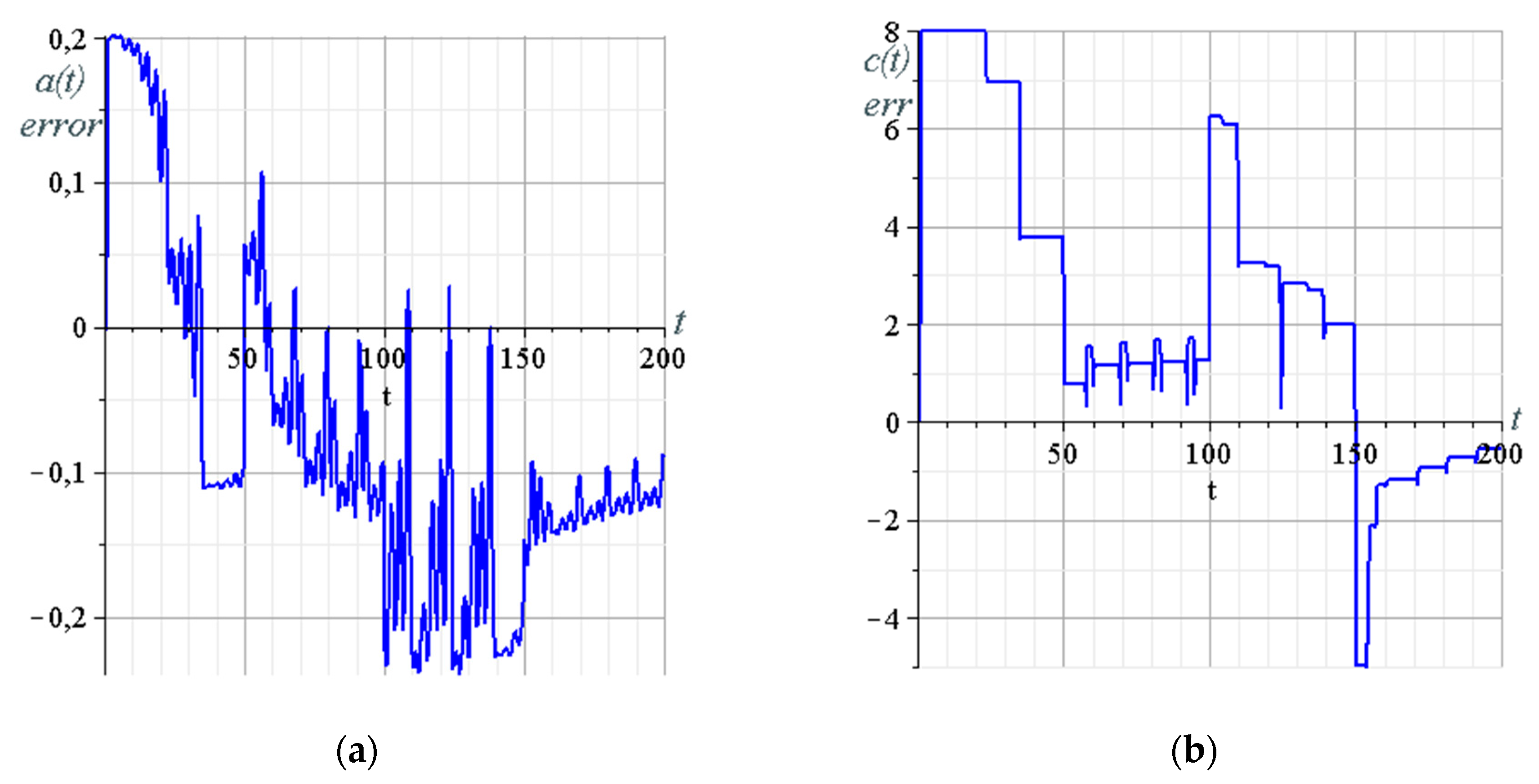
- the parameter of the synergetic observer, which determines the rate of estimation .
3.7. Alternative Reconstruction Method Demonstration
4. The System Hardware and Software Implementation Options
4.1. Brief Overview of System Hardware Implementation Issues
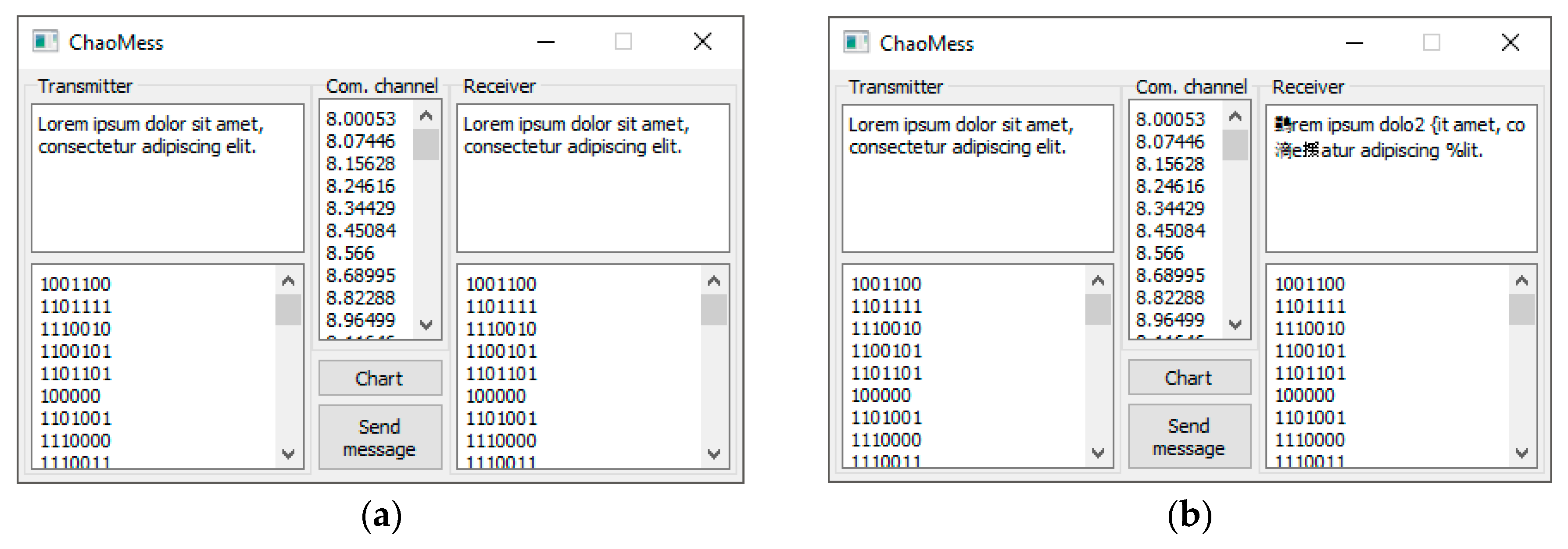
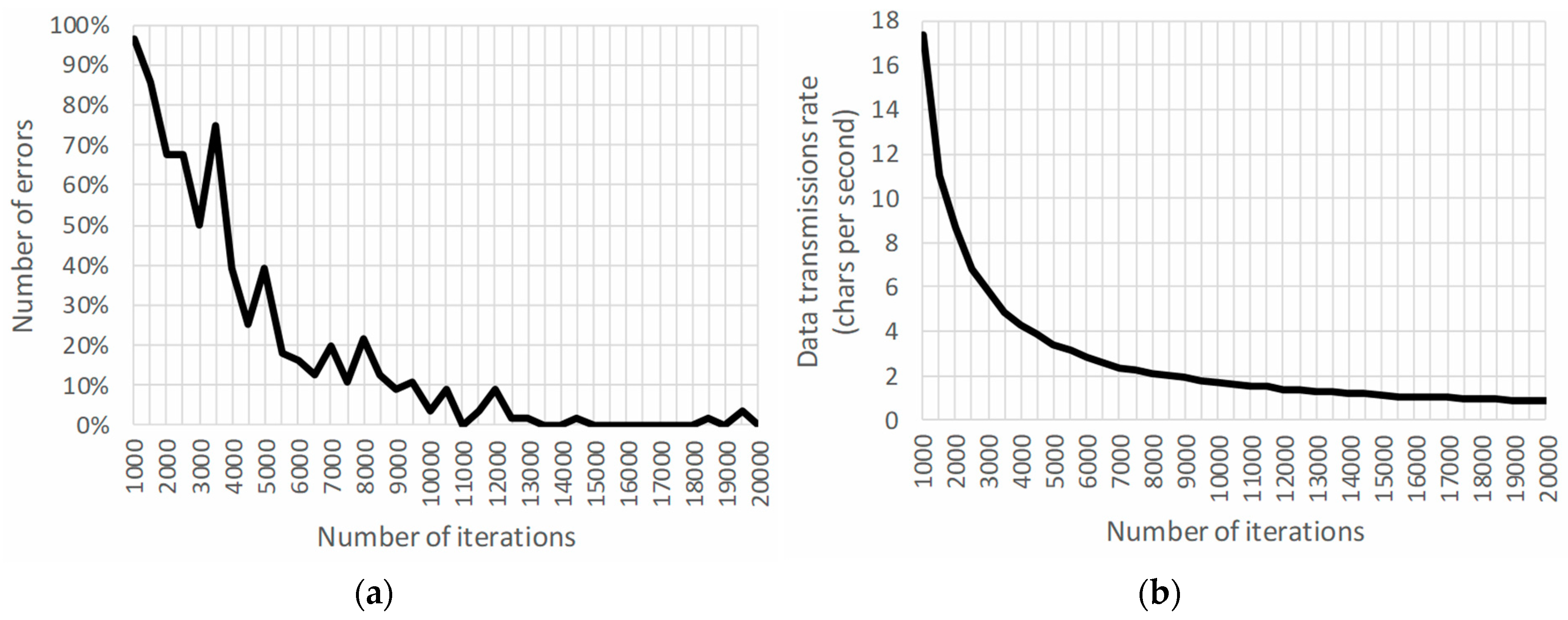
4.2. Example of Software Implementation on a Standard PC without MATLAB Computational Engine
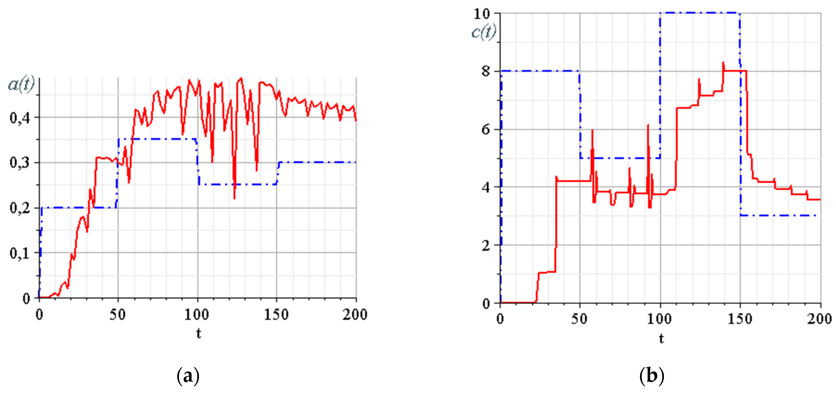
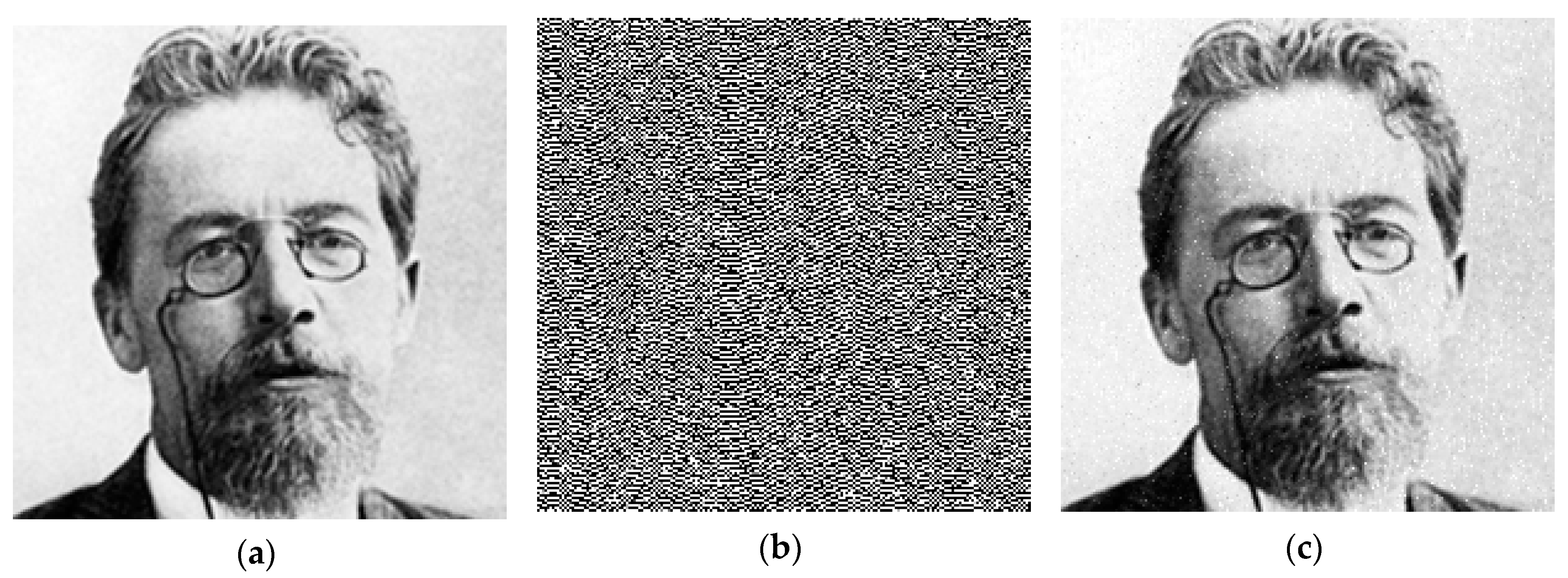
4.3. Example of Black-and-White Image Transmission with MATLAB Computational Engine
- fixed parameters of the Rössler system: ;
- the parameter of the synergetic observer that determines the rate of estimation of the parameter, ; and
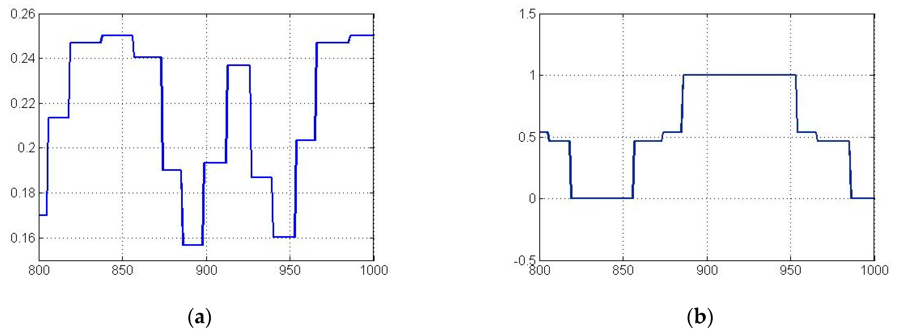
- the modulating signal is presented in the form of a stepwise time dependence, the height of each step corresponding to the gray level of the black-and-white image.
5. Discussion
6. Conclusions
Author Contributions
Funding
Conflicts of Interest
References
- Lorenz, E.N. Deterministic nonperiodic flow. J. Atmos. Sci. 1963, 20, 130–141. [Google Scholar] [CrossRef]
- Lorenz, E.N. Can chaos and intransitivity lead to interannual variability? Tellus A Dyn. Meteorol. Oceanogr. 1990, 42, 378–389. [Google Scholar] [CrossRef]
- Boccaletti, S.; Kurths, J.; Osipov, G.V.; Valladares, D.; Zhou, C. The synchronization of chaotic systems. Phys. Rep. 2002, 366, 1–101. [Google Scholar] [CrossRef]
- Geneser, S.; Kirby, R.; Sachse, F.B. Sensitivity Analysis of Cardiac Electrophysiological Models Using Polynomial Chaos. IEEE Eng. Med. Biol. 2005, 4, 4042–4045. [Google Scholar]
- Wang, L.; Feng, G. Analysis of a Predator-Prey System Concerning Impulsive Effect. Int. Workshop Chaos-Fractals Theor. Appl. 2009, 93–97. [Google Scholar]
- Cui, H.; Song, X. Research on Electricity Price Forecasting Based on Chaos Theory. Int. Semin. Future Inf. Technol. Manag. Eng. 2008, 398–401. [Google Scholar]
- Kiel, L.D.; Elliott, E. Chaos Theory in the Social Sciences: Foundations and Applications; University of Michigan Press: Ann Arbor, MI, USA, 1996; p. 360. [Google Scholar] [CrossRef]
- Nakamura, Y.; Sekiguchi, A. The chaotic mobile robot. IEEE Trans. Robot. Autom. 2001, 17, 898–904. [Google Scholar] [CrossRef]
- Feki, M. An adaptive chaos synchronization scheme applied to secure communication. Chaos, Solitons Fractals 2003, 18, 141–148. [Google Scholar] [CrossRef]
- Murali, K.; Lakshmanan, M. Secure communication using a compound signal from generalized synchronizable chaotic systems. Phys. Lett. A 1998, 241, 303–310. [Google Scholar] [CrossRef]
- Zaher, A.; Abu-Rezq, A. On the design of chaos-based secure communication systems. Commun. Nonlinear Sci. Numer. Simul. 2011, 16, 3721–3737. [Google Scholar] [CrossRef]
- Dmitriev, A.S.; Panas, A.I. Dynamic Chaos. New Data Media for Communication Systems; PHISMATLIT: Moscow, Russia, 2002; 251p. (In Russian) [Google Scholar]
- Anishchenko, V.S.; Pavlov, A.N.; Yanson, N.B. Reconstruction of dynamic systems as applied to secure communications. Tech. Phys. 1998, 43, 1401–1407. [Google Scholar] [CrossRef]
- Tami, T.; Messaoudene, T.; Ferdjouni, A.; Benzineb, O. Chaos secure communication’ implementation in FPGA. In Proceedings of the 2018 International Conference on Applied Smart Systems (ICASS), Medea, Algeria, 24–25 November 2018; pp. 1–6. [Google Scholar]
- Gunay, E.; Altun, K. BER analysis and application in FPGA and FPAA based communication systems. In Proceedings of the 2017 International Artificial Intelligence and Data Processing Symposium (IDAP), Malatya, Turkey, 16–17 September 2017; pp. 1–5. [Google Scholar]
- Silva, P.H.O.; Nepomuceno, E.G.; Vitorino, A.; Martins, S.A.M. A visual chaotic system simulation in Arduino platform controlled by Android app. In Proceedings of the 2017 IEEE World Engineering Education Conference (EDUNINE), Santos, Brazil, 19–22 March 2017; pp. 62–66. [Google Scholar]
- Voliansky, R.; Sadovoi, O.; Shramko, Y.; Volianska, N.; Sinkevych, O. Arduino-based Implementation of the Dual-channel Chaotic Generator. In Proceedings of the 2019 3rd International Conference on Advanced Information and Communications Technologies (AICT), Lviv, Ukraine, 2–6 July 2019; pp. 278–281. [Google Scholar]
- Zhuang, L.; Cao, L.; Wu, Y.; Zhong, Y.; Zhangzhong, L.; Zheng, W.; Wang, L. Parameter Estimation of Lorenz Chaotic System Based on a Hybrid Jaya-Powell Algorithm. IEEE Access 2020, 8, 20514–20522. [Google Scholar] [CrossRef]
- Guillén-Fernández, O.; Meléndez-Cano, A.; Tlelo-Cuautle, E.; Núñez-Pérez, J.C.; Rangel-Magdaleno, J. On the synchronization techniques of chaotic oscillators and their FPGA-based implementation for secure image transmission. PLoS ONE 2019, 14, e0209618. [Google Scholar] [CrossRef] [PubMed]
- Tlelo-Cuautle, E.; Rangel-Magdaleno, J.; Pano-Azucena, A.; Obeso-Rodelo, P.; Nuñez-Perez, J.-C. FPGA realization of multi-scroll chaotic oscillators. Commun. Nonlinear Sci. Numer. Simul. 2015, 27, 66–80. [Google Scholar] [CrossRef]
- Riaz, A.; Ali, M. Chaotic Communications, their applications and advantages over traditional methods of communication. In Proceedings of the 2008 6th International Symposium on Communication Systems, Networks and Digital Signal Processing, Graz, Austria, 25 July 2008; pp. 21–24. [Google Scholar]
- Short, K.M. Unmasking a modulated chaotic communications scheme. Int. J. Bifurc. Chaos 1996, 6, 367–375. [Google Scholar] [CrossRef]
- Yang, H.; Tang, W.K.; Chen, G.; Jiang, G.-P. System Design and Performance Analysis of Orthogonal Multi-Level Differential Chaos Shift Keying Modulation Scheme. IEEE Trans. Circuits Syst. I Regul. Pap. 2016, 63, 146–156. [Google Scholar] [CrossRef]
- Cheng, G.; Xu, W.; Chen, C.; Wang, L. SWIPT Schemes for Carrier Index Differential Chaos Shift Keying Modulation: A New Look at the Inactive Carriers. IEEE Trans. Veh. Technol. 2019, 68, 2557–2570. [Google Scholar] [CrossRef]
- Wang, S.F. Dynamical Analysis of Memristive Unified Chaotic System and Its Application in Secure Communication. IEEE Access 2018, 6, 66055–66061. [Google Scholar] [CrossRef]
- Isaeva, O.B.; Jalnine, A.Y.; Kuznetsov, S.P. Chaotic communication with robust hyperbolic transmitter and receiver. In Proceedings of the 2017 Progress in Electromagnetics Research Symposium-Spring (PIERS), St. Petersburg, Russia, 22–25 May 2017; pp. 3129–3136. [Google Scholar]
- Andrievsky, B.; Fradkov, A.L. Adaptive-based methods for information transmission by means of chaotic signal source modulation. Autom. Remote. Control. 2011, 72, 1967–1980. [Google Scholar] [CrossRef]
- Andrievsky, B. Information transmission based on adaptive synchronization of chaotic Lorenz systems over the digital communication channel. Cybern. Phys. 2013, 2, 10–14. [Google Scholar]
- Fradkov, A.L.; Pogromsky, A.Y. Introduction to Control of Oscillations and Chaos; World Scientific Pub. Co.: Singapore, 1998; 391p. [Google Scholar]
- Tyukin, I.Y.; Prokhorov, D.V.; Van Leeuwen, C. Adaptation and Parameter Estimation in Systems with Unstable Target Dynamics and Nonlinear Parametrization. IEEE Trans. Autom. Control. 2007, 52, 1543–1559. [Google Scholar] [CrossRef]
- Chien, T.-H.; Chen, Y.-C. Combination of Observer/Kalman Filter Identification and Digital Redesign of Observer-Based Tracker for Stochastic Chaotic Systems. In Proceedings of the 2016 International Symposium on Computer, Consumer and Control (IS3C), Xi’an, China, 4–6 July 2016; pp. 103–107. [Google Scholar]
- Wei, W.; Guo, L. Chaos control in AFM via disturbance observer based control. In Proceedings of the 2016 35th Chinese Control Conference (CCC), Chengdu, China, 27–29 July 2016; pp. 869–872. [Google Scholar]
- Zhang, J.; Zhu, F. Chaos synchronization and chaos-based secure communication based on new unknown input observer approach. In Proceedings of the 2016 35th Chinese Control Conference (CCC), Chengdu, China, 27–29 July 2016; pp. 1891–1896. [Google Scholar]
- Xiao, X.-S.; Pan, C. Observer-based adaptive synchronization of uncertain time-delay chaotic systems. In Proceedings of the 2017 36th Chinese Control Conference (CCC), Dalian, China, 26–28 July 2017; pp. 3321–3324. [Google Scholar]
- Datcu, O.; Stanciu, M.; Udrea, R.M. Secret speech transmission using a high order sliding mode observer. In Proceedings of the 2017 40th International Conference on Telecommunications and Signal Processing (TSP), Barcelona, Spain, 5–7 July 2017; pp. 161–164. [Google Scholar]
- Moysis, L.; Volos, C.; Pham, V.-T.; Goudos, S.; Stouboulos, I.; Gupta, M.K. Synchronization of a Chaotic System with Line Equilibrium using a Descriptor Observer for Secure Communication. In Proceedings of the 2019 8th International Conference on Modern Circuits and Systems Technologies (MOCAST), Thessaloniki, Greece, 13–15 May 2019; pp. 1–4. [Google Scholar]
- Gupta, M.; Tomar, N.K.; Mishra, V.K.; Bhaumik, S. Observer Design for Semilinear Descriptor Systems with Applications to Chaos-Based Secure Communication. Int. J. Appl. Comput. Math. 2017, 3, 1313–1324. [Google Scholar] [CrossRef]
- Kolesnikov, A.A. Introduction of synergetic control. In Proceedings of the 2014 American Control Conference, Portland, OR, USA, 4–6 June 2014; pp. 3013–3016. [Google Scholar]
- Kolesnikov, A.A.; Veselov, G.E.; Kolesnikova, S.I.; Kolesnikov, A.A.; Dzuba, J.N. Synergetic-cybernetic approach to creation of chaos-dynamics systems of data processing. Inf. Technol. Mag. 2013, 10, 1–32. (In Russian) [Google Scholar]
- Kolesnikov, A.A. Synergatic Methods of Control of Complex Systems: Theory of System Synthesis, 3rd ed.; URSS: Moscow, Russia, 2019; 240p, ISBN 978-5-397-06702-7. (In Russian) [Google Scholar]
- Kolesnikov, A.A. Analiticheskij sintez nelinejnyh sistem, optimal’nyh otnositel’no linejnyh agregirovannyh peremennyh. Elektromehanika 1985, 11, 71–79. [Google Scholar]
- Mushenko, A.; Dzuba, J.N.; Zolkin, A.D. Recovering of useful signal in chaotic carrier data transmission system with state observer. In Proceedings of the 2018 Moscow Workshop on Electronic and Networking Technologies (MWENT), Moscow, Russia, 14–16 March 2018; pp. 1–5. [Google Scholar]
- Kolesnikov, A.A.; Mushenko, A.; Dzuba, J.N.; Zolkin, A.D. Synergetic observer of state variables in problems of reconstruction of systems with chaotic dynamics. In Proceedings of the 2017 IEEE II International Conference on Control in Technical Systems (CTS), St. Petersburg, Russia, 25–27 October 2017; pp. 55–58. [Google Scholar]
- Rossler, O. An equation for continuous chaos. Phys. Lett. A 1976, 57, 397–398. [Google Scholar] [CrossRef]
- Flajolet, P.; Sedgewick, R. Analytic Combinatorics by Philippe Flajolet; Cambridge University Press (CUP): Cambridge, UK, 2009; p. 826. ISBN 978-0-521-89806-5. [Google Scholar]
- Smaoui, N.; Karouma, A.; Zribi, M.A. Secure communications based on the synchronization of the hyperchaotic Chen and the unified chaotic systems. Commun. Nonlinear Sci. Numer. Simul. 2011, 16, 3279–3293. [Google Scholar] [CrossRef]


| Reconstruction technique | Two Channel Estimation | Lyapunov Function Definition | Application to Nonlinear Objects | Observer structure | Need to Find a Control Law |
|---|---|---|---|---|---|
| Luenberger observer [32] | No | Not needed | Limited | Rigid/Postulated | Yes |
| Kalman filter [31] | No | Not needed | Limited | Rigid/Postulated | Yes |
| Chaotic synchronization [25,27] | No | Required | Yes | Rigid/Postulated | Yes |
| Adaptive observer [27,28,29] | No | Not needed | Yes | Rigid/Postulated | No |
| SMC observer [35] | No | Not needed | Yes | Rigid/Postulated | Yes |
| Reduced order observer [36,37] | No | Required | Yes | Rigid/Postulated | No |
| Synergetic observer [39] | Yes | Not needed | Yes | Object-defined | No |
| Design Step | Description |
|---|---|
| Step 1 | Deduce the system into a form suitable for transmitting a signal over a communication channel: for the initial nonlinear system of the 3rd order, using the global reconstruction of a dynamic system [13] replace the variables for transmitting a useful signal to the communication channel (Equation (3)). |
| Step 2 | Perform multiplicative parametric modulation: select two constant coefficients in different equations of the original model and replace them with the sum of this coefficient and the time function that reflects the useful signal (for each of the coefficients) (System (5)). |
| Step 3 | Adopt these sums as new unknown parameters and and extend the generator’s initial model by dynamic models of these parameters , . As a result we get a 5th order system with 3 observable (x, y and z) and 2 unobservable ( and ) variables (Equation (9)). |
| Step 4 | Introduce variables and , which will be estimates of the parameters and . |
| Step 5 | To find them we define the vector of the macro variable and write down the reduction equations with new unknown functions that will be defined on the final steps of the procedure (Matrix (10)). |
| Step 6 | Differentiating reduction equations with respect to time (System (12)). |
| Step 7 | Write down a main functional equation of the ADAR method [38,40] that will define the final system desired dynamics. The L coefficients matrix will provide a desired system stability condition (Equation (13)). |
| Step 8 | From the main functional equation with respect to the extended initial mathematical model, the vector of the macro variable, the reduction equations and its derivative we obtain the draft equations of the observer (Equation (14)). |
| Step 9 | The observer equations should not contain unobservable state variables, therefore, from the draft observer equations it is necessary to write out all terms containing unobservable variables and equate them to zero. We thus get a system of the 4th order (Equation (15)). |
| Step 10 | For the resulting system, we choose values of the coefficients L based on the stability condition of the observer and the main functional equation (Equations (16)–(18)). |
| Step 11 | We obtain the observer Equation (19) taking into account the found functions for the reduction Equation (11). |
© 2020 by the authors. Licensee MDPI, Basel, Switzerland. This article is an open access article distributed under the terms and conditions of the Creative Commons Attribution (CC BY) license (http://creativecommons.org/licenses/by/4.0/).
Share and Cite
Mushenko, A.; Dzuba, J.; Nekrasov, A.; Fidge, C. A Data Secured Communication System Design Procedure with a Chaotic Carrier and Synergetic Observer. Electronics 2020, 9, 497. https://doi.org/10.3390/electronics9030497
Mushenko A, Dzuba J, Nekrasov A, Fidge C. A Data Secured Communication System Design Procedure with a Chaotic Carrier and Synergetic Observer. Electronics. 2020; 9(3):497. https://doi.org/10.3390/electronics9030497
Chicago/Turabian StyleMushenko, Alexey, Julia Dzuba, Alexey Nekrasov, and Colin Fidge. 2020. "A Data Secured Communication System Design Procedure with a Chaotic Carrier and Synergetic Observer" Electronics 9, no. 3: 497. https://doi.org/10.3390/electronics9030497
APA StyleMushenko, A., Dzuba, J., Nekrasov, A., & Fidge, C. (2020). A Data Secured Communication System Design Procedure with a Chaotic Carrier and Synergetic Observer. Electronics, 9(3), 497. https://doi.org/10.3390/electronics9030497