Electromagnetic Field Based WPT Technologies for UAVs: A Comprehensive Survey

 ,
, 
 and
and
Abstract
1. Introduction
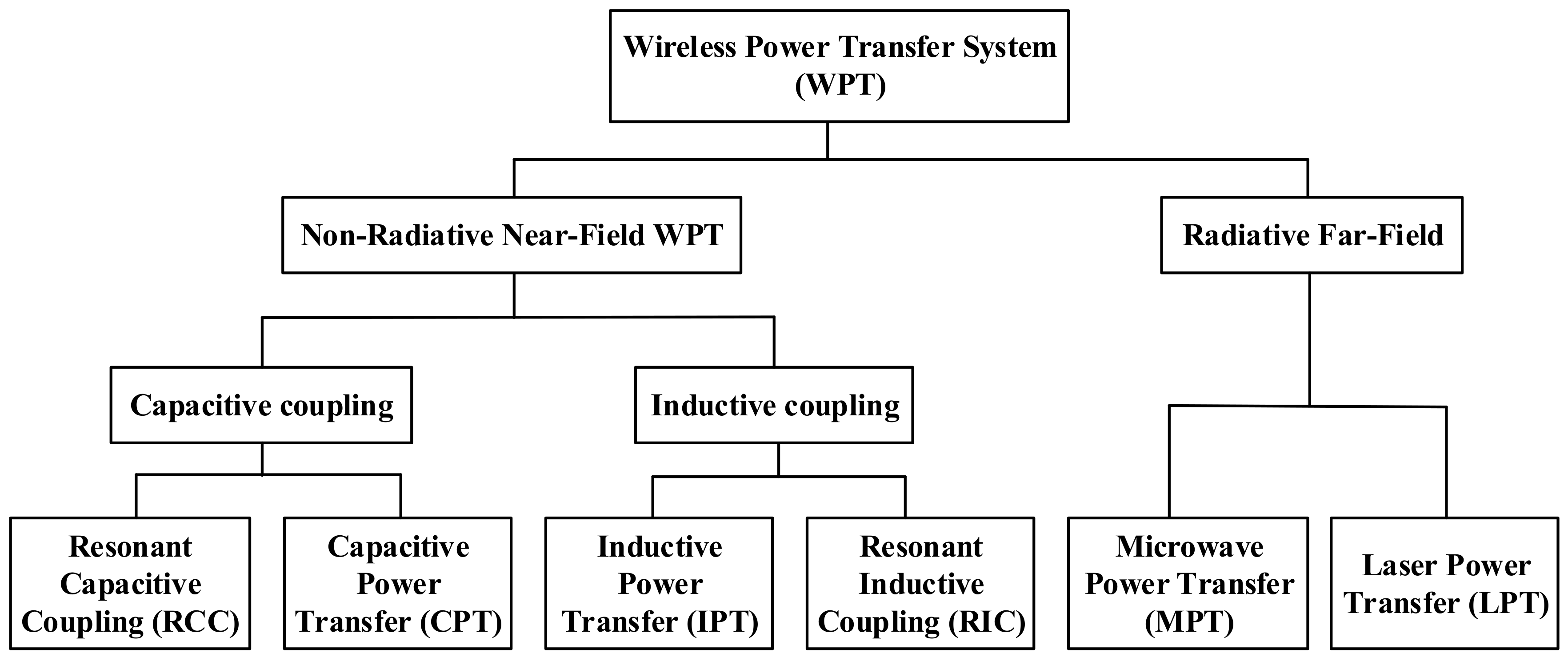
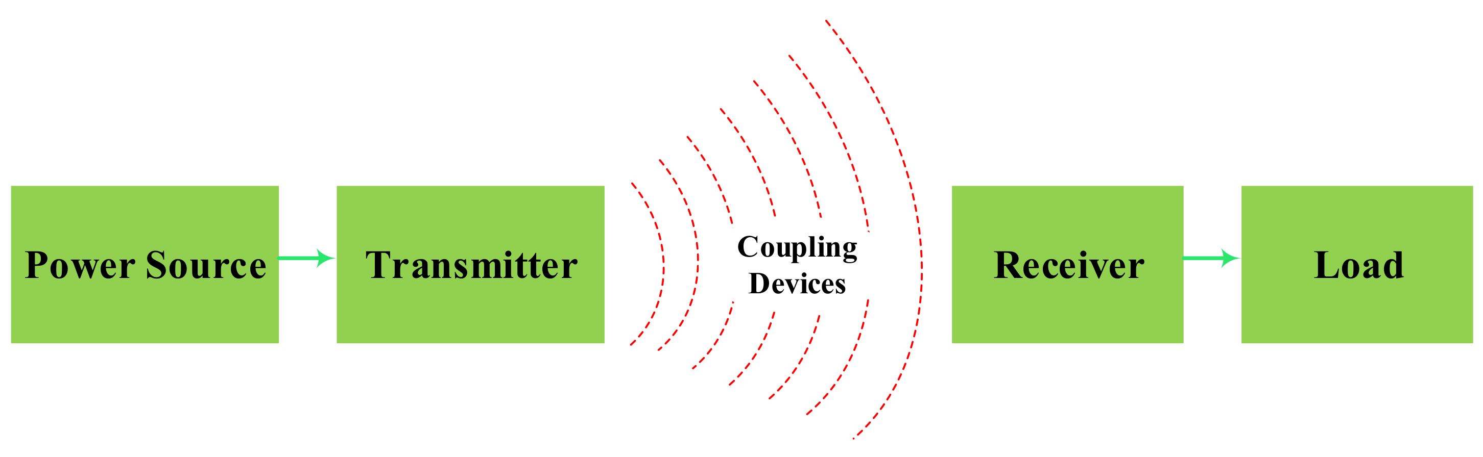
2. Wireless Power Transfer Technology Principle
2.1. Near-Field Wireless Power Transfer Techniques
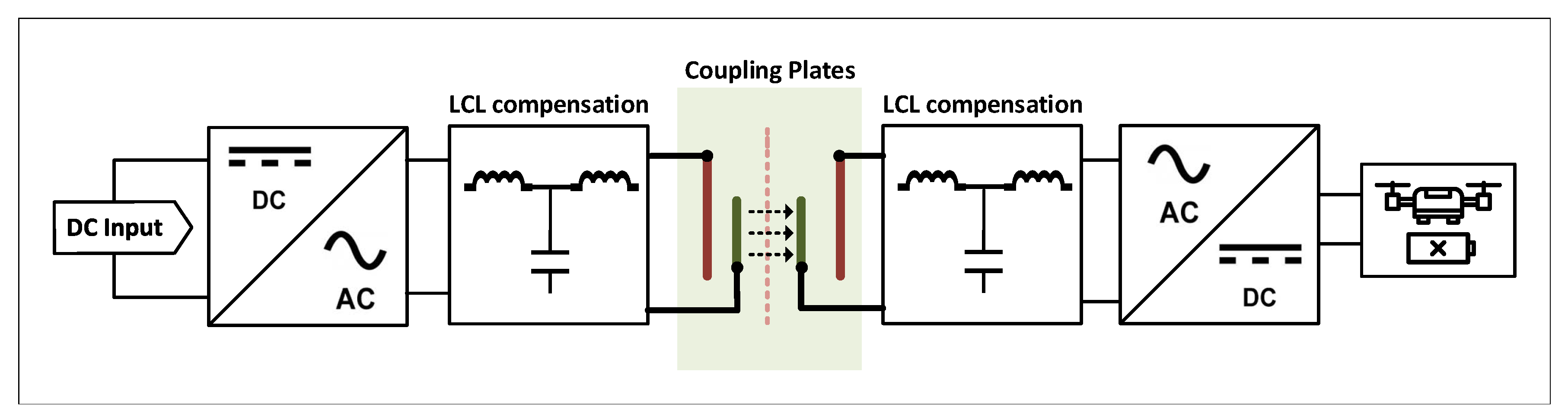
2.1.1. Capacitive Coupling Wireless Power Transfer
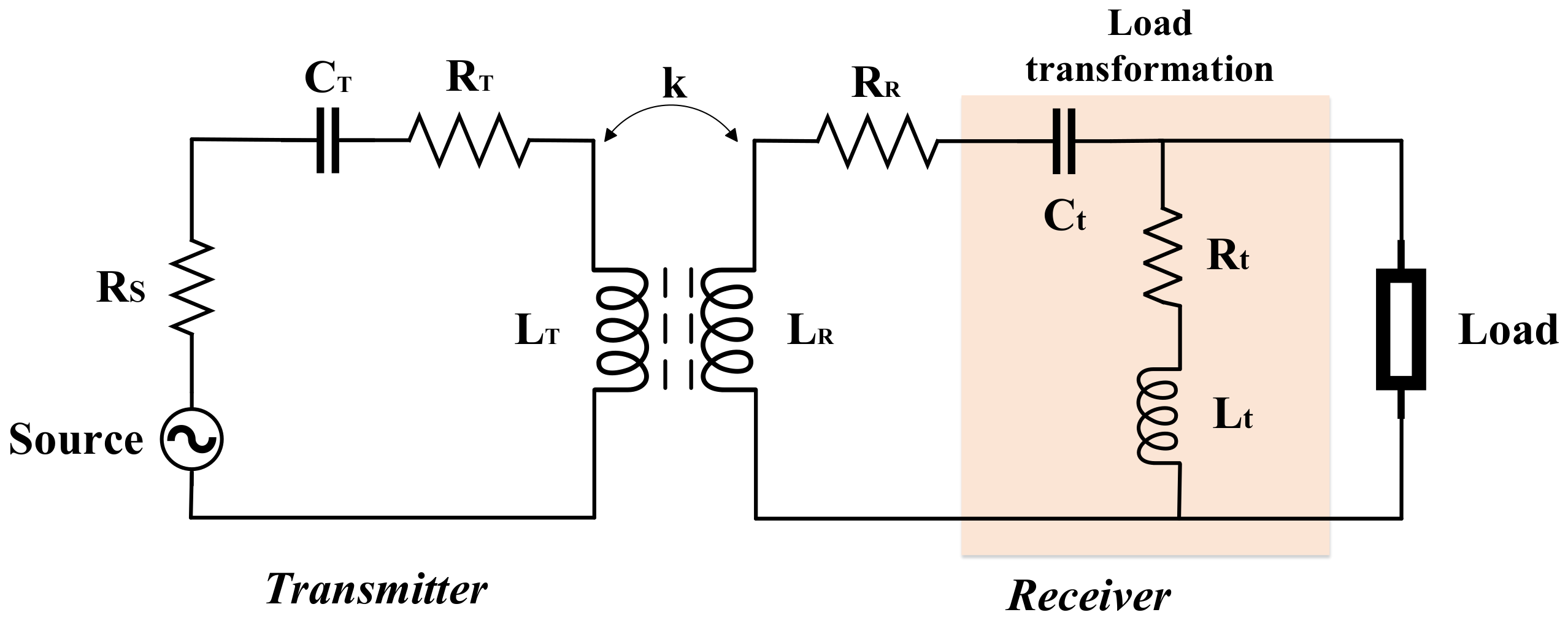
2.1.2. Inductive Coupling Wireless Power Transfer
- The resonant frequency is:where L and C are the inductance and the capacitance of the circuit, respectively.
- The quality factor, which describes the resonance behavior of an underdamped harmonic oscillator (resonator). To a high-quality quality factor corresponds a system with a high harmonic response quality. It is defined as [56]:where is the frequency in rad/s and R is the oscillator resistance.
- The coupling coefficient is defined as:where M is mutual inductance and and are the inductance of the transmitting and receiving coils, respectively.
- The figure of merit is a quantity used to characterize the performance of the device, system, or methods relative to the alternatives.where and are the quality factors of the transmitting and receiving coil, respectively.
2.2. Far-Field Wireless Power Transfer Techniques
3. Near-Field WPT Technologies
3.1. CCWPT Technologies
3.1.1. Operating Frequency
3.1.2. The Compensation
3.1.3. Boost up Circuits
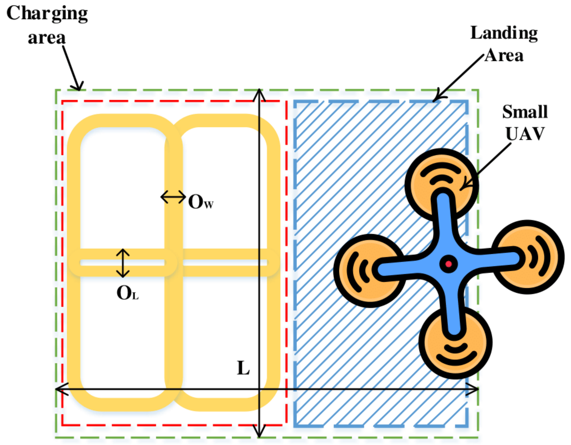
3.1.4. CCWPT: Deployed Systems
3.2. ICWPT Technologies
3.2.1. Inductive Power Transfer Methods
3.2.2. Resonant Inductive Coupling
3.2.3. Other Improvements
4. Far-Field WPT Technologies
4.1. Microwave Power Transfer
4.1.1. Antenna Design
4.1.2. Matching Network
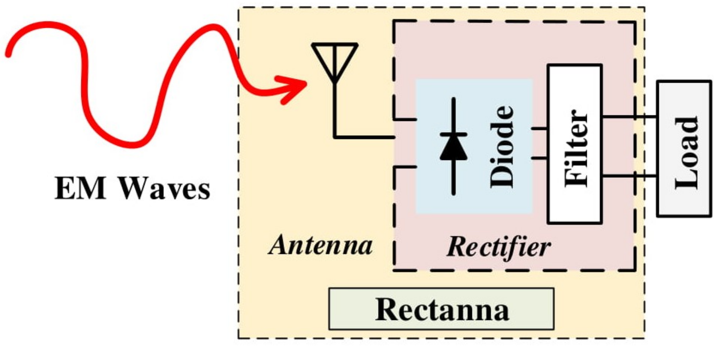
4.1.3. Rectifier
4.1.4. Deploying the System
4.2. Laser Power Transfer
5. Opportunities and Challenges of WPT for UAVs
5.1. Near-Field WPT
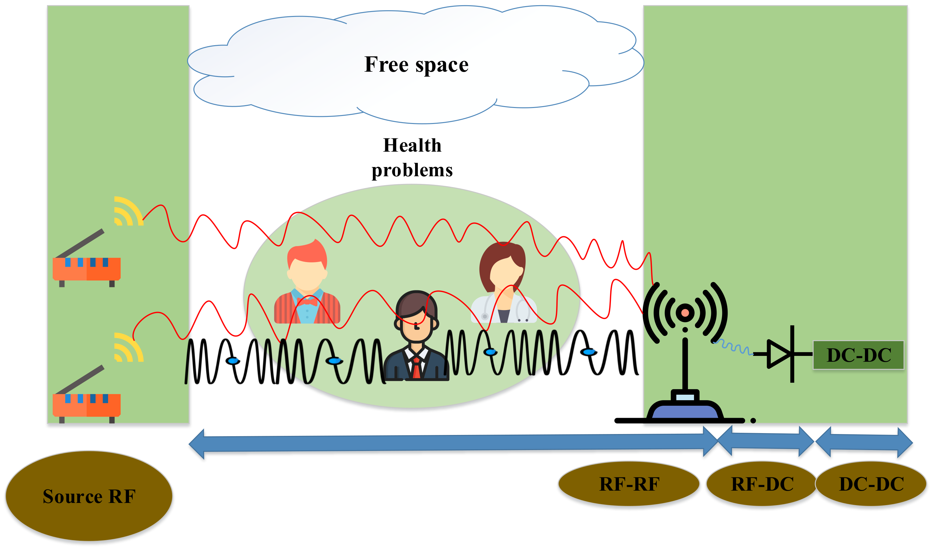
5.2. Far-Field WPT
6. Conclusions and Further Work
Author Contributions
Funding
Acknowledgments
Conflicts of Interest
References
- Lu, M.; Bagheri, M.; James, A.P.; Phung, T. Wireless Charging Techniques for UAVs: A Review, Reconceptualization, and Extension. IEEE Access 2018, 6, 29865–29884. [Google Scholar] [CrossRef]
- Nguyen, M.T.; Nguyen, T.H. Wireless Power Transfer: A Survey of Techniques, and Applications on Communication Networks. ICSES Trans. Comput. Netw. Commun. (ITCNC) 2018, 4, 1–5. [Google Scholar]
- Zeng, Y.; Zhang, R.; Lim, T.J. Wireless Communications with Unmanned Aerial Vehicles: Opportunities and Challenges. IEEE Commun. Mag. 2016, 54, 36–42. [Google Scholar] [CrossRef]
- Mozaffari, M.; Saad, W.; Bennis, M.; Debbah, M. Unmanned Aerial Vehicle With Underlaid Device-to-Device Communications: Performance and Tradeoffs. IEEE Trans. Wirel. Commun. 2016, 15, 3949–3963. [Google Scholar] [CrossRef]
- Lewis, P. CCTV in the sky: Police plan to use military-style spy drones. Guardian 2010, 23, 1. [Google Scholar]
- Public Intelligence. Drone Aircraft Are Patrolling US Cities. Public Intelligence, 26 April 2010; 1. [Google Scholar]
- Barnes, J.E. Military Refines a “Constant Stare against our Enemy”. Los Angeles Times, 2 November 2009; 1. [Google Scholar]
- d’Oliveira, F.A.; de Melo, F.C.L.; Devezas, T.C. High-altitude platforms—Present situation and technology trends. J. Aerosp. Technol. Manag. 2016, 8, 249–262. [Google Scholar] [CrossRef]
- Chandrasekharan, S.; Gomez, K.; Al-Hourani, A.; Kandeepan, S.; Rasheed, T.; Goratti, L.; Reynaud, L.; Grace, D.; Bucaille, I.; Wirth, T.; et al. Designing and implementing future aerial communication networks. IEEE Commun. Mag. 2016, 54, 26–34. [Google Scholar] [CrossRef]
- Silvagni, M.; Tonoli, A.; Zenerino, E.; Chiaberge, M. Multipurpose UAV for search and rescue operations in mountain avalanche events. Geomat. Nat. Hazards Risk 2017, 8, 18–33. [Google Scholar] [CrossRef]
- Niethammer, U.; James, M.; Rothmund, S.; Travelletti, J.; Joswig, M. UAV based remote sensing of the Super-Sauze landslide: Evaluation and results. Eng. Geol. 2012, 128, 2–11. [Google Scholar] [CrossRef]
- Hunt, E.R.; Hively, W.D.; Fujikawa, S.; Linden, D.; Daughtry, C.S.; McCarty, G. Acquisition of NIR-green-blue digital photographs from unmanned aircraft for crop monitoring. Remote Sens. 2010, 2, 290–305. [Google Scholar] [CrossRef]
- Honkavaara, E.; Saari, H.; Kaivosoja, J.; Pölönen, I.; Hakala, T.; Litkey, P.; Mäkynen, J.; Pesonen, L. Processing and assessment of spectrometric, stereoscopic imagery collected using a lightweight UAV spectral camera for precision agriculture. Remote Sens. 2013, 5, 5006–5039. [Google Scholar] [CrossRef]
- Hugenholtz, C.H.; Whitehead, K.; Brown, O.W.; Barchyn, T.E.; Moorman, B.J.; LeClair, A.; Riddell, K.; Hamilton, T. Geomorphological mapping with a small unmanned aircraft system (sUAS): Feature detection and accuracy assessment of a photogrammetrically-derived digital terrain model. Geomorphology 2013, 194, 16–24. [Google Scholar] [CrossRef]
- Whitehead, K.; Moorman, B.; Hugenholtz, C. Low-cost, on-demand aerial photogrammetry for glaciological measurement. Cryosphere Discuss. 2013, 7, 3043–3057. [Google Scholar] [CrossRef]
- Gheisari, M.; Irizarry, J.; Walker, B.N. UAS4SAFETY: The potential of unmanned aerial systems for construction safety applications. In Proceedings of the Construction Research Congress 2014: Construction in a Global Network, Atlanta, GA, USA, 19–21 May 2014; pp. 1801–1810. [Google Scholar]
- Sankarasrinivasan, S.; Balasubramanian, E.; Karthik, K.; Chandrasekar, U.; Gupta, R. Health monitoring of civil structures with integrated UAV and image processing system. Procedia Comput. Sci. 2015, 54, 508–515. [Google Scholar] [CrossRef]
- Mohamadi, F. Vertical Takeoff and Landing (VTOL) Small Unmanned Aerial System for Monitoring Oil and Gas Pipelines. U.S. Patent 8,880,241, 4 November 2014. [Google Scholar]
- Bretschneider, T.R.; Shetti, K. UAV based gas pipeline leak detection. In Proceedings of the ARCS 2015, Porto, Portugal, 24–27 March 2015. [Google Scholar]
- Muchiri, N.; Kimathi, S. A review of applications and potential applications of UAV. In Proceedings of the 2016 Sustainable Research and Innovation Conference, Nairobi, Kenya, 4–6 May 2016; pp. 280–283. [Google Scholar]
- Mathur, P.; Nielsen, R.H.; Prasad, N.R.; Prasad, R. Data collection using miniature aerial vehicles in wireless sensor networks. IET Wirel. Sens. Syst. 2016, 6, 17–25. [Google Scholar] [CrossRef]
- Khanal, S.; Fulton, J.; Shearer, S. An overview of current and potential applications of thermal remote sensing in precision agriculture. Comput. Electron. Agric. 2017, 139, 22–32. [Google Scholar] [CrossRef]
- Howell, C.T., III; Jones, F.; Thorson, T.; Grube, R.; Mellanson, C.; Joyce, L.; Coggin, J.; Kennedy, J. The First Government Sanctioned Delivery of Medical Supplies by Remotely Controlled Unmanned Aerial System (UAS). In Proceedings of the Xponential 2016, New Orleans, LA, USA, 2–5 May 2016. [Google Scholar]
- Lee, B.; Kwon, S.; Park, P.; Kim, K. Active power management system for an unmanned aerial vehicle powered by solar cells, a fuel cell, and batteries. IEEE Trans. Aerosp. Electron. Syst. 2014, 50, 3167–3177. [Google Scholar] [CrossRef]
- Campi, T.; Cruciani, S.; Feliziani, M. Wireless power transfer technology applied to an autonomous electric UAV with a small secondary coil. Energies 2018, 11, 352. [Google Scholar] [CrossRef]
- Nguyen, N.M.; Nguyen, L.D.; Duong, T.Q.; Tuan, H.D. Real-Time Optimal Resource Allocation for Embedded UAV Communication Systems. IEEE Wirel. Commun. Lett. 2019, 8, 225–228. [Google Scholar] [CrossRef]
- Nguyen, C.V.; Quyen, T.V.; Le, A.M.; Truong, L.H.; Nguyen, M.T. Advanced Hybrid Energy Harvesting Systems for Unmanned Ariel Vehicles (UAVs). Adv. Sci. Technol. Eng. Syst. J. 2020, 5, 34–39. [Google Scholar] [CrossRef]
- Campi, T.; Cruciani, S.; Maradei, F.; Feliziani, M. Near-field reduction in a wireless power transfer system using LCC compensation. IEEE Trans. Electromagn. Compat. 2017, 59, 686–694. [Google Scholar] [CrossRef]
- Campi, T.; Cruciani, S.; De Santis, V.; Feliziani, M. EMF safety and thermal aspects in a pacemaker equipped with a wireless power transfer system working at low frequency. IEEE Trans. Microw. Theory Tech. 2016, 64, 375–382. [Google Scholar] [CrossRef]
- Jawad, A.M.; Nordin, R.; Gharghan, S.K.; Jawad, H.M.; Ismail, M. Opportunities and challenges for near-field wireless power transfer: A review. Energies 2017, 10, 1022. [Google Scholar] [CrossRef]
- Vijayakumaran Nair, V.; Choi, J. An efficiency enhancement technique for a wireless power transmission system based on a multiple coil switching technique. Energies 2016, 9, 156. [Google Scholar] [CrossRef]
- Feliziani, M.; Campi, T.; Cruciani, S.; Maradei, F.; Grasselli, U.; Macellari, M.; Schirone, L. Robust LCC compensation in wireless power transfer with variable coupling factor due to coil misalignment. In Proceedings of the 2015 IEEE 15th International Conference on Environment and Electrical Engineering (EEEIC), Rome, Italy, 10–13 June 2015; IEEE: Piscataway, NJ, USA, 2015; pp. 1181–1186. [Google Scholar]
- Le, A.; Truong, L.; Quyen, T.; Nguyen, C.; Nguyen, M. Wireless Power Transfer Near-field Technologies for Unmanned Aerial Vehicles (UAVs): A Review. EAI Endorsed Trans. Ind. Netw. Intell. Syst. 2020, 7. [Google Scholar] [CrossRef]
- Boukoberine, M.N.; Zhou, Z.; Benbouzid, M. A critical review on unmanned aerial vehicles power supply and energy management: Solutions, strategies, and prospects. Appl. Energy 2019, 255, 113823. [Google Scholar] [CrossRef]
- Arjomandi, M.; Agostino, S.; Mammone, M.; Nelson, M.; Zhou, T. Classification of Unmanned Aerial Vehicles; Report for Mechanical Engineering Class; University of Adelaide: Adelaide, Australia, 2006. [Google Scholar]
- Mittleider, A.; Griffin, B.; Detweiler, C. Experimental analysis of a uav based wireless power transfer localization system. In Experimental Robotics; Springer: Berlin/Heidelberg, Germany, 2016; pp. 357–371. [Google Scholar]
- Kazmierkowski, M.P.; Moradewicz, A.J. Unplugged but connected: Review of contactless energy transfer systems. IEEE Ind. Electron. Mag. 2012, 6, 47–55. [Google Scholar] [CrossRef]
- Popovic, Z. Cut the cord: Low-power far-field wireless powering. IEEE Microw. Mag. 2013, 14, 55–62. [Google Scholar] [CrossRef]
- Hui, S.Y.R.; Zhong, W.; Lee, C.K. A critical review of recent progress in mid-range wireless power transfer. IEEE Trans. Power Electron. 2013, 29, 4500–4511. [Google Scholar] [CrossRef]
- Huang, L.; Hu, A.P.; Swain, A.; Kim, S.; Ren, Y. An overview of capacitively coupled power transfer—A new contactless power transfer solution. In Proceedings of the 2013 IEEE 8th Conference on Industrial Electronics and Applications (ICIEA), Melbourne, Australia, 19–21 June 2013; IEEE: Piscataway, NJ, USA, 2013; pp. 461–465. [Google Scholar]
- Culurciello, E.; Andreou, A.G. Capacitive inter-chip data and power transfer for 3-D VLSI. IEEE Trans. Circuits Syst. II Express Briefs 2006, 53, 1348–1352. [Google Scholar] [CrossRef]
- Sodagar, A.M.; Amiri, P. Capacitive coupling for power and data telemetry to implantable biomedical microsystems. In Proceedings of the 2009 4th International IEEE/EMBS Conference on Neural Engineering, Antalya, Turkey, 29 April–2 May 2009; IEEE: Piscataway, NJ, USA, 2009; pp. 411–414. [Google Scholar]
- Jegadeesan, R.; Agarwal, K.; Guo, Y.X.; Yen, S.C.; Thakor, N.V. Wireless power delivery to flexible subcutaneous implants using capacitive coupling. IEEE Trans. Microw. Theory Tech. 2016, 65, 280–292. [Google Scholar] [CrossRef]
- Shmilovitz, D.; Abramovitz, A.; Reichman, I. Quasi-resonant LED driver with capacitive isolation and high PF. IEEE J. Emerg. Sel. Top. Power Electron. 2015, 3, 633–641. [Google Scholar] [CrossRef]
- Wang, K.; Sanders, S. Contactless USB—A capacitive power and bidirectional data transfer system. In Proceedings of the 2014 IEEE Applied Power Electronics Conference and Exposition-APEC, Fort Worth, TX, USA, 16–20 March 2014; IEEE: Piscataway, NJ, USA, 2014; pp. 1342–1347. [Google Scholar]
- Mostafa, T.M.; Muharam, A.; Hattori, R. Wireless battery charging system for drones via capacitive power transfer. In Proceedings of the 2017 IEEE PELS Workshop on Emerging Technologies: Wireless Power Transfer (WoW), Chongqing, China, 20–22 May 2017; IEEE: Piscataway, NJ, USA, 2017; pp. 1–6. [Google Scholar]
- Raciti, A.; Rizzo, S.A.; Susinni, G. Drone charging stations over the buildings based on a wireless power transfer system. In Proceedings of the 2018 IEEE/IAS 54th Industrial and Commercial Power Systems Technical Conference (I&CPS), Niagara Falls, ON, Canada, 7–10 May 2018; IEEE: Piscataway, NJ, USA, 2018; pp. 1–6. [Google Scholar]
- Aldhaher, S.; Mitcheson, P.D.; Arteaga, J.M.; Kkelis, G.; Yates, D.C. Light-weight wireless power transfer for mid-air charging of drones. In Proceedings of the 2017 11th European Conference on Antennas and Propagation (EUCAP), Paris, France, 19–24 March 2017; IEEE: Piscataway, NJ, USA, 2017; pp. 336–340. [Google Scholar]
- Vincent, D.; Huynh, P.S.; Patnaik, L.; Williamson, S.S. Prospects of Capacitive Wireless Power Transfer (C-WPT) for Unmanned Aerial Vehicles. In Proceedings of the 2018 IEEE PELS Workshop on Emerging Technologies: Wireless Power Transfer (Wow), Montréal, QC, Canada, 3–7 June 2018; IEEE: Piscataway, NJ, USA, 2018; pp. 1–5. [Google Scholar]
- Ludois, D.C.; Reed, J.K.; Hanson, K. Capacitive power transfer for rotor field current in synchronous machines. IEEE Trans. Power Electron. 2012, 27, 4638–4645. [Google Scholar] [CrossRef]
- Ludois, D.C.; Erickson, M.J.; Reed, J.K. Aerodynamic fluid bearings for translational and rotating capacitors in noncontact capacitive power transfer systems. IEEE Trans. Ind. Appl. 2013, 50, 1025–1033. [Google Scholar] [CrossRef]
- Ludois, D.C.; Reed, J.K. Brushless mitigation of bearing currents in electric machines via capacitively coupled shunting. IEEE Trans. Ind. Appl. 2015, 51, 3783–3790. [Google Scholar] [CrossRef]
- Kim, J.; Bien, F. Electric field coupling technique of wireless power transfer for electric vehicles. In Proceedings of the IEEE 2013 Tencon-Spring, Sydney, Australia, 17–19 April 2013; IEEE: Piscataway, NJ, USA, 2013; pp. 267–271. [Google Scholar]
- Sakai, N.; Itokazu, D.; Suzuki, Y.; Sakihara, S.; Ohira, T. One-kilowatt capacitive Power Transfer via wheels of a compact Electric Vehicle. In Proceedings of the 2016 IEEE Wireless Power Transfer Conference (WPTC), Aveiro, Portugal, 5–6 May 2016; IEEE: Piscataway, NJ, USA, 2016; pp. 1–3. [Google Scholar]
- Vu, V.B.; Kamal, L.B.M.; Tay, J.; Pickert, V.; Dahidah, M.; Logenthiran, T.; Phan, V.T. A multi-output capacitive charger for electric vehicles. In Proceedings of the 2017 IEEE 26th International Symposium on Industrial Electronics (ISIE), Edinburgh, UK, 19–21 June 2017; IEEE: Piscataway, NJ, USA, 2017; pp. 565–569. [Google Scholar]
- Sharma, A.; Kathuria, D. Performance Analysis of a Wireless Power Transfer System based on Inductive Coupling. In Proceedings of the 2018 International Conference on Computing, Power and Communication Technologies (GUCON), Greater Noida, India, 28–29 September 2018; IEEE: Piscataway, NJ, USA, 2018; pp. 55–59. [Google Scholar]
- Mayordomo, I.; Dräger, T.; Spies, P.; Bernhard, J.; Pflaum, A. An overview of technical challenges and advances of inductive wireless power transmission. Proc. IEEE 2013, 101, 1302–1311. [Google Scholar] [CrossRef]
- Maulana, E.; Abidin, Z.; Djuriatno, W. Wireless Power Transfer Characterization Based on Inductive Coupling Method. In Proceedings of the 2018 Electrical Power, Electronics, Communications, Controls and Informatics Seminar (EECCIS), Malang, Indonesia, 9–11 October 2018; IEEE: Piscataway, NJ, USA, 2018; pp. 164–168. [Google Scholar]
- Samal, S.K.; Kar, D.P.; Sahoo, P.K.; Bhuyan, S.; Das, S. Analysis of the effect of design parameters on the power transfer efficiency of resonant inductive coupling based wireless EV charging system. In Proceedings of the 2017 Innovations in Power and Advanced Computing Technologies (i-PACT), Vellore, India, 21–22 April 2017; IEEE: Piscataway, NJ, USA, 2017; pp. 1–4. [Google Scholar]
- Gopinath, A. All about transferring power wirelessly. Electron. You E-zine 2013, 1, 52–56. [Google Scholar]
- Yi, K.H. 6.78 MHz capacitive coupling wireless power transfer system. J. Power Electron. 2015, 15, 987–993. [Google Scholar] [CrossRef]
- Kline, M.; Izyumin, I.; Boser, B.; Sanders, S. Capacitive power transfer for contactless charging. In Proceedings of the 2011 Twenty-Sixth Annual IEEE Applied Power Electronics Conference and Exposition (APEC), Fort Worth, TX, USA, 6–11 March 2011; IEEE: Piscataway, NJ, USA, 2011; pp. 1398–1404. [Google Scholar]
- Koruprolu, A.; Nag, S.; Erfani, R.; Mohseni, P. Capacitive Wireless Power and Data Transfer for Implantable Medical Devices. In Proceedings of the 2018 IEEE Biomedical Circuits and Systems Conference (BioCAS), Cleveland, OH, USA, 17–19 October 2018; IEEE: Piscataway, NJ, USA, 2018; pp. 1–4. [Google Scholar]
- Yao, Y.; Wang, Y.; Liu, X.; Cheng, H.; Liu, M.; Xu, D. Analysis, Design, and Implementation of a Wireless Power and Data Transmission System Using Capacitive Coupling and Double-Sided LCC Compensation Topology. IEEE Trans. Ind. Appl. 2018, 55, 541–551. [Google Scholar] [CrossRef]
- Yusop, Y.; Saat, S.; Nguang, S.K.; Husin, H.; Ghani, Z. Design of capacitive power transfer using a class-E resonant inverter. J. Power Electron. 2016, 16, 1678–1688. [Google Scholar] [CrossRef]
- Yi, K.H. High frequency capacitive coupling wireless power transfer using glass dielectric layers. In Proceedings of the 2016 IEEE Wireless Power Transfer Conference (WPTC), Aveiro, Portugal, 5–6 May 2016; IEEE: Piscataway, NJ, USA, 2016; pp. 1–3. [Google Scholar]
- Hu, A.P.; Liu, C.; Li, H.L. A novel contactless battery charging system for soccer playing robot. In Proceedings of the 2008 15th International Conference on Mechatronics and Machine Vision in Practice, Auckland, New Zealand, 2–4 December 2008; IEEE: Piscataway, NJ, USA, 2008; pp. 646–650. [Google Scholar]
- Liou, C.Y.; Kuo, C.J.; Mao, S.G. Wireless-power-transfer system using near-field capacitively coupled resonators. IEEE Trans. Circuits Syst. II Express Briefs 2016, 63, 898–902. [Google Scholar] [CrossRef]
- Minnaert, B.; Stevens, N. Optimal analytical solution for a capacitive wireless power transfer system with one transmitter and two receivers. Energies 2017, 10, 1444. [Google Scholar] [CrossRef]
- Zhang, W.; Mi, C.C. Compensation topologies of high-power wireless power transfer systems. IEEE Trans. Veh. Technol. 2015, 65, 4768–4778. [Google Scholar] [CrossRef]
- Lu, F.; Zhang, H.; Hofmann, H.; Mi, C.C. An inductive and capacitive integrated coupler and its LCL compensation circuit design for wireless power transfer. IEEE Trans. Ind. Appl. 2017, 53, 4903–4913. [Google Scholar] [CrossRef]
- Lu, F.; Zhang, H.; Hofmann, H.; Mi, C. A high efficiency 3.3 kW loosely-coupled wireless power transfer system without magnetic material. In Proceedings of the 2015 IEEE Energy Conversion Congress and Exposition (ECCE), Montreal, QC, Canada, 20–24 September 2015; IEEE: Piscataway, NJ, USA, 2015; pp. 2282–2286. [Google Scholar]
- Lee, S.H.; Lorenz, R.D. Development and validation of model for 95%-efficiency 220-W wireless power transfer over a 30-cm air gap. IEEE Trans. Ind. Appl. 2011, 47, 2495–2504. [Google Scholar] [CrossRef]
- Lu, F.; Zhang, H.; Hofmann, H.; Mi, C.C. An inductive and capacitive combined wireless power transfer system with LC-compensated topology. IEEE Trans. Power Electron. 2016, 31, 8471–8482. [Google Scholar] [CrossRef]
- Zhang, H.; Lu, F.; Hofmann, H.; Mi, C. A loosely coupled capacitive power transfer system with LC compensation circuit topology. In Proceedings of the 2016 IEEE Energy Conversion Congress and Exposition (ECCE), Milwaukee, WI, USA, 18–22 September 2016; IEEE: Piscataway, NJ, USA, 2016; pp. 1–5. [Google Scholar]
- Zhang, H.; Lu, F.; Hofmann, H.; Liu, W.; Mi, C.C. A Four-Plate Compact Capacitive Coupler Design andLCL-Compensated Topology for Capacitive Power Transfer in Electric Vehicle Charging Application. IEEE Trans. Power Electron. 2016, 31, 8541–8551. [Google Scholar]
- Li, S.; Liu, Z.; Zhao, H.; Zhu, L.; Shuai, C.; Chen, Z. Wireless power transfer by electric field resonance and its application in dynamic charging. IEEE Trans. Ind. Electron. 2016, 63, 6602–6612. [Google Scholar] [CrossRef]
- Huang, L.; Hu, A.P.; Swain, A. A resonant compensation method for improving the performance of capacitively coupled power transfer system. In Proceedings of the 2014 IEEE Energy Conversion Congress and Exposition (ECCE), Pittsburgh, PA, USA, 14–18 September 2014; IEEE: Piscataway, NJ, USA, 2014; pp. 870–875. [Google Scholar]
- Kumar, A.; Pervaiz, S.; Chang, C.K.; Korhummel, S.; Popovic, Z.; Afridi, K.K. Investigation of power transfer density enhancement in large air-gap capacitive wireless power transfer systems. In Proceedings of the 2015 IEEE Wireless Power Transfer Conference (WPTC), Boulder, CO, USA, 13–15 May 2015; IEEE: Piscataway, NJ, USA, 2015; pp. 1–4. [Google Scholar]
- Chen, X.; Yu, S.; Li, T.R.; Yang, X. An Efficient Hybrid Wireless Power Transfer System with Less Gain Fluctuation. In Proceedings of the 2018 IEEE International Power Electronics and Application Conference and Exposition (PEAC), Shenzhen, China, 4–7 November 2018; IEEE: Piscataway, NJ, USA, 2018; pp. 1–4. [Google Scholar]
- Mostafa, T.; Bui, D.; Muharam, A.; Hattori, R.; Hu, A. Capacitive Power Transfer System with Reduced Voltage Stress and Sensitivity. Appl. Sci. 2018, 8, 1131. [Google Scholar] [CrossRef]
- Muharam, A.; Mostafa, T.M.; Hattori, R. Design of power receiving side in wireless charging system for UAV application. In Proceedings of the 2017 International Conference on Sustainable Energy Engineering and Application (ICSEEA), Jakarta, Indonesia, 23–24 October 2017; IEEE: Piscataway, NJ, USA, 2017; pp. 133–139. [Google Scholar]
- Yang, C.W.; Yang, C.L. Analysis of inductive coupling coils for extending distances of efficient wireless power transmission. In Proceedings of the 2013 IEEE MTT-S International Microwave Workshop Series on RF and Wireless Technologies for Biomedical and Healthcare Applications (IMWS-BIO), Singapore, 9–11 December 2013; IEEE: Piscataway, NJ, USA, 2013; pp. 1–3. [Google Scholar]
- Xie, L.; Shi, Y.; Hou, Y.T.; Sherali, H.D. Making sensor networks immortal: An energy-renewal approach with wireless power transfer. IEEE/ACM Trans. Netw. 2012, 20, 1748–1761. [Google Scholar] [CrossRef]
- Li, S.; Mi, C.C. Wireless power transfer for electric vehicle applications. IEEE J. Emerg. Sel. Top. Power Electron. 2014, 3, 4–17. [Google Scholar]
- Campi, T.; Dionisi, F.; Cruciani, S.; De Santis, V.; Feliziani, M.; Maradei, F. Magnetic field levels in drones equipped with wireless power transfer technology. In Proceedings of the 2016 Asia-Pacific International Symposium on Electromagnetic Compatibility (APEMC), Shenzhen, China, 18–21 May 2016; IEEE: Piscataway, NJ, USA, 2016; Volume 1, pp. 544–547. [Google Scholar]
- Campi, T.; Cruciani, S.; Feliziani, M.; Maradei, F. High efficiency and lightweight wireless charging system for drone batteries. In Proceedings of the 2017 AEIT International Annual Conference, Cagliari, Italy, 20–22 September 2017; IEEE: Piscataway, NJ, USA, 2017; pp. 1–6. [Google Scholar]
- Cai, C.; Wu, S.; Qin, M.; Yang, Z. A Novel Magnetic Coupler for Unmanned Aerial Vehicle Wireless Charging Systems. In Proceedings of the 2018 IEEE International Power Electronics and Application Conference and Exposition (PEAC), Shenzhen, China, 4–7 November 2018; IEEE: Piscataway, NJ, USA, 2018; pp. 1–5. [Google Scholar]
- Abou Houran, M.; Yang, X.; Chen, W. Magnetically coupled resonance WPT: Review of compensation topologies, resonator structures with misalignment, and EMI diagnostics. Electronics 2018, 7, 296. [Google Scholar] [CrossRef]
- Griffin, B.; Detweiler, C. Resonant wireless power transfer to ground sensors from a UAV. In Proceedings of the 2012 IEEE International Conference on Robotics and Automation, St. Paul, MN, USA, 14–18 May 2012; IEEE: Piscataway, NJ, USA, 2012; pp. 2660–2665. [Google Scholar]
- Li, J.; Yin, F.; Wang, L.; Cui, B.; Yang, D. Electromagnetic Induction Position Sensor Applied to Anti-Misalignment Wireless Charging for UAVs. IEEE Sens. J. 2019. [Google Scholar] [CrossRef]
- Kurs, A.; Karalis, A.; Moffatt, R.; Joannopoulos, J.D.; Fisher, P.; Soljačić, M. Wireless power transfer via strongly coupled magnetic resonances. Science 2007, 317, 83–86. [Google Scholar] [CrossRef] [PubMed]
- Son, H.C.; Kim, J.; Kim, D.H.; Kim, K.H.; Park, Y.J. Self-resonant coil with coaxial-like capacitor for wireless power transfer. In Proceedings of the Asia-Pacific Microwave Conference 2011, Melbourne, Australia, 5–8 December 2011; IEEE: Piscataway, NJ, USA, 2011; pp. 90–93. [Google Scholar]
- Zhang, X.; Ho, S.; Fu, W. Analysis and optimization of magnetically coupled resonators for wireless power transfer. IEEE Trans. Magn. 2012, 48, 4511–4514. [Google Scholar] [CrossRef]
- Ahn, D.; Hong, S. A transmitter or a receiver consisting of two strongly coupled resonators for enhanced resonant coupling in wireless power transfer. IEEE Trans. Ind. Electron. 2013, 61, 1193–1203. [Google Scholar] [CrossRef]
- Zhang, X.; Ho, S.; Fu, W. Quantitative design and analysis of relay resonators in wireless power transfer system. IEEE Trans. Magn. 2012, 48, 4026–4029. [Google Scholar] [CrossRef]
- Kung, M.L.; Lin, K.H. Investigation of dual-band coil module for near-field wireless power transfer systems. In Proceedings of the 2014 IEEE Wireless Power Transfer Conference, Jeju Island, Korea, 8–9 May 2014; IEEE: Piscataway, NJ, USA, 2014; pp. 265–268. [Google Scholar]
- Kim, H.S.; Won, D.H.; Jang, B.J. Simple design method of wireless power transfer system using 13.56 MHz loop antennas. In Proceedings of the 2010 IEEE International Symposium on Industrial Electronics, Bari, Italy, 4–7 July 2010; IEEE: Piscataway, NJ, USA, 2010; pp. 1058–1063. [Google Scholar]
- Bou, E.; Sedwick, R.; Alarcon, E. Maximizing efficiency through impedance matching from a circuit-centric model of non-radiative resonant wireless power transfer. In Proceedings of the 2013 IEEE International Symposium on Circuits and Systems (ISCAS2013), Beijing, China, 19–23 May 2013; IEEE: Piscataway, NJ, USA, 2013; pp. 29–32. [Google Scholar]
- Yang, C.W.; Yang, C.L. Analysis on numbers and adaptive ranges of resonators for efficient resonant coupling wireless power transmission. In Proceedings of the 2014 IEEE Wireless Power Transfer Conference, Jeju Island, Korea, 8–9 May 2014; IEEE: Piscataway, NJ, USA, 2014; pp. 255–258. [Google Scholar]
- Yan, R.; Guo, X.; Cao, S.; Zhang, C. Optimization of output power and transmission efficiency of magnetically coupled resonance wireless power transfer system. AIP Adv. 2018, 8, 056625. [Google Scholar] [CrossRef]
- Cannon, B.L.; Hoburg, J.F.; Stancil, D.D.; Goldstein, S.C. Magnetic Resonant Coupling as a Potential Means for Wireless Power Transfer to Multiple Small Receivers; Institute of Electrical and Electronics Engineers: Piscataway, NJ, USA, 2009. [Google Scholar]
- Xue, R.F.; Cheng, K.W.; Je, M. High-efficiency wireless power transfer for biomedical implants by optimal resonant load transformation. IEEE Trans. Circuits Syst. Regul. Pap. 2012, 60, 867–874. [Google Scholar] [CrossRef]
- Kato, M.; Imura, T.; Hori, Y. Study on maximize efficiency by secondary side control using DC-DC converter in wireless power transfer via magnetic resonant coupling. World Electr. Veh. J. 2013, 6, 858–862. [Google Scholar] [CrossRef]
- Honjo, T.; Koyama, T.; Umetani, K.; Hiraki, E. Novel receiving coil structure for improving efficiency and power transfer capability of resonant inductive coupling wireless power transfer. In Proceedings of the 2016 19th International Conference on Electrical Machines and Systems (ICEMS), Chiba, Japan, 13–16 November 2016; IEEE: Piscataway, NJ, USA, 2016; pp. 1–6. [Google Scholar]
- Koyama, T.; Honjo, T.; Ishihara, M.; Umetani, K.; Hiraki, E. Simple self-driven synchronous rectifier for resonant inductive coupling wireless power transfer. In Proceedings of the 2017 IEEE International Telecommunications Energy Conference (INTELEC), Chiba, Japan, 13–16 November 2016; IEEE: Piscataway, NJ, USA, 2017; pp. 363–368. [Google Scholar]
- Fu, M.; Ma, C.; Zhu, X. A cascaded boost–buck converter for high-efficiency wireless power transfer systems. IEEE Trans. Ind. Inform. 2013, 10, 1972–1980. [Google Scholar] [CrossRef]
- Li, H.; Li, J.; Wang, K.; Chen, W.; Yang, X. A maximum efficiency point tracking control scheme for wireless power transfer systems using magnetic resonant coupling. IEEE Trans. Power Electron. 2014, 30, 3998–4008. [Google Scholar] [CrossRef]
- Rodríguez, E.S.G.; RamRakhyani, A.K.; Schurig, D.; Lazzi, G. Compact low-frequency metamaterial design for wireless power transfer efficiency enhancement. IEEE Trans. Microw. Theory Tech. 2016, 64, 1644–1654. [Google Scholar] [CrossRef]
- Moon, J.; Hwang, H.; Jo, B.; Shin, H.A.; Kim, S.W. Design of a 5-W power receiver for 6.78 MHz resonant wireless power transfer system with power supply switching circuit. IEEE Trans. Consum. Electron. 2016, 62, 349–354. [Google Scholar] [CrossRef]
- Yang, C.; He, Y.; Qu, H.; Wu, J.; Hou, Z.; Lin, Z.; Cai, C. Analysis, design and implement of asymmetric coupled wireless power transfer systems for unmanned aerial vehicles. AIP Adv. 2019, 9, 025206. [Google Scholar] [CrossRef]
- Bridges, J.F. Cavity Resonator with Improved Magnetic Field Uniformity for High Frequency Operation and Reduced Dielectric Heating in NMR Imaging Devices. U.S. Patent 4,751,464, 14 June 1988. [Google Scholar]
- Williams, P.S.; Giddings, J.C. Power programmed field-flow fractionation: A new program form for improved uniformity of fractionating power. Anal. Chem. 1987, 59, 2038–2044. [Google Scholar] [CrossRef]
- Campi, T.; Cruciani, S.; Rodríguez, G.; Feliziani, M. Coil design of a wireless power transfer charging system for a drone. In Proceedings of the 2016 IEEE Conference on Electromagnetic Field Computation (CEFC), Miami, FL, USA, 13–16 November 2016; IEEE: Piscataway, NJ, USA, 2016; p. 1. [Google Scholar]
- Lyu, H.; Liu, X.; Sun, Y.; Jian, Z.; Babakhani, A. A 915-MHz Far-Field Energy Harvester With- 22-dBm Sensitivity and 3-V Output Voltage Based on Antenna-and-Rectifier Codesign. IEEE Microw. Wirel. Compon. Lett. 2019, 29, 557–559. [Google Scholar] [CrossRef]
- Kim, S.; Vyas, R.; Bito, J.; Niotaki, K.; Collado, A.; Georgiadis, A.; Tentzeris, M.M. Ambient RF energy-harvesting technologies for self-sustainable standalone wireless sensor platforms. Proc. IEEE 2014, 102, 1649–1666. [Google Scholar] [CrossRef]
- Shinki, Y.; Shibata, K.; Mansour, M.; Kanaya, H. Impedance matching antenna-integrated high-efficiency energy harvesting circuit. Sensors 2017, 17, 1763. [Google Scholar] [CrossRef]
- Barcak, J.M.; Partal, H.P. Efficient RF energy harvesting by using multiband microstrip antenna arrays with multistage rectifiers. In Proceedings of the 2012 IEEE Subthreshold Microelectronics Conference (SubVT), Waltham, MA, USA, 9–10 October 2012; IEEE: Piscataway, NJ, USA, 2012; pp. 1–3. [Google Scholar]
- Pham, B.L.; Pham, A.V. Triple bands antenna and high efficiency rectifier design for RF energy harvesting at 900, 1900 and 2400 MHz. In Proceedings of the 2013 IEEE MTT-S International Microwave Symposium Digest (MTT), Seattle, WA, USA, 2–7 June 2013; IEEE: Piscataway, NJ, USA, 2013; pp. 1–3. [Google Scholar]
- Takhedmit, H.; Cirio, L.; Picon, O.; Vollaire, C.; Allard, B.; Costa, F. Design and characterization of an efficient dual patch rectenna for microwave energy recycling in the ISM band. Prog. Electromagn. Res. 2013, 43, 93–108. [Google Scholar] [CrossRef][Green Version]
- Kadupitiya, J.; Abeythunga, T.; Ranathunga, P.; De Silva, D. Optimizing RF energy harvester design for low power applications by integrating multi stage voltage doubler on patch antenna. In Proceedings of the 2015 8th International Conference on Ubi-Media Computing (UMEDIA), Colombo, Sri Lanka, 24–26 August 2015; IEEE: Piscataway, NJ, USA, 2015; pp. 335–338. [Google Scholar]
- Agrawal, S.; Singh, J.; Parihar, M.S. Performance analysis of RF energy harvesting circuit with varying matching network elements and diode parameters. IET Microw. Antennas Propag. 2015, 1, 6–18. [Google Scholar]
- Nintanavongsa, P.; Muncuk, U.; Lewis, D.R.; Chowdhury, K.R. Design optimization and implementation for RF energy harvesting circuits. IEEE J. Emerg. Sel. Top. Circuits Syst. 2012, 2, 24–33. [Google Scholar] [CrossRef]
- Ngo, T.; Guo, Y.X. Harmonic Recycling Rectifier for High-efficiency Far-field Wireless Power Transfer. IEEE Trans. Circuits Syst. II Express Briefs 2019. [Google Scholar] [CrossRef]
- Suri, K.; Mohta, M.; Rajawat, A. Design of a dual band rectifier circuit for drone powering applications. In Proceedings of the 2017 8th International Conference on Computing, Communication and Networking Technologies (ICCCNT), New Delhi, India, 3–5 July 2017; IEEE: Piscataway, NJ, USA, 2017; pp. 1–4. [Google Scholar]
- Franciscatto, B.R.; Freitas, V.; Duchamp, J.M.; Defay, C.; Vuong, T.P. High-efficiency rectifier circuit at 2.45 GHz for low-input-power RF energy harvesting. In Proceedings of the 2013 European Microwave Conference, Nuremberg, Germany, 6–10 October 2013; IEEE: Piscataway, NJ, USA, 2013; pp. 507–510. [Google Scholar]
- Keyrouz, S.; Visser, H.; Tijhuis, A. Ambient RF energy harvesting from DTV stations. In Proceedings of the 2012 Loughborough Antennas & Propagation Conference (LAPC), Loughborough, UK, 12–13 November 2012; IEEE: Piscataway, NJ, USA, 2012; pp. 1–4. [Google Scholar]
- Keyrouz, S.; Visser, H.; Tijhuis, A. Rectifier analysis for radio frequency energy harvesting and power transport. In Proceedings of the 2012 42nd European Microwave Conference, Amsterdam, The Netherlands, 29 October–1 November 2012; IEEE: Piscataway, NJ, USA, 2012; pp. 428–431. [Google Scholar]
- Devi, K.K.A.; Din, N.M.; Chakrabarty, C.K. Optimization of the voltage doubler stages in an RF-DC convertor module for energy harvesting. Circuits Syst. 2012, 3, 216. [Google Scholar] [CrossRef]
- Ladan, S.; Ghassemi, N.; Ghiotto, A.; Wu, K. Highly efficient compact rectenna for wireless energy harvesting application. IEEE Microw. Mag. 2013, 14, 117–122. [Google Scholar] [CrossRef]
- Chen, Y.S.; Chiu, C.W. Maximum achievable power conversion efficiency obtained through an optimized rectenna structure for RF energy harvesting. IEEE Trans. Antennas Propag. 2017, 65, 2305–2317. [Google Scholar] [CrossRef]
- Dunbar, S.; Wenzl, F.; Hack, C.; Hafeza, R.; Esfeer, H.; Defay, F.; Prothin, S.; Bajon, D.; Popovic, Z. Wireless far-field charging of a micro-UAV. In Proceedings of the 2015 IEEE Wireless Power Transfer Conference (WPTC), Boulder, CO, USA, 13–15 May 2015; IEEE: Piscataway, NJ, USA, 2015; pp. 1–4. [Google Scholar]
- Ouyang, J.; Che, Y.; Xu, J.; Wu, K. Throughput maximization for laser-powered uav wireless communication systems. In Proceedings of the 2018 IEEE International Conference on Communications Workshops (ICC Workshops), Kansas City, MO, USA, 20–24 May 2018; IEEE: Piscataway, NJ, USA, 2018; pp. 1–6. [Google Scholar]
- Jabbar, H.; Song, Y.S.; Jeong, T.T. RF energy harvesting system and circuits for charging of mobile devices. IEEE Trans. Consum. Electron. 2010, 56, 247–253. [Google Scholar] [CrossRef]
- Perera, T.D.P.; Jayakody, D.N.K.; Sharma, S.K.; Chatzinotas, S.; Li, J. Simultaneous wireless information and power transfer (SWIPT): Recent advances and future challenges. IEEE Commun. Surv. Tutor. 2017, 20, 264–302. [Google Scholar] [CrossRef]
- Huang, J.; Zhou, Y.; Ning, Z.; Gharavi, H. Wireless Power Transfer and Energy Harvesting: Current Status and Future Prospects. IEEE Wirel. Commun. 2019, 26, 163–169. [Google Scholar] [CrossRef]
- Zhou, F.; Wu, Y.; Sun, H.; Chu, Z. UAV-enabled mobile edge computing: Offloading optimization and trajectory design. In Proceedings of the 2018 IEEE International Conference on Communications (ICC), Kansas City, MO, USA, 20–24 May 2018; IEEE: Piscataway, NJ, USA, 2018; pp. 1–6. [Google Scholar]
- Belo, D.; Carvalho, N.B. Far field WPT—Main challenges. In Proceedings of the 2017 11th European Conference on Antennas and Propagation (EUCAP), Paris, France, 19–24 March 2017; IEEE: Piscataway, NJ, USA, 2017; pp. 331–335. [Google Scholar]
- Sasaki, S.; Tanaka, K.; Maki, K.I. Microwave power transmission technologies for solar power satellites. Proc. IEEE 2013, 101, 1438–1447. [Google Scholar] [CrossRef]
- Shishkov, B.; Shinohara, N.; Hashimoto, K.; Matsumoto, H. On the optimization of sidelobes in large antenna arrays for microwave power transmission. IEICE Tech. Rep. SPS 2006, 11, 5–11. [Google Scholar]
- Encinar, J.A. Design of two-layer printed reflectarrays using patches of variable size. IEEE Trans. Antennas Propag. 2001, 49, 1403–1410. [Google Scholar] [CrossRef]
- Carrasco, E.; Encinar, J.A.; Barba, M. Bandwidth improvement in large reflectarrays by using true-time delay. IEEE Trans. Antennas Propag. 2008, 56, 2496–2503. [Google Scholar] [CrossRef]
- Poon, A.S.; O’Driscoll, S.; Meng, T.H. Optimal frequency for wireless power transmission into dispersive tissue. IEEE Trans. Antennas Propag. 2010, 58, 1739–1750. [Google Scholar] [CrossRef]
- Mark, M.; Björninen, T.; Ukkonen, L.; Sydänheimo, L.; Rabaey, J.M. SAR reduction and link optimization for mm-size remotely powered wireless implants using segmented loop antennas. In Proceedings of the 2011 IEEE Topical Conference on BiomedicalWireless Technologies, Networks, and Sensing Systems, Phoenix, AZ, USA, 16–19 January 2011; IEEE: Piscataway, NJ, USA, 2011; pp. 7–10. [Google Scholar]


| NEAR-FIELD NON-RADIATIVE | FAR-FIELD RADIATIVE | ||||
|---|---|---|---|---|---|
| Electric Field | Magnetic Field | Electromagnetic Field | |||
| Capacitive Coupling | Inductive Power Transfer | Resonant Inductive Coupling | RF Energy Transfer, Microwaves | Laser Beaming | |
| Range | Short | Short | Mid | Far | Far |
| Frequency | Hz–MHz | kHz–MHz | kHz–MHz | GHz | >THz |
| Propagation | Non-radiative | Non-radiative | Non-radiative | Radiative | Radiative |
| Strength | Very high | Very high | High | Low | High |
| Multicast | No | No | Yes | Yes | No |
| Mobility | No | No | Yes | Yes | No |
| Coupling Device | Metal plate electrodes | Wire coils | Turned wire coils | Parabolic dishes, phased arrays, rectennas | Lasers, photocells, lenses |
| Safety | Yes | Yes | Yes | Safety constraints may apply | Safety constraints may apply |
© 2020 by the authors. Licensee MDPI, Basel, Switzerland. This article is an open access article distributed under the terms and conditions of the Creative Commons Attribution (CC BY) license (http://creativecommons.org/licenses/by/4.0/).
Share and Cite
Nguyen, M.T.; Nguyen, C.V.; Truong, L.H.; Le, A.M.; Quyen, T.V.; Masaracchia, A.; Teague, K.A. Electromagnetic Field Based WPT Technologies for UAVs: A Comprehensive Survey. Electronics 2020, 9, 461. https://doi.org/10.3390/electronics9030461
Nguyen MT, Nguyen CV, Truong LH, Le AM, Quyen TV, Masaracchia A, Teague KA. Electromagnetic Field Based WPT Technologies for UAVs: A Comprehensive Survey. Electronics. 2020; 9(3):461. https://doi.org/10.3390/electronics9030461
Chicago/Turabian StyleNguyen, Minh T., Cuong V. Nguyen, Linh H. Truong, Anh M. Le, Toan V. Quyen, Antonino Masaracchia, and Keith A. Teague. 2020. "Electromagnetic Field Based WPT Technologies for UAVs: A Comprehensive Survey" Electronics 9, no. 3: 461. https://doi.org/10.3390/electronics9030461
APA StyleNguyen, M. T., Nguyen, C. V., Truong, L. H., Le, A. M., Quyen, T. V., Masaracchia, A., & Teague, K. A. (2020). Electromagnetic Field Based WPT Technologies for UAVs: A Comprehensive Survey. Electronics, 9(3), 461. https://doi.org/10.3390/electronics9030461