Abstract
Finite difference operators were applied on a Delaunay mesh. This way it is possible to discretize a radial boundary that is used to perform a Kelvin mapping of an additional outer domain to virtually extend the computation domain to infinity. With an example two-wire problem, the performance of this approach is shown in comparison with a conventional calculation domain and with the analytical solution, respectively. The presented implementation delivers a more precise approximation to the real values and at the same time requires a smaller system of equations—i.e., allows for faster computations.
1. Introduction
During the design of microwave and millimeter-wave components, two and three dimensional electromagnetic (EM) simulations are an essential tool for predicting the electrical behaviors of passive structures with complex geometries. 2D solvers are not only interesting for transmission lines, which are defined by their cross sections, but also for planar port solutions, which are used as stimuli for 3D problems. In both applications, the solution, i.e., EM-fields or potentials, can be disturbed by necessary boundary conditions. Additionally, a frequency dependent maximum size of the port often is mandatory to prevent excitation of unwanted higher order modes. However, the boundary cannot be placed arbitrarily far away from the region of interest, since then the resulting system of equations inexorably increases.
A Kelvin mapping of the outer domain, i.e., the space beyond a certain boundary contour, can overcome this limitations. The Kelvin transformation requires a spherical or circular calculation domain. Finite difference implementations, however, usually employ a rectangular grid, such that the representation of those curved contours is awkward.
Therefore, in this paper, the implementation of finite difference operators for a 2D Delaunay mesh is presented in Section 2, which is the key to implementing a Kelvin mapping of an additional outer domain. The novelty originates from the combination of a radial transformation in a finite difference implementation. The advantages of this approach are demonstrated with an exemplary potential problem of a two-wire transmission line (Section 3) and evaluated, i.e., compared to the analytical solution, in Section 4.
The presented method differs from other approaches with Kelvin mapping, e.g., finite elements [1,2,3,4] or radial coordinates [5], by its simplicity and therefore straightforward implementation. Furthermore, it does not presuppose wave propagation like perfectly matched layer (PML) approaches; e.g., [6].
2. Finite Differences on a Unstructured, Triangular Mesh
The Taylor series that relates a function value with position vector with another at a position that is away, writes in the two dimensional case, i.e., and , as follows:
The well known that difference quotients for rectangular meshes can be found by truncation to the first derivatives. For example for mesh points j and i with a distance along the x-axis of h in between. The implementation of the finite difference operator matrix for all mesh points breaks down to writing the coefficients and into the correct position referring to mesh points j and i, respectively. In the next two sections, the calculation of those coefficients for a Delaunay mesh is presented.
2.1. Delaunay Mesh
In Figure 1, a node i with its neighbors 1–6 is shown. This typical Delaunay "fan" in the two dimensional case consists of triangles connecting neighboring mesh points.
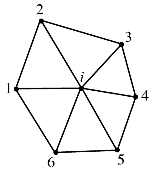
Figure 1.
Finite difference fan for mesh point i on a Delaunay mesh with neighbors 1–6.
There are two main advantages of this kind of meshing the calculation domain. First, a curved contour can be discretized very accurately compared to rectangular meshes. Second, we can rely on existing, very efficient implementations of those algorithms, such as the user friendly GMSH [7]. The output file contains lines with numbered mesh points and their coordinates, and lines with mesh point numbers and the connected triangles, which can be further processed to obtain the finite difference operators.
2.2. Finite Difference Operators for a Delaunay Mesh
A mesh-free finite-difference scheme is described in [8], in which a weighted least-square approximation procedure for unstructured mesh points is proposed. Since we utilize a Delaunay mesh, the least-square approximation can be adopted, but the weighting is not essential in this case.
For each point in the mesh, the following steps have to be taken to find the finite difference operators. The Taylor series up to the second derivatives of Equation (1) is rearranged in the following way:
The difference of a function value at a neighbor point j to the value at point i is . All spatial information from the mesh is contained in S and all the derivatives appear in :
The optimal derivative approximation by least-square means is
Note, that there is one line per neighboring point in the system of equations:
For practical implementation, the Moore-Penrose inverse can be used, which additionally ensures a solution in both an overdetermined situation () and the case of too few neighbor points (); for example, at a boundary. In any case, the matrix C contains nothing but coefficients which can be filled into the operator matrix for every mesh point, in the same manner as above with and .
3. Kelvin Transformation
The Kelvin transformation is a non-linear transformation that maps infinity to zero [9]. Since it is a radial transformation, i.e., the boundary of the calculation domain is a sphere for or a circle for , for a boundary circle with , the mapping of a position vector to is:
This means the infinite space outside the circle can be mapped to the finite space into the circle. The mesh for the two dimensional example geometry described in the next section is shown in Figure 2, in which the structure of interest lies in the inner domain shown on the left side. It is limited by a circular boundary with radius r. Note that this is not a limitation in general, because the structure of interest can have a geometry that is not necessarily circular and can also be of an irregular shape.
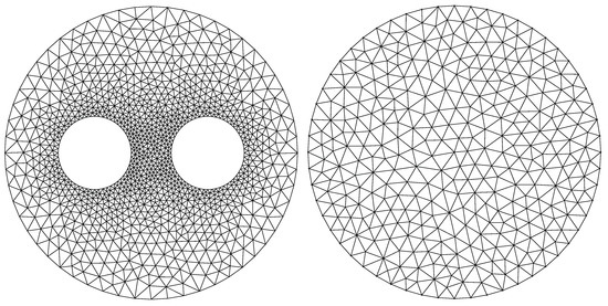
Figure 2.
Delaunay mesh for the inner (left) and outer domain (right) with 1194 and 337 mesh points.
From the coordinates of the mesh points lying on the boundary, a second circular mesh is created to which the outer domain is mapped by the Kelvin transformation. This second mesh is shown in Figure 2 on the right side.
As the center point of this second mesh corresponds to infinity, a Dirichlet boundary condition can be utilized to force potentials or fields to vanish in infinity. In the system matrix, the finite difference operators can be arranged corresponding to the differential equation that should be solved.
The complete system matrix does not only contain one line for every point in the inner region, but also lines for the points of the outer region in Figure 2. The spatial coordinates of the points at the boundaries, i.e., the two circles, are exactly the same. As a consequence, they only correspond to the mesh points as depicted in Figure 3. This is achieved by a Dirichlet boundary condition to link the equations in the matrix respectively.
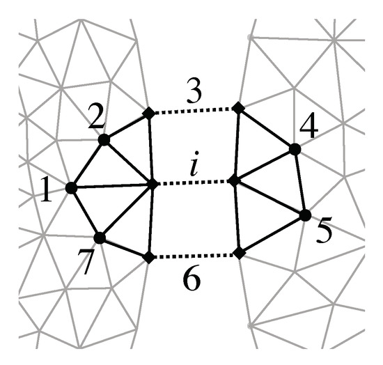
Figure 3.
Modification of differential operators to reach into the outer mesh.
Additionally, the operators in the inner region are expanded to reach across the boundary, which is done by adding the points 4 and 5 to the neighbor points of i and recalculate the coefficients with Equations (4) and (5). Now a “transparent” boundary for the inner domain is established at the cost of increasing the system of equations by the number of points of the outer domain.
4. Exemplary Potential Problem
To test the finite difference and Kelvin mapping implementation, an arrangement was chosen, for which an analytical solution exists: the transverse-electromagnetic (TEM) field mode of a two-wire transmission line. For TEM modes the fields are identical with the static case. Thus, it reduces to the problem of calculating the scalar potential .
In transmission line context, utilizing the characteristic impedance Z as a command variable is an obvious choice. Thus, in the next two sections deal with finding Z from both analytical and numerical solutions.
4.1. Analytical Solution
As an example geometry, a transmission line consisting of two parallel wires with circular cross sections (Figure 4) is suitable, as their scalar potential extends to infinity. For the sake of simplicity, a homogenous medium (vacuum) around the wires is assumed. Their axes lie in the -plane and intersect the x-axes at and R. The radius of the wires is .
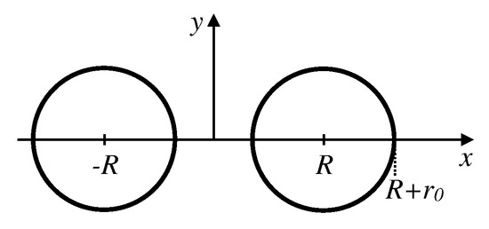
Figure 4.
Cross section of a symmetric two-wire arrangement with center distance and radii .
Assuming a potential difference U between the wires, the scalar potential of this arrangement can be found from the superposition of the scalar potentials of the individual wires [10]:
whereby . The characteristic impedance Z turns out to be:
Setting mm and mm results in Z to yield about .
4.2. Numerical Solution
For the static problem described above, a Laplace Equation (9) on the grid already shown in Figure 2 has to be solved.
The cross section two-wire arrangement consists of circles only, so that the occurring radii are all divided by the same integer factor to determine the characteristic length of mesh triangles around the corresponding circle. Setting the boundary radius mm and results, for the given geometry, in 1194 and 337 mesh points for the inner and outer calculation domains.
With the discrete second derivatives for all n mesh points and from Equation (5), the discrete 2D Laplacian can be built according to Equation (9): . The related system of equation becomes:
This can be solved for the vector , containing the figures for the scalar potential on the grid after applying a Dirichlet boundary condition at the mesh points of the left and right wires. These have to be set to the potentials and with in the vector by inserting a one at the main diagonal of and zero elsewhere in the related lines. The calculated values for on the grid are shown as contour plots in Figure 5.
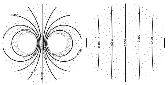
Figure 5.
Numerical solutions for on inner (left) and outer (right) meshes as equipotential lines.
With , the transverse electrical field components and are given by
By eyeballing Farady’s law and Ampère’s law in vacuum , one can see that for TEM waves in homogenous media, the magnetic field components and are related to the electrical field and the speed of light c as
The EM-fields calculated from using Equations (11) and (12) are shown in Figure 6. This field plot is only for illustration and the sake of completeness. The grayscale of the arrows represents the log-converted local field strength.
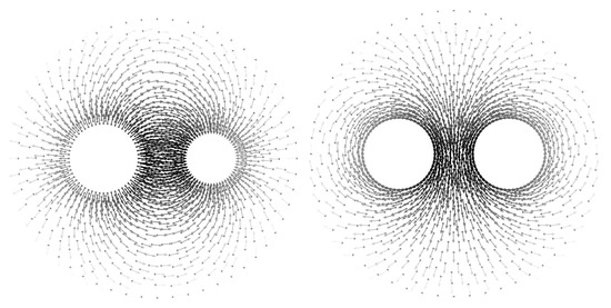
Figure 6.
Numerical solutions for electrical (left) and magnetic fields (right).
As expected, the electrical field is perpendicular to the conductors, whereas the magnetic field is parallel.
The electromagnetic power flow P from a field point of view corresponds to the absolute value of the Poynting vector integrated over the calculation domain A using oriented area elements :
which is identical to the transported power from a circuitry point of view. From that, the characteristic impedance Z of the transmission line can be calculated for a given potential difference U:
Note that the denominator in Equation (13) is just the field impedance in vacuum. In a similar way, transmission line parameters like the per unit length parameters can be found.
5. Evaluation
The combination of a non-rectangular grid with a radial transformation technique allows one to solve differential equations; e.g., potential problems or waveguide eigenmodes with a transparent boundary—i.e., with no distortion from a near artificial boundary condition. In two dimensions, the Kelvin transformation requires a circle as the boundary surrounding the structure of interest. In Figure 7 the potential calculated numerically with this transformation (left) is illustrated in contrast to the potential distorted from a radial (center) and a rectangular boundary (right) with a Dirichlet condition .
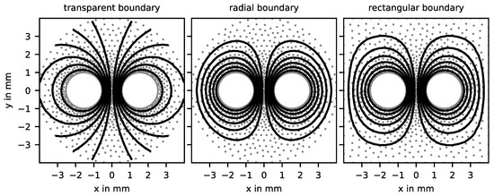
Figure 7.
Lines of equal potential of calculated numerically with a transparent boundary, i.e., a Kelvin transformation (left), and with a Dirichlet condition on a radial boundary (center) and a Dirichlet condition on a rectangular boundary (right).
The rectangular boundary has an edge length of mm, corresponding to the boundary radius of mm. The characteristic length of the two meshes is . In the following, the radial boundary is preferred, because the calculations are then performed on exactly the same (inner) mesh with and without Kelvin transformation.
The relative error of with respect to the analytical solution is shown in Figure 8. It is calculated as follows:
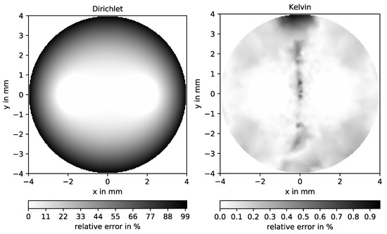
Figure 8.
Relative error of for a Dirichlet (left) and Kelvin boundaries (right). Note the different scales in both diagrams.
On the left, again a Dirichlet condition on the boundary circle is employed.
The error is maximal on the artificial boundary, whereas the Kelvin mapping approach produces only a very small error, as shown on the right of Figure 8. Only points where the figures of are significant, i.e., , were taken into account in the diagrams. Nevertheless, the maximal error is located near the symmetry axes, where the values of are very close to zero. This asymmetry is due to numerical uncertainties only, so that the remaining error can be completely attributed to the discretization error. Consequently, the proposed method does not suffer from the impact of artificial boundaries of the computation domain.
For further investigations, the actual target value, i.e., the characteristic impedance Z, is used. Since the characteristic length in the mesh is determined by only, it is used as the parameter for the examination of convergence instead of a more complicated mesh refinement scheme. For a parameter sweep of the relative error of Z is plotted against the resulting number of mesh points in Figure 9.
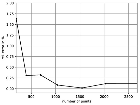
Figure 9.
Convergence: Relative error of Z over the number of mesh points.
From about 500 mesh points on, the approximated value for the characteristic impedance is very close to the analytic one. At 1000 mesh points the relative error drops below 0.25%. For , i.e., 1531 mesh points, it is even less, so that this configuration was chosen.
The numerical solution with Dirichlet or Neumann boundary conditions approaches the solution of the unbounded calculation domain with increasing distance of the boundary to the region of interest in the mesh. This is depicted in Figure 10 for boundary radii of mm and mm.
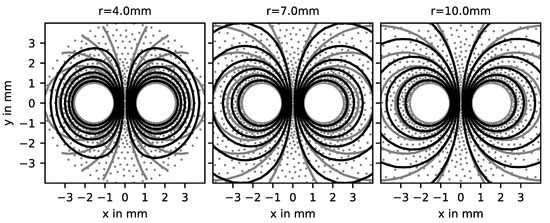
Figure 10.
Equipotential lines of of a two-wire line for different boundary radii. Numerical solution with the Dirichlet boundary condition (black), and the analytical solution (gray).
It clearly shows that the lines of equal potential are deformed in the case of too tight a boundary, and get closer to the analytical solution for a more remote boundary. This dependence on the boundary radius is also shown in Figure 11.
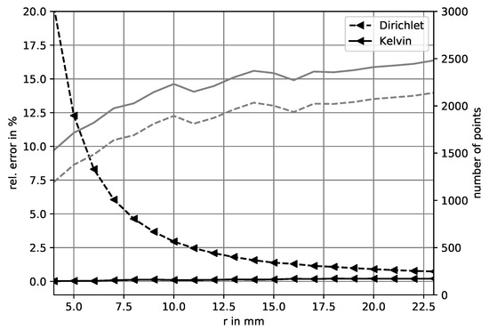
Figure 11.
Relative error of Z for increasing boundary radius and number of points (gray lines) with and without outer region.
The characteristic impedance approaches the true value for increasing boundary radius. It can be seen that for a relative error below % the radius must be larger than mm resulting in a mesh size of more than 2000 points. Since the approach presented here delivers the same value for any distance to the boundary apart from some discretization error, it outperforms the conventional solution. For example, a radius of mm can be used which results in about 1500 mesh points including the additional outer mesh points.
6. Conclusions
The presented approach is based on a finite difference implementation using a 2D Delaunay mesh. This allows for adequate discretization of a circular boundary. The circular boundary is not a limitation compared to the usually employed rectangular boundaries. To make this circular boundary transparent, an additional outer mesh is added. On this, a Kelvin mapping of the coordinates is performed, which results in an outer region being mapped to the inner of a circle, wherein infinity becomes the center point.
Using finite differences leads to a straightforward implementation of many differential equations. In this case, the calculation of an electrical scalar potential was used as an example. The numerical solution of a two-wire arrangement was compared to its analytical solution to demonstrate the performance of the presented approach. Moreover, it was shown that despite of the additional outer mesh, in total a smaller equation system is sufficient to achieve comparable results.
In future developments, e.g., a boundary element method or a Greens function approach for an outer homogenous region could be used to reduce the number of equations even more. The field of application for the presented transparent boundary could be a 2D solver for transmission lines and waveguides, a waveguide port for a 3D field solver, or a full 3D solver with a spherical mesh boundary for unbounded EM problems.
Funding
This research received no external funding.
Acknowledgments
The author is grateful to Prof. Helmreich for his support and encouragement.
Conflicts of Interest
The authors declare no conflict of interest.
References
- Nagel, T.; Görke, U.J.; Moerman, K.M.; Kolditz, O. On advantages of the Kelvin mapping in finite element implementations of deformation processes. Environ. Earth Sci. 2016, 75, 937. [Google Scholar] [CrossRef]
- Lowther, D.A.; Freeman, E.M.; Forghani, B. A sparse matrix open boundary method for finite element analysis. IEEE Trans. Magn. 1989, 25, 2810–2812. [Google Scholar] [CrossRef]
- Farah, A.A.M.; Afonso, M.M.; Vasconcelos, J.A.; Schroeder, M.A.O. A Finite-Element Approach for Electric Field Computation at the Surface of Overhead Transmission Line Conductors. IEEE Trans. Magn. 2018, 54, 1–4. [Google Scholar] [CrossRef]
- Sugahara, K.; Kameari, A.; Ebrahimi, H.; Shindo, Y.; Matsuo, T. Finite-Element Analysis of Unbounded Eddy-Current Problems Using Cauer Ladder Network Method. IEEE Trans. Magn. 2018, 54, 1–4. [Google Scholar] [CrossRef]
- Lai, M.C.; Li, Z.; Lin, X. Fast solvers for 3D Poisson equations involving interfaces in a finite or the infinite domain. J. Comput. Appl. Math. 2006, 191, 106–125. [Google Scholar] [CrossRef][Green Version]
- Jiang, H.L.; Cui, T.J. Efficient PML Implementation for Approximate CN-FDTD Method. IEEE Antennas Wirel. Propag. Lett. 2019, 18, 698–701. [Google Scholar] [CrossRef]
- Geuzaine, C.; Remacle, J. Gmsh: A 3-D finite element mesh generator with built-in pre- and post-processing facilities. Int. J. Numer. Methods Eng. 2009, 79, 1309–1331. [Google Scholar] [CrossRef]
- Ding, H.; Shu, C.; Yeo, K.; Xu, D. Development of least-square-based two-dimensional finite-difference schemes and their application to simulate natural convection in a cavity. Comput. Fluids 2004, 33, 137–154. [Google Scholar] [CrossRef]
- Dassios, G. The Kelvin transformation in potential theory and Stokes flow. IMA J. Appl. Math. 2008, 74, 427–438. [Google Scholar] [CrossRef]
- Helmreich, K. Entwurfsdatengesteuerte Fehleranalyse in Gemischt Analog-Digitalen Hochgeschwindigkeitsschaltungen Durch Spannungs- und Strommessungen mit Einem Elektronenstrahltester. Ph.D. Thesis, Friedrich-Alexander-Universität Erlangen-Nürnberg, Erlangen, Germany, 1992. [Google Scholar]
© 2020 by the author. Licensee MDPI, Basel, Switzerland. This article is an open access article distributed under the terms and conditions of the Creative Commons Attribution (CC BY) license (http://creativecommons.org/licenses/by/4.0/).