Article

Complex Dynamics of a Novel Chaotic System Based on an Active Memristor

Key Laboratory for Robot and & Intelligent Technology of Shandong Province, Shandong University of Science and Technology, Qingdao 266590, China
*
Author to whom correspondence should be addressed.
Electronics 2020, 9(3), 410; https://doi.org/10.3390/electronics9030410
Submission received: 4 February 2020 / Revised: 26 February 2020 / Accepted: 27 February 2020 / Published: 28 February 2020
(This article belongs to the Section Circuit and Signal Processing)

Abstract

:
On the basis of the bistable bi-local active memristor (BBAM), an active memristor (AM) and its emulator were designed, and the characteristic fingerprints of the memristor were found under the applied periodic voltage. A memristor-based chaotic circuit was constructed, whose corresponding dynamics system was described by the 4-D autonomous differential equations. Complex dynamics behaviors, including chaos, transient chaos, heterogeneous coexisting attractors, and state-switches of the system were analyzed and explored by using Lyapunov exponents, bifurcation diagrams, phase diagrams, and Poincaré mapping, among others. In particular, a novel exotic chaotic attractor of the system was observed, as well as the singular state-switching between point attractors and chaotic attractors. The results of the theoretical analysis were verified by both circuit experiments and digital signal processing (DSP) technology.

1. Introduction

The memristor postulated by Chua in 1971 [1] is a nonlinear device with memorability, whose resistance depends on the history of the current (or voltage). Due to the lack of physical verification, it has not attracted much attention in the scientific community for over 30 years. The memristor theory and resistive switching was linked by HP lab in 2008 for the first time [2], which experimentally confirmed Chua’s theoretical hypothesis. Due to potential applications of memristors, it caused a booming interest in many research fields today, including the nonvolatile memory [3,4], artificial intelligence [5,6], neural networks [7,8], nonlinear chaotic circuits [9,10], and other fields.
As a nonlinear device, memristors are introduced to design chaotic circuits [11,12,13]. Some memristor-based nonlinear oscillators were created by replacing Chua’s diodes with memristors, and the dynamical behaviors of these systems were analyzed and explored [14]. Other memristor-based chaotic circuits were reported by Muthuswamy, who provided a generation frame of chaotic sequence for secure communications [15]. A simplest memristor-based chaotic circuit was presented with only three elements in series, whose physical circuit was designed by using solid electronic components, successfully realizing the chaotic oscillation of the system [16]. A generic passive memristor was presented, which was used to design a second-order nonlinear oscillator system [17]. An active memristor based on it was devised and explored in this paper.
Multistable systems are a hot topic recently [18,19,20]. In general, a system is deemed to be multistable if it is neither stable nor completely unstable and switches between several mutually exclusive states over time. A simplest memristor-based circuit with hidden multistable states was previously analyzed, and the generation mechanism of coexisting attractors was confirmed [21]. A memristive Chua’s circuit with the multistability was proposed, and the line equilibrium point and the stability of the system were analyzed and confirmed [22]. The multistability means that the system has coexisting attractors. The coexistence of attractors, as a permanent subject, has been analyzed and explored in some chaotics systems [23,24,25]. A memristive system has been presented that has four diverse coexisting attractors: an equilibrium point, a stable limit cycle, a 16-peak periodic attractor, and a strange attractor [26]. A simple chaotic system with various types of multiple coexisting attractors has been presented, and its physical circuit has been realized, displaying the chaotic behaviors [27]. Moreover, some memristive systems with multiple coexisting attractors and even infinitely many attractors have been proposed [28,29,30,31]. A parallel inductor-capacitor-memristor circuit has been constructed, which showed the coexistence of multiple attractors [32]. In fact, the above-mentioned systems all own heterogeneous multistability. However, if there are several or even infinitely more coexisting attractors with different properties in a system, the system will be regarded as having heterogeneous multistability [33]. This phenomenon is interesting and stimulates the desire to explore the heterogeneous multistability. Therefore, a memristor-based chaotic system with heterogeneous multistability was presented by some preliminary experiments in this paper.
This paper devised an emulator of the active memristor, which can maintain the stability of hysteresis loops over a wide range of frequencies. A memristor-based fourth-order chaotic system with a novel exotic attractor was proposed, which had complex dynamics, including chaos, coexisting attractors, transient chaos, and heterogeneous multistability. A novel phenomenon, switching between a point attractor and a chaotic attractor, was found with the change of the initial values. The remainder of this paper is organized as follows: the AM is presented and its emulator is implemented by Multisim in Section 2. A memristive chaotic oscillator was constructed and the stability of the equilibria of the system is analyzed in Section 3. Dynamics of the proposed system are explored, including symmetry, coexisting bifurcations, coexisting attractors, and multistability, in Section 4. The results of circuit implementation and digital signal processing (DSP) implementation of the memristor-based chaotic system are introduced in Section 5. Finally, some conclusions are given in the last section.

2. Memristor Model and its Emulator

2.1. An Active Memristor

A memristor, as a two-port electronic component, has a magnetic flux ϕ that is a nonlinear continuous function of its charge q [1]. The generalized memristive system was postulated by Chua in 1976 [34], defined as follows:
{ x ˙ = f ( x , u , t ) y = g ( x , u , t ) u
where x represents the internal state of the system, and u and y represent the input and output of the system, respectively. The bistable bi-local active memristor (BBAM) presented in [17] is described by the memconductance W(x), as follows:
W ( x ) = x 2 ( t )
The dynamics of the memristor are
{ d x ( t ) d t = x ( t ) | x ( t ) | + A x ( t ) + B v ( t ) i M ( t ) = W ( x ) v ( t )
where x(t) represents the memristive state and changes nonlinearly over time t, v(t) is the input, and i M ( t ) represents the output of the memristor. The instantaneous power of the BBAM is obtained as
p ( t ) = W ( x ) v 2 ( t ) = x 2 ( t ) v 2 ( t ) 0
When t t 0 , the integration of the energy from t 0 to t satisfies
t 0 t p ( τ ) d τ 0
Therefore, it was passive. However, an active device is feasible and effective for designing the chaotic circuit. Thus, a composite component named active memristor was constructed by using the memristor with a negative conductance in parallel, as shown in Figure 1.
According to the Kirchhoff’s law and the properties of the component, the dynamics of the active memristor are described as follows:
{ d x ( t ) d t = x ( t ) | x ( t ) | + A x ( t ) + B v ( t ) i M ( t ) = [ x 2 ( t ) G ] v ( t )

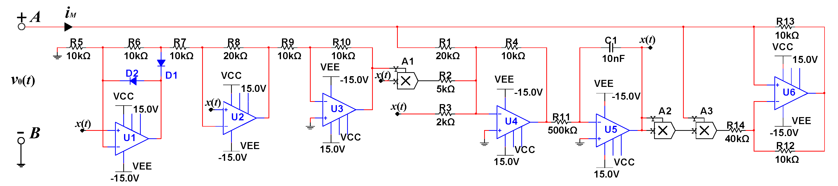
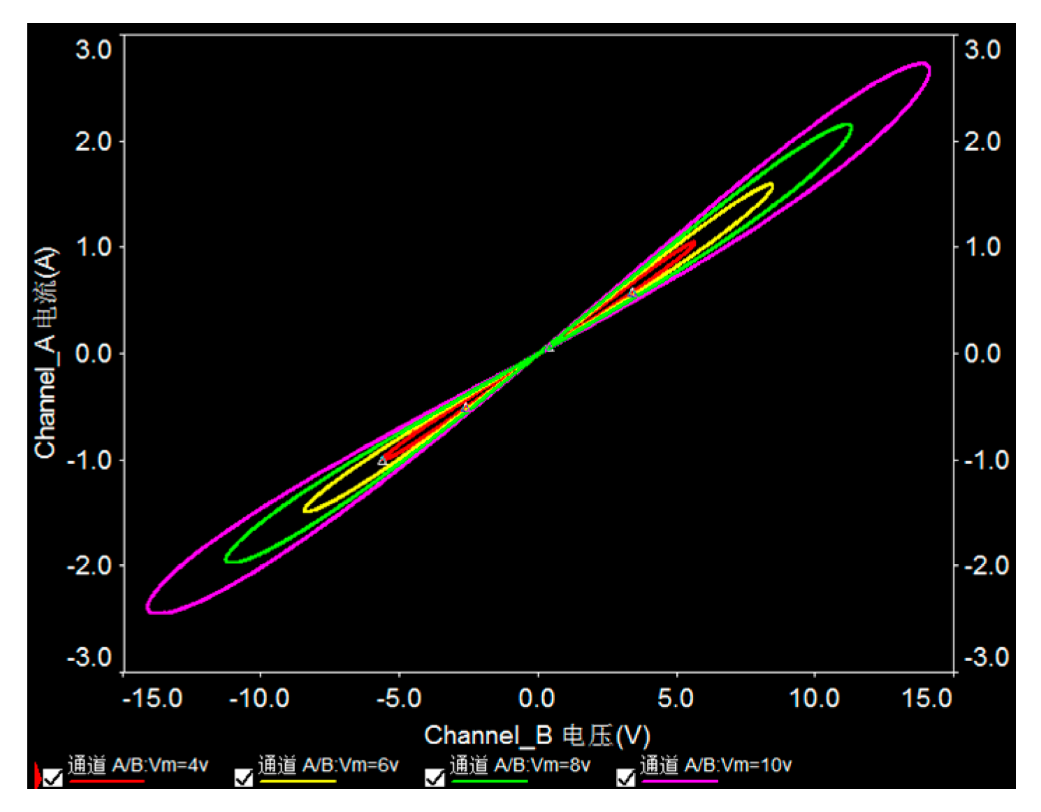
2.2. Memristive Emulator

A memristive emulator was designed to explore the electrical performance of the memristor by utilizing the basic circuit theory in this subsection. On the basis of the addition, subtraction, multiplication, division, integration, and differentiation of input voltage easily realized in series and parallel circuits of operational amplifiers, multipliers, and other devices, the emulator of the active memristor (AM) was designed by using off-the-shelf electronic components for confirming volt-ampere fingerprints of the memristor.
According to Equation (6), the relationship between the internal state x(t) of the system and the input voltage v(t) is
x ( t ) = x ( 0 ) + 0 t [ x ( τ ) | x ( τ ) | + A x ( τ ) + B v ( τ ) ] d τ
where x(0) is an initial value of memristive internal state and obtained below:
x ( 0 ) = 0 [ x ( τ ) | x ( τ ) | + A x ( τ ) + B v ( τ ) ] d τ
It can be seen from Equations (7) and (8) that the different values of x(0) can cause the variation of memconductance of the AM, indicating the characteristics of memory of the memristor. To facilitate the circuit emulator of the memristor, consider the initial value x(0) = 0. According to Equations (6)–(8), one gets
i M ( t ) = { ( 0 t [ x ( τ ) | x ( τ ) | + A x ( τ ) + B v ( τ ) ] d τ ) 2 G } v ( t )
Thus, a memristive emulator based on Equation (9) was devised, which was composed of six operational amplifiers, three multipliers, and some resistors as shown in Figure 2. The voltage v 0 ( t ) between nodes A and B is the input of the emulator. Define the output voltage v U 5 of the amplifier U5 as the internal state x(t) of the memristor. When the output voltage x(t) of the amplifier U5 passes through an absolute circuit consisting of two amplifiers U1 and U2, two diodes D1 and D2 and some resistors, signal x(t) implements the absolute value operation, i.e., x(t)→| x(t)|. Thereafter, the signal |x(t)| is converted to −|x(t)| through the inverter consisted of U3, R9, and R10. The signals −|x(t)| and x(t) are converted to −|x(t)|x(t) through the multiplier A1, which is to be the input of the adder consisting of U4, R1, R2, R3, and R4. Next, at the output of the amplifier U4, the voltage v U 4 is
v U 4 ( t ) = R 4 R 2 x ( t ) | x ( t ) | R 4 R 3 x ( t ) R 4 R 1 x ( t )
The voltage signal v U 4 passes through the inverter integrator consisting of U5, C1, and R11, and the internal state x(t) is obtained below:
x ( t ) = 0 t v U 4 ( τ ) d τ = 1 R 11 C 1 0 t [ R 4 R 2 x ( τ ) | x ( τ ) | + R 4 R 3 x ( τ ) + R 4 R 1 v 0 ( τ ) ] d τ
From the signal x(t), through the multipliers A2 and A3, the voltage v A 3 = x 2 ( t ) v 0 ( t ) is obtained at the output of multiplier A3. Finally, the volt-ampere characteristics of the AM are derived through the amplifier U6, as follows:
i M = R 12 R 13 { 1 R 14 { 1 R 11 C 1 0 t [ R 4 R 2 x ( τ ) | x ( τ ) | + R 4 R 3 x ( τ ) + R 4 R 1 v 0 ( τ ) ] d τ } 2 1 R 14 } v 0 ( t )
Let the capacitor C1 and the associated resistors take the corresponding parameter values in Figure 2, and the pinched hysteresis loops of the memristor are observed, as shown in Figure 3, with the driven voltage v(t) = Umsin(2πft), Um = 6 V, and different frequencies. It can be seen from the figure that these curves pass through the origin on the volt-ampere plane. The memristor has complex dynamics behaviors under the driven signal with the low frequencies, such as f = 15 Hz, 30 Hz, and 40 Hz, as shown in Figure 3a. It tends to a single value curve as the frequency continually increases, as shown in Figure 3b. When the frequency of the applied signal tends to infinity, the memristor degenerates into a linear resistance. This indicates that the memristor satisfies the frequency-dependence. Moreover, it is noteworthy that the hysteresis loops keep the symmetrical font “8” when the frequency is higher than 300 Hz, with a wide range of stable frequency.
The evolution of pinched hysteresis loops of the AM emulator was obtained, as shown in Figure 4, with the frequency f = 650 Hz and different amplitudes Um = 10 V, Um = 8 V, Um = 6 V, and Um = 4 V. It can be seen from the figure that the pinched hysteresis loop of the memristor was compressed and the shape remained unchanged as the amplitude of the applied voltage signal decreased, with the frequency f = 650 Hz. The Multisim circuit experiment indicated that the features of the memristor depend on the amplitude and frequency of the applied voltage.

3. Chaotic Circuit Topology and Circuit Dynamics

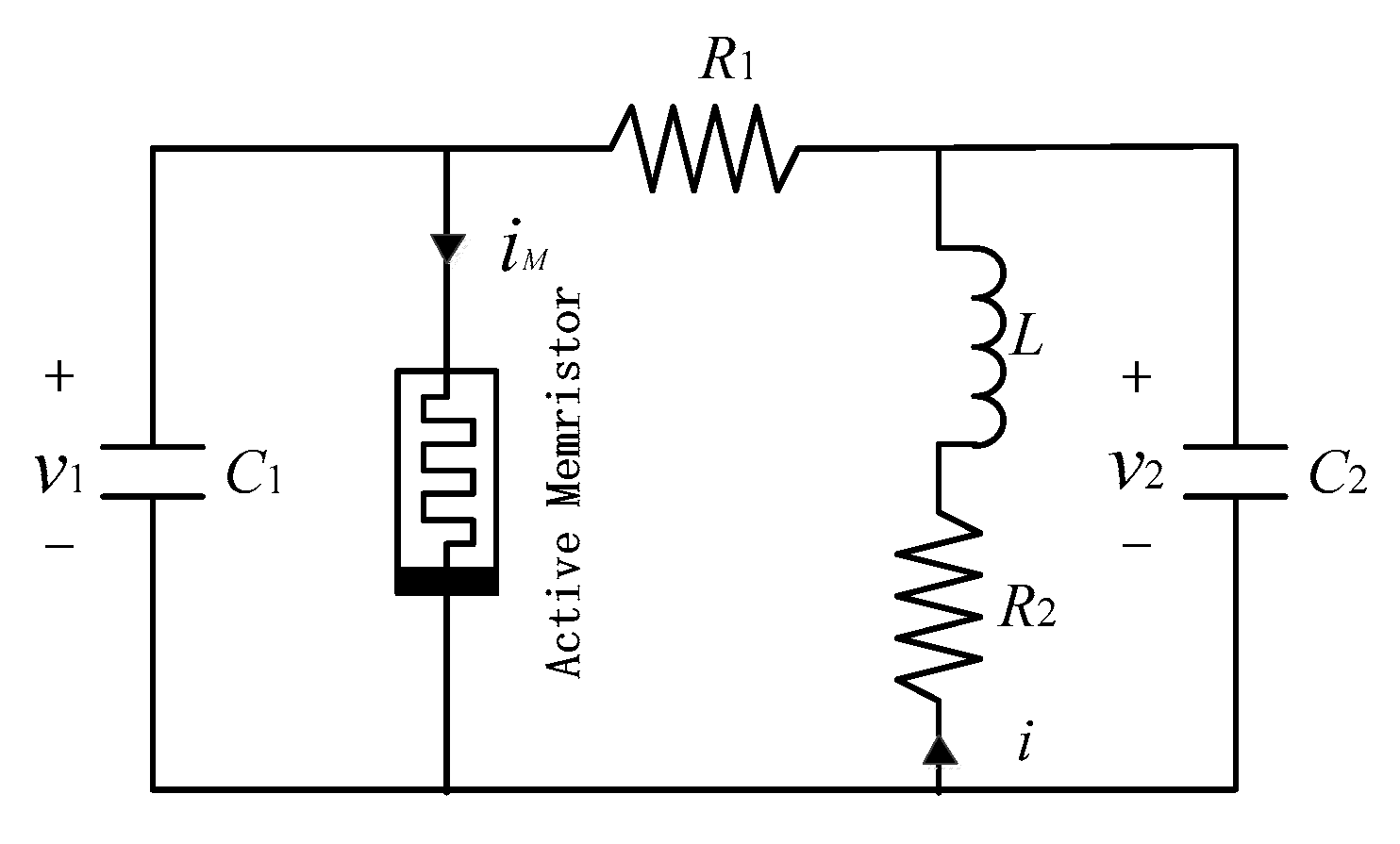
3.1. Chaotic Circuit Ttopology

The memristor-based chaotic circuit was designed, with two resistors, an inductance, two capacitors, and the active memristor, as shown in Figure 5.
According to Kirchhoff’s laws, the dynamics of the system are described as
{ d v 1 d t = 1 R 1 C 1 ( v 2 v 1 + G R 1 v 1 R 1 φ 2 v 1 ) d v 2 d t = 1 R 1 C 2 ( v 1 v 2 + R 1 i ) d i d t = 1 L v 2 R 2 L i ) d φ d t = φ | φ | + A φ + B v 1
where ϕ is a magnetic flux of the memristor, and v1 and v2 are voltages of capacitors C1 and C2, respectively. Let x = v 1 , y = v 2 , z = i , ϕ = φ, a = 1 C 1 , b = 1 L , c = R 2 L , h = G, C2 = 1, and R1 = 1, and Equation (13) is reset below
{ x ˙ = a ( y x + h x φ 2 x ) y ˙ = x y + z z ˙ = b y c z φ ˙ = φ | φ | + A φ + B x
Let the parameters of Equation (14) be fixed as in Table 1, and a novel attractor is found in Equation (14), as shown in Figure 6, with the initial conditions (0, 0.001, 0, 0).
As can be seen in Figure 6b, the attractor is comprised of two scroll shape attraction disks and bonding brands, with a small scroll on the upper and a large scroll on the lower. The trajectory is folded vertically from the center of the small scroll and goes to the periphery of the scroll. The outer trajectory is spirally rotated from the outer to the inner of the large scroll. Then, the trajectory from the center of the large scroll is vertically folded into the outer periphery of the small scroll. Thereafter, it spirally rotates into the center of a small scroll and keeps repeating, forming the novel attractor. The phase diagram in Figure 6a is the projection of the large scroll and the small scroll in the (x, y, z) space. It can be seen from Figure 6c that the inner circumference of the large scroll overlaps with the outer one in a small scroll. Figure 6f shows the projection of the attractor on the (x, φ) plane, which is a manifestation of a backward and forward folding perpendicular to the (x, φ) plane at the upper and lower vertical lines of x = 0. Combing Figure 6d,e, the running law of the trajectory is clear. In addition, the Lyapunov exponents of the system are LE1 = 0.4488, LE2 = 0, LE3 = −2.3519, and LE4 = −58.0488, and the Lyapunov dimension of this attractor is obtained below:
D L = j + 1 | L E j + 1 | i = 1 j L E i = 3 + L E 1 + L E 2 + L E 3 L E 4 = 3.0328
These indicate that the attractor of the system is chaotic. Further, the Poincaré mapping of the trajectory on the (y, z) plane is confirmed, as shown in Figure 7a, and the time domain waves of x, y, z, and φ are reported, as shown in Figure 7b, which indicates that the system is the aperiodicity and pseudorandomness.
In short, the system is a chaotic oscillator system, which is confirmed by using the phase diagrams, Poincaré mapping, time-domain waves, the Lyapunov exponents, and its corresponding dimensions.

3.2. Stability of the System

Let the parameters be fixed as in Table 1, and x ˙ = y ˙ = z ˙ = φ ˙ = 0 , and the equilibria of Equation (14) are obtained as
E 1 = { ( x ,   y ,   z , φ ) | x = y = z = φ = 0 }
E 2 , 3 = { ( x ,   y ,   z , φ ) | x = y = z = 0 , φ = ± 5 }
E 4 , 5 = { ( x ,   y ,   z , φ ) | x = ± 0.004917 , y = ± 0.000032 , z = 0.004885 , φ = 4.8996 }
At the equilibrium of the system, the Jacobian matrix J is
J = [ a ( h 1 φ 2 ) a 0 2 a x φ 2 1 1 1 0 0 b c 0 100 0 0 5 φ sign ( φ ) | φ | ]
When the system parameters are set as in Table 1, accordingly the characteristic equation is
a 10 λ 4 + a 1 1 λ 3 + a 1 2 λ 2 + a 1 3 λ + a 1 4 = 0
where
  • a 10 = 1
  • a 11 = | φ | + φ 2 sign ( φ ) + 7.5 φ 2 182.7
  • a 12 = 7.5 φ 2 | φ | 177.7 | φ | + 7.5 φ 3 sign ( φ ) + 1500 x φ 177.7 φ sign ( φ ) 20.25 φ 2 + 667.3
  • a 13 = 17.25 φ 2 | φ | 221.2 | φ | + 17.25 φ 3 sign ( φ ) + 3450 x φ 221.2 φ sign ( φ ) + 1416 φ 2 34957.75
  • a 14 = 1502.25 φ 2 | φ | 36063.75 | φ | + 1502.25 φ 3 sign ( φ ) + 300450 x φ 36063.75 φ sign ( φ ) 7511.25 φ 2 + 180318.75
One has Δ 0 = a 10 , Δ 1 = a 11 , Δ 2 = a 10 a 13 a 11 a 12 a 11 , Δ 3 = a 11 a 14 a 13 Δ 2 Δ 2 , and Δ 4 = a 14 , where symbols Δ 0 , Δ 1 , Δ 2 , Δ 3 , and Δ 4 are the first column of the Routh table. On the basis of the Routh Criterion, if Δ 0 , Δ 1 , Δ 2 , Δ 3 , and Δ 4 are all positive, and the eigenvalues of the system are all negative, then the equilibrium of the system is stable. Otherwise, it is unstable.
At the equilibrium E1, the four values Δ 0 = 1, Δ 1 = −182.7, Δ 2 = 667.3, Δ 3 = −34,957.75, and Δ 4 = 180,318.75 were not all positive, and the eigenvalues of the system were λ1 = 0.0500, λ2 = 1.8004, and λ3,4 = −0.0017 ± 0.1410iλ1 and λ2 are the positive real numbers, and λ3 and λ4 are a pair of conjugate complex numbers with a negative real part. Therefore, E1 is an unstable saddle focus with index 2, foreshadowing the emergence of chaos.
At the equilibria E2 and E3, the four positive values Δ 0 = 1, Δ 1 = 14.8, Δ 2 = 87.2426, Δ 3 = 1276.8, and Δ 4 = 7462.5 determine that points E2 and E3 are unstable. The eigenvalues were λ1 = −5.0000, λ2 = −7.6984, and λ3,4 = −1.0508 ± 13.8840iλ1 and λ2 are negative real numbers, and λ3 and λ4 are a pair of conjugate complex numbers with a negative real part. Thus, E2 and E3 are stable foci.
Similarly, at the equilibria E4 and E5, the corresponding Δ 0 = 1, Δ 1 = 7.1487, Δ 2 = 2376.3566, Δ 3 = 5208.8159, and Δ 4 = 723,859.588 were all positive, and the eigenvalues were λ1 = −8.9473, λ2 = 4.1657, and λ3,4 = −1.1766 ± 13.8809i. The eigenvalue λ1 is a negative real number, λ2 is a positive real number, and λ3 and λ4 are a pair of conjugate complex numbers with the negative real part. Hence, E4 and E5 are the unstable saddle foci with index 1.

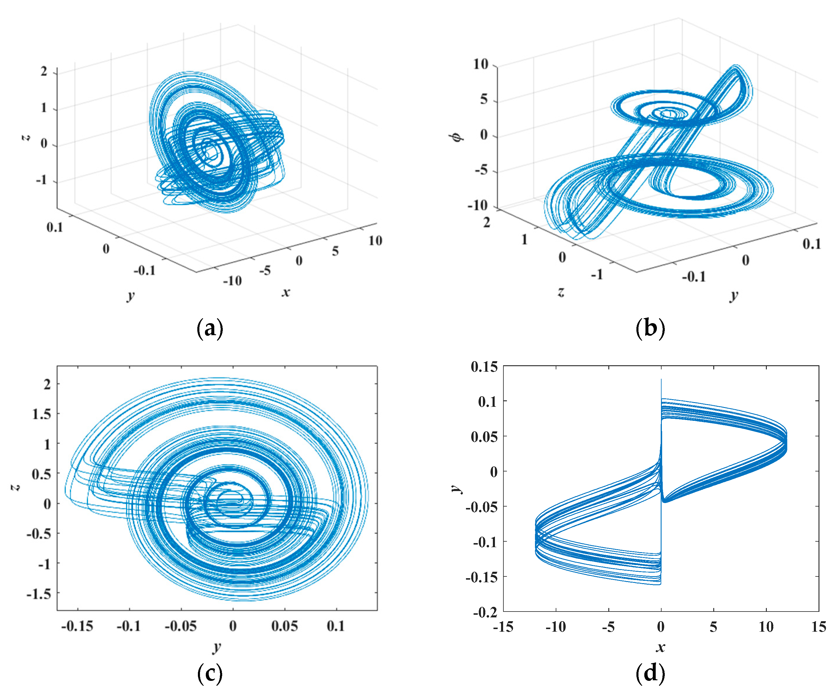
4. Dynamics of the Memristor-Based Oscillator

4.1. Symmetry

Equation (14) is invariant when state variables (x, y, z, φ) are transformed into (−x, −y, −z, −φ), i.e., Equation (14) is symmetric with respect to the origin O (0, 0, 0, 0). Let the parameters of Equation (14) be set as in Table 1, and the phase diagrams of the typical attractors are obtained, as shown in Figure 8 with two symmetrical initial conditions, (0, 2, 0, 0) and (0, −2, 0, 0). It can be seen from Figure 8 that each of the two attractors is asymmetric, and that they are symmetric to each other with respect to the origin.

4.2. Dynamics of the Memristor-Based Oscillator with the Varying Parameter c

The dynamics of the system are analyzed with the varying parameter c in this subsection. The Lyapunov exponents and the corresponding bifurcation diagram were calculated, as shown in Figure 9, where the parameter c varies in the interval (0.4, 1.5), and other circuit parameters remained unchanged as in Table 1. It is seen from Figure 9 that the system had multiple periodic oscillations and chaotic oscillations. The period-1 attractors existed in the interval c (0.4, 0.6), the period orbits evolved from period-1 to multiple periods through doubling bifurcation in the interval c (0.4, 0.79), and the chaotic states with several periodic windows existed in the interval c (0.79, 1.5). The phase portraits of the corresponding periodic and point attractors were given, as shown in Figure 10, with different parameters c.

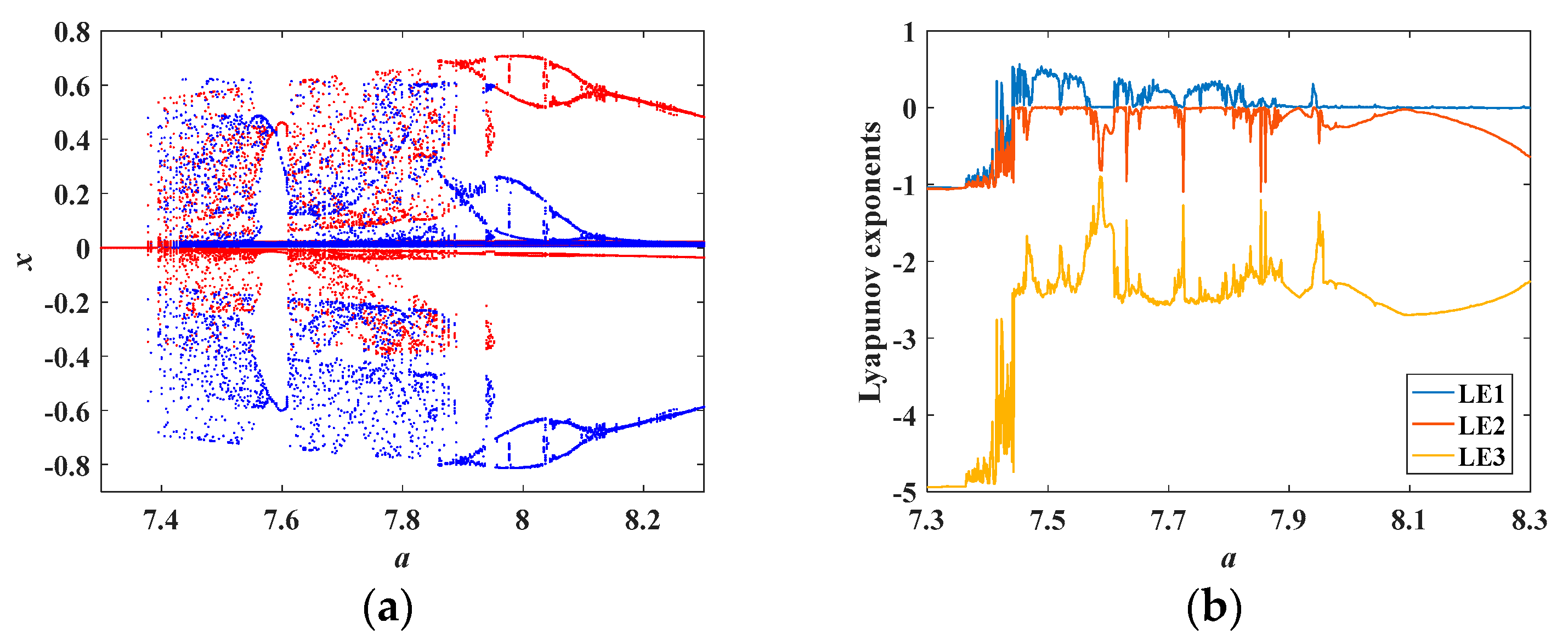
4.3. Coexisting Bifurcation and Coexisting Attractors with the Varying Parameter a

The coexisting bifurcation is a bifurcation phenomenon that depends on initial conditions. Considering the change of the parameter a and other circuit parameters as in Table 1, the coexisting bifurcation diagram was obtained, as shown in Figure 11a, where the orbit colored with red originated from initial conditions (0, 0.001, 0, 0) and those colored in blue started from initial conditions (0, −0.001, 0, 0, 0). It can be seen from Figure 11a that the dynamical evolution of the memristor-based chaotic system was that from the convergence point to chaotic orbit by period-doubling bifurcations as the parameter a increased. In addition, several periodic windows were observed in the chaotic region. The corresponding Lyapunov exponents further confirmed the dynamics of the system, as shown in Figure 11b.
Using the phase diagram, the evolution of the coexisting attractors was analyzed with the varying parameter a. Several coexisting attractors were obtained, as shown in Figure 12, with different initial conditions (0, 0.001, 0, 0) and (0, −0.001, 0, 0). The attractors from initial conditions (0, 0.001, 0, 0) are painted red and the counterpart from (0, −0.001, 0, 0) are blue. It can be seen from Figure 12 that the coexisting attractors evolved from a pair of symmetrical point attractors to symmetrical chaotic attractors, then to a period-2 attractor pair, and finally to a period-1 attractor pair. This is consistent with the dynamics of the system in Figure 11.

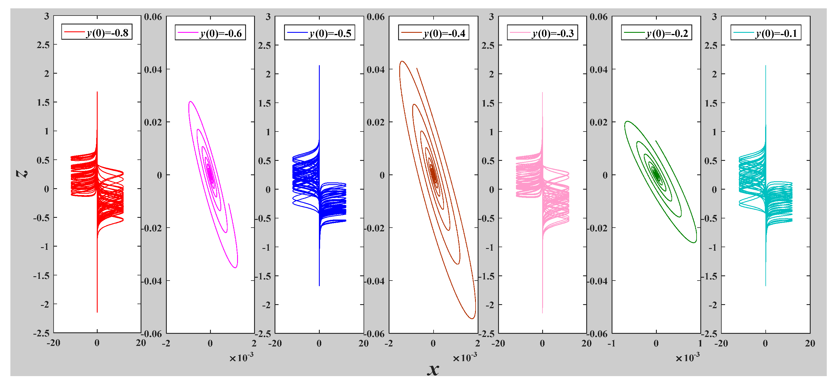
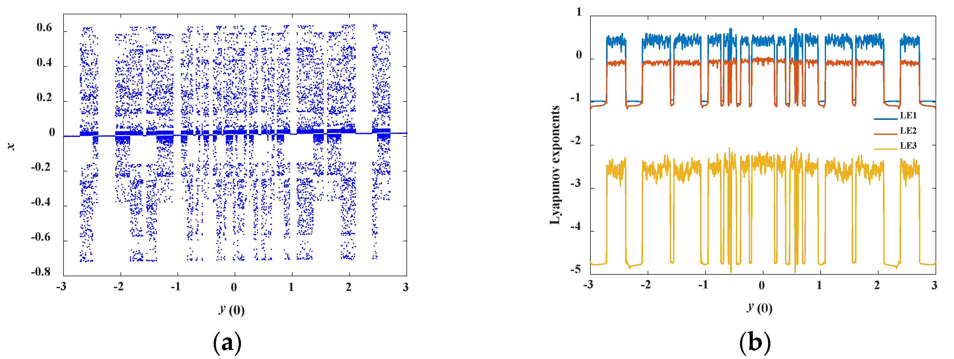
4.4. Heterogeneous Multistability

If several or even infinite kinds of coexisting attractors are found in a dynamics system, then the system has heterogeneous multistability [35]. The typical attractors can be obtained as shown in Figure 13, when the system parameter values were set as in Table 1 and the initial conditions are (0, y(0), 0, 0). It can be seen from this figure that the point attractors and chaotic attractors switched with the change of component y(0) of the initial conditions. The corresponding Lyapunov exponents and bifurcation diagrams were calculated, as shown in Figure 14. It can be seen from Figure 14 that the system had state-switching between point attractors and chaotic attractors. The point attractors and chaotic attractors are two kinds of attractors with different properties. Thus, the system has heterogeneous multistability.

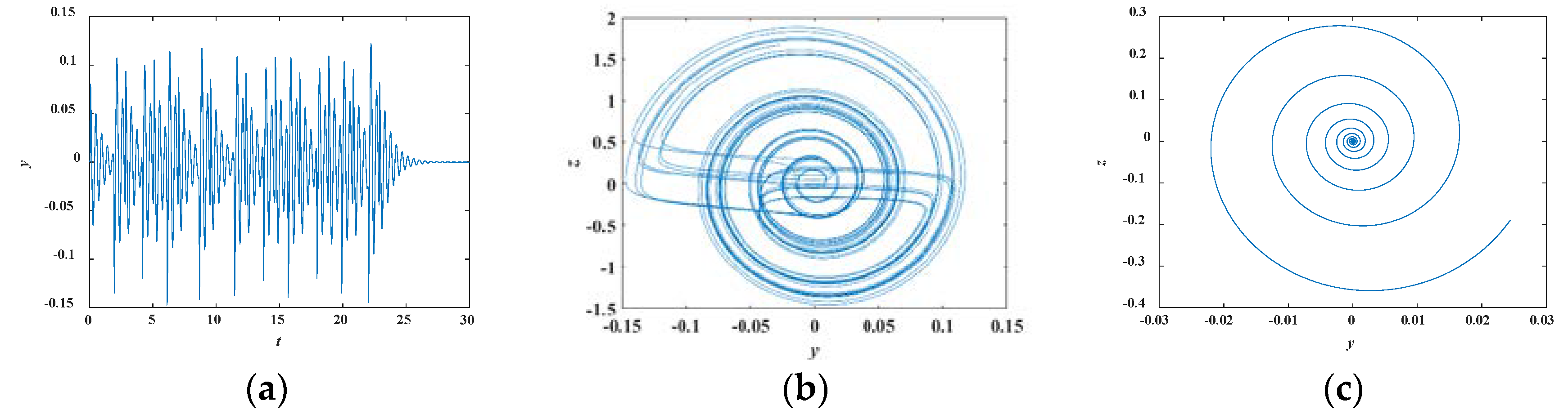
4.5. Transient Chaos

Let the parameter c = 1.42 and other parameters remain unchanged as in Table 1, and the time domain wave of the state y is displayed, with the initial conditions (0, 0.001, 0, 0), as shown in Figure 15a, which confirms the system has a transient oscillation. To observe the specific evolution of the corresponding orbits, the attractors with different time durations on the (y, z) plane were found, as shown in Figure 15b,c.
It can be seen from Figure 15 that the system state was chaotic at the time duration t = 0–23, and the corresponding attractor on the y-z plane is shown in Figure 15b. In addition, the amplitude of the state y gradually decreased to zero over time t, and the corresponding trajectory is shown in Figure 15c. This indicated that the system has transient chaos.
In short, the system has the symmetrical coexisting attractors, transient chaos, and heterogeneous multistable states. Additionally, an interesting state-switching between different attractors was found with the varying initial component.

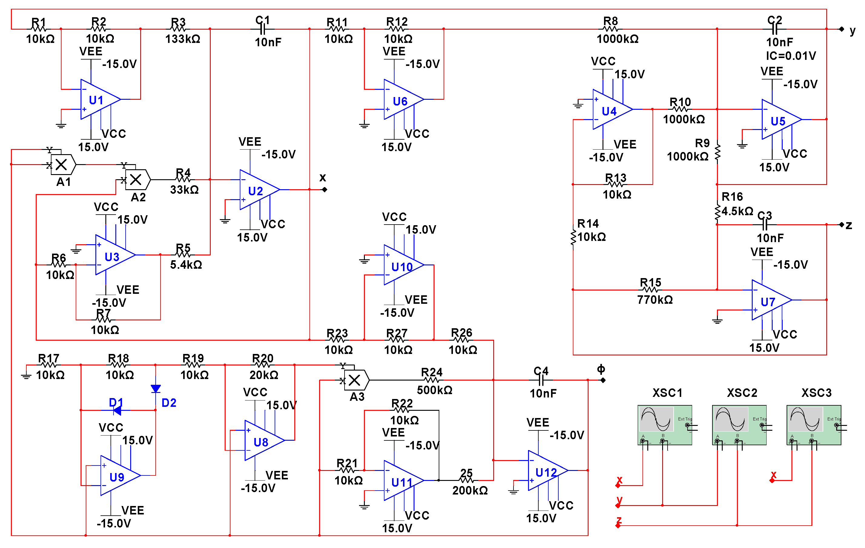
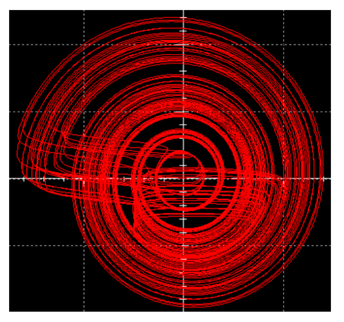
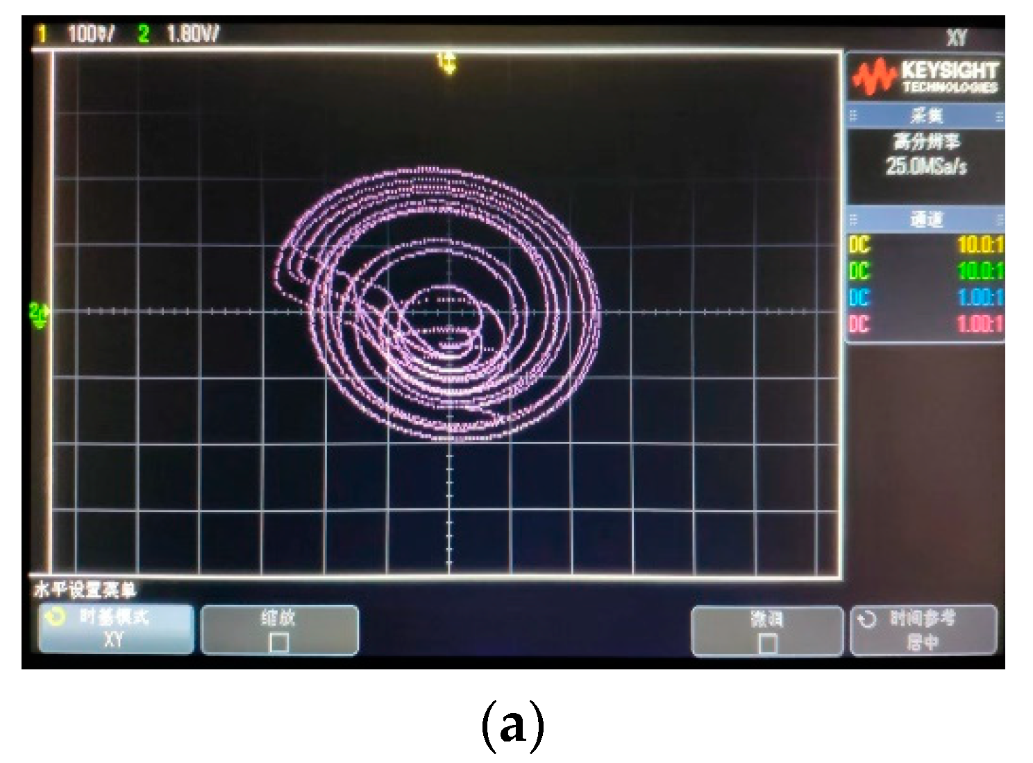
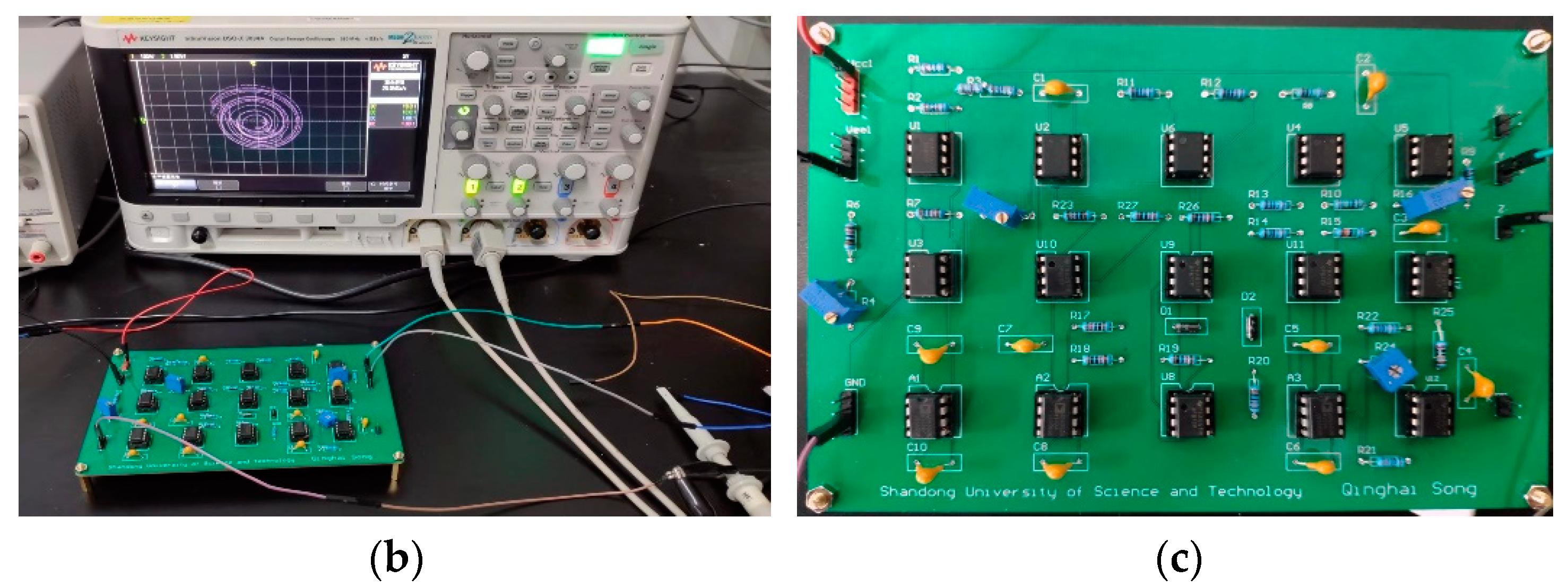
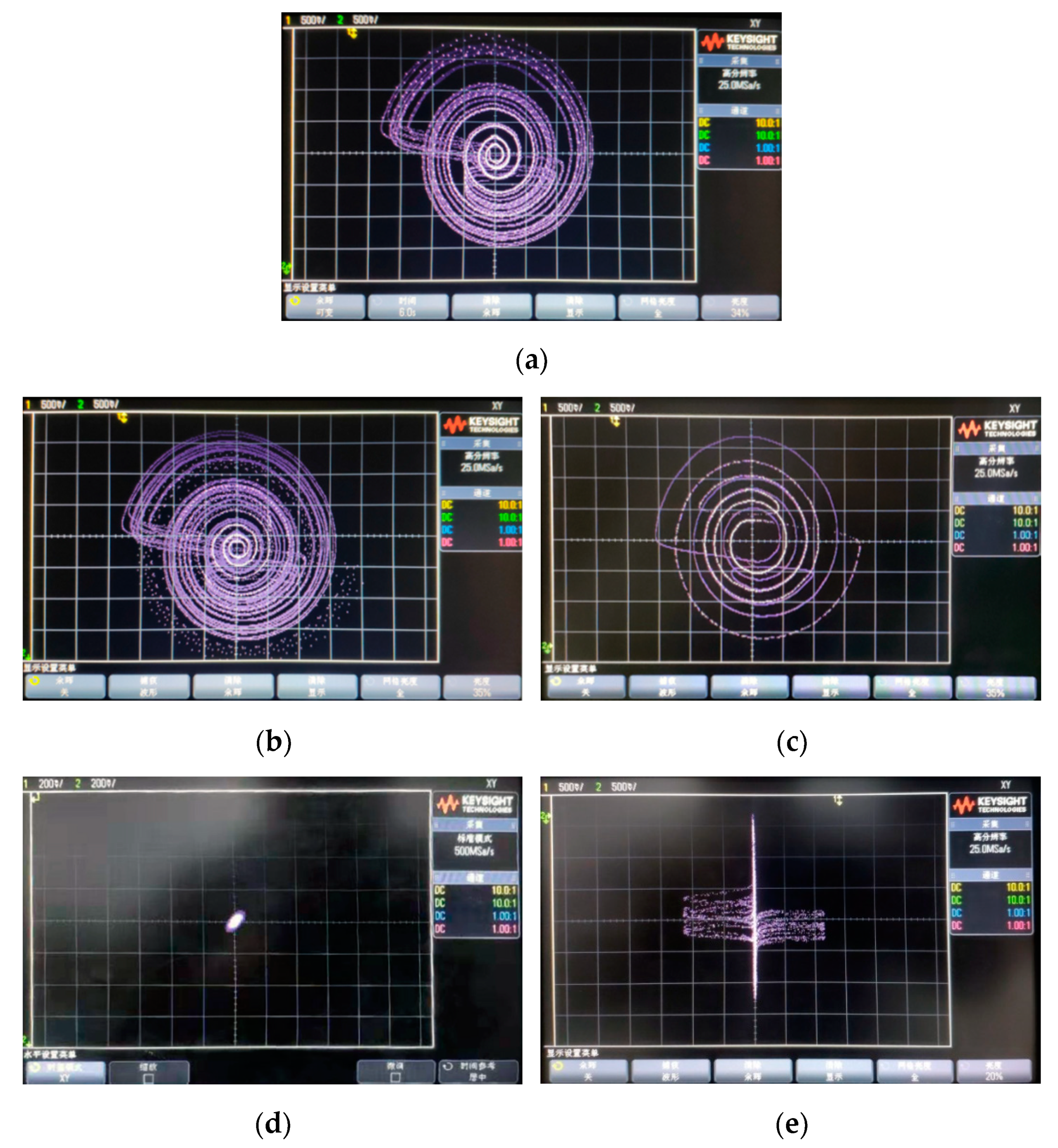
5. The Physical Realization of the Memristor-Based Chaotic System

In this section, an analog circuit of the memristor-based chaotic system is designed to verify the dynamic behaviors of the system, as shown in Figure 16.
The output voltages of the amplifier U2, U5, U7, and U12 are marked as v U 2 , v U 5 , v U 7 , and v U 12 , representing the state variables x(t), y(t), z(t), and φ(t) of the system. When the output voltages y(t) and x(t) pass through the inverters U1 and U3, the signals y(t) and x(t) are converted to −y(t) and −x(t). The signals φ(t) and x(t) are converted to φ2(t)x(t) through the multipliers A1 and A2. They are to be the input of the inverse integrator U2, then the first equation of the Equation (16) is obtained. The signals x(t) and z(t) are converted to −x(t) and −z(t) through the inverters U6 and U7. The second equation of Equation (16) is generated with the signals −x(t), y(t), and −z(t) at the input of the inverse integrator U5. With the inverse integrator U7, we can obtain the third equation of Equation (16). Through an absolute circuit consisting of two amplifiers U9 and U8, two diodes D1 and D2, and some resistors, signal φ(t) implements the absolute value operation, i.e., φ(t)→|φ(t)|. Then, the signal φ(t) is multiplied by the multiplier A3 to obtain φ(t)|φ(t)| as the input of inverse integrator U12. The final equation of the Equation (16) is obtained by the action of the amplifier U12. The dynamics of the circuit are described as
{ d X d T = R 2 C 1 R 1 R 3 Y 1 C 1 R 4 Φ 2 X + R 7 C 1 R 5 R 6 X d Y d T = R 12 C 2 R 8 R 11 X 1 C 2 R 9 Y + R 13 C 2 R 10 R 14 Z d Z d T = 1 C 3 R 16 Y 1 C 3 R 15 Z d Φ d T = 1 C 4 R 24 Φ | Φ | + R 22 C 4 R 21 R 25 Φ + R 27 C 4 R 23 R 26 X
In general, the larger the time scale transformation factor, the faster the time-domain orbit of the system runs and the denser the phase trajectory. Conversely, the smaller the time scale transformation factor, the slower the time domain orbit of the system runs and the sparser the phase trajectory. When the chaotic oscillator is designed, the time scale conversion can make up for the problem of the slow evolution of the time-domain of the system caused by excessive integration capacitance and can reduce the resistance value of the integration circuit. Accordingly, it is convenient for circuit debugging. The amplitude scale conversion is to constrain the range of system variables to the reference voltage (−15V, 15V) to prevent circuit saturation distortion. On the basis of Equation (16), the time scale transformation is performed first, and the inter-scale transformation factor K1 is set as 100, i.e., t = K1T = 100T.
Letting x = K2X, y = K2Y, z = K2Z, and Φ = K2φ, Equation (16) is transformed to
{ d x d t = R 2 K 1 C 1 R 1 R 3 y K 2 2 K 1 C 1 R 4 φ 2 x + R 7 K 1 C 1 R 5 R 6 x d y d t = R 12 K 1 C 2 R 8 R 11 x 1 K 1 C 2 R 9 y + R 13 K 1 C 2 R 10 R 14 z d z d t = 1 K 1 C 3 R 16 y 1 K 1 C 3 R 15 z d ϕ d t = K 2 K 1 C 4 R 24 φ | φ | + R 22 K 1 C 4 R 21 R 25 φ + R 27 K 1 C 4 R 23 R 26 x
where K2 = 2. Comparing Equation (14) and Equation (17), one has
a = R 2 K 1 C 1 R 1 R 3 = K 2 2 K 1 C 1 R 4 ,   b = 1 K 1 C 3 R 16 ,   c = 1 K 1 C 3 R 15 ,   a h a = R 7 K 1 C 1 R 5 R 6 ,  
R 12 K 1 C 2 R 8 R 11 = 1 K 1 C 2 R 9 = R 13 K 1 C 2 R 10 R 14 = K 2 K 1 C 4 R 24 = 1 ,   A = R 22 K 1 C 4 R 21 R 25 ,   B = R 27 K 1 C 4 R 23 R 26
when
  • C 1 = C 2 = C 3 = C 4 = 10 n f ,
  • R 1 = R 2 = R 6 = R 7 = R 11 = R 12 = R 13 = R 14 = R 18 = R 19 = R 20 = R 22 = R 23 = R 26 = R 27 = 10 k Ω ,
  • R 8 = R 9 = R 10 = 1000 k Ω , R 3 = 133 k Ω , R 4 = 33 k Ω , R 5 = 5.4 k Ω , R 15 = 770 k Ω , R 16 = 4.2 k Ω ,
  • R 24 = 500 k Ω , R 25 = 200 k Ω , R 21 = 20 k Ω .
The typical chaotic attractor of the system is obtained by Multisim experiment, as shown in Figure 17, which starts from the initial conditions (0, 0.001, 0, 0), and is consistent with those of the numerical simulation shown in Figure 6c.
Correspondingly the physical circuit of the memristor-based chaotic system is given to further verify the above-mentioned theoretical analysis. The experimental result of the circuit is obtained, as shown in Figure 18, where the multiplier is AD633JN and the operational amplifier is OP07CP. The typical chaotic attractor is displayed in Figure 18a, which is captured by the oscilloscope DSO-X3034A. The experimental result is also consistent with the numerical simulation in Figure 6c.

6. Implementation of the Chaotic System by DSP Technology

Although the memristive chaotic systems can be implemented by the analog circuits, the system characteristics that depend on the initial conditions are difficult to control. Moreover, chaotic artificial circuits cannot be used directly in digital encryption systems because random signal disturbances make the circuit output unstable.
Hence, the presented system was further discretized and realized on DSP (digital signal processing) platform, which makes the system controllable and stable enough to be used for chaotic encryption. There are usually three algorithms for the discretization and digitization of continuous chaotic systems: simple Euler algorithm, improved Euler algorithm, and Runge–Kutta algorithm. Each of these three algorithms has its advantages and disadvantages. The improved Euler algorithm and the Runge–Kutta algorithm have higher precision, but they occupy more resources. The simple Euler algorithm is accepted for DSP implementation as the simple Euler algorithm requires less resources and satisfies experimental requirements. The simple Euler algorithm comes from the following derivative:
d x d t = lim T 0 x ( t n + T ) x ( t n ) T x n + 1 x n T def _ _ x ( n + 1 ) x ( n ) T .
Substituting Equation (18) into Equation (14) yields
{ x ( n + 1 ) x ( n ) T = a [ y ( n ) x ( n ) + h x ( n ) φ 2 ( n ) x ( n ) ] y ( n + 1 ) y ( n ) T = x ( n ) y ( n ) + z ( n ) z ( n + 1 ) z ( n ) T = b y ( n ) c z ( n ) ϕ ( n + 1 ) φ ( n ) T = φ ( n ) | φ ( n ) | + A φ ( n ) + B x ( n )
Equation (19) is reset as
{ x ( n + 1 ) = a [ y ( n ) x ( n ) + h x ( n ) φ 2 ( n ) x ( n ) ]     T + x ( n ) y ( n + 1 ) = [ x ( n ) y ( n ) + z ( n ) ]     T + y ( n ) z ( n + 1 ) = [ b y ( n ) c z ( n ) ]     T + z ( n ) φ ( n + 1 ) = [ φ ( n ) | φ ( n ) | + A φ ( n ) + B x ( n ) ]     T + φ ( n )
where the parameters a, b, c, h, A, and B are set as in Table 1. The digital signal is obtained by solving Equation (20) in a digital signal processor, where the integration step T = 0.001 and the initial conditions are set as x(0) = 0, y(0) = 0.001, z(0) = 0, and φ(0) = 0. The experimental results of the memristor-based chaotic system by DSP technology are obtained, as shown in Figure 19, which shows the typical chaotic attractor on the (y, z) plane, the coexisting chaotic attractors, coexisting period-1 attractors on the (y, z) plane, the point attractors, and chaotic attractors on the (x, z) plane in Figure 19a–e, respectively. It can be seen from Figure 12b,c that the upper attractor was bright with the initial conditions (0, 0.001, 0, 0), and the lower attractor was dark with the initial condition (0, −0.001, 0, 0)). Additionally, Figure 19d,e confirms the existence of two states with switching. These are the point attractor and chaotic attractor, where the point attractor is obtained with the initial conditions (0, −0.2. 0, 0) and the chaotic attractor with the initial conditions (0, −0.1. 0, 0).
The results obtained by circuit experiment and DSP technology further verify the theoretical analysis of the system.

7. Conclusions

In this paper, a flux-controlled active memristor was presented and its emulator was designed, which showed its characteristic fingerprints. The hysteresis loops keep the symmetrical font “8” when the frequency is more than 300Hz, which indicates that the emulator is a suitable device to explore the circuit properties of the memristor. The memristor-based chaotic system was designed and a novel attractor was found in the system. The system not only has heterogeneous multistability, but also has the novel state-switching between point attractors and chaotic attractors with the change of the initial conditions. Furthermore, coexisting attractors and the transient chaotic attractor were implemented by the analog circuit and DSP technology, respectively, which verified the results of theoretical analysis. More rigorous theoretical analyses of the proposed memristor-based chaotic system will be further studied in the near future.

Author Contributions

Conceptualization, Q.S.; data curation, Y.L.; investigation, H.C.; methodology, H.C.; project administration, Y.L.; writing—original draft preparation, Q.S.; writing—review and editing, Q.S. and H.C.; All authors have read and agreed to the published version of the manuscript.

Funding

This work was supported by the Major Research Program of National Natural Science Foundation of China (91848206), the National Natural Science Foundation of China (grant nos. 61973200, 61801271), and the Shandong Provincial Natural Science Foundation of China (grant no. ZR2018ZC0436), the Taishan Scholar Project of Shandong Province of China.

Conflicts of Interest

The authors declare no conflict of interest.

References

  1. Chua, L. Memristor-the missing circuit element. IEEE Trans. Circuit Theory 1971, 18, 507–519. [Google Scholar] [CrossRef]
  2. Strukov, D.B.; Snider, G.S.; Stewart, D.R.; Williams, R.S. The missing memristor found. Nature 2008, 453, 80–83. [Google Scholar] [CrossRef] [PubMed]
  3. Corinto, F.; Gilli, M.; Forti, M. Flux-charge description of circuits with non-volatile switching memristor devices. IEEE Trans. Circuits Syst. II 2018, 65, 642–646. [Google Scholar] [CrossRef]
  4. Duan, S.K.; Hu, X.F.; Wang, L.D. Analog memristive memory with applications in audio signal processing. Sci. China Inform. Sci. 2014, 57, 1–15. [Google Scholar] [CrossRef]
  5. Liu, S.; Wang, Y.; Fardad, M. A memristor-based optimization framework for artificial intelligence applications. IEEE Circ. Syst. Mag. 2018, 18, 29–44. [Google Scholar] [CrossRef]
  6. Ge, J.; Zhang, S.; Liu, Z. Flexible artificial nociceptor using a biopolymer-based forming-free memristor. Nanoscale 2019, 11, 6591–6601. [Google Scholar] [CrossRef]
  7. Huang, X.; Fan, Y.; Jia, J.; Wang, Z.; Li, Y. Quasi-synchronization of fractional-order memristor-based neural networks with parameter mismatches. IET Control Theory Appl. 2017, 11, 2317–2327. [Google Scholar] [CrossRef]
  8. Yuan, F.; Huang, X.; Wang, Z. Nonlinear dynamics and chaos in a simplified memristor-based fractional-order neural network with discontinuous memductance function. Nonlinear Dynam. 2018, 93, 611–627. [Google Scholar]
  9. Li, Y.; Huang, X.; Song, Y. A new fourth-order memristive chaotic system and its generation. Int. J. Bifurc. Chaos 2015, 25, 1550151. [Google Scholar] [CrossRef]
  10. Chang, H.; Song, Q.; Li, Y. Unstable limit cycles and singular attractors in a two-dimensional memristor-based dynamic system. Entropy 2019, 21, 415. [Google Scholar] [CrossRef] [Green Version]
  11. Huang, X.; Jia, J.; Li, Y. Complex nonlinear dynamics in fractional and integer order memristor-based systems. Neurocomputing 2016, 218, 296–306. [Google Scholar] [CrossRef]
  12. Guo, M.; Xue, Y.; Gao, Z.; Zhang, Y.; Dou, G.; Li, Y. Dynamic analysis of a physical SBT memristor-based chaotic circuit. Int. J. Bifurc. Chaos 2018, 27, 1730047. [Google Scholar] [CrossRef]
  13. Wen, S.; Zeng, Z.; Huang, T. Fuzzy modeling and synchronization of different memristor-based chaotic circuits [J]. Phys. Lett. A 2013, 377, 2016–2021. [Google Scholar] [CrossRef]
  14. Itoh, M.; Chua, L.O. Memmristor osillators. Int. J. Bifurc. Chaos 2008, 18, 3183–3206. [Google Scholar] [CrossRef]
  15. Muthuswamy, B.; Kokate, P. Memristor-based chaotic circuits. IETE Tech. Rev. 2009, 26, 417. [Google Scholar] [CrossRef] [Green Version]
  16. Muthuswamy, B.; Chua, L.O. Simplest chaotic circuit. Int. J. Bifurc. Chaos 2010, 20, 1567–1580. [Google Scholar] [CrossRef]
  17. Chang, H.; Zhen, W.; Li, Y. Dynamic analysis of a bistable bi-local active memristor and its associated oscillator system. Int. J. Bifurc. Chaos 2018, 28, 1850105. [Google Scholar] [CrossRef]
  18. Nguomkam, N.A.; Kengne, J. A minimal three-term chaotic flow with coexisting routes to chaos, multiple solutions, and its analog circuit realization. Analog Integr. Circuits Signal Process. 2019, 101, 415–429. [Google Scholar] [CrossRef]
  19. Wang, G.; Yuan, F.; Chen, G. Coexisting multiple attractors and riddled basins of a memristive system. Chaos 2018, 28, 013125. [Google Scholar] [CrossRef]
  20. Zhou, C.; Li, Z.; Zeng, Y. A novel 3D fractional-order chaotic system with multifarious coexisting attractors. Int. J. Bifurc. Chaos 2019, 29, 1950004. [Google Scholar] [CrossRef]
  21. Chang, H.; Li, Y.; Yuan, F. Extreme multistability with hidden attractors in a simplest memristor-based circuit. Int. J. Bifurc. Chaos 2019, 29, 1950086. [Google Scholar] [CrossRef]
  22. Han, B.; Tao, J.; Kaibin, C. Memristor-based canonical Chua’s circuit: Extreme multistability in voltage-current domain and its controllability in flux-charge domain. Complexity 2018, 2018, 1–13. [Google Scholar]
  23. Buscarino, A.; Fortuna, L.; Frasca, M.; Valentina Gambuzza, L. A chaotic circuit based on Hewlett-Packard memristor. Chaos 2012, 22, 023136. [Google Scholar] [CrossRef] [PubMed]
  24. Wang, Z.; Abdolmohammadi, H.R.; Alsaadi, F.E. A new oscillator with infinite coexisting asymmetric attractors. Chaos Soliton. Fract. 2018, 110, 252–258. [Google Scholar] [CrossRef]
  25. Rajagopal, K.; Khalaf, A.J.M.; Wei, Z.; Pham, V.T.; Alsaedi, A.; Hayat, T. Hyperchaos and coexisting attractors in a memristor Van der Pol–Duffing oscillator. Int. J. Bifurc. Chaos 2019, 29, 1950067. [Google Scholar] [CrossRef]
  26. Alombah, N.H.; Fotsin, H.; Romanic, K.K. Coexistence of multiple attractors, metastable chaos and bursting oscillations in a multiscroll memristive chaotic circuit. Int. J. Bifurc. Chaos 2017, 27, 1750067. [Google Scholar] [CrossRef]
  27. Lai, Q.; Nestor, T.; Kengne, J. Coexisting attractors and circuit implementation of a new 4D chaotic system with two equilibria. Chaos Soliton. Fract. 2018, 107, 92–102. [Google Scholar] [CrossRef]
  28. Varshney, V.; Sabarathinam, S.; Prasad, A. Infinite number of hidden attractors in memristor-based autonomous Duffing oscillator. Int. J. Bifurc. Chaos 2018, 28, 1850013. [Google Scholar] [CrossRef]
  29. Wang, G.Y.; Shi, C.B.; Wang, X.W.; Yuan, F. Coexisting oscillation and extreme multistability for a memcapacitor based circuit. Math. Probl. Eng. 2017, 2017, 6504969. [Google Scholar] [CrossRef]
  30. Karthikeyan, R.; Jafari, S.; Karthikeyan, A. Hyperchaotic memcapacitor oscillator with infinite equilibria and coexisting attractors. Circ. Syst. Signal Pr. 2018, 37, 3702–3724. [Google Scholar]
  31. Tang, Y.X.; Abdul, J.M.K.; Rajagopal, K. A new nonlinear oscillator with infinite number of coexisting hidden and self-excited attractors. Chin. Phys. B 2018, 27, 040502. [Google Scholar] [CrossRef]
  32. Galias, Z. Numerical study of multiple attractors in the parallel inductor–capacitor–memristor circuit. Int. J. Bifurc. Chaos 2017, 27, 1730036. [Google Scholar] [CrossRef]
  33. Li, C.; Thio, W.J.C.; Lu, H.H.C.; Lu, T. A memristive chaotic oscillator with increasing amplitude and frequency. IEEE Access 2018, 6, 12945–12950. [Google Scholar] [CrossRef]
  34. Chua, L.O.; Kang, S.M. Memristive devices and systems. Proc. IEEE 1976, 64, 209–223. [Google Scholar] [CrossRef]
  35. Yuan, F.; Deng, Y.; Li, Y. The amplitude, frequency and parameter space boosting in a memristor-meminductor-based circuit. Nonlinear Dynam. 2019, 96, 389–405. [Google Scholar] [CrossRef]
Figure 1. Sketch map of the active memristor.
Electronics 09 00410 g001
Figure 2. Emulator of the active memristor (AM).
Electronics 09 00410 g002
Figure 3. Multisim simulations of pinched hysteresis loops of the AM emulator under an applied sinusoidal input with different frequencies: (a) f = 15 Hz, f = 3 0 Hz, and f = 40 Hz; (b) f = 80 Hz, f = 300 Hz, and f = 3000 Hz.
Electronics 09 00410 g003
Figure 4. Pinched hysteresis loops of the AM emulator under the sinusoidal input voltage with the frequency f = 650 Hz and different amplitudes: Um = 10 V, Um = 8 V, Um = 6 V, and Um = 4 V.
Electronics 09 00410 g004
Figure 5. Memristor-based chaotic circuit.
Electronics 09 00410 g005
Figure 6. Phase diagrams of the novel chaotic attractor of the AM-based oscillatory circuit: (a) on the (x, y, z) space; (b) on the (y, z, φ) space; (c) on the (y, z) plane; (d) on the (x, y) plane; (e) on the (y, φ) plane; (f) on the (x, φ) plane.
Electronics 09 00410 g006aElectronics 09 00410 g006b
Figure 7. (a) Poincaré mapping on the (y, z) plane; (b) the time domain waves of the states x, y, z, and φ.
Electronics 09 00410 g007
Figure 8. Projections of the attractors on the (y, z) plane with different initial conditions: (a) (0, 2, 0, 0); (b) (0, −2, 0, 0).
Electronics 09 00410 g008
Figure 9. Dynamics of the system with the parameter c (0.4, 1.5): (a) bifurcation diagram; (b) Lyapunov exponents.
Electronics 09 00410 g009
Figure 10. Phase portraits of the periodic and point attractors on the (x, y) plane with the different parameters: (a) period-1 attractor with c = 0.45; (b) period-2 attractor with c = 0.70; (c) period-4 attractor with c = 0.78; (d) a point attractor with c = 1.5.
Electronics 09 00410 g010aElectronics 09 00410 g010b
Figure 11. Dynamics of the system with the varying parameter a: (a) coexisting bifurcation diagram; (b) Lyapunov exponents.
Electronics 09 00410 g011
Figure 12. Evolution of coexisting attractors with the varying parameter a: (a) a = 7.38; (b) a = 7.5; (c) a = 8.0; (d) a = 8.2.
Electronics 09 00410 g012
Figure 13. The state-switching between point attractors and chaotic attractors with the varying component y(0).
Electronics 09 00410 g013
Figure 14. Dynamics of the system with y(0) (−3, 3): (a) bifurcation diagram; (b) Lyapunov exponents.
Electronics 09 00410 g014
Figure 15. The transient phenomenon of the system: (a) the time-domain wave of the state y; (b) the attractor with the time duration t = 0–23; (c) the attractor with the time duration t = 23–30.
Electronics 09 00410 g015
Figure 16. Circuit diagrams of the system.
Electronics 09 00410 g016
Figure 17. The typical chaotic attractor of the memristive chaotic system by Multisim.
Electronics 09 00410 g017
Figure 18. The experimental results of the memristive chaotic system from the physical circuit: (a) the typical chaotic attractor from the oscilloscope; (b) experimental platform; (c) the corresponding circuit board.
Electronics 09 00410 g018aElectronics 09 00410 g018b
Figure 19. Digital signal processing (DSP) implemental results of the chaotic system: (a) the typical chaotic attractor; (b) the coexisting chaotic attractor; (c) the coexisting period-1 attractor; (d) the point attractor; (e) the typical chaotic attractor.
Electronics 09 00410 g019
Table 1. Parameter values of typical attractors of the memristor-based chaotic system.
ParametersabchAB
Values7.51991.3255100

