Article

Dynamic Surface Backstepping Control for Voltage Source Converter-High Voltage Direct Current Transmission Grid Side Converter Systems

1
School of Automation, Qingdao University, Qingdao 266071, China
2
College of Computer Science and Technology, Qingdao University, Qingdao 266071, China
*
Author to whom correspondence should be addressed.
Electronics 2020, 9(2), 333; https://doi.org/10.3390/electronics9020333
Submission received: 6 January 2020 / Revised: 9 February 2020 / Accepted: 11 February 2020 / Published: 15 February 2020
(This article belongs to the Section Systems & Control Engineering)

Abstract

:
This paper studies the coordination control of active and reactive power of the voltage source converter-high voltage direct current transmission (VSC-HVDC) grid side converter. Firstly, the high-order VSC-HVDC converter system is decomposed into three subsystems by using the backstepping control method, and the control laws are designed for each subsystem to realize the control of VSC-HVDC converter systems. Secondly, the dynamic surface control method is used to deal with the problem of “explosion of complexity” in the traditional backstepping control method. Finally, the simulation results demonstrate that the VSC-HVDC converter systems can provide a certain capacity of reactive power compensation under the proposed method in this paper. In addition, the control method proposed in this paper does not require the information of the second derivative of active power and reactive power.

1. Introduction

The offshore wind power generation has developed rapidly with the advantages of low cost and environmental protection [1,2,3,4]. At the same time, the scale of offshore wind farms which are far from land was increasing. At present, the technology of wind power generation is relatively mature. However, the offshore power needs to be delivered to land before it can be used. Thus, the long distance transmission technology of electricity is the key technology to promote the further development of the offshore wind farms.
The insulated gate bipolar transistors (IGBT) has the advantages of large safe working area, current shock resistance, and high switching speed [5,6,7,8,9]. Therefore, the voltage source converter-high voltage direct current transmission (VSC-HVDC) based on IGBT switch technology [10,11,12,13] has been widely used in the offshore wind power grid connected technology. However, the VSC-HVDC converter system is a high-order system. In recent years, scholars have applied sliding mode control [14,15,16,17,18], backstepping control [19,20,21,22,23], and some other control methods [24,25,26,27,28,29,30] to the study of electric power systems and high-order systems. The proportional-integral (PI) double closed-loop control method has been studied in [31,32], and Ref. [31] realized the decoupling control of active power and reactive power. However, the conventional PI regulator based on linear system theory can not guarantee the good dynamic performance of the control systems. In [33,34], the robust control method is introduced to the control of HVDC, which can suppress the control error caused by inaccurate parameters and disturbance to some extent. Fuzzy control technology is introduced in [35,36], but the calculation of the control method is large and the calculation process is complex. In [37], the backstepping control method is applied to solve the complex problem of controller design in higher-order systems, and it is proved that the controller designed by the backstepping method can improve the transient stability of the systems. The control methods of fixed active power and reactive power are applied to the control of VSC transmission systems in [38], which gives good control effect. In practical power grid engineering, a great number of the large capacity power grid systems use LCL filters instead of pure inductance filter to improve the quality of power grid connection. In [39], the designed method of filter parameters is studied, and the design process of LCL filters is given by the research results. However, LCL filters exist the resonance peak, which may lead the control system to fail to maintain stability. Considering the existence of the resonance peak in LCL filters, an active damping control method is proposed in [40,41] to overcome the problem caused by the resonance peak.
As one of the most effective approaches to control the high-order systems, the backstepping control method is applied to the power control of VSC-HVDC converter systems in [22], where the high-order system is handled by the backstepping control method. Compared with the traditional double closed loop vector control method, the convergence speed of VSC-HVDC converter systems is faster under the backstepping control method [22]. However, there are two main shortcomings in the traditional backstepping control method. One is the problem of “explosion of complexity” existing in the traditional backstepping control method, which is caused by the repeated derivation of virtual control function.The problem of “explosion of complexity” greatly increases the amount of calculation in the process of the backstepping controller design. Nevertheless, how to solve the problem of “explosion of complexity” was not considered in [19,22]. It is of practical significance to try to solve the problem above. According to [22], it can be seen that the traditional backstepping control can not achieve the coordination control of active and reactive power of VSC-HVDC converter systems without the second derivative information of expected active and reactive power. How to overcome the above two shortcomings and realize the coordinated control of active power and reactive power of VSC-HVDC converter systems is a challenging problem.
Taking the above analysis as motivation, a dynamic surface control method via backstepping control for voltage source converter-high voltage direct current transmission converter systems is proposed in this paper. Compared with the method of series damping resistance of filter capacitor branch [42,43], the control method in this paper can avoid the additional loss of damping resistance effectively. Considering the control method in [44], the control method in our work does not require to measure the current value of the filter capacitor, thereby reducing the number of sensors used. From another perspective, in our work, the backstepping control method is utilized to decompose the high-order VSC-HVDC converter systems into three second-order subsystems, and the control laws are designed for each subsystem to realize the coordinated control of active and reactive power of the overall system. Moreover, the dynamic surface control method [26] is used to overcome the two main shortcomings in the traditional backstepping control method. Compared with the traditional control method, the control strategy proposed in our work mainly has the following novelties and advantages:
(1) In this paper, at each step of the backstepping, the dynamic surface control method is introduced to solve the problem of “explosion of complexity” in [22], which can greatly improve the efficiency of the power regulation.
(2) Different from the traditional backstepping control method, the method proposed in this paper can achieve the power coordination control of VSC-HVDC converter systems without the information of the second derivative of active power and reactive power.
Simulation results illustrate the validity of the proposed design scheme.

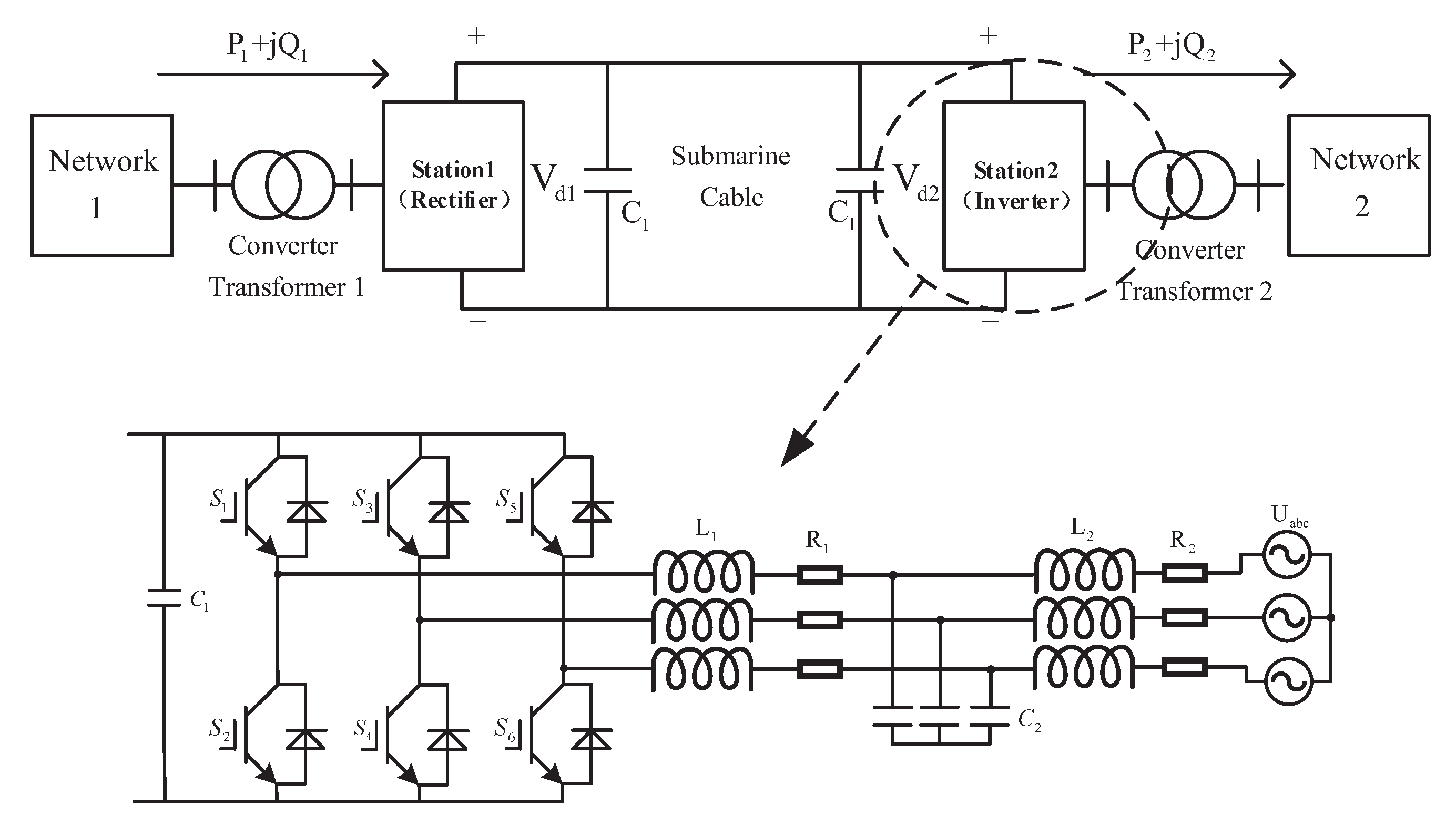
2. Mathematical Model and Preliminaries

The structure of VSC-HVDC transmission systems is shown in Figure 1. The VSC-HVDC transmission system includes transformer, converter station, alternating current (AC) network, etc. Network 1 and Network 2 are independent AC power grid systems. Network 1 is the offshore wind farm side, and Network 2 is the grid side. This paper takes VSC-HVDC grid side converter as the research object to study. The power loop is regulated by the PI control method and the current loop is controlled by dynamic surface control method via backstepping.
Consider the mathematical model of grid side converter in the VSC-HVDC system [22] as follows:
L 2 d i 2 d d t = E sd R 2 i 2 d u c d + ω L 2 i 2 q L 2 d i 2 q d t = R 2 i 2 q u c q ω L 2 i 2 d C 2 d u cd d t = ( i 2 d i 1 d ) + ω C 2 u cq C 2 d u cq d t = ( i 2 q i 1 q ) + ω C 2 u cd L 1 d i 1 d d t = u cd R 1 i 1 d u d + ω L 1 i 1 q L 1 d i 1 q d t = u cq R 1 i 1 q u q + ω L 1 i 1 d
where u cd and u cq are the d–q axis components of the three phase filter capacitor voltage, u d and u q are the d–q axis components of the AC side voltage of the converter, i 1 d and i 1 q are the d–q axis components of the current on AC side of converter, i 2 d and i 2 q are d–q axis components of three phase current on the grid side, ω is the angular frequency of the grid, C 2 is the filter capacitor, L 1 and L 2 are the filter reactance, R 1 is the equivalent resistance of the DC side capacitor, R 2 is the equivalent resistance of the filter capacitor, and E sd is the d-axis component of the grid voltage.
Redefine the following variables: x 1 = i 2 d , x 2 = i 2 q , x 3 = u cd , x 4 = u cq , x 5 = i 1 d , x 6 = i 1 q , b 2 = R 2 / L 2 , b 1 = R 1 / L 1 , T 1 = E sd / L 2 . Based on the above definition, the mathematical model of VSC-HVDC grid side converter can be transformed into
x ˙ 1 = b 2 x 1 x 2 / L 2 + ω x 2 + T 1 x ˙ 2 = b 2 x 2 x 4 / L 2 ω x 1 x ˙ 3 = x 1 x 5 / C 2 + ω x 4 x ˙ 4 = x 2 x 6 / C 2 + ω x 3 x ˙ 5 = b 1 x 5 + x 3 / L 1 + ω x 6 u d / L 1 x ˙ 6 = b 1 x 6 + x 4 / L 1 + ω x 5 u q / L 1 .
Remark 1.
Both station 1 and station 2 in Figure 1 adopt the voltage source converter; that is to say, the structure of VSC-HVDC system is symmetrical. Therefore, this paper takes the grid side converter as the research object.

3. Dynamic Surface Backstepping Controller Design

Define the following error variables:
z 1 = x 1 x 1 d , z 2 = x 2 x 2 d , z 3 = x 3 α 3 d , z 4 = x 4 α 4 d , z 5 = x 5 α 5 d , z 6 = x 6 α 6 d ,
where x 1 d is the expected signal of x 1 , and x 2 d is the expected signal of x 2 . The working principle of the dynamic surface filter is shown in Figure 2. α i d i = 3 , 4 , 5 , 6 is the output of dynamic surface filters. The purpose of introducing dynamic surface filter is to generate variable α i d and α ˙ i d . | α i d α i | is a sufficiently small value.
Remark 2.
The dynamic surface filter (DSF) is a first-order low-pass filter. The structure of the DSF is given in Equation (6) and Equation (11). Compared with the control method in [22], the DSF is introduced to solve the two main shortcomings in backstepping. One is the problem of “explosion of complexity”, which exists in backstepping, and another is that the traditional backstepping control method requires the information of high order derivative of the expected signal.
Step 1: Choose V 1 = 1 2 z 1 2 + 1 2 z 2 2 as the Lyapunov function of the first subsystem. Then,
V ˙ 1 = z 1 z ˙ 1 + z 2 z ˙ 2 = z 1 ( x ˙ 1 x ˙ 1 d ) + z 2 ( x ˙ 2 x ˙ 2 d ) = z 1 ( b 2 x 1 α 3 d α 3 L 2 z 3 L 2 α 3 L 2 + ω x 2 + T 1 x ˙ 1 d ) + z 2 ( b 2 x 2 α 4 d α 4 L 2 z 4 L 2 α 4 L 2 + ω x 1 x ˙ 2 d ) .
In this paper, the d-axis component of the grid voltage has a bound; therefore, T 1 is a bounded value and satisfies T 1 d . It can be obtained from the Young’s inequality:
z 1 T 1 1 2 ε 1 2 z 1 2 + 1 2 ε 1 2 d 2 .
Then, the new variables α 3 d and α 4 d are introduced. Let α 3 and α 4 pass through the dynamic surface filter with the time constant ϵ 3 and ϵ 4 , respectively; the output signals of the dynamic surface filter are α 3 d and α 4 d :
ϵ i α ˙ i d + α i d = α i , α i d ( 0 ) = α i ( 0 ) , ( i = 3 , 4 ) .
Substituting Inequality (5) into Equation (4), the following inequality can be obtained:
V ˙ 1 z 1 ( b 2 x 1 α 3 d α 3 L 2 z 3 L 2 α 3 L 2 + ω x 2 x ˙ 1 d + 1 2 ε 1 2 z 1 ) + z 2 ( b 2 x 2 α 4 d α 4 L 2 z 4 L 2 α 4 L 2 + ω x 1 x ˙ 2 d ) + 1 2 ε 1 2 d 2 .
The virtual control laws of the first subsystem are selected as
α 3 = L 2 ( k 1 z 1 b 2 x 1 + ω x 2 x ˙ 1 d ) α 4 = L 2 ( k 2 z 2 b 2 x 2 ω x 1 x ˙ 2 d )
where k 1 = k ¯ + 1 2 ε 1 2 , k ¯ > 0 and k 2 > 0 . Substituting Equation (8) into Inequality (7) results in
V ˙ 1 k 1 z 1 2 k 2 z 2 2 z 1 ( α 3 d α 3 ) L 2 z 2 ( α 4 d α 4 ) L 2 z 1 z 3 L 2 z 2 z 4 L 2 + 1 2 ε 1 2 d 2 .
Step 2: For the second subsystem, choose the Lyapunov function candidate as V 2 = V 1 + 1 2 z 3 2 + 1 2 z 4 2 . Taking the derivative of V 2 yields
V ˙ 2 = V ˙ 1 + z 3 z ˙ 3 + z 4 z ˙ 4 = V ˙ 1 + z 3 ( x 1 C 2 x 5 C 2 + ω x 4 α ˙ 3 d ) + z 4 ( x 2 C 2 x 6 C 2 ω x 3 α ˙ 4 d ) .
Then, the new variables α 5 d and α 6 d are introduced. Let α 5 and α 6 pass through the dynamic surface filter with the time constant ϵ 5 and ϵ 6 , respectively, the output signals of the dynamic surface filter are α 5 d and α 6 d :
ϵ i α ˙ i d + α i d = α i , α i d ( 0 ) = α i ( 0 ) , ( i = 5 , 6 ) .
Substituting Equation (6) into Equation (10) results in
V ˙ 2 = V ˙ 1 + z 3 ( x 2 C 2 z 1 L 2 α 5 d α 5 C 2 z 5 C 2 α 5 C 2 + ω x 4 + α 3 d α 3 ϵ 3 ) + z 4 ( x 1 C 2 z 2 L 2 z 6 C 2 α 6 d α 6 C 2 α 6 C 2 ω x 3 + α 4 d α 4 ϵ 4 ) .
The virtual control laws of the second subsystem are selected as
α 5 = C 2 ( k 3 z 3 + x 1 C 2 z 1 L 2 + ω x 4 ) α 6 = C 2 ( k 4 z 4 + x 2 C 2 z 2 L 2 ω x 3 )
where k 3 > 0 and k 4 > 0 . Substituting Equation (13) into Equation (12) gives
V ˙ 2 k 1 z 1 2 k 2 z 2 2 k 3 z 3 2 k 4 z 4 2 z 1 ( α 3 d α 3 ) L 2 z 2 ( α 4 d α 4 ) L 2 z 3 ( α 5 d α 5 ) C 2 z 4 ( α 6 d α 6 ) C 2 + z 3 ( α 3 d α 3 ) ϵ 3 + z 4 ( α 4 d α 4 ) ϵ 4 z 3 z 5 C 2 z 4 z 6 C 2 + 1 2 ε 1 2 d 2 .
Step 3: Choose V 3 = V 2 + 1 2 z 5 2 + 1 2 z 6 2 as the Lyapunov function of the third subsystem. Taking the derivative of V 3 yields
V ˙ 3 = V ˙ 2 + z 5 z ˙ 5 + z 6 z ˙ 6 = i = 1 4 k i z i 2 z 1 ( α 3 d α 3 ) L 2 z 4 ( α 6 d α 6 ) C 2 z 2 ( α 4 d α 4 ) L 2 z 3 ( α 5 d α 5 ) C 2 + 1 2 ε 1 2 d 2 + z 3 ( α 3 d α 3 ) ϵ 3 + z 4 ( α 4 d α 4 ) ϵ 4 + z 5 ( b 1 x 5 + x 3 / L 1 + ω x 6 u d / L 1 + α 5 d α 5 ϵ 5 ) + z 6 ( b 1 x 6 + x 4 / L 1 + ω x 5 u q / L 1 + α 6 d α 6 ϵ 6 ) z 3 z 5 C 2 z 4 z 6 C 2 .
The actual control laws of the first subsystem are selected as
u d = L 1 ( k 5 z 5 b 1 x 5 + x 3 L 1 + ω x 6 z 3 C 2 ) u q = L 1 ( k 6 z 6 b 1 x 6 + x 4 L 1 ω x 5 z 4 C 2 ) ,
where k 5 > 0 and k 6 > 0 . The stability proof part is given in Appendix A.
The structure of the controller in our work is given by Equation (16). Compared with the controller designed by the traditional backstepping control method, the structure of the controller under the dynamic surface backstepping control method is simpler. The controller designed by the traditional backstepping control method [22] is shown as follows:
u d = k 5 z 5 + ω x 6 + x 3 / L 1 b 1 x 5 + z 3 / C 2 C 2 ( k 3 z 3 L 2 ( k 1 ( x ¨ 1 r e f ( b 2 x ˙ 1 x ˙ 2 / L 2 + ω x ˙ 2 + T ˙ 1 ) ) x ¨ 1 r e f b 2 ( T ˙ 1 b 2 x ˙ 1 x ˙ 2 / L 2 + ω x ˙ 2 ) + ω ( b 2 x ˙ 2 x ˙ 4 / L 2 ω x ˙ 1 ) + T ¨ 1 ) + ω x 4 + ( x ˙ 1 r e f ( b 2 x 1 x 2 / L 2 + ω x 2 + T 1 ) ) / L 2 ) + b 2 x 1 + x 2 / L 2 ω x 2 T 1 , u q = k 6 z 6 ω x 5 + x 4 / L 1 b 1 x 6 + z 4 / C 2 C 2 ( k 4 ( L 2 ( k 2 z ˙ 2 x ¨ 2 r e f ω x ˙ 1 b 2 x ˙ 2 ) 1 C 2 ( x 1 x 5 ) + ω x 3 ) + x ˙ 2 L 2 ( k 2 ( x ¨ 2 r e f + d b 2 x 2 d t + d ω x 1 d t + d x 4 / L 2 d t ) x ¨ 2 r e f + b 2 d b 2 x 2 d t + b 2 d x 4 / L 2 d t + b 2 d ω x 1 d t ω x ¨ 1 ) ω x ˙ 3 + z ˙ 2 / L 2 ) .
Remark 3.
By comparing Equation (17) with Equation (16), it should be emphasized that the structure of the controller designed in our work is simpler than that under the backstepping method. Additionally, compared with [22], the controller designed in this paper does not require the information of the second derivative of active and reactive power, which makes the control method in our work more suitable for practical application.
In this paper, the active power and the reactive power are taken as the control object, and the principle of the control system of the grid side converter is shown in Figure 3. Compared with the control method proposed in [44], the control method in this paper does not need to measure the current value of the filter capacitor, which effectively improves the calculated efficiency of the control systems.
Remark 4.
The output of dynamic surface filter can approximate the derivative of virtual control function. Thus, the problem of “explosion of complexity” caused by repeated derivation of virtual control law in backstepping control is solved. The problem of “explosion of complexity” in [22] is described in Equation (17).

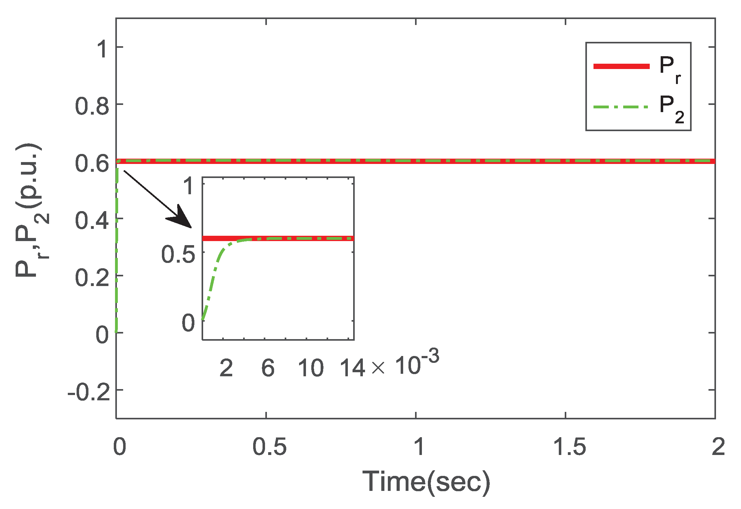
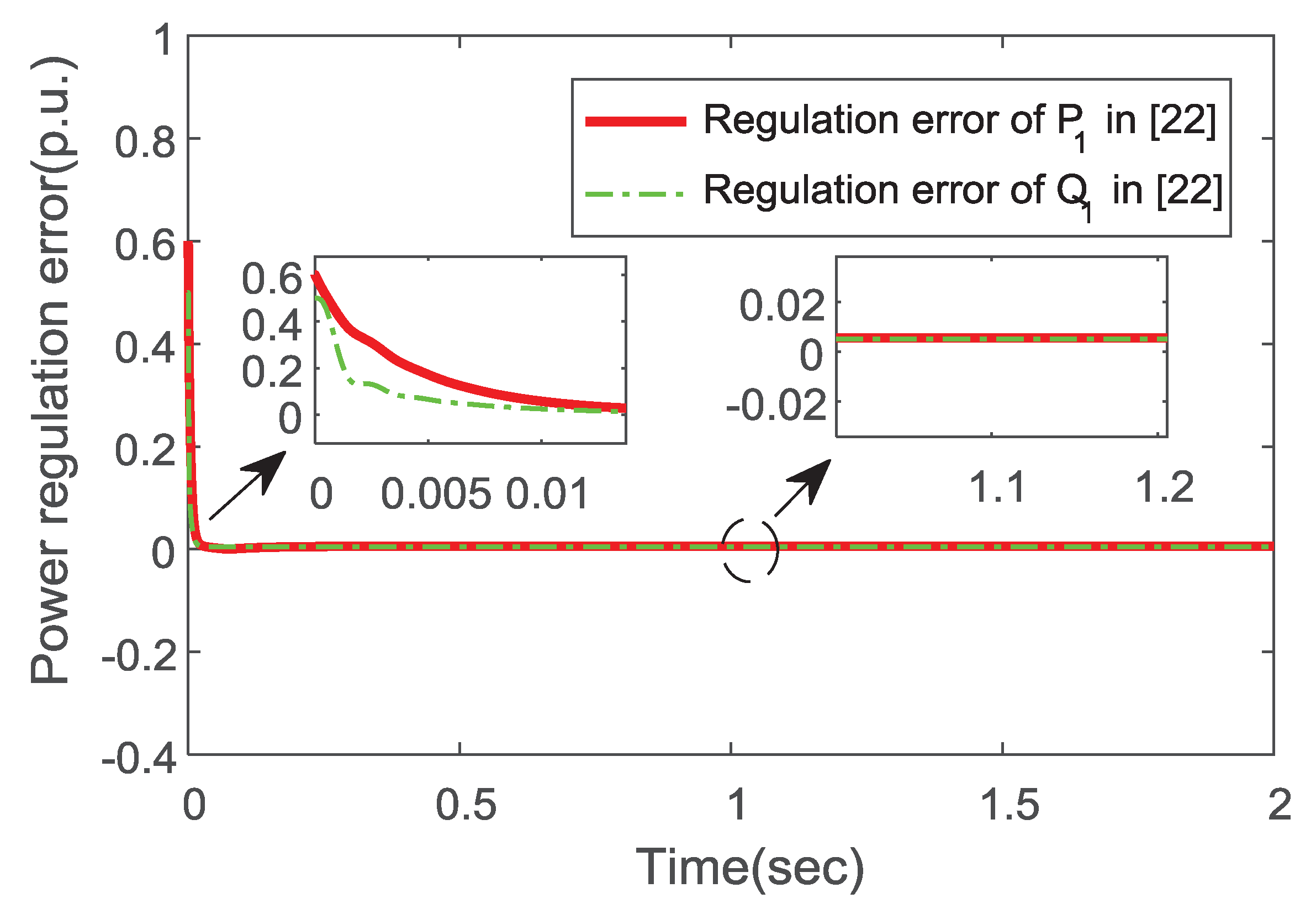
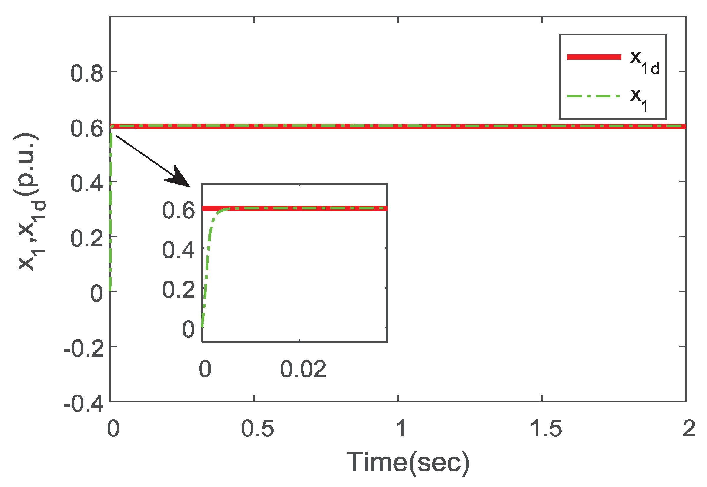
4. Simulation Analysis

In this part, the simulation model of the VSC-HVDC converter systems is built in the MATLAB environment, and the control system is implemented in the continuous-time domain to verify the feasibility and validity of the proposed control method in our work. The designed system capacity is 20 MVA, and adopts the space vector PWM modulation mode. Then, the parameters are standardized. The values of controller parameters and system model parameters are given in Table 1.
The parameters of PI regulation are selected as: K p 1 = K p 2 = 900 , K i 1 = K i 2 = 1000 . Choose the following expected signals as active and reactive power set points:
P r = 0.6 p . u . , Q r = 0.5 p . u .
Figure 4 shows the response curve of active power under the control method in this paper, where P r is the given value of active power, and P 2 is the active power of the VSC-HVDC converter system under the control method in this paper. Figure 4 shows that the controller designed in this paper can realize fast and accurate regulation of active power. Similarly, Figure 5 presents the response curve of reactive power. The simulation results show that the dynamic surface backstepping control method can regulate the active and reactive power rapidly and precisely. Note that Figure 6 shows the power regulation error curve of the VSC-HVDC converter systems under the control method presented in this paper. The simulation results show that the power regulation error converges to a small neighborhood around the origin at 0.004 s. Compared with the double closed-loop vector control method in [45], the PI regulator of current loop is not needed in our work, which ensures that the control method in this paper has a good dynamic response.
Remark 5.
From Figure 4 and Figure 5, it can be observed that the control method proposed in this paper can achieve fast and accurate regulation of power compared with the control method proposed in [22]. Moreover, the VSC-HVDC converter systems can provide a certain reactive power while providing active power under the proposed method in our work.
Figure 7 and Figure 8 show the active power and reactive power curves under the traditional backstepping control method, where P 1 and Q 1 are response curves of active power and reactive power. Figure 9 shows the power regulation error curve of the VSC-HVDC converter system under the control method in [22]. As can be seen from Figure 4, Figure 5, Figure 6, Figure 7, Figure 8 and Figure 9, the convergence speed of power regulation error is faster under the dynamic surface control method via backstepping. The above results are mainly due to the introduction of dynamic surface control method in our work, which can solve the problem of “explosion of complexity” in the traditional backstepping control, so that the convergence speed of the power regulation error is faster. In the process of simulation, it is difficult to adjust the controller parameters under the PI control method [30]. Compared with the PI control method, one of the advantages in our work is that the parameter adjustment of the controller is simple, and the regulation of parameter adjustment is shown in Appendix A.
Figure 10 and Figure 11 are the tracking curves of x 1 and x 2 in the control of current loop. The simulation results show that x 1 and x 2 can track the desired signal quickly and accurately. It can be seen from Figure 12 that the control errors of x 1 and x 2 converge to a small neighborhood around the origin at 0.004 s. Compared with the control method in [44], the control method in our work does not need to measure the current of the filter capacitor, thus reducing the calculation of the controller. Therefore, the simulation results show that x 1 and x 2 can track the expected singal quickly.
Verify that the proposed control method in this paper is still valid when the second derivative of active and reactive power does not exist. Then, reselect the following expected signals as the active and reactive power set points, where the second derivative information of the set point cannot be calculated:
P r = 0.2 sin ( 10 t 4 / 3 ) + 0.53 p . u . , Q r = 0.2 sin ( 10 t 4 / 3 ) + 0.26 p . u .
Note that Figure 13 shows the active power curve under the dynamic surface control method via backstepping. Figure 14 shows the active power curve in this paper and Figure 15 shows the power error curve of VSC-HVDC converter systems in this paper.
Remark 6.
According to Equation (17), the information of the second derivative of active power and reactive power is needed under the traditional backstepping control method. Figure 13, Figure 14 and Figure 15 note that the proposed method in this paper is still effective without the information of the second derivative of active power and reactive power. Therefore, the method proposed in this paper has a wider range of applications.

5. Conclusions

In this paper, a dynamic surface control method via backstepping control is proposed to solve the problem of coordinated control of active power and reactive power for VSC-HVDC converter systems. In the proposed approach, the backstepping control method is introduced to handle the high-order VSC-HVDC converter systems. The dynamic surface control method can overcome the two main shortcomings of traditional backstepping control method. Furthermore, the proposed method can also guarantee that the power regulation error converges into a small neighborhood around the origin and that the VSC-HVDC system can provide a certain capacity of reactive power. The simulation results show that the dynamic response in this paper is obviously better than that in [22]. Future research will focus on how to deal with the influence of dynamic surface filter error.

Author Contributions

Conceptualization, C.H. and J.Y.; methodology, C.H. and L.Z.; software, Y.M.; validation, J.Y., C.H. and Y.M.; formal analysis, C.H.; investigation, J.Y.; resources, J.Y. and L.Z.; data curation, Y.M.; writing–original draft preparation, C.H. and J.Y.; writing–review and editing, C.H. and J.Y.; visualization, J.Y.; supervision, Y.M.; project administration, J.Y.; funding acquisition, J.Y., L.Z. and Y.M. All authors have read and agreed to the published version of the manuscript.

Funding

This work was supported by the National Key Research and the Development Plan (2017YFB1303503), the National Natural Science Foundation of China (61973179,61573204, 61501276), and the Taishan Scholar Special Project Found (TSQN20161026).

Conflicts of Interest

The authors declare no conflict of interest.

Appendix A. Stability Proof

Substituting Equation (16) into Equation (15) results in
V ˙ 3 i = 1 6 k i z i 2 z 1 ( α 3 d α 3 ) L 2 z 2 ( α 4 d α 4 ) L 2 z 3 ( α 5 d α 5 ) C 2 z 4 ( α 6 d α 6 ) C 2 + z 3 ( α 3 d α 3 ) ϵ 3 + z 4 ( α 4 d α 4 ) ϵ 4 + z 5 ( α 5 d α 5 ) ϵ 5 + z 6 ( α 6 d α 6 ) ϵ 6 + 1 2 ε 1 2 d 2 .
Define the errors of dynamic surface filter as
y i = α i d α i , ( i = 3 , 4 , 5 , 6 ) .
Then, from Equation (A2), the following equations can be obtained:
y ˙ i = α i d α i ϵ i α ˙ i = y i ϵ i + D i , ( i = 3 , 4 , 5 , 6 ) ,
where D 3 = α ˙ 3 , D 4 = α ˙ 4 , D 5 = α ˙ 5 , D 6 = α ˙ 6 .
By [25], | D i | has a maximum value D i M on compact Ω i ( i = 3 , 4 , 5 , 6 ) . Therefore, | D i | D i M . It can be obtained from Young’s inequality
y i y ˙ i y i 2 / ϵ i + D i M y i y i 2 / ϵ i + 1 2 τ D i M 2 y i 2 + τ 2 ,
where τ > 0 and i = 3 , 4 , 5 , 6 . By Young’s inequality, the following inequalities can be obtained:
y 3 z 1 L 2 y 3 2 / 4 L 2 + z 1 2 / L 2 , y 4 z 2 L 2 y 4 2 / 4 L 2 + z 2 2 / L 2 , y 5 z 3 C 2 y 5 2 / 4 C 2 + z 3 2 / C 2 , y 6 z 4 C 2 y 6 2 / 4 C 2 + z 4 2 / C 2 , y i z i ϵ i y i 2 / 4 ϵ i + z i 2 / ϵ i ,
where i = 3 , 4 , 5 , 6 . In order to prove the stability of the control system, choose the Lyapunov function as V = V 3 + 1 2 y 3 2 + 1 2 y 4 2 + 1 2 y 5 2 + 1 2 y 6 2 , then
V ˙ i = 1 6 k i z i 2 z 1 L 2 y 3 z 2 L 2 y 4 z 3 C 2 y 5 z 4 C 2 y 6 + i = 3 6 z i ϵ i y i + i = 3 6 y i y ˙ i + 1 2 ε 1 2 d 2 .
Substituting Inequalities (A4) and (A5) into Inequality (A6) results in
V ˙ i = 1 6 k i z i 2 + y 3 2 4 L 2 + z 1 2 L 2 + y 4 2 4 L 2 + z 2 2 4 L 2 + y 5 2 4 C 2 + z 3 2 C 2 + y 6 2 4 C 2 + z 4 2 C 2 + y 3 2 4 ϵ 3 + z 3 2 ϵ 3 + y 4 2 4 ϵ 4 + z 4 2 ϵ 4 + y 5 2 4 ϵ 5 + z 5 2 ϵ 5 + y 6 2 4 ϵ 6 + z 6 2 ϵ 6 y 3 2 ϵ 3 + 1 2 τ D 3 M 2 y 3 2 + τ 2 y 4 2 ϵ 4 + 1 2 τ D 4 M 2 y 4 2 y 5 2 ϵ 5 + 1 2 τ D 5 M 2 y 5 2 + τ 2 y 6 2 ϵ 6 + 1 2 τ D 6 M 2 y 6 2 + τ 2 + τ 2 + 1 2 ε 1 2 d 2 a V + b
where a = min { 2 ( k 1 1 L 2 ) , 2 ( k 2 1 L 2 ) , 2 ( k 3 1 C 2 1 ϵ 3 ) , 2 ( k 4 1 C 2 1 ϵ 4 ) , 2 ( k 5 1 ϵ 5 ) , 2 ( k 6 1 ϵ 6 ) , 2 ( 3 4 ϵ 3 1 4 C 2 1 2 τ D 3 M 2 ) , 2 ( 3 4 ϵ 4 1 4 L 2 1 2 τ D 4 M 2 ) , 2 ( 3 4 ϵ 5 1 4 C 2 1 2 τ D 5 M 2 ) , 2 ( 3 4 ϵ 6 1 4 C 2 1 2 τ D 6 M 2 ) } , b = 2 τ + 1 2 ε 1 2 d 2 . (A7) indicates that
V t ( V t 0 b a ) e a ( t t 0 ) + b a V ( t 0 ) + b a , t t 0 .
From Inequality (A8), it can be concluded that z i ( i = 1 , 2 , 3 , 4 , 5 , 6 ) are in the compact Ω = { v i V V ( t 0 ) + b a , t t 0 ; it is easy to obtain that lim t z i 2 b / a . The control error z i of the system is small enough when a is large enough by choosing appropriate controller parameters; at the same time, all signals in the VSC-HVDC converter systems are bounded.

References

  1. Erlich, I.; Shewarega, F.; Feltes, C.; Koch, F.W.; Fortmann, J. Offshore wind power generation technologies. Proc. IEEE 2013, 101, 891–905. [Google Scholar] [CrossRef]
  2. Vos, K.D.; Driesen, J.; Belmans, R. Assessment of imbalance settlement exemptions for offshore wind power generation in belgium. Energy Policy 2011, 39, 1486–1494. [Google Scholar] [CrossRef]
  3. Panapakidis, I.P.; Michailides, C.; Angelides, D.C. Implementation of Pattern Recognition Algorithms in Processing Incomplete Wind Speed Data for Energy Assessment of Offshore Wind Turbines. Electronics 2019, 8, 418. [Google Scholar] [CrossRef] [Green Version]
  4. Salic, T.; Charpentier, J.F.; Benbouzid, M.; Le Boulluec, M. Control Strategies for Floating Offshore Wind Turbine: Challenges and Trends. Electronics 2019, 8, 1185. [Google Scholar] [CrossRef] [Green Version]
  5. Jo, S.R.; Kim, S.M.; Cho, S.; Lee, K.B. Development of a Hardware Simulator for Reliable Design of Modular Multilevel Converters Based on Junction-Temperature of IGBT Modules. Electronics 2019, 8, 1127. [Google Scholar] [CrossRef] [Green Version]
  6. Noeding, C.; Felgemacher, C.; Dombert, B.; Zacharias, P. Advantages of IGBT Series Connection in 1.500 V PVinverters. In Proceedings of the International Exhibition and Conference for Power Electronics, Nuremberg, Germany, 19–20 May 2015; VDE: Nuremberg, Germany, 2015; pp. 627–634. [Google Scholar]
  7. Donlon, J.F.; Motto, E.R.; Ishii, K.; Iida, T. Application advantages of high voltage high current IGBTs with punch through technology. In Proceedings of the Conference Record of the 1997 IEEE Industry Applications Conference Thirty-Second IAS Annual Meeting (IAS ’97), New Orleans, LA, USA, 5–9 October 1997; pp. 955–960. [Google Scholar]
  8. Li, H.; Xiang, D.W.; Yang, X.W.; Zhang, X.Y. Compressed Sensing Method for IGBT High-Speed Switching Time On-Line Monitoring. IEEE Trans. Ind. Electron. 2018, 66, 3185–3195. [Google Scholar] [CrossRef]
  9. Ortiz, G.; Uemura, H.; Bortis, D.; Kolar, J.W.; Apeldoorn, O. Modeling of soft-switching losses of IGBTs in high-power high-efficiency dual-active-bridge dc/dc converters. IEEE Trans. Electron Devices 2013, 60, 587–597. [Google Scholar] [CrossRef]
  10. Rouzbehi, K.; Yazdi, S.S.H.; Moghadam, N.S. Power Flow Control in Multi-Terminal HVDC Grids Using a Serial-Parallel DC Power Flow Controller. IEEE Access 2018, 6, 56934–56944. [Google Scholar] [CrossRef]
  11. Raza, A.; Akhtar, A.; Jamil, M.; Abbas, G.; Gilani, S.O.; Liu, Y.C.; Khan, M.N.; Izhar, T.; Xu, D.G.; Williams, B.W. A Protection Scheme for Multi-Terminal VSC-HVDC Transmission Systems. IEEE Access 2018, 6, 3159–3166. [Google Scholar] [CrossRef]
  12. Chen, H.F.; Wakeman, F.; Pitman, J.; Li, G.R. Design, analysis, and testing of PP-IGBT-based submodule stack for the MMC VSC HVDC with 3000A DC bus current. J. Eng. 2019, 16, 917–923. [Google Scholar]
  13. Zhang, G.B.; Xu, Z. Steady-state model for VSC based HVDC and its controller design. In Proceedings of the 2001 IEEE Power Engineering Society Winter Meeting, Columbus, OH, USA, 28 January–1 February 2001; pp. 1085–1090. [Google Scholar]
  14. Tong, S.C.; Li, H.X. Fuzzy adaptive sliding-mode control for mimo nonlinear systems. IEEE Trans Fuzzy Syst. 2003, 11, 354–360. [Google Scholar] [CrossRef]
  15. Yu, X.H.; Man, Z.H. Nonsingular fast terminal sliding-mode control for nonlinear dynamical systems. Fundam. Theory Appl. 2002, 49, 261–264. [Google Scholar]
  16. Huang, Y.J.; Kuo, T.C.; Chang, S.H. Adaptive sliding-mode control for nonlinearsystems with uncertain parameters. IEEE Trans. Cybern. 2008, 38, 534–539. [Google Scholar] [CrossRef] [PubMed]
  17. Sira-Ramirez, H. On the sliding mode control of multivariable nonlinear systems. Int. J. Control 1996, 64, 745–765. [Google Scholar] [CrossRef]
  18. Liu, Y.J.; Tong, S.C. Barrier lyapunov functions for nussbaum gain adaptive control of full state constrained nonlinear systems. Automatica 2017, 76, 143–152. [Google Scholar] [CrossRef]
  19. Ruan, S.Y.; Li, G.J.; Jiao, X.H.; Sun, Y.Z.; Lie, T.T. Adaptive control design for VSC-HVDC systems based on backstepping method. Electr. Power Syst. Res. 2007, 77, 559–565. [Google Scholar] [CrossRef]
  20. Jeong, W.; Jeon, S.; Jeong, D. Advanced Backstepping Trajectory Control for Skid-Steered Duct-Cleaning Mobile Platforms. Electronics 2019, 8, 401. [Google Scholar] [CrossRef] [Green Version]
  21. Yu, J.P.; Shi, P.; Zhao, L. Finite-time command filtered backstepping control for a class of nonlinear systems. Automatica 2018, 92, 173–180. [Google Scholar] [CrossRef]
  22. Wu, J.; Wang, Z.X.; Wang, G.Q.; Lu, X.F.; Zou, J.L. Backstepping control for voltage source converter-high voltage direct current grid side converter. Control Theory Appl. 2013, 30, 1408–1413. [Google Scholar]
  23. Zhang, T.; Ge, S.S.; Hang, C.C. Adaptive neural network control for strict-feedback nonlinear systems using backstepping design. Automatica 1999, 36, 1835–1846. [Google Scholar] [CrossRef]
  24. Wang, Y.Z.; Wendy, W.J.; Wang, C.S.; Liu, H.T.; Zhan, X.; Xiao, X.L. Adaptive Voltage Droop Method of Multiterminal VSC-HVDC Systems for DC Voltage Deviation and Power Sharing. IEEE Trans. Power Deliv. 2019, 34, 169–176. [Google Scholar]
  25. Yu, J.P.; Shi, P.; Dong, W.J.; Chen, B.; Lin, C. Neural network-based adaptive dynamic surface control for permanent magnet synchronous motors. IEEE Trans. Neural Netw. Learn. Syst. 2015, 26, 640–645. [Google Scholar] [CrossRef] [PubMed]
  26. Swaroop, D.; Hedrick, J.K.; Yip, P.P.; Gerdes, J.C. Dynamic surface control for a class of nonlinear systems. IEEE Trans. Autom. Control. 2000, 45, 1893–1899. [Google Scholar] [CrossRef] [Green Version]
  27. Li, B.T.; Liu, Y.H.; Li, B.; Xue, Y. Research on the Coordinated Control of the True Bipolar VSC-HVdc Grid Based on Operating Point Optimization. IEEE Trans. Ind. Electron. 2019, 66, 6692–6702. [Google Scholar] [CrossRef]
  28. Gul, M.; Tai, N.L.; Huang, W.T.; Nadeem, M.H.; Ahmad, M.; Yu, M.D. Technical and Economic Assessment of VSC-HVDC Transmission Model: A Case Study of South-Western Region in Pakistan. Electronics 2019, 8, 1305. [Google Scholar] [CrossRef] [Green Version]
  29. Xu, L.; Andersen, B.R.; Cartwright, P. Vsc transmission operating under unbalanced ac conditions analysis and control design. IEEE Trans. Power Deliv. 2005, 20, 427–434. [Google Scholar] [CrossRef]
  30. Pradhan, J.K.; Ghosh, A.; Bhende, C.N. Small-signal modeling and multivariable PI control design of VSC-HVDC transmission link. Electr. Power Syst. Res. 2017, 144, 115–126. [Google Scholar] [CrossRef]
  31. Geng, Y.C.; Li, Z.X.; Zhang, J.C. Study on a hybrid fuzzy-PI controller applied to VSC-HVDC system. In Proceedings of the 2010 2nd International Asia Conference, Wuhan, China, 6–7 March 2010; pp. 484–487. [Google Scholar]
  32. Dai, Y.X.; Wang, H.; Zeng, G.Q. Double closed-loop pi control of three-phase inverters by binary-coded extremal optimization. IEEE Access 2016, 4, 7621–7632. [Google Scholar] [CrossRef]
  33. Liang, H.F.; Li, G.Y.; Li, G.K.; Li, P.; Yin, M. Analysis and design of H∞ controller in VSC HVDC systems. In Proceedings of the 2005 IEEE/PES Transmission and Distribution Conference & Exhibition, Dalian, China, 15–18 August 2005; pp. 1–6. [Google Scholar]
  34. Ramadan, H.S.; Siguerdidjane, H.; Petit, M. Robust nonlinear control strategy for HVDC light transmission systems. In Proceedings of the 2008 Annual Conference of IEEE Industrial Electronics, Orlando, FL, USA, 10–13 November 2008; pp. 360–365. [Google Scholar]
  35. Koutiva, X.I.; Vrionis, T.D.; Vovos, N.A.; Giannakopoulos, G.B. Optimal integration of an offshore wind farm to a weak AC grid. IEEE Trans. Power Deliv. 2006, 21, 987–994. [Google Scholar] [CrossRef]
  36. Vrionis, T.D.; Koutiva, X.I.; Vovos, N.A.; Giannakopoulos, G.B. Control of an HVDC link connecting a wind farm to the grid for fault ride-through enhancement. IEEE Trans. Power Syst. 2007, 22, 2039–2047. [Google Scholar] [CrossRef]
  37. Ersdal, A.M.; Imsland, L.; Uhlen, K. Coordinated Control of Multiple HVDC links using backstepping. In Proceedings of the 2012 IEEE International Conference on Control Applications, Dubrovnik, Croatia, 3–5 October 2012; pp. 1118–1123. [Google Scholar]
  38. Xu, L.; Yao, L.Z.; Sasse, C. Grid Integration of Large DFIG-Based Wind Farms Using VSC Transmission. IEEE Trans. Power Syst. 2007, 22, 976–984. [Google Scholar] [CrossRef]
  39. Liserre, M.; Blaabjerg, F.; Hansen, S. Design and control of an LCL-filter based three-phase active rectifier. IEEE Trans. Ind. Appl. 2005, 41, 1281–1291. [Google Scholar] [CrossRef]
  40. Malinowski, M.; Szczygiel, W.; Kazmierkowski, M.P. Sensorless operation of active damping methods for three-phase PWM converters. In Proceedings of the 2005 IEEE International Symposium on Industrial Electronics, Dubrovnik, Croatia, 20–23 June 2005; pp. 775–780. [Google Scholar]
  41. Zhou, X.H.; Fan, J.W.; Huang, A.Q. High-frequency resonance mitigation for plug-in hybrid electric vehicles’ integration with a wide range of grid conditions. IEEE Trans. Power Electron. 2012, 27, 4459–4471. [Google Scholar] [CrossRef]
  42. Malinowski, M.; Kazmierkowski, M.P.; Bernet, S. New simple active damping of resonance in three-phase PWM converter with LCL filter. In Proceedings of the 2005 IEEE International Conference on Industrial Technology, Hong Kong, China, 14–17 December 2005; pp. 861–865. [Google Scholar]
  43. Xie, C.; Wang, Y.; Zhong, X.; Chen, C. A novel active damping method for LCL-filter-based shunt active power filter. In Proceedings of the 2012 IEEE International Symposium on Industrial Electronics, Hangzhou, China, 28–31 May 2012; pp. 64–69. [Google Scholar]
  44. Wu, D.; Chen, Y.H.; Hong, H.H.; Zhao, X.D.; Luo, J.; Gu, Z.G. Mathematical model analysis and LCL Filter Design of VSC. In Proceedings of the 2012 IEEE 7th International Power Electronics and Motion Control Conference, Harbin, China, 2–5 June 2012; pp. 2700–2804. [Google Scholar]
  45. Wu, J.; Wang, Z.X.; Jiang, C.H.; Wang, G.Q. Small-capacity experimental prototype of vsc-hvdc for offshore wind farm. Adv. Mater. Res. 2012, 608–609, 601–606. [Google Scholar] [CrossRef]
Figure 1. The structure of the VSC-HVDC transmission system.
Electronics 09 00333 g001
Figure 2. The principle diagram of the dynamic surface filter.
Electronics 09 00333 g002
Figure 3. The control structure diagram in this paper.
Electronics 09 00333 g003
Figure 4. P 2 and P r in this paper.
Electronics 09 00333 g004
Figure 5. Q 2 and Q r in this paper.
Electronics 09 00333 g005
Figure 6. Tracking error of P 2 and Q 2 in this paper.
Electronics 09 00333 g006
Figure 7. P 1 and P r under method in [22].
Electronics 09 00333 g007
Figure 8. Q 1 and Q r under method in [22].
Electronics 09 00333 g008
Figure 9. Tracking error of P 1 and Q 1 under method in [22].
Electronics 09 00333 g009
Figure 10. x 1 and x 1 d under the method proposed in this paper.
Electronics 09 00333 g010
Figure 11. x 2 and x 2 d under the method proposed in this paper.
Electronics 09 00333 g011
Figure 12. Tracking error waveform of x 1 and x 2 in this paper.
Electronics 09 00333 g012
Figure 13. P 2 and P r in this paper.
Electronics 09 00333 g013
Figure 14. Q 2 and Q r in this paper.
Electronics 09 00333 g014
Figure 15. Tracking error of P 2 and Q 2 in this paper.
Electronics 09 00333 g015
Table 1. Parameter values and simulation model settings.
Systems ParameterValueController ParameterValue
L 1 6 mH k 1 8850
C 2 10 uF k 2 3600
L 2 1.7 mH k 3 555
R 1 0.25 Ω k 4 7100
R 2 0.25 Ω k 5 59,000
E 35 kV k 6 80,000
ϵ 3 0.066 ϵ 4 0.00088
ϵ 5 0.08333 ϵ 6 0.00191

