Article

Cell ID and Angle of Departure Estimation for Millimeter-wave Cellular Systems in Line-of-Sight Dominant Conditions Using Zadoff-Chu Sequence Based Beam Weight

1
LG Electronics, Seoul 137-893, Korea
2
School of Electrical and Electronics Engineering, Chung-Ang University, 84 Heukseok-ro, Dongjak-gu, Seoul 06974, Korea
*
Author to whom correspondence should be addressed.
Electronics 2020, 9(2), 335; https://doi.org/10.3390/electronics9020335
Submission received: 28 December 2019 / Revised: 3 February 2020 / Accepted: 12 February 2020 / Published: 15 February 2020
(This article belongs to the Special Issue Millimeter Wave Technology in 5G)

Abstract

:
Millimeter-wave (mmWave) bands is considered for fifth-generation (5G) cellular systems because abundant spectrum is available for mobile broadband communications. In mmWave communication systems, accurate beamforming is important to compensate for high attenuation in the mmWave frequency band and to extend the transmission range. However, with the existing beamformers in mmWave cellular systems, the mobile station (MS) cannot identify the source (base station; BS) of the received beam because there are many neighboring BSs transmitting their training signals, requiring a large overhead. This paper proposes a new beam weight generation method for transmitting (Tx) beamformers at the BS in mmWave cellular systems during a beam training period. Beam weights are generated for Tx beamformers at neighboring BSs, so that a mobile station (MS) can estimate the source (cell ID; CID) and angle of departure (AoD) for each BS in multi-cell environments. A CID and AoD estimation method for mmWave cellular systems in a line-of-sight (LOS) dominant condition is presented using the beam weights generated by Zadoff-Chu sequence. A simulation is conducted in a LOS dominant condition to show that the performances of CID detection and AoD estimation are similar for both the proposed and conventional methods. In the conventional methods, the DFT-based beamforming weight is used for Tx beamformer at the BS and orthogonal matching pursuit (OMP) algorithm is used for AoD estimation at the MS. The proposed method significantly reduces the processing time (1.6–6.25%) required for beam training compared to the conventional method.

1. Introduction

In millimeter-wave (mmWave) cellular systems, directional beamforming antennas are necessary at both the base station (BS) and mobile station (MS) to compensate for high attenuation in the mmWave frequency band and to extend the transmission range. A small misalignment between the transmitting (Tx) and receiving (Rx) beams in mmWave communication systems may cause a significant loss in the received power, particularly for systems with narrow beams. Therefore, beam training in mmWave communication systems is necessary to find an angle of departure (AoD) and an angle of arrival (AoA) to achieve maximum beamforming efficiency. Many different AoD/AoA estimation techniques and beam training protocols have been investigated because it requires a large amount of training time and network resources [1,2,3].
Unlike mmWave systems, multiple antenna systems at lower carrier frequencies have a relatively small number of elements, each with its own radio frequency (RF) chain. This provides control of individual baseband signals associated with each element, enabling sophisticated channel estimation including frequency-selective spatio-temporal processing. However, in mmWave communication systems, the digital baseband cannot directly access all antennas due to the small number of RF chains, so it is difficult to accurately estimate the high-dimensional MIMO channel. Several channel estimation schemes have been recently proposed for mmWave systems. Specifically, [4,5] proposed the adaptive codebook-based channel sounding scheme, where the transmitter and receiver search for the best beam pair by adjusting the predefined precoding and combining codebook. However, the channel estimation resolution is limited by the codebook size. [6,7] was able to achieve better angle (AoA and AoD) estimation by performing an amplitude comparison with respect to the auxiliary beam pair. On the other hand, [8,9] could estimate the channel (AoA and AoD) with reduced training overhead by exploiting the angular channel sparsity in mmWave communication systems. Compressive sensing techniques (orthogonal matching pursuit: OMP) leveraging mmWave channel spatial sparsity can overcome the limitations of codebook beam training [10,11].
In mmWave systems, a beamforming initiator transmits training signals so that beamforming responders can estimate the Tx beam direction of the initiator during the preparation stage for data communication. The responder estimates the Tx beam direction of the initiator using the signals received from different directions of beams in the beam training period [12]. However, in mmWave cellular systems, the MS needs to know the source (BS) as well as the beam direction because many neighboring BSs transmit their training signals at the same time. Thus, in mmWave cellular systems, the beam training signal containing the cell ID (CID) of the BS needs to be transmitted so that the MS can identify both the source (BS) and direction of the beam. However, the overhead required for transmission of the beam training signal with CID information increases in proportion to the number of CIDs included in the beam training signal, because neighboring BSs need to transmit their own beam training signals in different time slots corresponding to their CIDs, or transmit their own preamble signals mapped to their CIDs, to reduce inter-beam interferences among BSs [13,14]. In this paper, we propose a new beam weight generation method that can reduce the overhead of beam training in mmWave cellular systems.
A lot of research on the beam weight generation has been done in the past. The beam weight generation methods can be classified as either data independent or statistically optimum, depending on how the weight are chosen [15,16,17]. The weight in a data independent beamformer do not depend on the array data and are chosen to present a specified response for all signal/interference scenarios. The weights in a statistically optimum beamformer are chosen based on the statistics of the array data to optimize the array response. In general, the statistically optimum beamformer places nulls in the directions of interfering sources in an attempt to maximize the signal to noise ratio at the beamformer output.
The weights in a data independent beamformer are designed so that the beamformer response approximate a desired response independent of the array data or data statistics. The design objective, approximating a desired response, is the same as that for classical finite impulse response (FIR) filter design. Using the classical FIR filter design techniques such as windowing, frequency response sampling, least squares, and minimax with Remez exchange algorithm, the beam weights are chosen to shape the main beam and sidelobe structure of the spatial response. In statistically optimum beamforming, the weights are chosen based on the statistics of the data received at the array. The goal is to optimize the beamformer response so that the output contains minimal contributions due to noise and signals arriving from directions other than the desired signal direction. Depending on the criteria for choosing statistically optimum beamformer weights, many different techniques are available: multiple sidelobe canceller (MSC), Maximum SNR, linearly constrained minimum variance beamforming (LCMV), generalized sidelobe canceller (GSC), and reference signal. In the ‘reference signal’ approach, the weights are chosen to minimize the mean square error between output and reference signal.
The beam weight generation methods discussed so far require knowledge of second order statistics. Many adaptive algorithms for beamforming have been developed to track the beam weight when these statistics are unknown or change over time [16,17]. However, the beam weight generation methods developed so far does not consider mmWave cellular systems where a large overhead is required for beam training. With the existing beamformers, the MS cannot identify the source (BS) of the received beam because there are many neighboring BSs transmitting their training signals. A large overhead is required to identify the source of the received beam and find an optimal beam in a mmWave cellular system with the existing beamformers.
In this paper, we propose a new beam weight generation method that allows the MS to estimate the source of the received beam in mmWave cellular systems. In the proposed method, a Tx beamformer at the BS forms beams using the weights generated with its own CID so that the MS can estimate the source (CID) and AoD for each BS in multi-cell environments. Also, a subarray structure is proposed to facilitate a flexible length of training signal for the efficient transmission of training signal. In the proposed method, the beam weights are generated using a Zadoff-Chu (ZC) sequence. The BSs select ZC sequences with root indices corresponding to their CIDs for the construction of their beamformers and transmit their beams simultaneously in multi-cell environments. To the best of the authors’ knowledge, there has been no attempt to generate the beam weight using the ZC sequence, although it (ZC) has been widely used for the design of synchronization signal and random access preamble. The method of CID and AoD estimation is also proposed for the MS using the signals received through beams generated by the proposed beam weight generation method. The performances of CID detection and AoD estimation for the proposed and conventional methods are compared by simulation with a simple mmWave cellular model in a LOS dominant condition. In Table 1, the notations commonly used in this paper are summarized.

2. Proposed Method

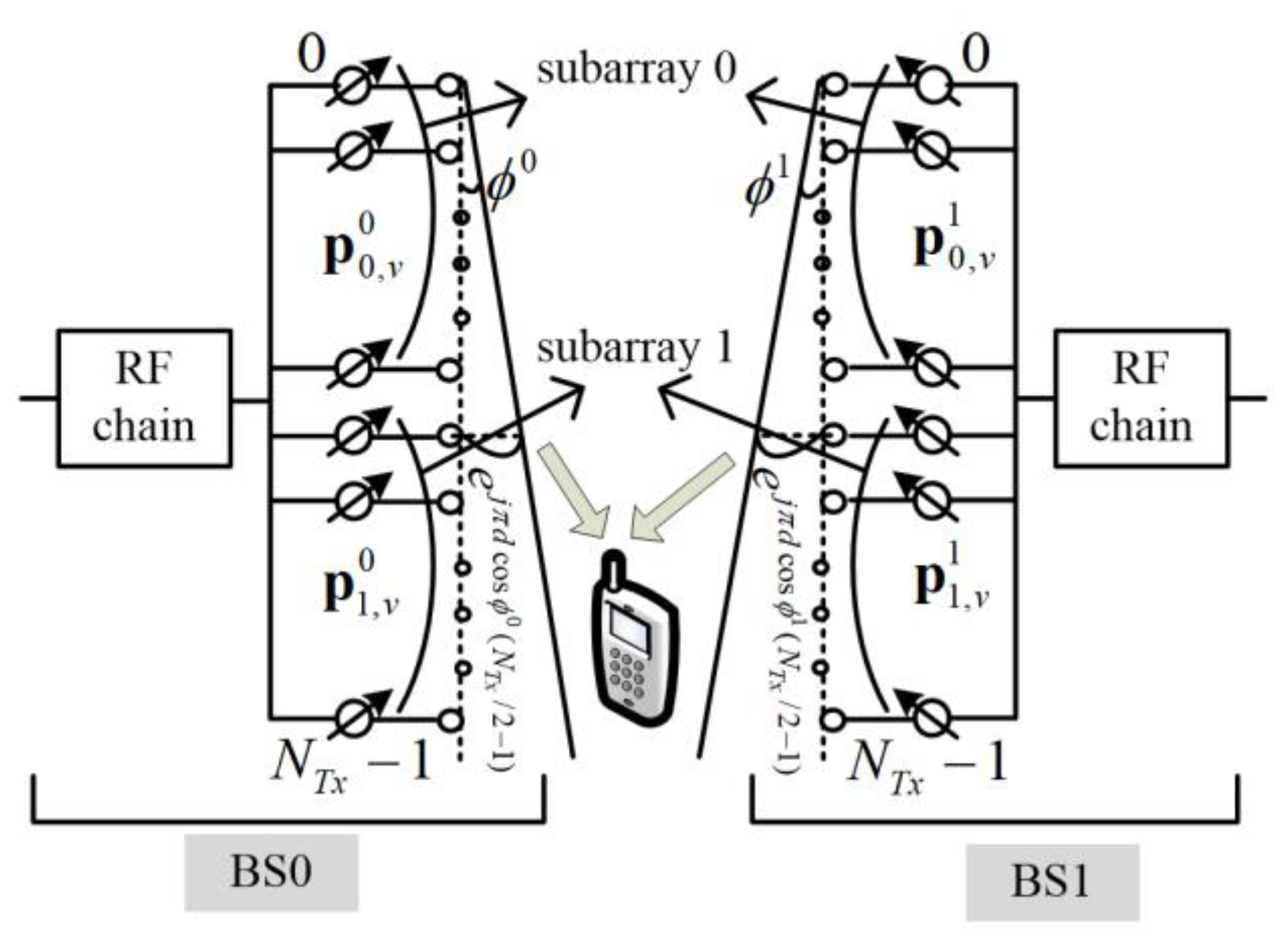
2.1. Proposed Beam Weight Generation Mehtod

Unlike the other beamforming systems, the beam weight in the proposed method is generated using a ZC sequence with CID information of the BS. The ZC sequence is especially suitable for beam weight generation in mmWave cellular systems with a beamformer because it allows an MS to distinguish neighboring BSs and multiple beams generated by the BSs. Although the ZC sequence has not been used for beam weight generation previously, it is often used for the design of synchronization signal and pilot signal owing to its good correlation property and low peak-to-average power ratio (PAPR) [18,19]. In the proposed method, the CID of the BS is mapped to the root index of the ZC sequence. It is assumed that a BS has a uniform linear array (ULA) with N T x antenna elements, which is divided into B subarrays ( N S A = N T x / B antenna elements in a subarray). The beam weights of the n T x -th antenna element in the v -th symbol of the beam training period are generated by the ZC sequence with a root index γ as follows [19,20]:
[ p v c ] n T x = [ p b , v c ] n S A = d b , v γ [ z m v γ + G b γ γ ] n S A = d b , v γ z m v γ + G b γ + n S A γ = d b , v γ e j π γ ( m v γ + G b γ + n S A ) ( m v γ + G b γ + n S A + 1 ) / N S A = d b , v γ e j π γ n S A ( n S A + 1 ) / N S A e j 2 π γ ( m v γ + G b γ ) / N S A e j π γ ( m v γ + G b γ ) ( m v γ + G b γ + 1 ) / N S A
where z n γ = e j π γ n ( n + 1 ) / N S A . Here, z n γ , p v c and p b , v c are the n - th element of the ZC sequence with a root index γ , beam weight vector with N T x , b - th subarray beam weight vector with N S A elements, respectively. Also, m v γ and G b γ are the amount of cyclic shift of the v - th symbol and b - th subarray, respectively. The parameters, c = γ 1 , b = n T x / B , n S A = ( n T x ) % N S A , and z n γ are the CID, subarray index, antenna element index in a subarray, and n - t h element of a ZC sequence with a root index γ and length N S A , respectively. z m v γ + G b γ γ denotes a vector composed of the ZC sequence with the root index γ and cyclic shift m v γ + G b γ . Also, % and [ . ] n denote the modulo operation and n - t h element in a vector. In addition, d b , v γ and v denote a complex constant determined by parameters ( γ , b , v ) and the index of Tx beamforming weight vector of BS, respectively. The values of c , b , and v are ranged from 0 to ( N S A 2 ) , from 0 to ( B 1 ) , and from 0 to ( N S A 1 ) , respectively. The Tx beams are generated by increasing the index v in Equation (1) from 0 to ( N S A 1 ) . This procedure is repeated until one round of an Rx beam sweep is completed. If ( γ m v γ ) % N S A , ( γ G b γ ) % N S A , and d b , v γ are given by v , b , and ( [ z 0 γ ] m v γ + G b γ ) * respectively, [ p b , v c ] n S A can be expressed as
[ p b , v c ] n S A = z n S A γ e j 2 π b n S A / N S A e j 2 π v n S A / N S A
Note that the beampatterns generated by the subarray beam weight vector in Equation (1) are determined by the parameters ( γ , b , v , N S A ).
The signal received at the i - th Rx beam of the MS from BS with CID c in the v -th period can be represented by [5]
r v , i c = ( m i ) H b = 0 B 1 p = 0 N P 1 H p p b , v c x v c + ( m i ) H w v = b = 0 B 1 p = 0 N P 1 h p { ( m i ) H a p c , R x } { ( a p c , T x ) H p b , v c } x v c + ( m i ) H w v = b = 0 B 1 p = 0 N P 1 h p { ( m i ) H a p c , R x } n = 0 N T x 1 e j 2 π n d cos ϕ p c [ p b , v c ] n x v c + w v , i = b = 0 B 1 p = 0 N P 1 h p η p , i c n T x = 0 N T x 1 z n T x γ = c + 1 e j 2 π ( b + v N T x d cos ϕ p c ) n T x / N T x x v c + w v , i = b = 0 B 1 p = 0 N P 1 h p η p , i c y b , v c + w v , i
where H p = p = 0 N P 1 h p a p c , R x ( a p c , T x ) H , w v , i = ( m i ) H w v , η p , i c = ( m i ) H a p c , R x , [ a p c , R x ] n = e j 2 π n d cos θ p c , [ a p c , T x ] n = e j 2 π n d cos ϕ p c , and y b , v c = n T x = 0 N T x 1 z n T x γ = c + 1 e j 2 π ( b + v N T x d cos ϕ p c ) n T x / N T x . Here, m i is the DFT-based beam weight vector for the i -th Rx beam. Also. a p c , R x and a p c , T x are AoA and AoD vectors for the p -th path in a cell with CID c . H p and η p , i c are channel matrix and Rx beam gain for the p -th path, respectively. d denotes the antenna spacing normalized by the wavelength of the carrier and is set to 0.5. θ p c , ϕ p c , and h p denote the AoA, AoD and channel coefficient of the p -th path in a cell with CID c , respectively. w v and w i , v denote an additive white Gaussian noise vector in the v - th training symbol and the noise signal received at the i -th Rx beam, respectively. Also, x v c denotes the preamble transmitted from the BS with CID c . Here, x v c is set to 1 to focus on the effect of beam weight in the proposed method. The dispersions in time and frequency domains are not considered in Equation (3) because the channel is assumed to have a strong LOS path. Then, when ϕ p c is 0, y b , v c becomes discrete Fourier transform (DFT) of ZC sequence with a phase rotation corresponding to the subarray index b . This means that the BSs with different CID and subarray index generate different signals y b , v c with v ranging from 0 to ( N S A 1 ) . Therefore, y b , v c with v ranging from 0 to ( N S A 1 ) can be considered as the training signal transmitted from each BS with CID c and subarray b .
Figure 1 shows an example of Tx beamformers at two neighboring BSs when the proposed beam weight generation method in Equation (1) is used. In this example, the Tx beamformers at the BSs have two subarrays, each consisting of N T x / 2 elements. The weights of Tx beamformers are determined by the values of BS’s CID and subarray index b . Note that the beam patterns of BSs in the proposed method are different because their beam weights are generated with different root indices. This enables MSs to distinguish BSs, with the received signals. In the figure, the Rx beam at the MS is ignored for simplicity.

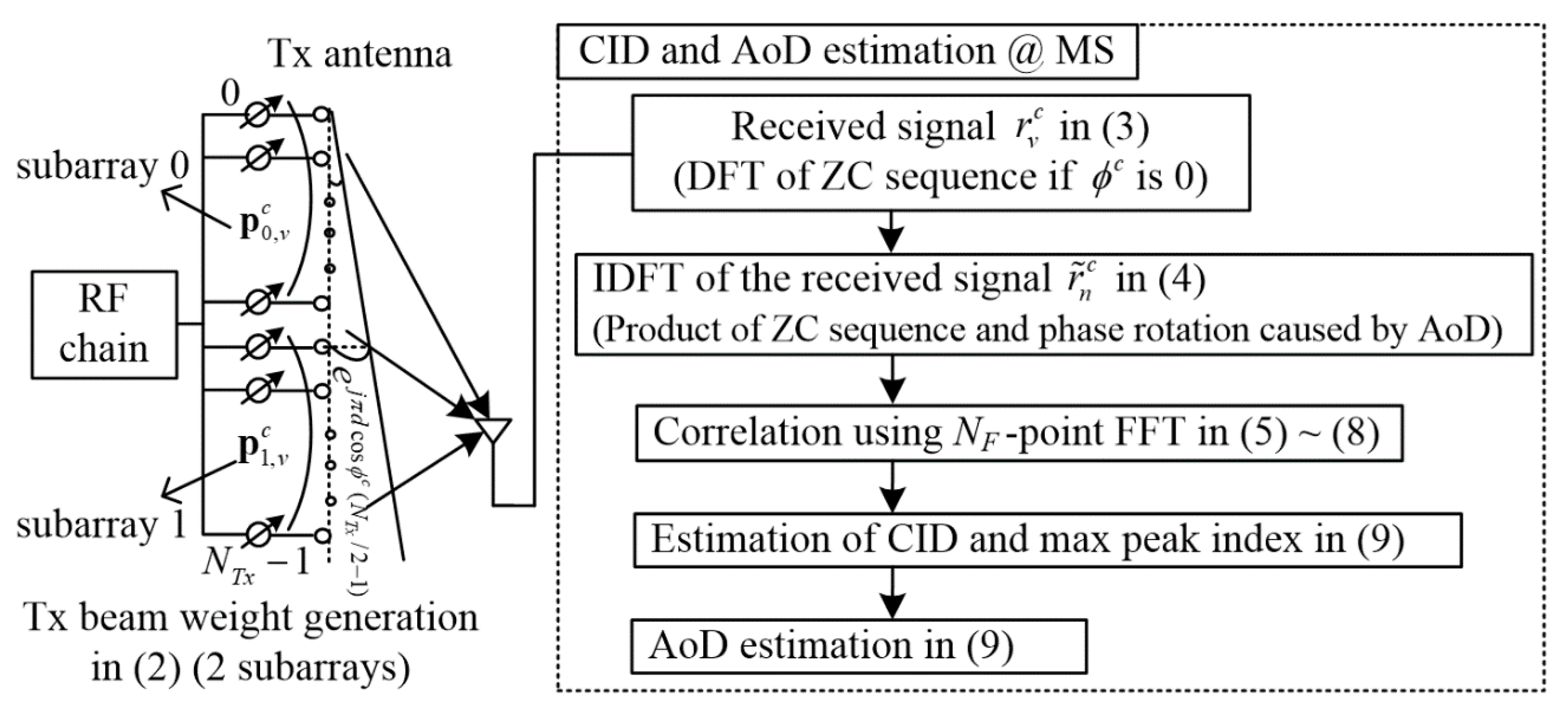
2.2. CID and AoD Estimation Method

This section describes the method of estimating CID and AoD, using the signals received at an MS in a mmWave cellular system. As discussed in Section 2, the received signal in Equation (3) becomes the summation of the DFT of the ZC sequences with the root index corresponding to CID and the cyclic shift corresponding to subarray index b when ϕ p c is 0. When ϕ p c is not 0, the received signal is additionally cyclic-shifted by the amount d cos ϕ p c . Therefore, if the inverse discrete Fourier transform (IDFT) operation is applied to the received signal, the result becomes the summation of ZC sequences multiplied by a linear phase rotation with a slope corresponding to the subarray index b and d cos ϕ p c caused by AoD. After the IDFT operation, the IDFT of the signal received from the BS with CID c at the i - th Rx beam in the MS is given as follows:
r ˜ i , n c = v = 0 N S A 1 r v , i c e j 2 π v n / N T x = b = 0 B 1 h 0 η 0 , i c e j 2 π n d cos ϕ p c e j 2 π b n / N T x z n γ + ω i , n c + w ˜ i , n , n = 0 , , N S A 1
where ω i , n c = b = 0 B 1 p = 1 N P 1 h p η p , i c e j 2 π n d cos ϕ p c e j 2 π b n / N T x z n γ . Here, h 0 and ω are the channel coefficient of the dominant path, and the remaining terms except the dominant path in the received signal. If the ZC sequence is descrambled after the IDFT operation, only the phase rotation term remains in the received signal. Then, the correlation between the IDFT of the received signal in Equation (4) and the ZC sequence used for beam weight generation in Equation (1) is performed using the N F -point FFT as follows:
A i , k c , γ ˜ = n = 0 N F 1 r i , n c ( z n γ ˜ ) * e j 2 π n k / N F
where r i , 0 n < N T x c = r ˜ i , n c , r i , N T x n < N F c = 0 , z 0 n < N T x γ ˜ = z n γ ˜ , and z N T x n < N F γ ˜ = 0 . Here, k denotes the sample index of FFT output.
When γ ˜ is γ , Equation (5) is given by
A i , k c , γ = b = 0 B 1 h 0 η 0 , i c n = 0 N T x 1 e j 2 π n ( d cos ϕ 0 c + b / N T x k / N F ) + n = 0 N F 1 ( ω i , n c + w ˜ n ) ( z n γ ˜ ) * e j 2 π n k / N F = b = 0 B 1 h 0 η 0 , i c A b , k c , γ + n = 0 N F 1 ( ω i , n c + w ˜ n ) ( z n γ ˜ ) * e j 2 π n k / N F
where A b , k c , γ = e j π ( N T x 1 ) Θ b , k r sin ( π N T x Θ b , k γ ) / sin ( π Θ b , k γ ) , Θ b , k γ = Θ k γ + b / N T x , and Θ k γ = d cos ϕ c k / N T x . From A b , k c , γ , the AoD of the dominant path can be estimated. First, the value of k maximizing the power of A b , k c , γ in Equation (6) is calculated by
k b max = ( ( N F d cos ϕ c + b N F / N T x ) % N F )
where denotes the round operation. Note that k b + 1 max has an offset of N F / N T x against k b max in Equation (7) and A b + 1 , k b + 1 c , γ has a phase offset of e j 2 π d cos ϕ c b N S A against A b , k b c , γ in Equation (6). Using this relationship, the correlation values for the estimation of CID and AoD are obtained by combining A b , k c , γ as follows:
A ˜ i , k c , γ ˜ = 1 B b = 0 B 1 A i , k b c , γ ˜ e j 2 π d cos ϕ ˜ k b N S A
where ϕ ˜ k = { cos 1 ( 2 k / ( N F ) ) , 0 k < N F / 2 cos 1 ( 2 ( N F k ) / ( N F ) ) , N F / 2 k < N F , k = 0 ~ N F - 1 , and k b = ( k + b N F N 0 / N T x ) % N F .
In Equation (8), the peak value is located at k corresponding to the AoD of the path with the maximum received signal for each Rx beam. Using the combined correlation value, the AoD are estimated as follows:
ϕ ^ γ ^ = { cos 1 ( 2 k ^ γ ^ / ( N F ) ) , 0 k ^ γ ^ < N F / 2 cos 1 ( 2 ( N F k ^ γ ^ ) / ( N F ) ) , N F / 2 k ^ γ ^ < N F
where { i max , γ ^ , k ^ γ ^ } = argmax { i , γ ˜ , k } | A ˜ i , k c , γ ˜ | 2 . Here, i max means the Rx beam index with the maximum received power. The CID corresponding to the estimated AoD is c ^ = γ ^ 1 . Figure 2 summarizes the procedure of CID and AoD estimation using the signals received from neighboring BSs with beam weights generated by the proposed method.
Although the beamformer generated by the proposed beam weight generation method has a random beam pattern, the Signal-to-Noise Ratio (SNR) gain can be obtained by the correlation operation in Equation (5). The SNR after the correlation operation in Equation (5) can be obtained using the signal and noise terms in r b c . Here, r b c denotes a received signal vector [ r 0 , i c r N S A 1 , i c ] T . When the channel has only LoS path and both B and η 0 , i c is 1, the signal component of r b c = γ 1 is given by
y 0 γ 1 = [ y 0 , 0 γ 1 y 0 , 1 γ 1 y 0 , N T x 1 γ 1 ] T = F ϕ γ 1 M z 0 γ x v c = F ϕ γ 1 z ˜ 0 γ x v c
where [ M ] k n = e j 2 π k n / N T x , [ z ˜ 0 γ ] k = z k γ 1 e j 2 π ( γ 1 1 ) ( 1 + N T x ) 2 k / N T x N T x ( α + γ N T x ) 1 + j N T x 1 + j e j π γ α α + N T x [20], α ± = ( N T x ± 1 ) / 2 , ( γ 1 γ ) % N T x = 1 . Here, γ 1 denotes a modulo inverse of γ . When N is a prime number, ( a / N T x ) becomes a Legendre symbol. The term ( a / N T x ) becomes ± 1 when α is not 0. Also, [ F ϕ γ 1 ] k δ is the element in the k -th row and δ -th column of F ϕ γ 1 , which is a circular matrix and a function of AoD. F ϕ γ 1 is expressed as follows:
[ F ϕ γ 1 ] k δ = e j π ( Θ k γ ) ( N T x 1 ) sin ( π n N T x Θ k γ ) / sin ( π n Θ k γ ) / N T x
where ( F ϕ γ 1 ) H F ϕ γ 1 = I . When the Tx signal x v c is a constant 1 / N T x , the correlation value of ( F ϕ γ 1 z ˜ 0 γ ) H y 0 γ 1 becomes ( N T x ) 2 and its power becomes ( N T x ) 3 . Also, when w is a noise vector [ w 0 , i w N S A 1 , i ] T , the average power of ( F ϕ γ 1 z ˜ 0 γ ) H w becomes σ 2 ( N T x ) 2 . When w v , i has an average power of σ 2 , the SNR after the correlation operation in Equation (5) becomes N T x / σ 2 (total Tx power is 1). Thus, the SNR gain that can be achieved by the proposed beam weight generation method is given by N T x due to the processing gain obtained by the correlation operation for CID and AoD estimation. This SNR gain is the same as the beamforming gain of ULA with the conventional DFT-based beamforming weight. In addition to the SNR gain, the periodic correlation between y 0 r 1 and z ˜ 0 γ ˜ with a root index γ ˜ is given by
μ γ ˜ , γ = ( Z ˜ 0 γ ˜ ) H r γ 1 / N T x = ( Z ˜ 0 γ ˜ ) H F ϕ γ 1 z ˜ 0 γ / N T x
where [ Z ˜ 0 γ ] k δ = [ z ˜ δ γ ] k = [ z ˜ 0 γ ] ( k δ ) % N 0 . When ϕ γ 1 is 0 (broadside), the absolute value of [ μ γ ˜ , γ ] k in Equation (12) becomes N T x using the correlation property of the ZC sequence [19].

3. Simulation Results and Discussion

In this section, the performance of CID and AoD estimation in an mmWave cellular system is evaluated by simulation when the proposed beam weight generation method is used. Simulation is performed with a simple mmWave cellular model in a LOS dominant condition. It is assumed that an MS is located at the cell boundary of three cells. The distance between the MS and three BSs are the same. AoAs at the MS are set to −30°, 0°, and 30° for three neighboring cells. AoDs at three BSs are randomly selected from a value ranging from −90° to 90°. Also, ULA antennas with N T x and N R x are used at the BS and MS, respectively. N R x is set to 16 and the number of available CIDs (maximum number of CIDs) M is set to N S A 1 . The channel between each BS and MS is assumed to experience Rician fading, consisting of a LoS path and a non-line-of-sight (NLOS) path. The non-line-of-sight (NLOS) path is generated by the spatial channel model (SCM), and composed of 20 rays with 2° azimuth spread. The power of NLoS path is 15 dB less than the power of LoS path [21].
In the simulation, the proposed method is compared with the conventional method in terms of performance and overhead. In the conventional methods, the DFT-based beamforming weight is used for Tx beamformer at the BS and the OMP algorithm is used for AoD estimation at the MS [8,9]. In the proposed method, the signals generated by the beam weights with CID information (BSs) are simultaneously transmitted since the proposed method allows an MS to distinguish neighboring BSs. In the conventional beam training method, the BS transmits single Tx beams generated by the DFT-based orthonormal RF precoder until all the Tx beams are transmitted. Here, BSs are distinguished by the time slots assigned differently depending on their CIDs. The MS sweeps the Rx beam. The beam sweeping operation is performed for all neighboring BSs to select a serving BS. The MS estimates the signal quality and AoD of the serving BS by applying the OMP algorithm.
Figure 3 and Figure 4 show the performance of CID detection and AoD estimation when the conventional and proposed methods are used, respectively. The following combinations of ( N S A , B ) are used for the proposed method in the simulation: (17,1), (17,2), (31,1), and (31,2). The large (☆,▷) and small (○,◇,□,△) markers in the figure represent the conventional and proposed methods, respectively. In the proposed method, N F is set to 256, implying that the angle resolution in the AoD estimation is approximately given by 180° divided by 256. For the conventional method, N T x is set to 17 ( B =1), and the angle resolution of the OMP technique is set to be the same as that of the proposed method. The Tx power at the BS is set to 1 regardless of the value of B . From Figure 3, it can be seen that the performances of CID detection decrease as N S A decreases, as indicated by the numbers 31 (□,△,▷) and 17 (○,◇,☆), because the SNR gain decreases as the number of antenna elements decreases. For example, the CID detection performance of the proposed method, (17,1) (○), is degraded by about 2.5 dB, compared with that of (31,1) (□), in a low SNR region. From this figure, it can be also seen that the CID detection probability of B = 2 is degraded by about 0.5 dB compared to that of B = 1 due to the effect of subarrays in the combining process. In Figure 4, the mean absolute error of AoD is measured only when the CID detection is performed successfully. From this figure, it can be seen that the AoD estimation performance is degraded as N T x decreases, because the correlation peak becomes smoother as N T x decreases. From Figure 3 and Figure 4, one can conclude that the conventional and proposed methods have similar performance in CID detection and AoD estimation.
Table 2 shows the processing time required for beam training in the conventional and proposed methods when a different set of parameters is used. Here, the processing time is normalized by the sampling interval. This table shows that the processing time in the conventional method increases linearly in proportion to N T x , N R x , and M . However, the number of neighboring BSs has little effect on the processing time when the proposed method is used. In the table, M is N S A 1 . The processing time of the proposed method is mainly affected by N S A and N R x . In the table, the ratio of the processing time of the proposed method to that of the conventional method is N S A / M / N T x (1.6–6.25%).

4. Conclusions

This paper proposes a new method of CID and AoD estimation for mmWave cellular systems with beamformers, where different beam weights generated by ZC sequence are used for neighboring BSs in the initialization stage. The performance of the proposed method is compared with the conventional method by simulation with a simple mmWave cellular model in a LOS dominant condition. Simulation results show that the performances of CID detection and AoD estimation of the proposed method are similar to those of the conventional method even though the beam training signals in the proposed method are transmitted simultaneously from all neighboring BSs. That is because the signals generated by the proposed beam weights have a low correlation among different BSs and zero correlation among different beams transmitted from the same BS. The proposed method can reduce the processing time (1.6–6.25%), compared with the conventional method. In this paper, CID and AoD estimation method is presented for mmWave cellular systems in LOS dominant conditions. In the future, we plan to analyze the performance of the proposed method in mmWave channels with no dominant LOS path.

Author Contributions

Y.J.K. developed the CID and AoD estimation technique for mmWave cellular systems. Y.S.C. supervised the project. All authors have read and agreed to the published version of the manuscript.

Funding

This research was supported by the National Research Foundation of Korea (NRF) grant funded by the Korea government (MSIT) (2018R1A4A1023826) and (2018R1A2B2002621).

Conflicts of Interest

The authors declare no conflicts of interest.

References

  1. Garcia, N.; Wymeersch, H.; Slock, T.M. Optimal precoders for tracking the AoD and AoA of a mmWave path. IEEE Trans. Signal Process. 2018, 66, 5718–5729. [Google Scholar] [CrossRef] [Green Version]
  2. Marandi, M.K.; Rave, W.; Fettweis, G. Beam selection based on sequential competition. IEEE Signal Process. Lett. 2019, 26, 455–459. [Google Scholar] [CrossRef]
  3. Zhao, X.; Abdo, A.M.A.; Zhang, Y.; Geng, S.; Zhang, J. Single RF-chain beam training for MU-MIMO energy efficiency and information-centric IoT millimeter wave communications. IEEE Access 2018, 7, 6597–6610. [Google Scholar] [CrossRef]
  4. Hur, S.; Kim, T.; Love, D.J.; Krogmeier, J.V.; Thomas, T.A.; Ghosh, A. Millimeter wave beamforming for wireless backhaul and access in small cell networks. IEEE Trans. Commun. 2013, 61, 4391–4403. [Google Scholar] [CrossRef] [Green Version]
  5. Alkhateeb, A.; Ayach, O.E.; Leus, G.; Heath, R.W. Channel estimation and hybrid precoding for millimeter wave cellular systems. IEEE J. Sel. Top. Sign. Process. 2014, 8, 831–846. [Google Scholar] [CrossRef] [Green Version]
  6. Zhu, D.; Choi, J.; Heath, R.W. Auxiliary beam pair enabled AoD and AoA estimation in closed-loop large-scale millimeter-wave MIMO systems. IEEE Trans. Wirel. Commun. 2017, 16, 4770–4785. [Google Scholar] [CrossRef]
  7. Zhu, D.; Choi, J.; Heath, R.W. Two-dimensional AoD and AoA acquisition for wideband millimear-wave with dual-polarized MIMO. IEEE Trans. Wirel. Commun. 2017, 16, 7890–7904. [Google Scholar] [CrossRef]
  8. Lee, J.; Gil, G.T.; Lee, Y.H. Channel estimation via orthogonal matching pursuit for hybrid MIMO systems in millimeter wave communications. IEEE Trans. Commun. 2016, 64, 2370–2386. [Google Scholar] [CrossRef]
  9. Marzi, Z.; Ramasamy, D.; Madhow, U. Compressive channel estimation and tracking for large arrays in mm-wave picocells. IEEE J. Sel. Top. Signal. Process. 2016, 10, 514–527. [Google Scholar] [CrossRef] [Green Version]
  10. Fang, J.; Wang, F.; Shen, Y.; Li, H.; Blum, R.S. Super-resolution compressed sensing for line spectral estimation: An iterative reweighted approach. IEEE Trans. Signal. Process. 2016, 64, 4649–4662. [Google Scholar] [CrossRef]
  11. Hu, C.; Dai, L.; Mir, T.; Gau, Z.; Fand, J. Super-resolution channel estimation for mmWave massive MIMO with hybrid precoding. IEEE Trans. Veh. Technol. 2018, 67, 8954–8958. [Google Scholar] [CrossRef] [Green Version]
  12. IEEE Computer Society. Part 11: Wireless LAN Medium Access Control (MAC) and Physical Layer (PHY) Specification. IEEE 802.11ad Standard; IEEE: New York, NY, USA, 2012. [Google Scholar]
  13. Li, Y.; Luo, J.; Garcia, M.H.C.; Böhnke, R.; Stirling-Gallacher, R.A.; Xu, W.; Caire, G. On the beamformed broadcasting for millimeter wave cell discovery: Performance analysis and design insight. IEEE Trans Wirel. Commun. 2018, 17, 7620–7634. [Google Scholar] [CrossRef]
  14. Liu, C.; Li, M.; Hanly, S.V.; Whiting, P.; Collings, I.B. Millimeter-wave small cells: Base station discovery, beam alignment, and system design challenges. IEEE Wirel. Commun. 2018, 25, 40–46. [Google Scholar] [CrossRef]
  15. Trees, H.L.V. Optimum Array Processing; John Wiley & Sons: New York, NY, USA, 2002. [Google Scholar]
  16. Liberti, J.C.; Rappaport, T.S. Smart Antennas for Wireless Communications; Prentice Hall: Upper Saddle River, NJ, USA, 1999. [Google Scholar]
  17. Godara, L.C. Smart Antennas; CRC Press: Boca Raton, FL, USA, 2000. [Google Scholar]
  18. Chu, D.C. Polyphase codes with good periodic correlation properties. IEEE Trans. Inf. Theory 1972, 18, 531–532. [Google Scholar] [CrossRef]
  19. Zepernick, H.J.; Finger, A. Pseudo Random Signal Processing Theory and Application; John Wiley & Sons: Hoboken, NJ, USA, 2005. [Google Scholar]
  20. Beyme, S.; Leung, C. Efficient computation of DFT of Zadoff-Chu sequences. Electron. Lett. 2009, 45, 461–463. [Google Scholar] [CrossRef]
  21. Hemadeh, I.A.; Satyanarayana, K.; El-Hajjar, M.; Hanzo, L. Millimeter-wave communications: Physical channel models, design considerations, antenna constructions, and link-budget. IEEE Comm. Surv. Tutor. 2018, 20, 870–913. [Google Scholar] [CrossRef] [Green Version]
Figure 1. An example of Tx beamformers at two neighboring BSs when the proposed beam weight generation method is used.
Electronics 09 00335 g001
Figure 2. The procedure of the proposed CID and AoD estimation.
Electronics 09 00335 g002
Figure 3. The performance of CID detection when the conventional and proposed methods are used (3 BSs, Rician, K = 15 dB, 1 RF).
Electronics 09 00335 g003
Figure 4. The performance of AoD estimation when the conventional and proposed methods are used (3 BSs, Rician, K = 15 dB, 1 RF).
Electronics 09 00335 g004
Table 1. Notation table.
NotationMeaningNotationMeaning
N T x Number of Tx antennas m v γ Amount of cyclic shift of v - th symbol for beam weight vector with root index γ
B Number of subarrays G b γ Amount of cyclic shift of b - th subarray for beam weight vector with root index γ
N S A Number of antenna elements in a subarray d b , v γ Complex constant determined by ( γ , b , v )
n T x Tx antenna element index m i DFT-based beam weight vector for i -th Rx beam
n S A Antenna element index in a subarray a p c , R x AoA vector for p -th path in a cell with CID c
v Symbol index in beam training period a p c , T x AoD vector for p -th path in a cell BS with CID c
γ Root index of ZC sequence H p Channel matrix for p -th path
b Subarray index η p , i c Beam gain of i - th Rx beam of MS for p -th path in a cell with CID c
c Cell ID (CID) θ p c AoA of p -th path in a cell with CID c
i Rx beam index ϕ p c AoD of p -th path in a cell with CID c
p Path index of channel h p Channel coefficient of p -th path
k Sample index of FFT output w v AWGN vector in v - th training symbol period
z n γ n - th element of ZC sequence with a root index γ w i , v Noise signal received at i -th Rx beam in v - th training symbol period
p v c Beam weight vector of BS with CID c in v - th symbol period r v , i c Time-domain signal received from BS with CID c at i - th Rx beam in MS
p b , v c Beam weight vector of b - th subarray of BS with CID c in v - th symbol period r ˜ i , n c IDFT of signal received from BS with CID c at i - th Rx beam in MS
Table 2. Processing time (normalized by the sampling interval) required for beam training in the conventional and proposed methods.
( N T x , N S A , N R x ) Conventional Method
( N S A 1 ) N T x N R x
Proposed Method
N S A N R x
17, 17, 164352272
34, 17, 168704272
31, 31, 1615,376496
62, 31, 1630,752496

