Article

An Interference Suppression Method for Non-Contact Bioelectric Acquisition

School of Electronic Science and Engineering, Nanjing University, Nanjing 210046, China
*
Author to whom correspondence should be addressed.
Electronics 2020, 9(2), 293; https://doi.org/10.3390/electronics9020293
Submission received: 14 January 2020 / Revised: 2 February 2020 / Accepted: 6 February 2020 / Published: 8 February 2020
(This article belongs to the Special Issue Design and Application of Biomedical Circuits and Systems)

Abstract

:
For non-contact bioelectrical acquisition, a new interference suppression method, named ‘noise neutralization method’, is proposed in this paper. Compared with the traditional capacitive driven-right-leg method, the proposed method is characterized with that there is an optimal gain to achieve the minimum interference output whatever for the electrode interface impedance mismatch caused by body motion and is more effective for smaller reference electrode areas. The performance of traditional capacitive driven-right-leg method is analyzed and the difficulty to suppress interference in the case of the interface impedance mismatch is pointed out. Therefore, a noise neutralization method is proposed by applying the reference electrode and a 50 Hz band-pass filter to obtain the interference of the human body and adapting the gains to neutralize the interference inputs of two acquisition electrodes and achieve the minimum interference output. The performance of the proposed method is theoretically analyzed and verified by the experiment results, which shows that the proposed method has similar performance to that of the traditional capacitive driven-right-leg method with electrode interface impedance match, while has better interference suppression ability with electrode interface impedance mismatch caused by body motion. It is suggested that the proposed method can be preferred in the case of limited reference electrode area or interface impedance mismatch.

1. Introduction

It is well-known that, with the increasing demand for personal daily health monitoring, the study of wearable bioelectrical acquisition equipment is becoming increasingly popular. The quality of acquisition signals is the primary consideration, which is closely related to the condition of electrode interface. Needle electrodes or skin abrasions are required in early bioelectrical acquisition techniques in order to acquire high quality signals [1]. Nowadays, wet electrodes (i.e., Ag/AgCl electrodes) are usually used to acquire high quality signals. However, wet electrodes may cause skin irritation and allergic contact dermatitis [2,3,4], which leads to the difficulty for long-term bioelectricity acquisition. Therefore, capacitive electrodes are often used in wearable bioelectrical acquisition equipment [5,6,7,8,9,10,11,12]. Sun et al. defined the capacitive electrode as three types, dry electrodes, insulated electrodes, and non-contact electrodes [6]. Non-contact electrodes can measure surface potential through the clothes or other dielectrics, which can overcome the limitation of traditional wet electrode. To acquire high quality bioelectric signals by non-contact electrodes, various studies are carried out, involving electrode design and the front-end design [1,2,3,5,6,11]. It is pointed out that non-contact electrodes are very susceptible to power line common mode interference (CMI) due to the high impedance of electrodes [13,14,15], and larger CMI will cause lower signal to noise ratio. Moreover, the body motion may lead to interface impedance mismatch of the electrode, and part of CMI will be changed to pseudo difference mode components (PDMC) [6,16], this will degrade the signal quality further. Therefore, it is necessary to give more attention to suppress CMI of wearable bioelectric devices to acquire high quality signal [17,18,19,20].
For CMI suppression, the driven-right-leg (DRL) method has been widely used to suppress CMI by feeding back the reverse common mode signal from the front-end output to the driving electrode on the subject (human body) [8,19,21,22,23]. Our group Ding et al. proposed an improved front-end circuit with virtual DRL circuit and verified the design by three wearable ECG applications, portable finger ECG measurement, palm ECG acquisition for cycling and chest ECG test under different motion states [24]. Xu et al. proposed a front-end design to improve common mode rejection capability by combining both the feed-forward method and the DRL method [25]. Sakuma et al. proposed a circuit structure by connecting the driving electrode to the signal ground to suppress CMI [26]. For non-contact bioelectrical acquisition, Lim et al. proposed a capacitive ECG recording system with capacitive driven-right-leg (C-DRL) circuit integrated in the chair seat [15]. The C-DRL method is a variant of DRL method and is often used to improve common mode rejection ratio (CMRR) of non-contact bioelectrical acquisition, which is characterized with all electrodes contacting the body with isolation or clothes [14,19]. For C-DRL or DRL method, large feedback gain is usually required to obtain good suppression performance, this may destroy the stability of the front-end [21]. At the same time, large area of driving electrodes is often used in C-DRL or DRL method, which presents a difficulty of wearable device implementation [14,19,21].
On the other hand, PDMC is considered as part of motion artifacts. Serteyn et al. used an injection signal to track the change of coupling capacitance, so as to estimate and reduce motion artifacts in ECG measurement [27]. A three-axis accelerometer was used to record motion information for reducing motion artifacts reduction [28]. Rodrigues et al. uses neural networks to reconstruct ECG signals with severe motion artifacts [29]. The above methods are based on additional components or complex algorithms, which are difficult to implement.
For non-contact bioelectrical acquisition of wearable devices, a new interference rejection method, named noise neutralization method, is proposed in this paper. Compared with C-DRL or DRL method, the proposed method can effectively reduce the area of the driving electrode, and has a stronger ability to suppress interference CMI and PDMC with the electrode interface impedance mismatch caused by body motion. Firstly, the performance of traditional capacitive driven-right-leg method is analyzed and the difficulty to suppress interference in the case of the interface impedance mismatch is pointed out. Secondly, the noise neutralization method is proposed to suppress interference CMI and PDMC of non-contact electrodes and the performance is compared with that of C-DRL method. Finally, the feasibility of the proposed method is further verified by wearable ECG acquisition device.

2. Methods and Models

2.1. Traditional Capacitive Driven-Right-Leg Model for Eliminating Common Mode Interference

Figure 1 is an equivalent circuit model of the dual-electrode bioelectric acquisition equipment for CMI suppression with C-DRL method, where VP is the noise source of the power supply line, VCM is the CMI of the organism relative to the earth, V’CM is the CMI of the organism relative to signal ground, CP is the coupling capacitance between the power supply line and the organism, CB is the coupling capacitance between the earth and the organism, CS is the coupling capacitance between the earth and the signal ground, ZE1 and ZE2 are the interface impedances of the two acquisition electrodes, ZE3 is the interface impedances of the driving electrode, ZA1 and ZA2 are the two equivalent input impedances of the front-ends, VO1 and VO2 are the outputs of the front-ends, and k is the gain of the inversion amplifier.
According to Kirchhoff’s current law, V’CM, VO1 and VO2 can be expressed as
V CM = Z B + Z S Z B Z P [ 1 Z P + 1 Z B + 1 A Z E 1 + 1 B Z E 2 + 1 Z E 3 ( 1 k 2 ( A + B ) ( k 1 ) Z S Z B ) ] V P ,
V O 1 = Z A 1 ( Z B + Z S ) Z B ( Z E 1 + Z A 1 ) Z P [ 1 Z P + 1 Z B + 1 A Z E 1 + 1 B Z E 2 + 1 Z E 3 ( 1 k 2 ( A + B ) ( k 1 ) Z S Z B ) ] V P ,
V O 2 = Z A 2 ( Z B + Z S ) Z B ( Z E 2 + Z A 2 ) Z P [ 1 Z P + 1 Z B + 1 A Z E 1 + 1 B Z E 2 + 1 Z E 3 ( 1 k 2 ( A + B ) ( k 1 ) Z S Z B ) ] V P ,
A = Z A 1 Z B Z E 1 Z S Z A 1 Z B + Z E 1 Z B   ,   B = Z A 2 Z B Z E 2 Z S Z A 2 Z B + Z E 2 Z B   ,   k < 0
when ZP, ZB, ZS, ZA1, ZA2, ZE1, and ZE2 are invariant, it can be concluded from (1) that V’CM can be effectively decreased by reducing the interface impedance of the driving electrode (ZE3) and increasing the gain of the inversion amplifier (|k|). However, too large a |k| may lead to the output saturation of the inverted amplifier. When the value of |k| is greater than 100, the performance will not be improved further [15]. Therefore, small ZE3 is usually used to reduce V’CM in practical applications. There are several factors affecting the impedance of the coupling capacitance of the driving electrode. Generally, increasing the coupling area of the driving electrode is the easiest way to reduce ZE3 and is widely used [2,15,16,19]. However, large area of the driving electrode is not convenient to minimize the wearable bioelectric acquisition equipment.
For the match of the electrode interface impedance, the output of differential amplifier ∆VO can be written as
Δ V O = | V O 1 V O 2 | = 0
Considering the existence of interface impedance mismatch coefficient α between two electrodes, ZE1 and ZE2 can be expressed as
Z E = Z E 1   ,   Z E 2 = ( 1 + α ) Z E 1 ,
and for the mismatch of the electrode interface impedance, PDMC ∆VO can be written as
Δ V O = Z B + Z S Z B | Z A Z A + Z E Z A Z A + ( 1 + α ) Z E | Z P [ 1 Z P + 1 Z B + 1 A Z E + 1 B ( 1 + α ) Z E + 1 Z E 3 ( 1 k 2 ( A + B ) ( k 1 ) Z S Z B ) ] V P
If the area ratio of the acquisition electrode to the driving electrode is β, the interface impedance of the driving electrode satisfies
Z E 3 = β Z E ,
The analysis can be further simplified by
Z A = Z A 1 = Z A 2 ,
Z E = Z E 1 = Z E 2 ,
For the non-contact electrode based on cotton material, the electrode interface impedance can be assumed as (11) [10].
Z E = 305   M Ω 34   pF
Considering the power line with the amplitude 220 V and the frequency 50 Hz, the following relationship is reasonable [16,22].
Z P = 100 Z B = 100 Z S = 1.6   G Ω
Generally, different front-end equivalent input impedances are required for different electrode interfaces in order to acquire high quality signals. According to American Standards [30], the relationship between the electrode interface impedance, the equivalent input impedance and the coupled capacitor impedance can be expressed by (13) and (14),
Z A = 6.7 Z E ,
  Z B = 0.05 Z E .
and PDMC ∆VO of non-contact electrodes can be derived from (9)–(14).
Δ V O = | 6.7 α 7.7 ( 7.7 + α ) | [ 50.5 + 5 7.7 + 5 7.7 + α + 5 β ( 1 k 2 ( 13.4 7.7 + α + 6.7 α 7.7 ( 7.7 + α ) ) ) ] V P
Figure 2 shows PDMC ∆VO as function of the impedance mismatch coefficient of two acquisition electrodes with different areas of the driving electrode for C-DRL method, where the value of |k| is 100 according to the setting in reference [16]. It can be seen that ∆VO increases with the increase of impedance mismatch coefficient α for constant β, decreases with the decrease of β for constant α, which means large area of the driving electrode is expected and this will limit the miniaturization of the wearable acquisition equipment.
Figure 3 shows PDMC ∆VO as functions of the gain of the inversion amplifier and the impedance mismatch coefficient of two acquisition electrodes for C-DRL method, where the blue surface represents the case of β being 1/30, the red surface represents the case of β being 1 and the yellow surface represents the case of β being 20. It can be seen that ∆VO increases with the increase of the impedance mismatch coefficient α for constant β and |k|, decreases with the increase of |k| in a certain range and is almost unchanged for |k| larger than a certain value. ∆VO can be further suppressed by the decrease of β for constant |k|, which agrees on the performance shown in Figure 3. Therefore, it is difficult for C-DRL method to suppress CMI with small area of the driving electrode, especially under the situation of the impedance mismatch of two acquisition electrodes. Therefore, a noise neutralization method is proposed to solve above difficulties.

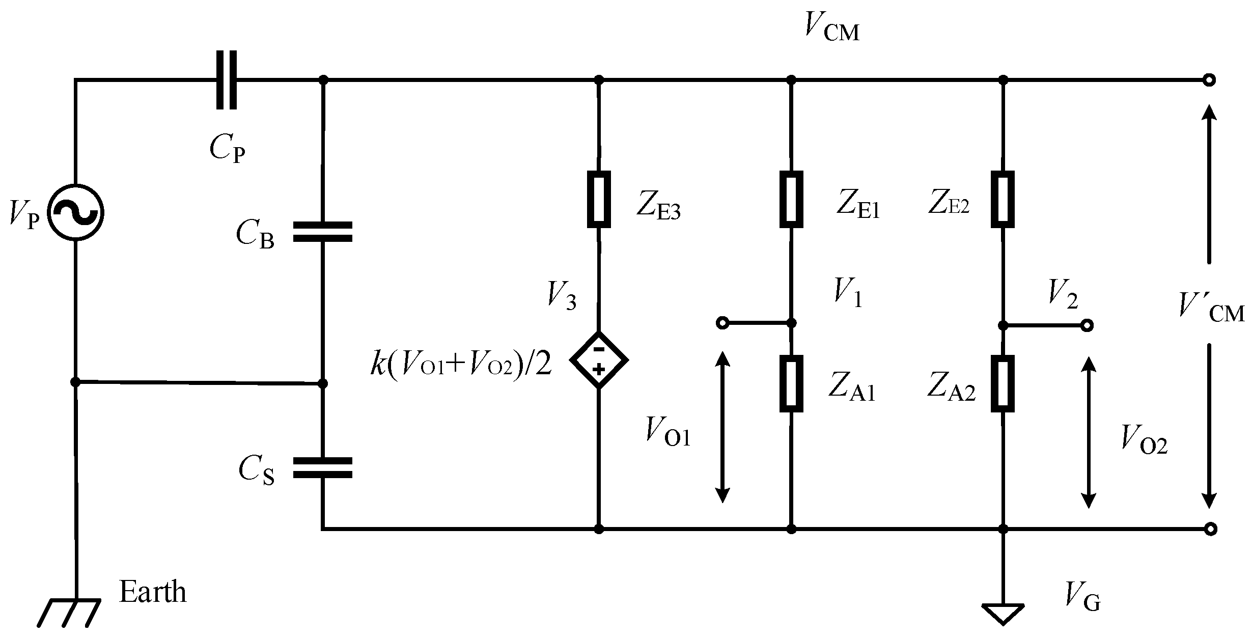
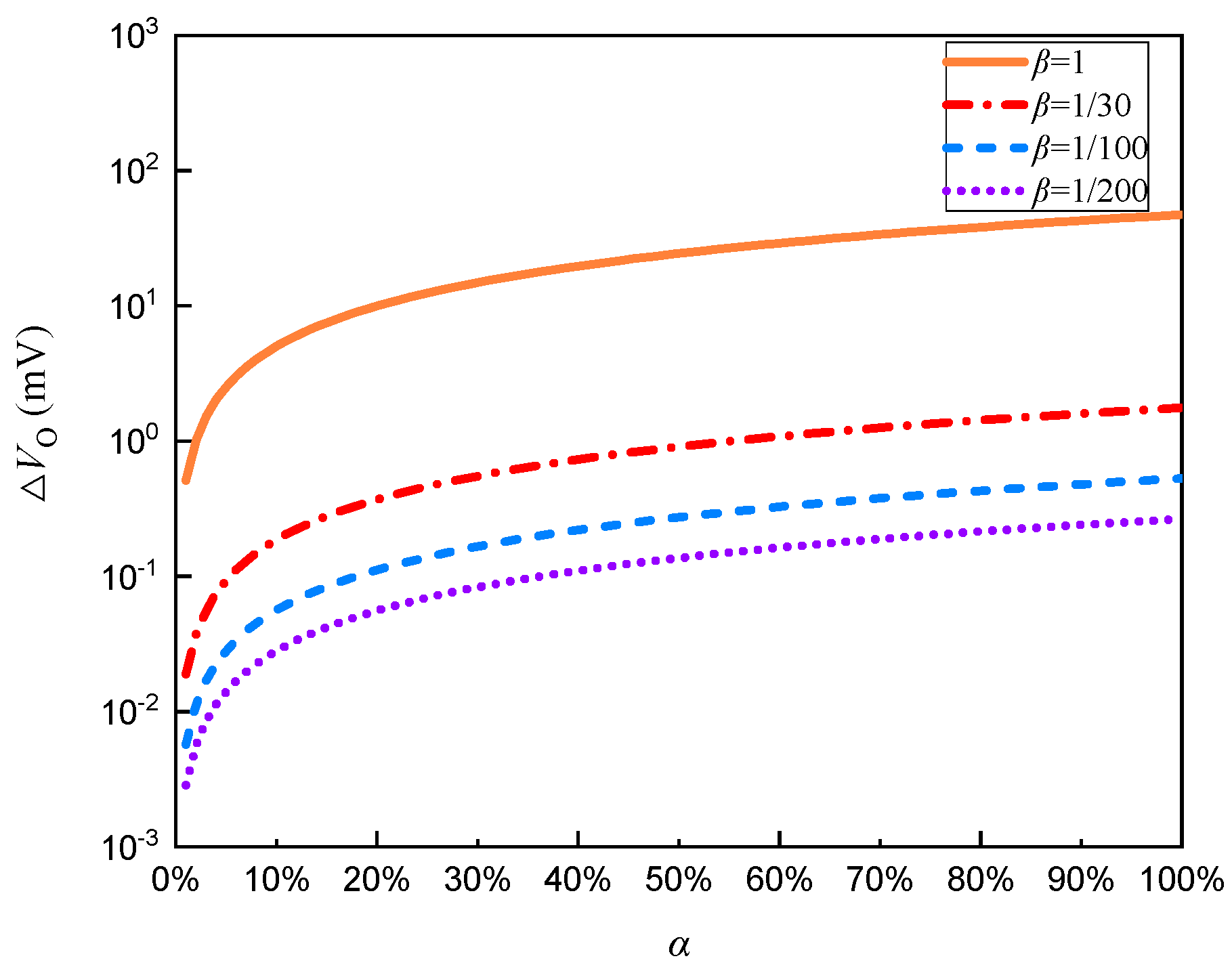
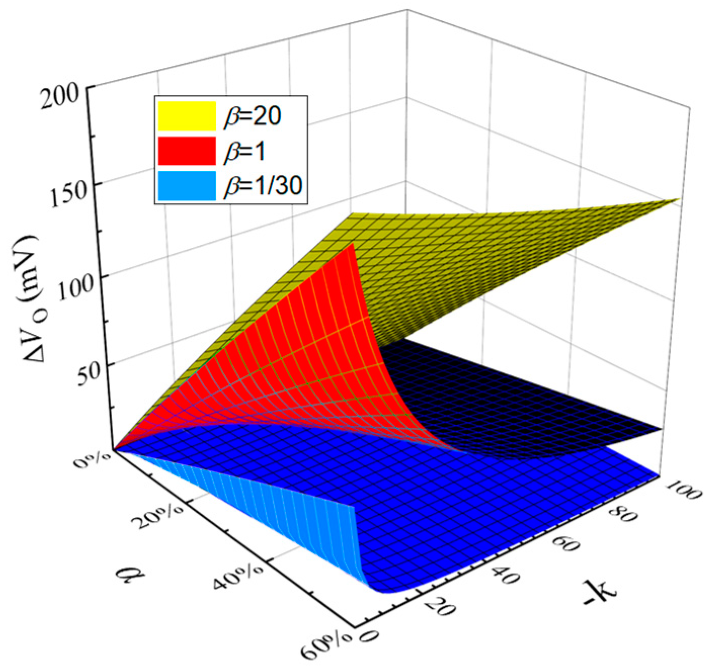
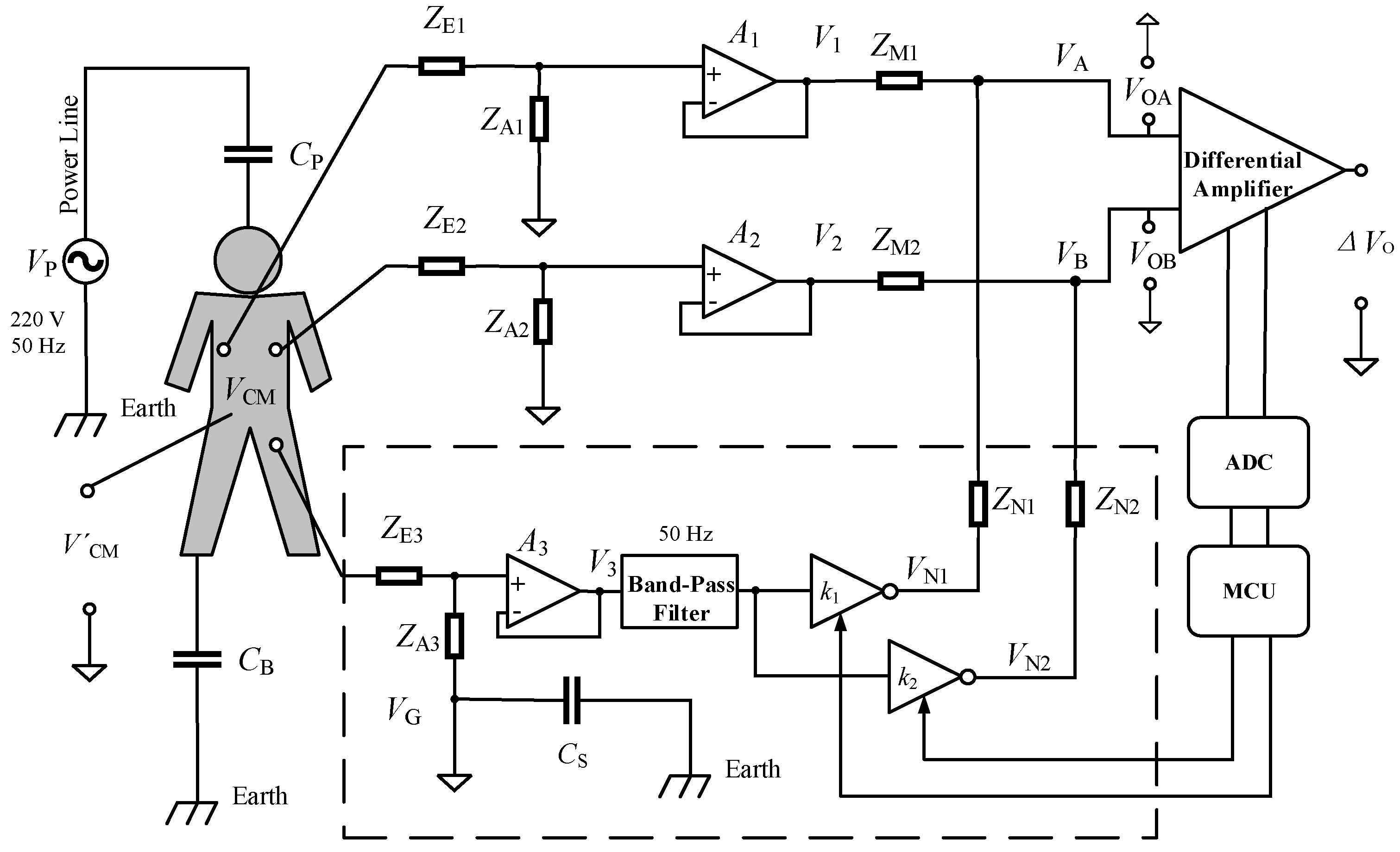
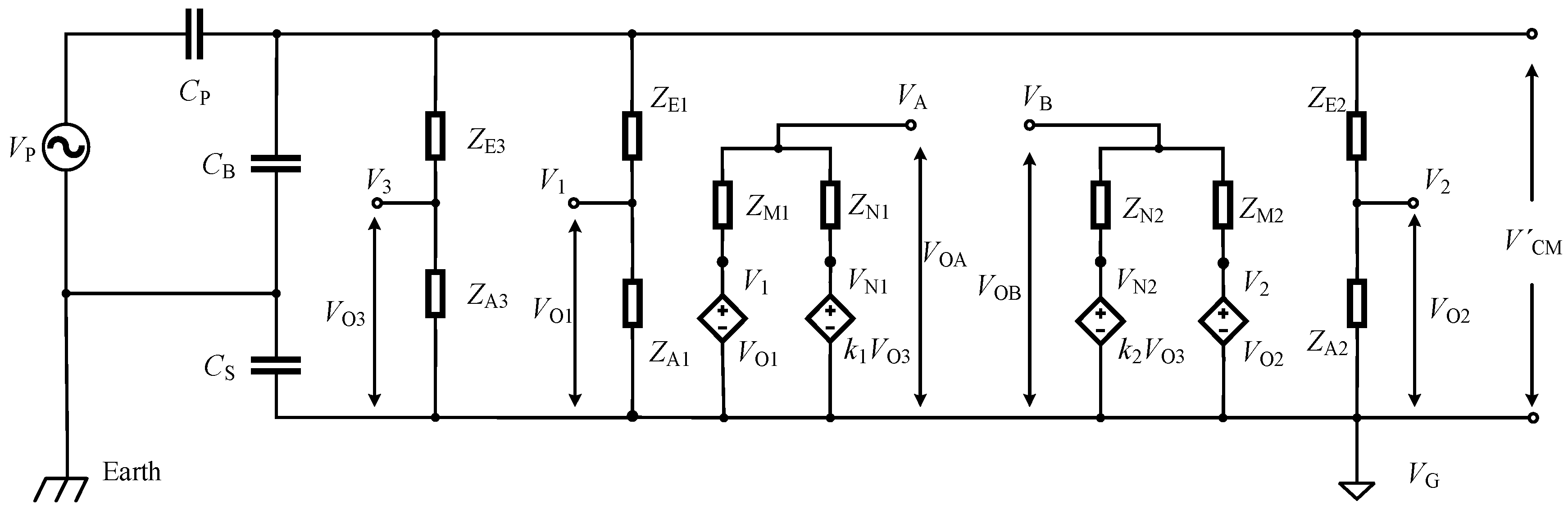
2.2. Noise Neutralization Method to Eliminate Common Mode Interference Model
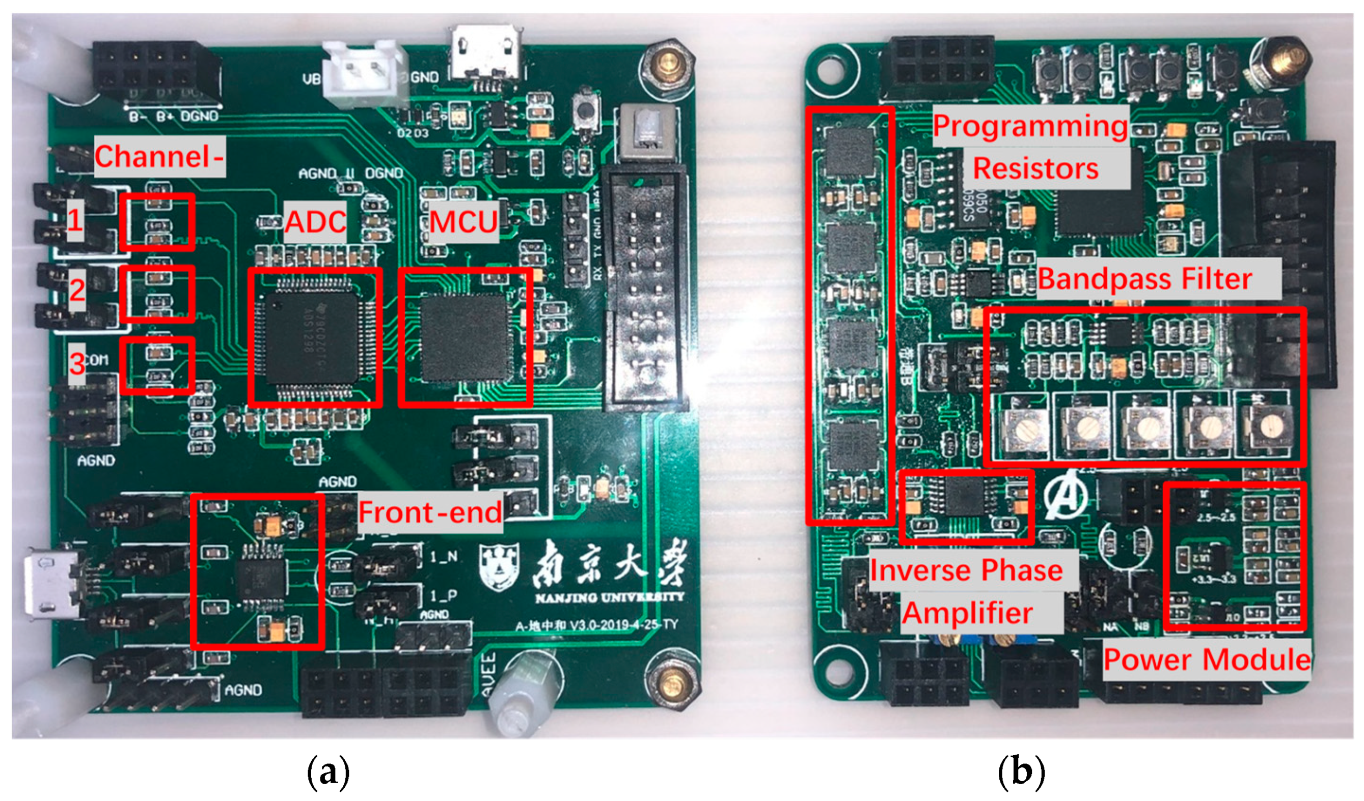
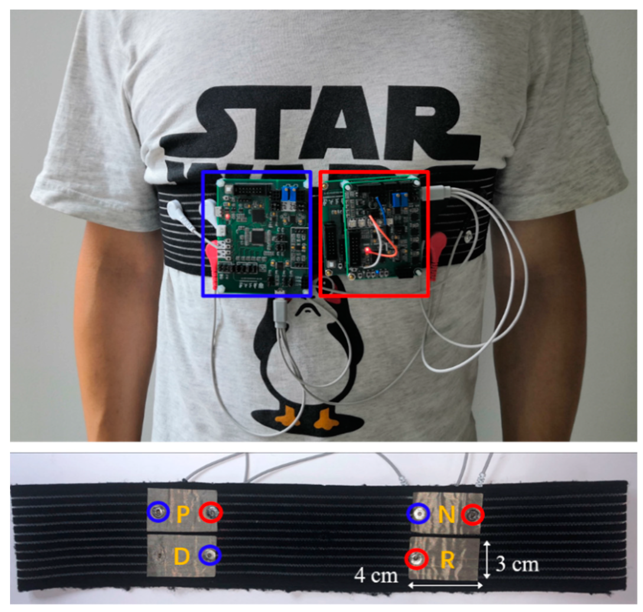
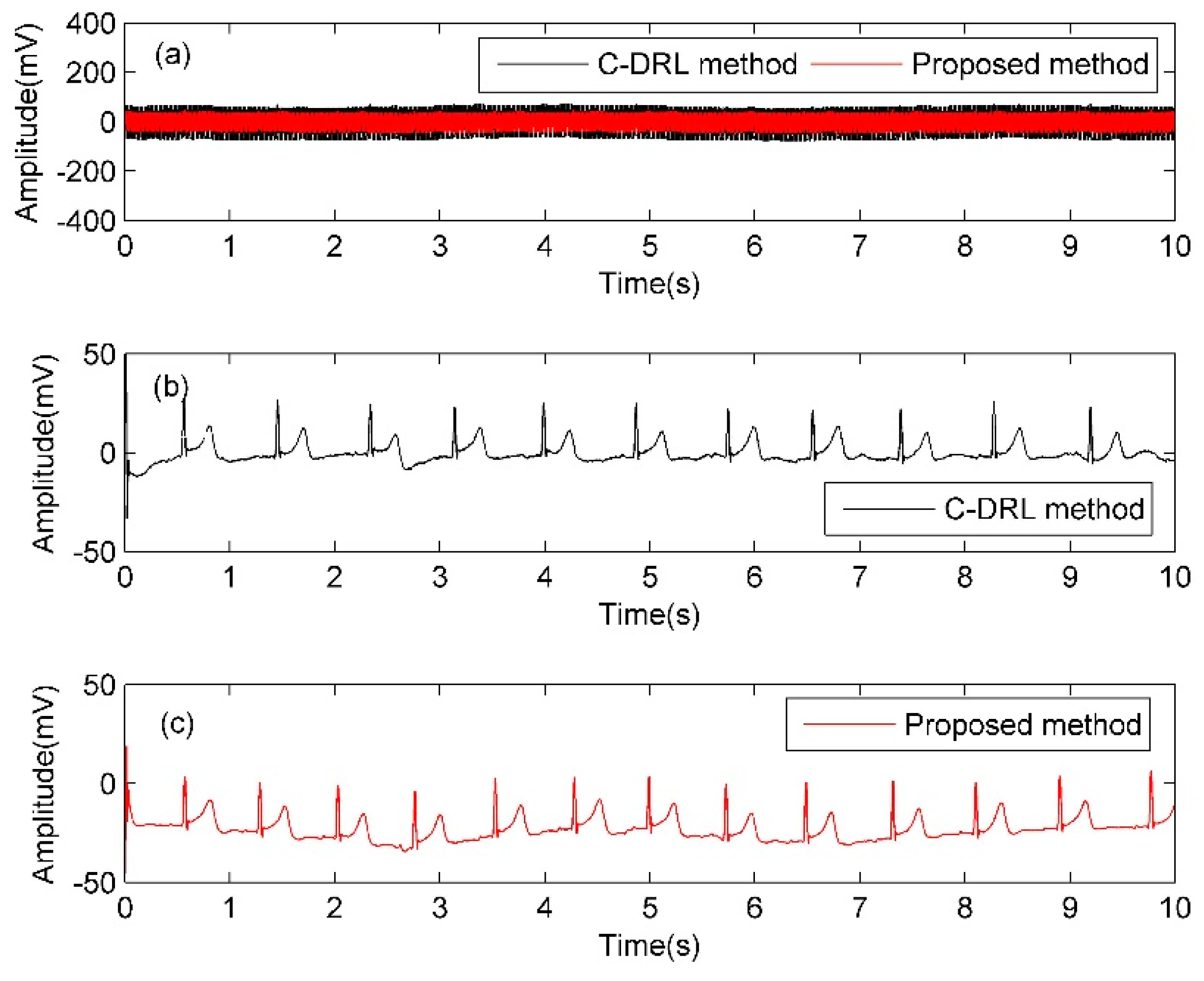
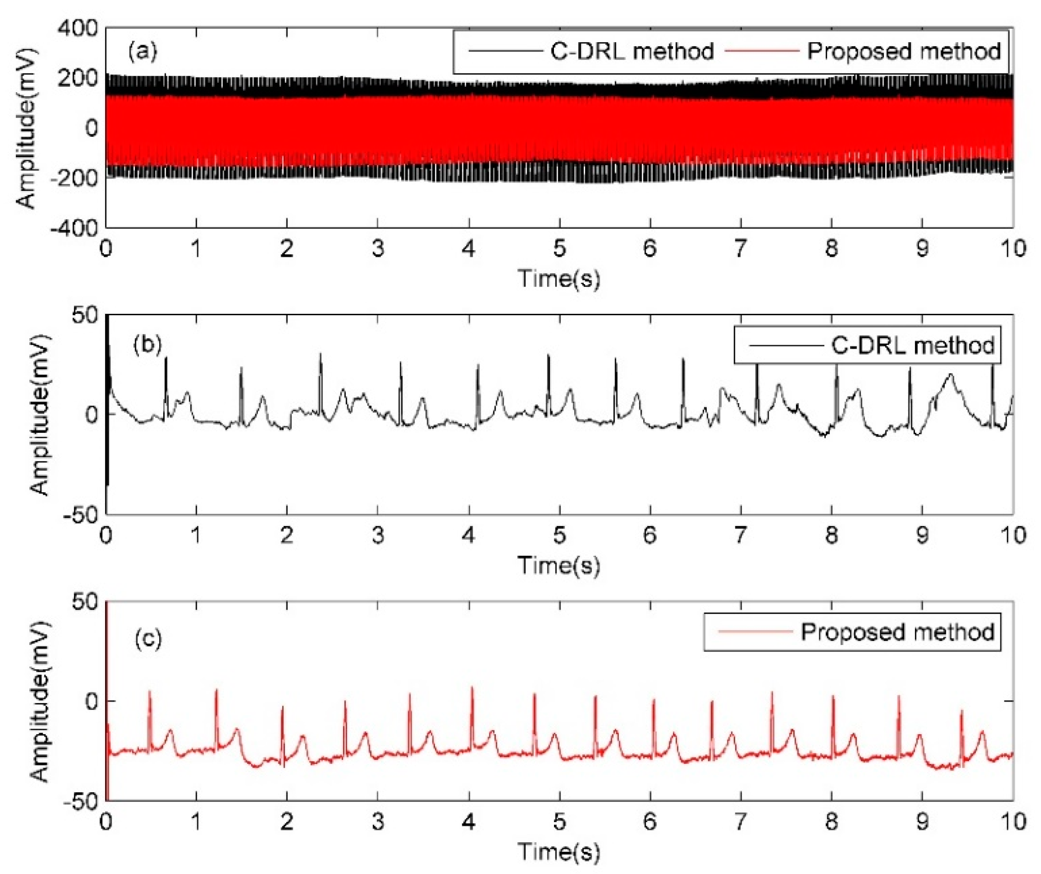
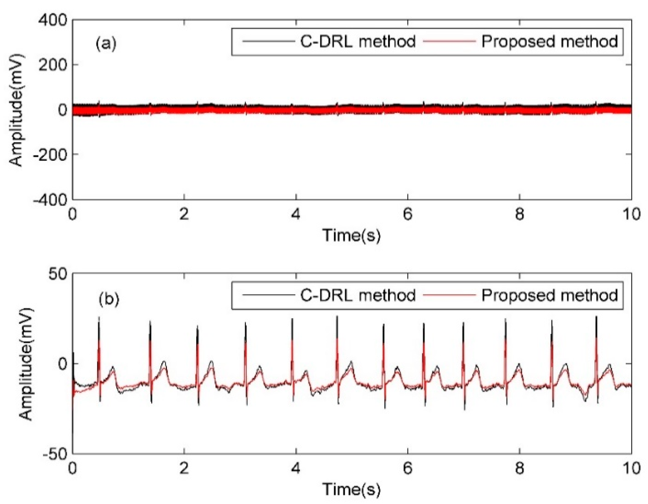
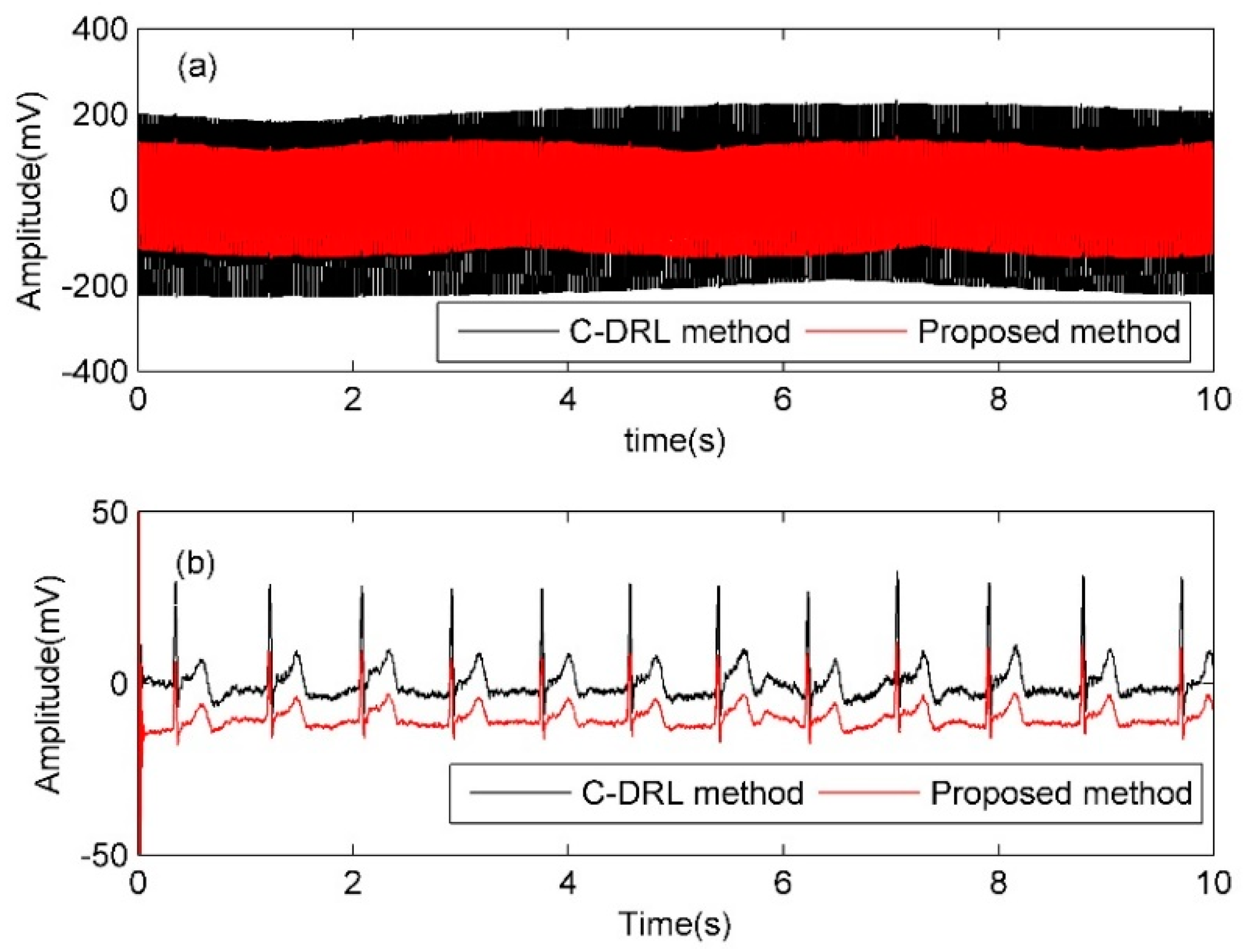
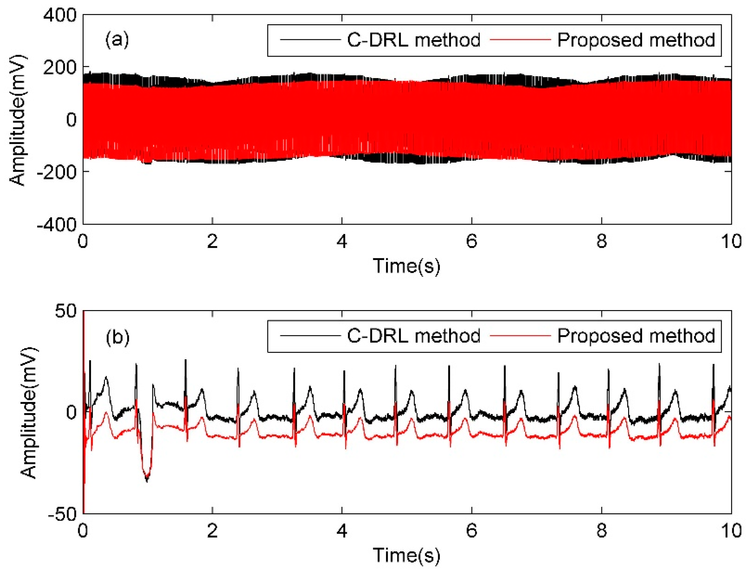
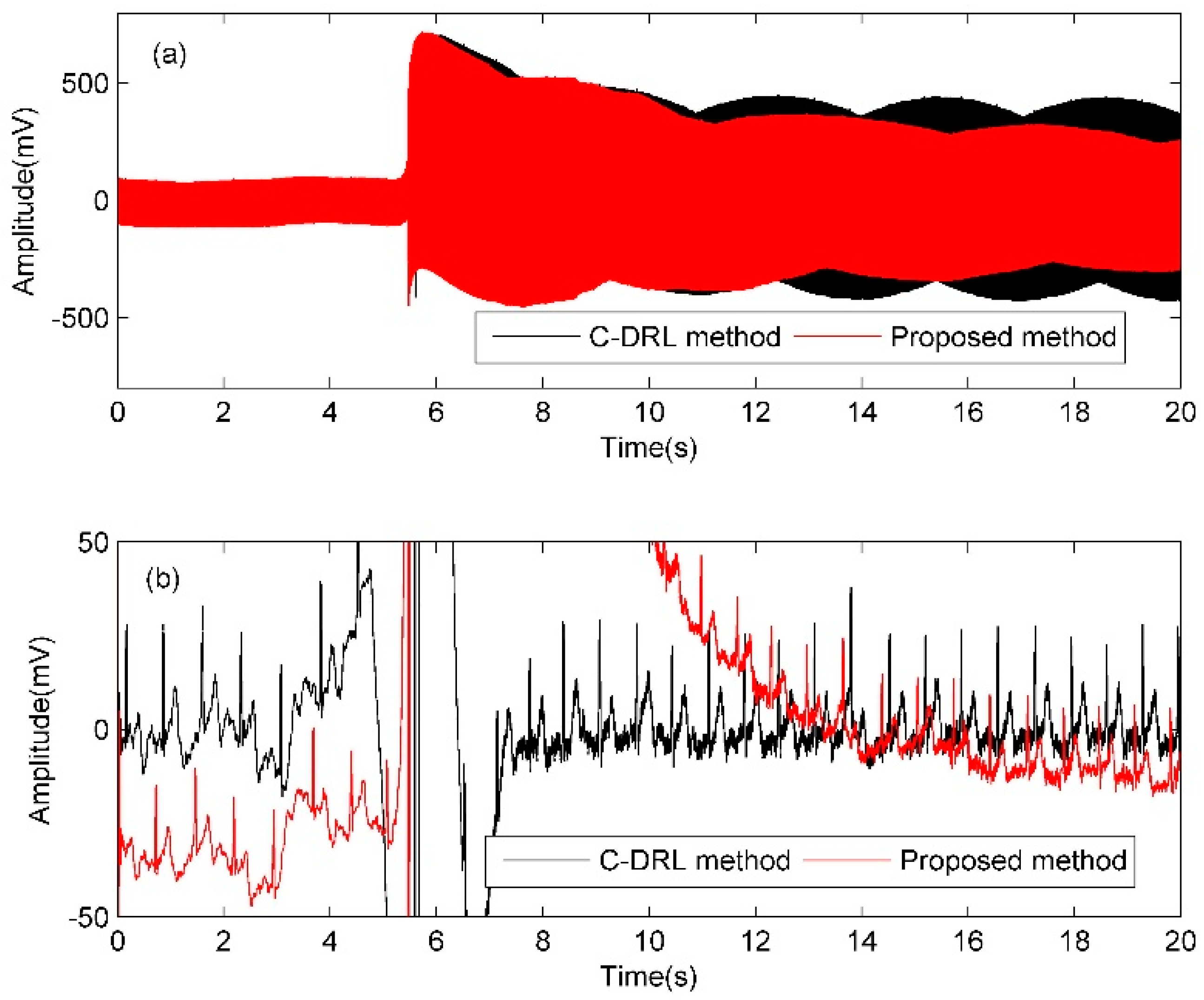
Schematic diagram of the dual-electrode bioelectric acquisition equipment for CMI suppression with the proposed noise neutralization method is shown in Figure 4, including two acquisition electrodes (ZE1 and ZE2 are the interface impedances) and corresponding front-ends A1 and A2 (ZA1 and ZA2 are the equivalent input impedances), a reference electrode (ZE3 is the interface impedance), and corresponding front-end A3 (ZA3 is the equivalent input impedance) and processing circuits. The processing circuits include a 50 Hz band-pass filter, two variable gain amplifiers (k1 and k2 are the gains), a micro control unit (MCU), an analog to digital converter (ADC), and a differential amplifier. In addition, the parameters explanations (VP, VCM, V’CM, CP, CB, and CS) are the same with that in Figure 1. The dotted line area is the neutral part, which uses the reference electrode and a 50 Hz band-pass filter to obtain the CMI of the human body and adapts the gains k1 and k2 to vary the CMI amplitude to the input ends of the differential amplifier in order to neutralize the CMI from two acquisition electrodes and achieve the minimum CMI output of the differential amplifier. It should be noted that the signal from the acquisition electrode will be attenuated by two cascading resistors ZM and ZN. Small attenuation requires large ratio of ZN to ZM. In the following analysis, the ratio of ZN to ZM is set as 9.
Figure 5 is the equivalent circuit model of the proposed neutralization method.
According to Kirchhoff’s current law, the CMI of the organism relative to signal ground V’CM, and the outputs of the front-ends VOA and VOB can be expressed as
V CM = Z B + Z S Z B Z P [ 1 Z P + 1 Z B + 1 A Z E 1 + 1 B Z E 2 + 1 C Z E 3 ] V P ,
V OA = Z N 1 Z M 1 + Z N 1 ( A + Z S Z B ) + Z M 1 Z M 1 + Z N 1 k 1 ( C + Z S Z B ) Z P [ 1 Z P + 1 Z B + 1 A Z E 1 + 1 B Z E 2 + 1 C Z E 3 ] V P ,
V OB = Z N 2 Z M 2 + Z N 2 ( B + Z S Z B ) + Z M 2 Z M 2 + Z N 2 k 2 ( C + Z S Z B ) Z P [ 1 Z P + 1 Z B + 1 A Z E 1 + 1 B Z E 2 + 1 C Z E 3 ] V P ,
A = Z A 1 Z B Z E 1 Z S Z A 1 Z B + Z E 1 Z B , B = Z A 2 Z B Z E 2 Z S Z A 2 Z B + Z E 2 Z B , C = Z A 3 Z B Z E 3 Z S Z A 3 Z B + Z E 3 Z B
As can be seen from (17)–(19), the common component of VOA and VOB can be reduced to 0 by adjusting the gains k1 and k2 to optimal values, and the CMI will be suppressed fully. The optimal k1 and k2 can be expressed as koptimal-1 and koptimal-2 by (20) and (21).
k optimal - 1 = Z N 1 Z M 1 Z A 1 ( Z A 3 + Z E 3 ) Z A 3 ( Z A 1 + Z E 1 ) ,
k optimal - 2 = Z N 2 Z M 2 Z A 2 ( Z A 3 + Z E 3 ) Z A 3 ( Z A 2 + Z E 2 ) ,
Under the situation that the neutralizing resistances ZN1, ZN2, ZM1, ZM2 and the equivalent input impedances ZA1, ZA2, ZA3 are definite values, koptimal-1 and koptimal-2 are only related to ZE1, ZE2, and ZE3 according to (20) and (21). The PDMC output of the differential amplifier can be expressed as (22), which shows that ∆VO is related to the impedance mismatch coefficient α of the electrode interface, the area ratio β of the acquisition electrode to the reference electrode, and the gain difference |∆k|. It should be noted that there is an optimal ∆k, defined ∆koptimal, can still make ∆VO be equal to 0 even if k1 and k2 cannot satisfy (20) and (21).
Δ V O = | Z N 1 Z M 1 + Z N 1 ( A B ) + Z M 1 Z M 1 + Z N 1 Δ k ( C + Z S Z B ) Z P [ 1 Z P + 1 Z B + 1 A Z E 1 + 1 B Z E 2 + 1 C Z E 3 ] | V P , Δ k = k 1 k 2
The performance comparison between C-DRL method and proposed noise neutralization method is shown in Figure 6, where the blue surface represents C-DRL method with β being 1 (the area of the acquisition electrode is the same to that of the driving electrode), and the red surface represents the proposed method with β being 1, the violet surface represents C-DRL method with β being 1/30 (the area of driving electrode is 30 times of the area of acquisition electrode) and the yellow surface represents the proposed method with β being 20 (the area of acquisition electrode is 20 times of the area of reference electrode). Considering k less than 0, |k| and |∆k| have been replaced by −k and ∆k respectively to unify the coordinate axes of the chart.
When the impedance mismatch coefficient α exists, ∆k in a certain range of the proposed method can obtain a smaller PDMC than that of C-DRL method. Even at the case of β being 1/30 for C-DRL method and β being 1 for proposed method, this conclusion can still be reached. Moreover, for the proposed method, the range of ∆k can be larger for β being 20 than that for β being 1, which means the proposed method is more effective than that of the C-DRL method, especially for small area of the reference electrode.

3. Experiments

The circuit system for the proposed neutralization method is implemented with two-board components, as shown in Figure 7, where the left side is the acquisition motherboard and the right side is the noise neutralization board. In the acquisition motherboard, the front-end is designed according to the proposed structure in reference [31], the integrated analog to digital converter ADS1298 with 24-bit resolution is selected as the differential amplifier, and the microcontroller MSP430F5528 is used to sample the data from ADS1298 and transform the data thorough the series port to the application in the computer. In the noise neutralization board, the ratio of ZN to ZM is set as 2 (ZN being10 kΩ and ZM being 5.1 kΩ) for easy resistance selection and the programmable resistor MAX5496 (10 kΩ, 1024 taps) is used to obtain high precision gain to meet the requirement of koptimal. It should be noted that the method for searching the optimal value adopted in this paper is dichotomy, which has three main steps. In the first step, the initial values of k1 and k2 are set respectively by controlling the taps of variable programmable resistors and the initial amplitudes of VOA and VOB are measured by the channel 2 and channel 3 of ADS1298, as shown in Figure 7. In the second step, the values of k1 and k2 are set to the median of the initial ranges and the amplitudes of VOA and VOB are measured again. In the third step, the values of k1 and k2 are reset according to the amplitudes of VOA and VOB measured in the previous two steps. These three steps will be repeated until the amplitudes of VOA and VOB are minimized. Applying the method, koptimal can be approximated and the amplitude of ∆VO can be reduced effectively.
Figure 8 is the comparison of the frequency response characteristics between the acquisition system with C-DRL method and the acquisition system with the proposed method. They have similar frequency response characteristics for using the same configuration of the acquisition front-end.
CMRR performance comparison between C-DRL method and the proposed method under different simulated impedance mismatch is shown in Table 1, where two input signals with same phase and different amplitude are used to simulate the electrode interface impedance mismatch. For α being 0, CMRRs for two methods are both about 90 dB. For α being 20%, CMRR for the proposed method can also achieve 90 dB by adjusting the gains k1 and k2 to optimal values, which means that the proposed method can suppress PDMC caused by the electrode mismatch effectively. However, for α being 20%, CMRR for C-DRL method is only 14.4 dB with the lack of feedback and may be improved with the closed-loop feedback. Therefore, the experiments with C-DRL method and the proposed neutralization method for human body ECG acquisition are carried out for further performance comparison.
Figure 9 shows the devices and bandage electrodes for simultaneously human ECG acquisition with the C-DRL method and the proposed method. The blue marks the device and the electrodes with C-DRL method, and the red marks the device and the electrodes with the proposed method. The driving electrode D of C-DRL method and the reference electrode R of the proposed method have the same area and the dimensions are 3 × 4 cm. The areas of the acquisition electrodes P and N are designed according to the experiment requirements.
When two acquisition devices are used to acquire ECG signal from human body at the same time, CMI coupled on human body may be reduced by C-DRL method, thus affecting the performance of the proposed method. Therefore, two devices are used to acquire ECG signal at the same chest position independently. For C-DRL method, the value of k is −100. For the proposed method, the band-pass filter is designed with the center frequency being 50 Hz, the gain at the center frequency being 0 dB, and the quality factor being 5. The human test subject is the volunteer from our group, one male student aged 25 without known cardiac pathology.
Under static condition, the independent measurement results of human chest ECG acquisition with interface impedance match (α = 0, the areas of electrodes P and N are both 3 × 4 cm) are shown in Figure 10 for two methods, where both the original signal and the ECG signal processed with 50 Hz digital notch filter from the original signal are given, showing that both two methods can obtain high quality ECG signals independently.
Subsequently, the independent measurement results of human chest ECG acquisition with interface impedance mismatch are carried out by using the insulated plastic to stem and reduce the area of electrode N artificially and simulate the impedance mismatch (α = 20%, the area of electrode P is 3 × 4 cm and the area of electrode N is about 3 × 3.2 cm), as shown in Figure 11, where the original signal amplitude of the C-DRL method is about 406 mV, while that of the proposed method is about 276 mV.
According to the results of Figure 10 and Figure 11, the proposed method has similar performance to that of C-DRL method with electrode interface impedance match, while has better PDMC suppression ability than that of C-DRL method with electrode interface impedance mismatch.
Furthermore, in order to compare the performance of two methods at the same time, two devices are used to acquire ECG signal at the same time as shown in Figure 9. Similar to the steps of independent measurement mentioned above, under static condition, the simultaneous measurement results of human chest ECG acquisition with interface impedance match (α = 0, the areas of electrode P and electrode N is are both 3 × 4 cm) are shown in Figure 12 and the simultaneous measurement results of human chest ECG acquisition with interface impedance mismatch (α = 20%, simulated, the area of electrode P is 3 × 4 cm and the area of electrode N is about 3 × 3.2 cm) are shown in Figure 13.
According to the results of Figure 12, it can be concluded that the proposed method has similar performance to that of the C-DRL method with electrode interface impedance match. As shown in Figure 13, the original signal amplitude of the C-DRL method is about 405 mV, while the original signal amplitude of the proposed method is about 249 mV, which shows the proposed method has better PDMC suppression performance in the case of electrode interface impedance mismatch.
When the areas of electrodes P and N are the same, ECG measurements of the two devices at the same time with small amplitude swing of upper limb are shown in Figure 14, where the performances of two methods are alike for similar amplitudes of two original signals.
In order to clearly observe the electrode interface impedance mismatch caused by body motion, the upper limb stays still first, then rotates to one side substantially, and then stays still again. The simultaneous measurement results are shown in Figure 15, where two methods can both acquire clear ECG signals for the upper limb being still and the performances of two methods are degraded by the upper limb rotation. This can be explained in that the upper limb rotation leads to the electrode interface impedance mismatch, which causes the increase of PDMC. For C-DRL method, the amplitude of the original signal is about 157.5 mV before the upper limb rotation, and is about 838 mV after the upper limb rotation. For the proposed method, the amplitude of the original signal is about 190.4 mV before the upper limb rotation, and is about 530.1 mV after the upper limb rotation. The upper limb rotation causes 12.7 dB interference increase for C-DRL method, and about 5.0 dB interference increase for the proposed method, which also shows that the proposed method has better PDMC suppression ability in the case of the electrode interface impedance mismatch.

4. Discussion and Conclusions

For non-contact bioelectrical acquisition, a new interference suppression method, named ‘noise neutralization method’, is proposed in this paper. Compared with C-DRL or DRL method, the proposed method can effectively reduce the area of the driving electrode, and has a stronger ability to suppress interference, especially for the situation of electrode interface impedance mismatch caused by body motion.
Firstly, the performance of C-DRL method for non-contact acquisition is analyzed using the equivalent circuit model, which shows that interference suppression degrades with the decrease of the gain of the inversion amplifier and the area of driving electrode in the case of the interface impedance mismatch of the acquisition electrode. Therefore, a noise neutralization method is proposed to suppress CMI and PDMC for non-contact bioelectrical acquisition by applying the reference electrode and a 50 Hz band-pass filter to obtain the CMI of the human body and adapting the gain k1 and k2 to neutralize the CMI input of two acquisition electrodes and achieve the minimum CMI output. The proposed method is characterized with that there is an optimal gain to achieve the minimum interference output whatever for the electrode interface impedance mismatch and is more effective for the smaller reference electrode area.
Subsequently, non-contact ECG acquisition devices based on C-DRL method and proposed method are designed to verify the performance of the proposed method. From the experiment results, it can be concluded that the proposed method has similar performance to that of the C-DRL method with electrode interface impedance match, while it has better PDMC suppression ability using a smaller reference electrode area and a smaller gain. This is the outstanding characterization of the proposed method. In general, the proposed method is an effective method to suppress interference CMI and PDMC under the situation of limited electrode area and unavoidable body motion.
It should be noted that the optimization method for adapting the gains k1 and k2 to optimal values is dichotomous in this paper, it is an effective method but its adapting time is not enough fast to suppress PDMC caused by strong body motion. Moreover, the variable gain amplifier with high programmable precision is required to obtain the optimal k, which may create complexity of the circuit structure.
In the future, a more effective adapting method will be studied to reduce the adapting time and the circuit structure will be improved for wearable applications.

Author Contributions

Conceptualization, L.Z.; Data curation, L.Z.; Funding acquisition, L.Z. and F.Y.; Investigation, Y.T. and R.C.; Project administration, L.Z. and F.Y.; Software, Y.T. and R.C.; Writing—original draft, Y.T. and R.C.; Writing—review and editing, L.Z. and F.Y. All authors have read and agreed to the published version of the manuscript.

Funding

This research was supported by National Key R&D Program of China (no. 2016YFA0202102) and National Nature Science Foundation Program of China (no. 11304152 and 61571376).

Conflicts of Interest

The authors declare no conflict of interest.

Abbreviations

ADCAnalog to digital converter
Ag/AgClSilver/silver chloride
C-DRLCapacitive driven-right-leg
CMICommon mode interference
CMRRCommon mode rejection ratio
DRLDriven-right-leg
ECGElectrocardiography
MCUMicro control unit
PDMCPseudo difference mode components

References

  1. Spinelli, E.; Haberman, M. Insulating electrodes: A review on biopotential front ends for dielectric skin-electrode interfaces. Physiol. Meas. 2010, 31, 183–198. [Google Scholar] [CrossRef] [PubMed]
  2. Leicht, L.; Eilebrecht, B.; Weyer, S.; Leonhardt, S.; Teichmann, D. Closed-loop control of humidification for artifact reduction in capacitive ECG measurements. IEEE Trans. Biomed. Circuits Syst. 2017, 11, 300–313. [Google Scholar] [CrossRef]
  3. Meziane, N.; Webster, J.G.; Attari, M.; Nimunkar, A.J. Dry electrodes for electrocardiography. Physiol. Meas. 2013, 34, 47–69. [Google Scholar] [CrossRef] [PubMed]
  4. Boehm, A.; Yu, X.; Neu, W.; Leonhardt, S.; Teichmann, D. A Novel 12-Lead ECG T-Shirt with Active Electrodes. Electronics 2016, 5, 75. [Google Scholar] [CrossRef] [Green Version]
  5. Acar, G.; Ozturk, O.; Golparvar, A.J.; Elboshra, T.A.; Böhringer, K.; Yapici, M.K. Wearable and Flexible Textile Electrodes for Biopotential Signal Monitoring: A review. Electronics 2019, 8, 479. [Google Scholar] [CrossRef] [Green Version]
  6. Sun, Y.; Yu, X.B. Capacitive biopotential measurement for electrophysiological signal acquisition: A review. IEEE Sens. J. 2016, 16, 2832–2853. [Google Scholar] [CrossRef]
  7. Oehler, M.; Ling, V.; Melhorn, K.; Schilling, M. A multichannel portable ECG system with capacitive sensors. Physiol. Meas. 2008, 29, 783–793. [Google Scholar] [CrossRef]
  8. Wannenburg, J.; Malekian, R.; Hancke, G.P. Wireless capacitive based ECG sensing for feature extraction and mobile health monitoring. IEEE Sens. J. 2018, 18, 6023–6032. [Google Scholar] [CrossRef] [Green Version]
  9. Yang, B.; Dong, Y.; Hou, Z.; Xue, X. Simultaneously capturing electrocardiography and impedance plethysmogram signals from human feet by capacitive coupled electrode system. IEEE Sens. J. 2017, 17, 5654–5662. [Google Scholar] [CrossRef]
  10. Chi, Y.M.; Jung, T.; Cauwenberghs, G. Dry-contact and noncontact biopotential electrodes: Methodological review. IEEE Rev. Biomed. Eng. 2010, 3, 106–119. [Google Scholar] [CrossRef] [Green Version]
  11. Tomasini, M.; Benatti, S.; Milosevic, B.; Farella, E.; Benini, L. Power line interference removal for high-quality continuous biosignal monitoring with low-power wearable devices. IEEE Sens. J. 2016, 16, 3887–3895. [Google Scholar] [CrossRef] [Green Version]
  12. Sullivan, T.J.; Deiss, S.R.; Jung, T.P.; Cauwenberghs, G. A brain-machine interface using dry-contact, low-noise EEG sensors. In Proceedings of the IEEE International Symposium on Circuits and Systems (ISCAS 2008), Seattle, WA, USA, 18–21 May 2008; pp. 1986–1989. [Google Scholar]
  13. Kim, K.K.; Park, K.S. Effective coupling impedance for power line interference in capacitive-coupled ECG measurement system. In Proceedings of the International Conference on Information Technology and Applications in Biomedicine (ITAB 2008), Shenzhen, China, 30–31 May 2008; pp. 256–258. [Google Scholar]
  14. Lim, Y.G.; Kim, K.K.; Park, K.S. ECG measurement on a chair without conductive contact. IEEE Trans. Biomed. Eng. 2006, 53, 956–959. [Google Scholar] [PubMed]
  15. Lim, Y.G.; Chung, G.S.; Park, K.S. Capacitive driven-right-leg grounding in indirect-contact ECG measurement. In Proceedings of the Annual International Conference of the IEEE Engineering in Medicine and Biology (EMBS 2010), Buenos Aires, Argentina, 31 August–4 September 2010; pp. 1250–1253. [Google Scholar]
  16. Kim, K.K.; Lim, Y.G.; Park, K.S. Common mode noise cancellation for electrically non-contact ECG measurement system on a chair. In Proceedings of the IEEE Engineering in Medicine and Biology 27th Annual Conference (EMBS 2005), Shanghai, China, 17–18 January 2006; pp. 5881–5883. [Google Scholar]
  17. Pallas-Areny, R. On the reduction of interference due to common mode voltage in two-electrode biopotential amplifiers. IEEE Trans. Biomed. Eng. 1986, 33, 1043–1046. [Google Scholar] [CrossRef] [PubMed]
  18. Winter, B.B.; Webster, J.G. Reduction of interference due to common mode voltage in biopotential amplifiers. IEEE Trans. Biomed. Eng. 1983, 30, 58–62. [Google Scholar] [CrossRef]
  19. Lee, K.; Lee, S.; Sim, K.; Kim, K.; Park, K.S. Noise reduction for non-contact electrocardiogram measurement in daily life. In Proceedings of the 36th Annual Computers in Cardiology Conference (CinC 2009), Park City, UT, USA, 13–16 September 2009; pp. 493–496. [Google Scholar]
  20. Guermandi, M.; Scarselli, E.F.; Guerrieri, R. A driving right leg circuit (DgRL) for improved common mode rejection in bio-potential acquisition systems. IEEE Trans. Biomed. Circuits Syst. 2016, 10, 507–517. [Google Scholar] [CrossRef] [Green Version]
  21. Steffen, M.; Aleksandrowicz, A.; Leonhardt, S. Mobile noncontact monitoring of heart and lung activity. IEEE Trans. Biomed. Circuits Syst. 2007, 1, 250–257. [Google Scholar] [CrossRef]
  22. Winter, B.B.; Webster, J.G. Driven-right-leg circuit design. IEEE Trans. Biomed. Eng. 1983, 30, 62–66. [Google Scholar] [CrossRef]
  23. Villegas, A.; McEneaney, D.; Escalona, O. Arm-ECG Wireless Sensor System for Wearable Long-Term Surveillance of Heart Arrhythmias. Electronics 2019, 8, 1300. [Google Scholar] [CrossRef] [Green Version]
  24. Ding, J.; Tang, Y.; Zhang, L.; Yan, F.; Gu, X.; Wu, R. A novel front-end design for bioelectrical signal wearable acquisition. IEEE Sens. J. 2019, 19, 8009–8018. [Google Scholar] [CrossRef]
  25. Xu, J.; Mitra, S.; Matsumoto, A.; Patki, S.; VanHoof, C.; Makinwa, K.A.A.; Yazicioglu, R.F. A wearable 8-channel active-electrode EEG/ETI acquisition system for body area networks. IEEE J. Solid-State Circuits 2014, 49, 2005–2016. [Google Scholar] [CrossRef] [Green Version]
  26. Sakuma, J.; Anzai, D.; Wang, J. Performance of human body communication-based wearable ECG with capacitive coupling electrodes. Healthc. Technol. Lett. 2016, 3, 222–225. [Google Scholar] [CrossRef] [PubMed] [Green Version]
  27. Serteyn, A.; Vullings, R.; Meftah, M.; Bergmans, J.W.M. Motion artifacts in capacitive ECG measurements: Reducing the combined effect of DC voltages and capacitance changes using an injection signal. IEEE Trans. Biomed. Eng. 2015, 62, 264–273. [Google Scholar] [CrossRef] [PubMed] [Green Version]
  28. Yoon, S.W.; Min, S.D.; Yun, Y.H.; Lee, S.; Lee, M. Adaptive motion artifacts reduction using 3-axis accelerometer in e-textile ECG measurement system. J. Med. Syst. 2008, 32, 101–106. [Google Scholar] [CrossRef] [PubMed]
  29. Rodrigues, R.; Couto, P. A neural network approach to ECG denoising. arXiv 2012, arXiv:1212.5217. [Google Scholar]
  30. AAMI; ANSI. Diagnostic Electrocardiographic Devices; Standard ANSI/AAMI EC11; AAMI: Washington, DC, USA, 2007. [Google Scholar]
  31. Wu, R.; Tang, Y.; Li, Z.; Zhang, L.; Yan, F. A novel high input impedance front-end for capacitive biopotential measurement. Med. Biol. Eng. Comput. 2018, 56, 1343–1355. [Google Scholar] [CrossRef] [PubMed]
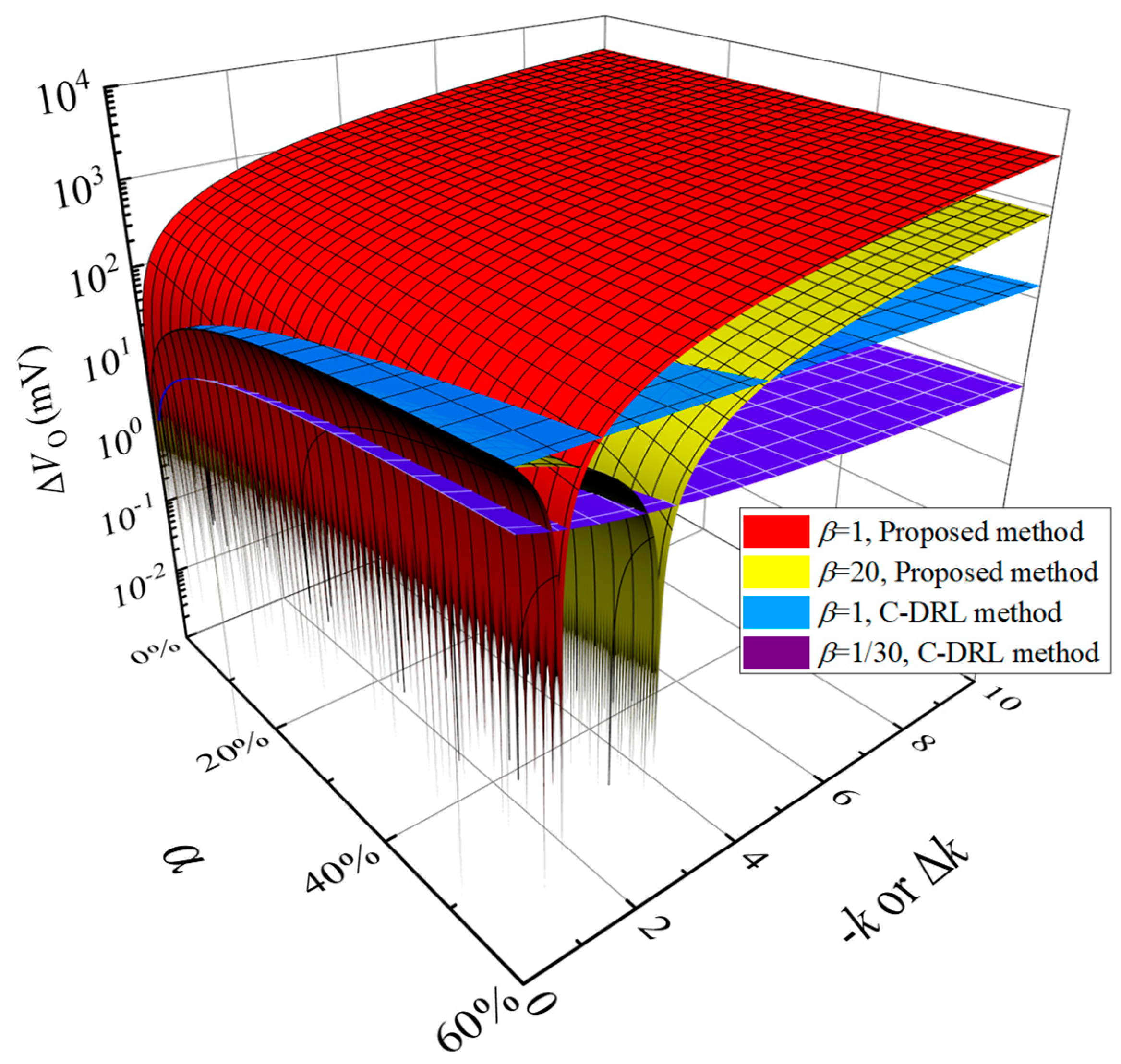
Figure 1. Equivalent circuit model of the dual-electrode bioelectric acquisition equipment for CMI suppression with C-DRL method.
Electronics 09 00293 g001
Figure 2. PDMC ∆VO as function of the impedance mismatch coefficient of two acquisition electrodes with different areas of the driving electrode for C-DRL method, where the value of |k| is 100 according to the setting in [16]. It increases with the increase of the impedance mismatch coefficient α for constant β and |k|. PDMC can be further suppressed by the decrease of β for constant |k|.
Electronics 09 00293 g002
Figure 3. PDMC ∆VO as functions of the gain of the inversion amplifier and the impedance mismatch coefficient of two acquisition electrodes for C-DRL method. It increases with the increase of the impedance mismatch coefficient α for constant β and |k|, decreases with the increase of |k| in a certain range and is almost unchanged for |k| larger than a certain value. PDMC can also be further suppressed by the decrease of β for constant |k|.
Electronics 09 00293 g003
Figure 4. Schematic diagram of the dual-electrode bioelectric acquisition equipment for CMI suppression with the proposed noise neutralization method.
Electronics 09 00293 g004
Figure 5. Equivalent circuit model of the dual-electrode bioelectric acquisition equipment for CMI suppression with the proposed noise neutralization method.
Electronics 09 00293 g005
Figure 6. The performance comparison between C-DRL method and the proposed noise neutralization method, where the red and yellow surfaces represent the proposed method with β being 1 and 20, respectively. The blue and violet surfaces represent the C-DRL method with β being 1 and 1/30, respectively. When the impedance mismatch coefficient α exists, ∆k in a certain range of the proposed method can obtain a smaller PDMC than that of C-DRL method and there always exists a certain smaller optimal gain to minimize PDMC. Theoretically, under the same conditions, the proposed method has better PDMC suppression with a larger β (smaller reference electrode area) and a smaller gain (compared with the typical driving gain of C-DRL method).
Electronics 09 00293 g006
Figure 7. Circuit system for the proposed neutralization method, (a) the acquisition motherboard, (b) the noise neutralization board.
Electronics 09 00293 g007
Figure 8. Comparison of the frequency response between the acquisition system with C-DRL method and the acquisition system with proposed method.
Electronics 09 00293 g008
Figure 9. Devices and bandage electrodes for human body ECG acquisition using the C-DRL method and the proposed method.
Electronics 09 00293 g009
Figure 10. Independent measurement results of human chest ECG acquisition with interface impedance match under static condition, (a) time-domain waveform of original signal, (b) ECG signal of C-DRL method processed by software notch, (c) ECG signal of proposed method processed by software notch.
Electronics 09 00293 g010
Figure 11. Independent measurement results of human chest ECG acquisition with interface impedance mismatch under static condition, (a) time-domain waveform of original signal, (b) ECG signal of C-DRL method processed by software notch, (c) ECG signal of the proposed method processed by software notch.
Electronics 09 00293 g011
Figure 12. Simultaneous measurement results of human chest ECG acquisition with interface impedance match under static condition, (a) time-domain waveform of original signal, (b) ECG signal processed by software notch.
Electronics 09 00293 g012
Figure 13. Simultaneous measurement results of human chest ECG acquisition with interface impedance mismatch under static condition, (a) time-domain waveform of original signal, (b) ECG signal processed by software notch.
Electronics 09 00293 g013
Figure 14. Simultaneous measurement results of human chest ECG acquisition with small amplitude swing of upper limb, (a) time-domain waveform of original signal, (b) ECG signal processed by software notch.
Electronics 09 00293 g014
Figure 15. Simultaneous measurement results of human chest ECG acquisition for the process of the upper being still, rotating to one side substantially and being still again, (a) time-domain waveform of original signal, (b) ECG signal processed by software notch.
Electronics 09 00293 g015
Table 1. CMRR comparison of circuits using proposed method and C-DRL method.
Simulation of Electrode MismatchInput Signal Amplitude of Electrode 1CMRR
C-DRL MethodProposed Method
α = 0P: 500 mV
N: 500 mV
91.45 dB90.36 dB
α = 20%P: 500 mV
N: 400 mV
14.40 dB 290.22 dB
1 The frequency of all input signal is 50 Hz. For the proposed method, the input signal amplitude of the reference electrode R is always 500 mV. 2 Due to the lack of negative feedback, this simulation value is lower than the actual value of C-DRL method.

