1. Introduction
Circuit breakers are used to protect loads from over-currents that flow in the event of an accident in the power transmission and distribution system. The types of circuit breakers installed are classified according to the capacity of the system, the amount of the over-current flowing in, and the medium protecting the arc generated during the interruption. Among them, molded case circuit breakers (MCCB) are mainly used in medium-power and low-power distribution systems, with a wide range of areas ranging from industrial environments to residential and light industrial environments. Up until now, the field of research on these circuit breakers has tended to be mainly experimental. J. W. McBride has experimentally studied the effect of separation velocity of contact on arc characteristics [
1]. J. Sekikawa et al. experimentally derived the relationship of voltage and current of breaking arc according to the materials of contact (Ag, Au, Cu and Ni) in the atmosphere pressure [
2]. In addition, experimental studies have been conducted on arc characteristics and at low voltage direct current [
3]. However, simulation studies have also been on the rise. Digpalsinh et al. studied the improvement of the repulsive force of the contacts in the MCCB [
4], and F Yang et al. studied the arc behavior in the circuit breaker by simulation, respectively [
5]. Studies on circuit breakers installed in DC distribution are being actively carried out. Most of the studies are on the breakers applied to DC grids or DC distribution systems [
6,
7,
8,
9,
10,
11], Ahmad M et al. dealt with hybrid circuit breakers that limit the fault current in the DC transmission line [
11]. In addition, not only mechanical and thermoelectric circuit breakers but also semiconductor-based circuit breakers are being studied [
12,
13].
In general, the interruption performance of the circuit breaker is represented by a voltage–time characteristic curve that indicates break time when the trip occurs depending on the amount of the incoming current. This indicates the interruption reliability to protect the load within the specified time-period when the over-current is inflowing. However, even if the circuit breaker is tripped normally, it is not possible to protect the load when the arc recurs due to re-ignition. Therefore, indicators are required to determine the interruption performance after the current-zero. In order to determine the interruption characteristics of the MCCB after the current-zero, the overall process of the blocking operation must be dealt with first. The MCCB consists of the sensing section, the driving section, and the arc-extinguishment section. When an over-current is introduced, the temperature of the bimetal in the sensing section increases, causing the starter in the driving section to operate. Afterwards, the operation of the driving section causes the separation of the fixed and moving electrodes of the arc-extinguishment section, and the arc is generated between the electrodes. At this time, the hot temperature and high-pressure arc between the electrodes generate hot gases in the arc-extinguishment section. The generated arc is moved to the splitter plate due to the arc runner and the pressure of hot gas, and repulsive force between electrodes. When the arc reaches the splitter plate, it loses energy through extension, cooling, and separation and is extinguished to current-zero. [
14].
During these interruption operations, if the hot gas generated by the arc is not properly emitted or the system recovery voltage is beyond the dielectric strength reduced by the hot gas, the re-ignition of the arc occurs. This re-ignition causes an accident that burns the load even though the circuit breaker is tripped normally. Re-ignition is closely related to the dielectric recovery strength between electrodes after discharge, and many studies have been conducted on this. Degui Chen [
15] experimentally identified the dielectric strength between the two electrodes according to the current amount through a simple circuit. J. J. Sena [
16,
17] conducted experimental studies on the dielectric strength and ablation according to the medium of the arc-extinguishment section. In this paper, several structures for improving the dielectric recovery voltage(DRV) of MCCB were proposed, and confirmed through experiment. In the previous study [
18,
19], the DRV curve was derived by experiment and the dielectric strength of the splitter plate that varies over time was studied. The initial slope of the DRV curve is dominated by the effect of the hot gas cooling effect, and by the second half, it is affected by the emission of residual hot gas within the arc-extinguishment section. Therefore, to improve the initial cooling effect of the splitter plate based on these characteristics, the material and composition of the plate were changed and the DRV was measured to verify the effect.
2. Theories of the Dielectric Recovery Voltage
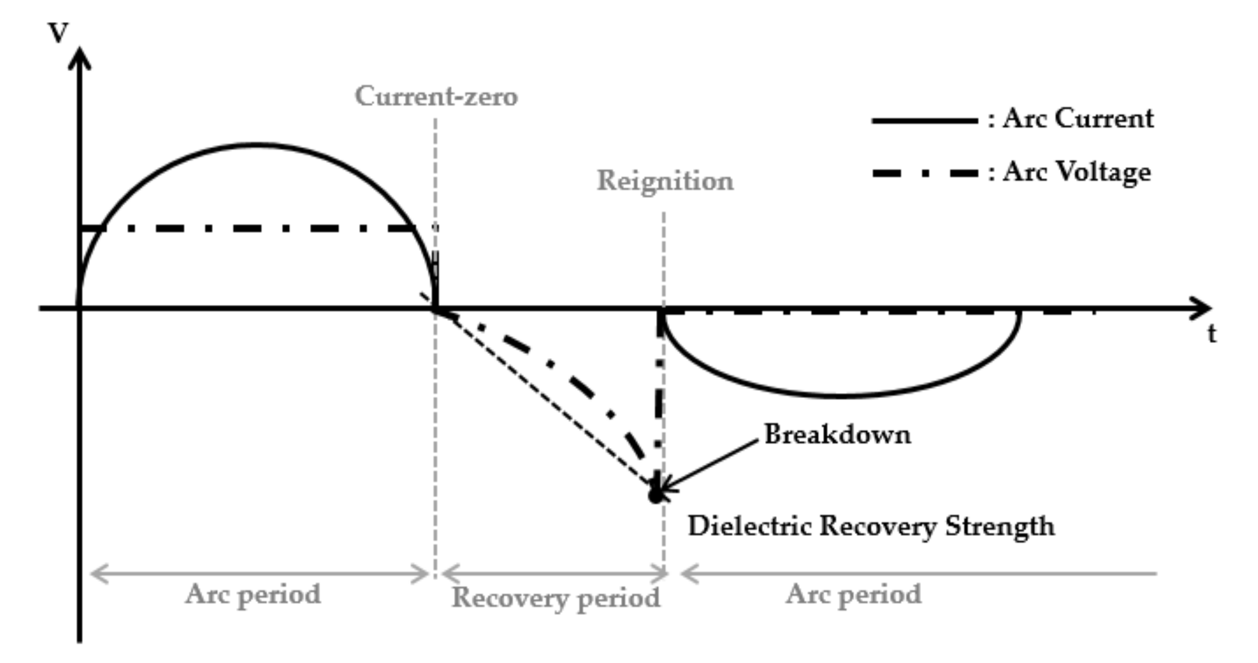
Typical dielectric recovery voltages are described as shown in
Figure 1. When the arc current flowing between the two electrodes breaks at the current-zero during the arc period, the dielectric strength between the electrodes gradually increases and recovers to the dielectric strength in the air. During this recovery period, if the voltage applied to the electrodes exceeds the dielectric strength between electrodes, the re-ignition will occur and the arc current flows again with second discharge.
In the interruption of the MCCB, hot gas is generated by the arc generated during contact separation, which causes the dielectric strength between the electrodes to decrease after the current-zero. Failure to interrupt over-currents by re-ignition damages the load even though the MCCB is operating normally. Therefore, by deriving the DRVs of these MCCBs, it is possible to evaluate the interruption performance by hot gas after the current-zero of the circuit breaker and increase the interruption reliability.
3. Experiment Studies
To measure the DRV of the MCCB, a measurement system is set and experiments are repeated. The measurement system requires an overcurrent source to trip the MCCB. In addition, the experimental setup should be configured to apply voltages between the electrodes faster than dielectric recovery of the circuit breaker after current-zero.
Figure 2 shows the system for measuring the DRV in this paper.
Here, Rec. is a rectifier, CS is a capacitor bank, L is an inductor for controlling over-current frequency, Thyr. is a thyristor, which is a semiconductor switch for applying over-current, and the gate driver is used for sending the operation signal to thyristor. R is a resistor and D is a diode for decreasing the return current. C0 is a capacitor for generating random re-ignition using its own capacitance value. The voltage is charged to the capacitor bank through transformer(TR) and rectifier(Rec). When the gate signal is applied to the thyristor, the generated over-current operates the MCCB. After the MCCB has tripped, charge C0 in the reverse direction and adjust the C0 value to make the charging time shorter than the dielectric recovery time between the MCCB electrodes in contact separation state to generate an arbitrary re-ignition. By repeating the above experimental process, which changes the charging time by adjusting the C0 value, the V–t curve of the DRV can be measured by recording the time and voltage. The DRV is measured by the oscilloscope via a high voltage probe at the voltages on both ends of the MCCB and C0. Using the oscilloscope’s trigger function, the voltage waveform in microseconds is clearly measurable, but one thing to consider in repeating the experiment is that sufficient rest periods are required between tests. If the following experiments are carried out in too short a time, the dielectric strength can be measured too high because the hot gas inside the arc chamber of the MCCB is not sufficiently exhausted. Therefore, sufficient time intervals and on–off operation of the circuit breaker are required between tests.
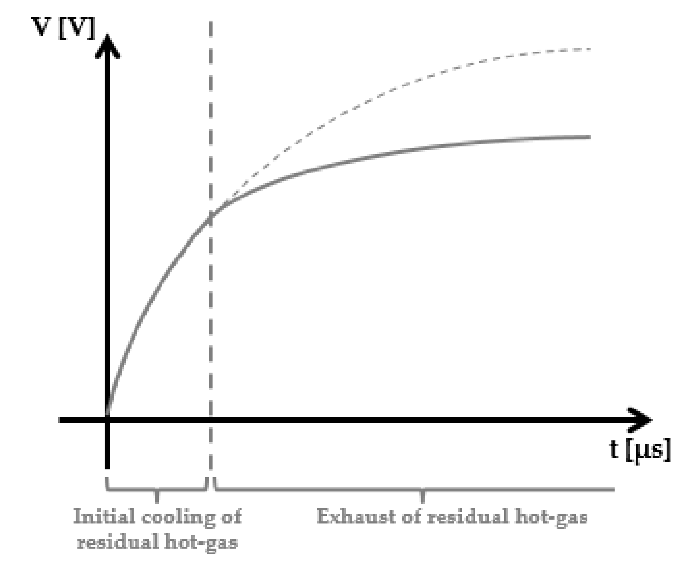
The typical curve of the DRV is shown in
Figure 3, and the inflection point of the slope appears. The role of the splitter plate for residual hot gas in each area is distinguished based on the corresponding inflection point. Cooling and adsorption of residual hot gas affects the slope of the initial curve, and exhaust of residual hot gas affects the slope of the latter curve [
19]. Thus, the structure and material of the splitter plate were changed to improve dielectric performance for hot gas after current-zero.
3.1. Results According to Materials of Splitter Plate
First, the material of the splitter plate was changed. In general, the splitter plate of the MCCB uses iron mixed with iron or other metals of trace amounts.
Table 1 shows the properties of iron and other metals at 20 degrees.
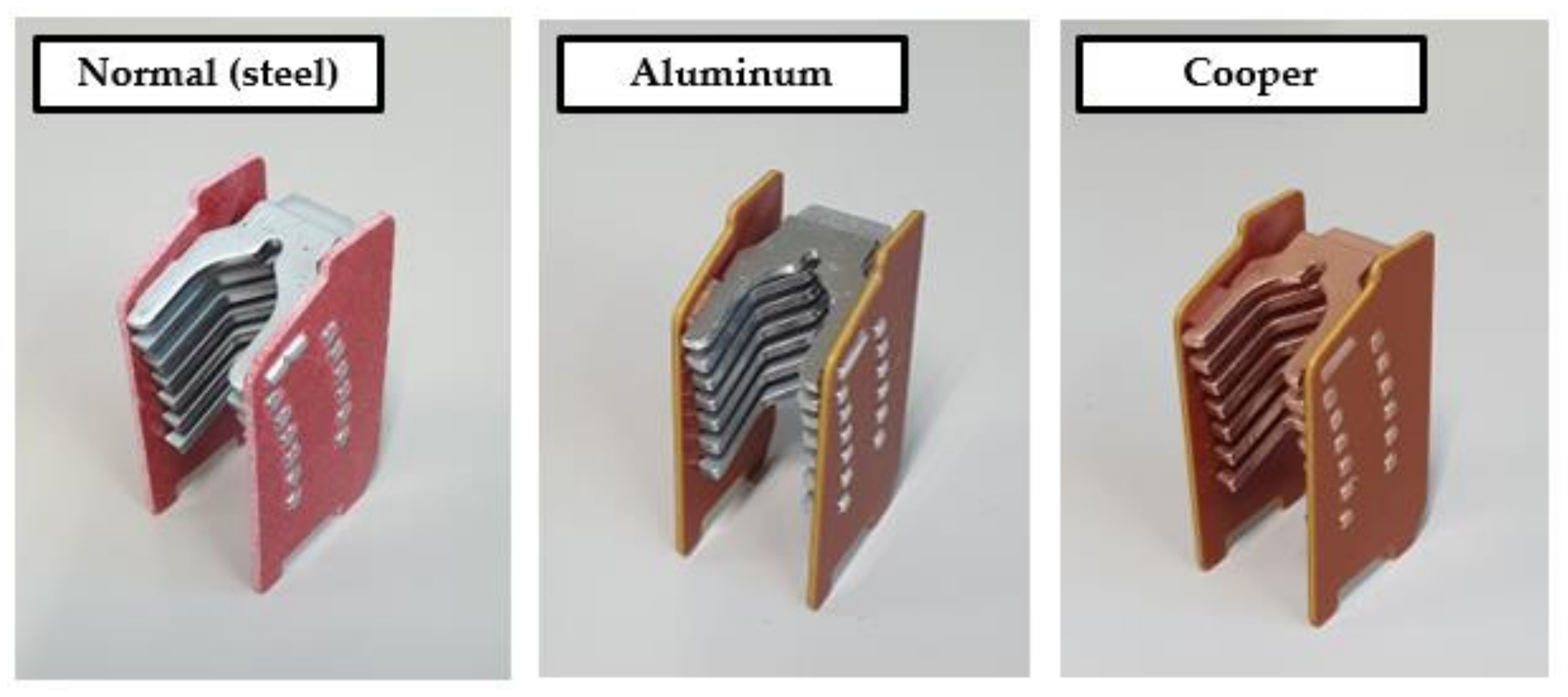
To compare the cooling effect of the splitter plate for the initial residual hot gas, the splitter plate was made with steel, aluminum, and copper, which is shown in
Figure 4. The thermal conductivity was lowered in the order of copper (320), aluminum (196), and steel (62).
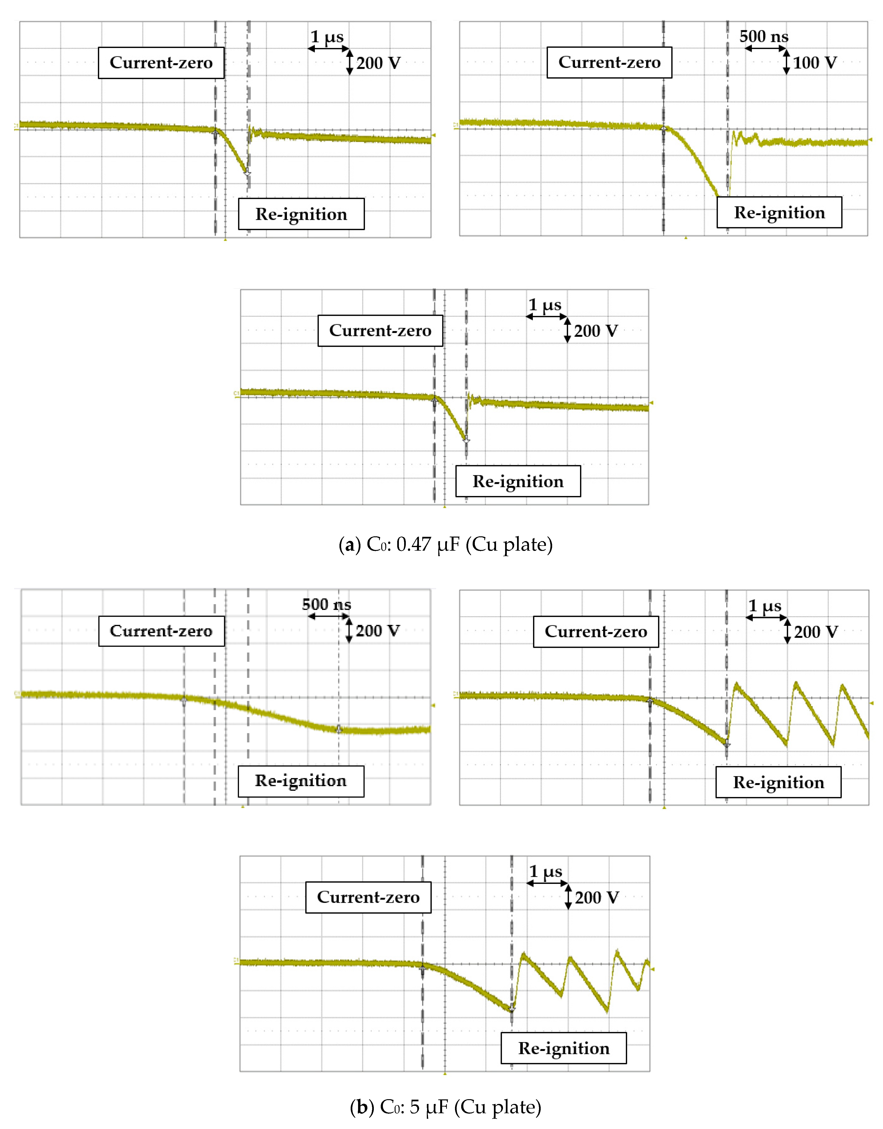
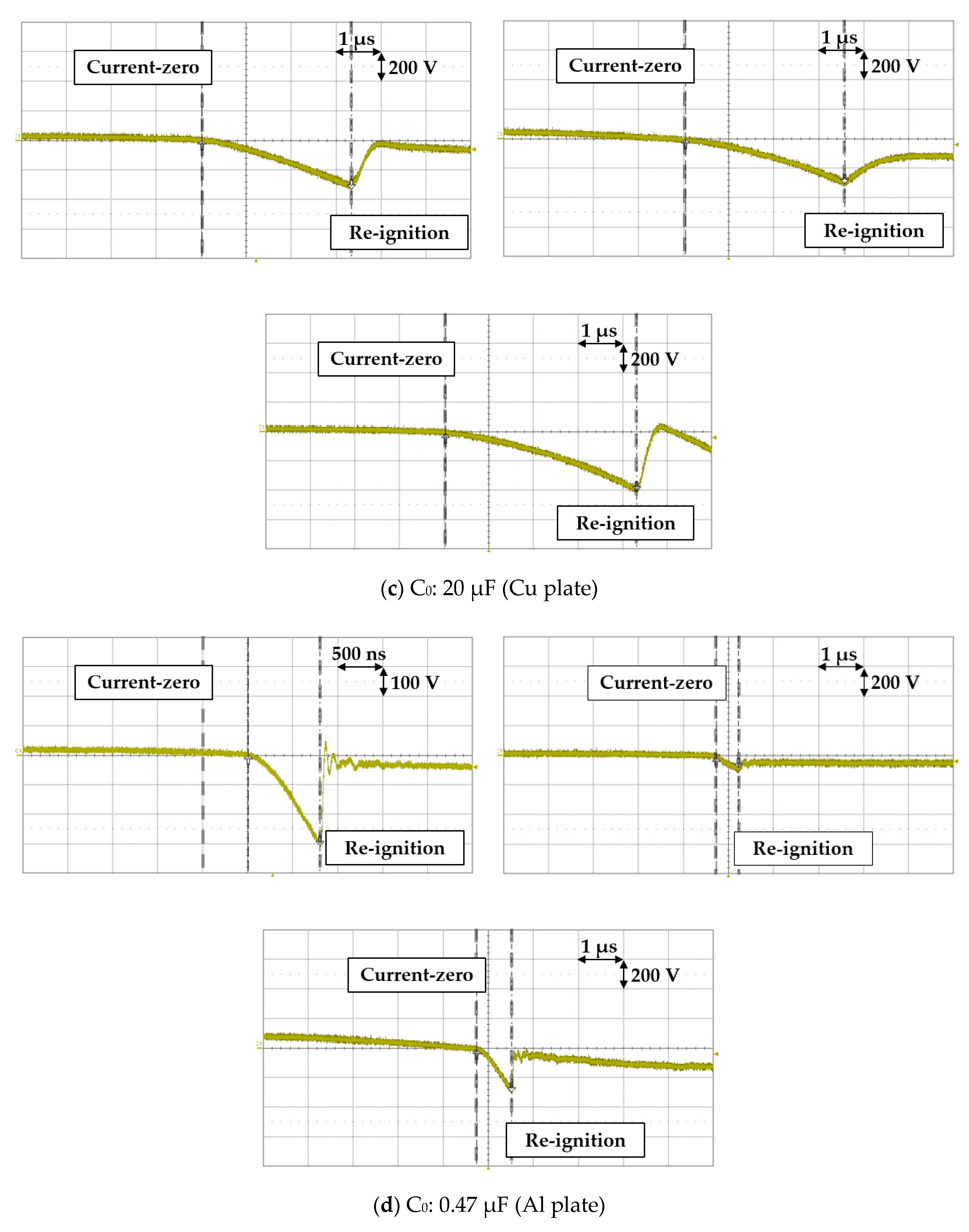
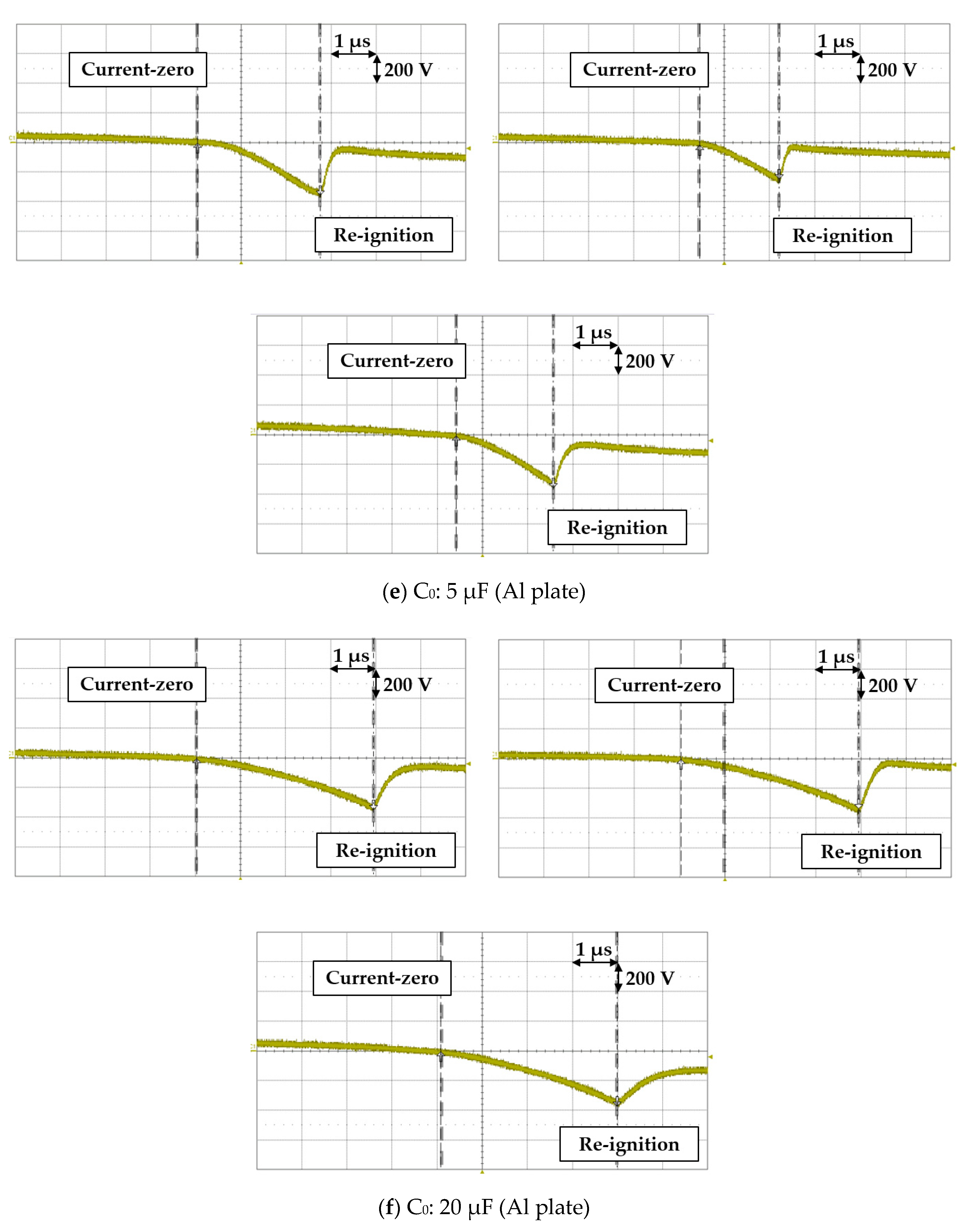
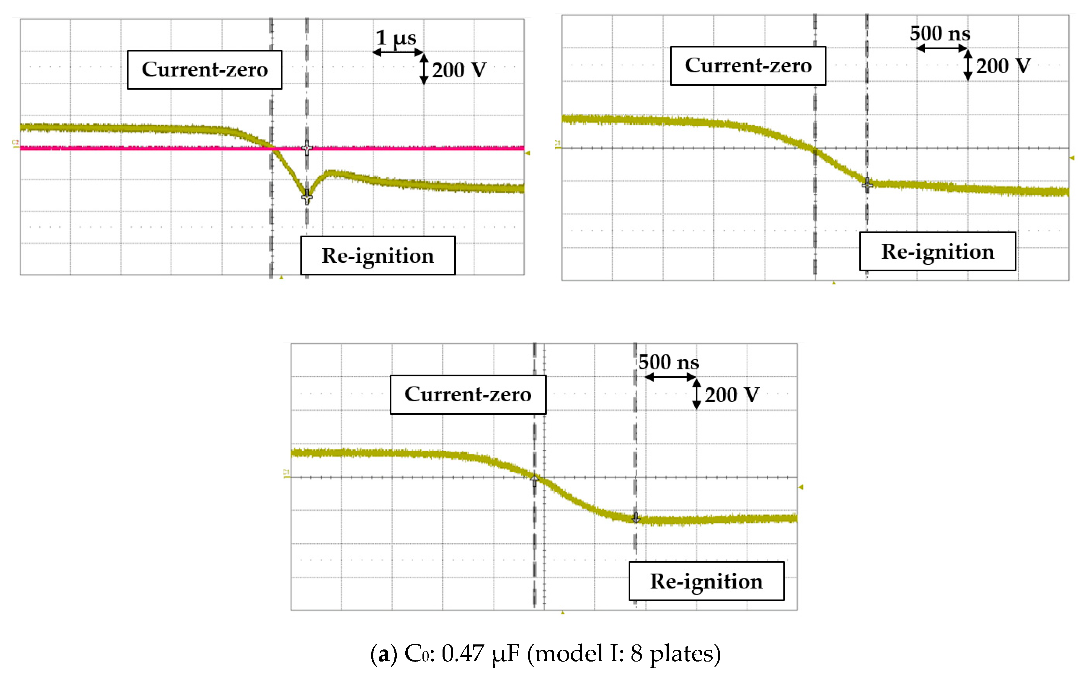
The experimental waveforms of aluminum and copper splitter plates are shown in
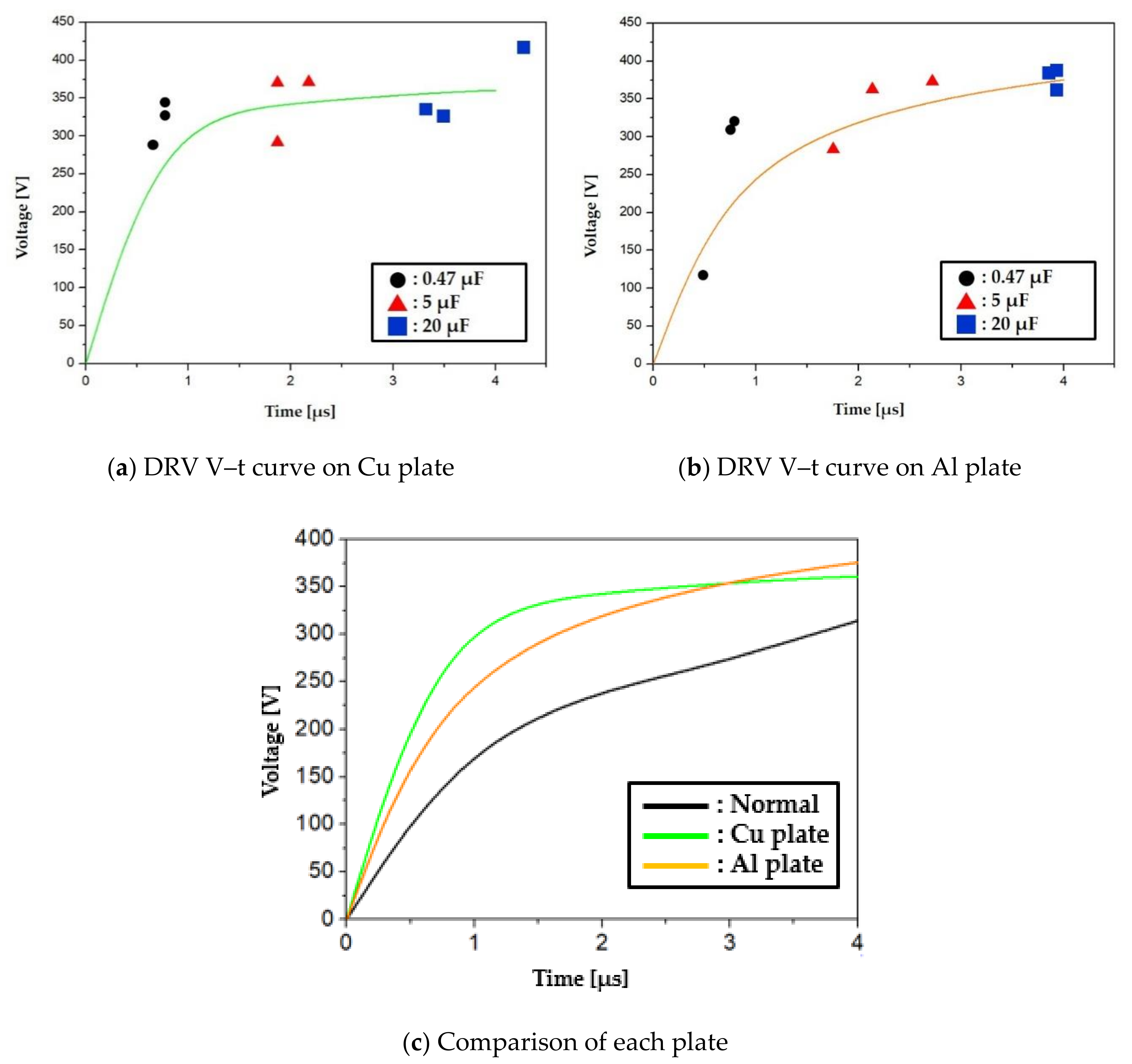
Figure 5, and the DRV V–t curves are shown in
Figure 6. The results of the experimental measurements are shown in
Table 2. The plate in the normal state that is subject to comparison consists of a steel, and the DRV V–t curve is used as a reference in the previous study [
18].
The waveform shown in
Figure 5a is the representative DRV waveform of this paper. In this waveform, the arc period moves to the recovery period after the current-zero, when the dielectric strength rises between electrodes. Re-ignition occurs when the charging voltage of C
0, which simulates the recovery voltage of the power system, exceeds the dielectric recovery voltage between electrodes. At this time, the arc period begins again. The second and third waveforms in
Figure 5b show waveforms with additional repetitive re-ignition after the initial re- ignition. This is considered to be caused by poor exhaust of residual hot gas between electrodes, or by insufficient consumption of the charged voltage at C
0. The first re-ignition point was used in the above situation.
As shown in the DRV V–t curve, the best initial dielectric recovery voltage is shown in the Cu plate, followed by the plate made of Al and the normal plate. This shows that the higher the thermal conductivity of the splitter plate material is, the better the cooling performance of the initial residual hot gas is. In these experiments, since the structure of each splitter plate is the same, no difference is shown in the slope of the latter curve affected by emission.
3.2. Results According to Structure of Splitter Plate
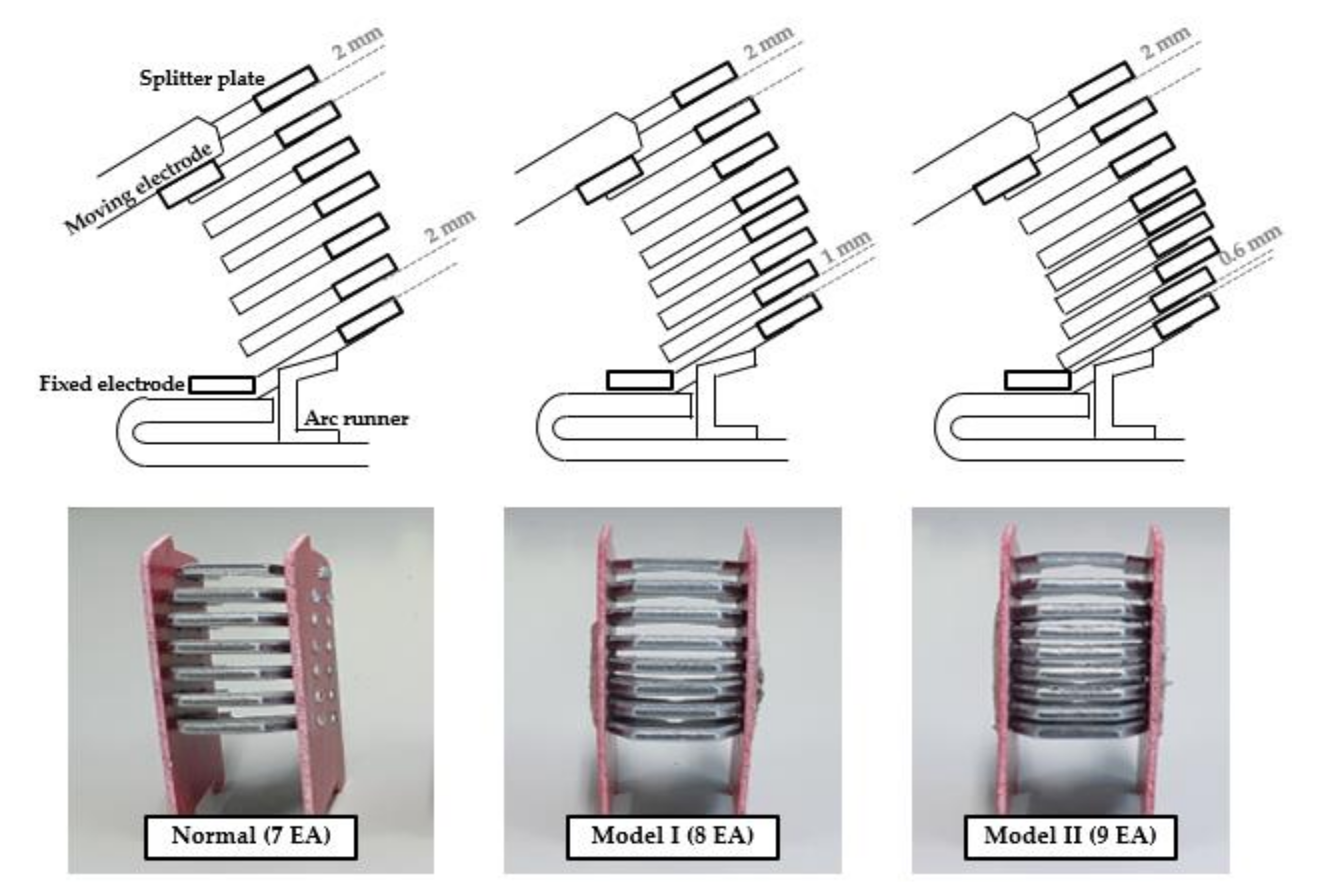
Next, a structural study of the splitter plate was conducted. The fixed electrode was fixed to the lower part, and the moving electrode was opened upward, and the outlet was located on the upper part of the arc-extinguishment section through the splitter plate. In order to increase cooling and adsorption of residual hot gas initially generated, a model for adjusting the lower plate spacing was proposed by adding the plate to the lower part. The structure of the upper part was not changed for the smooth emission of hot gas. The proposed model appears as shown in
Figure 7.
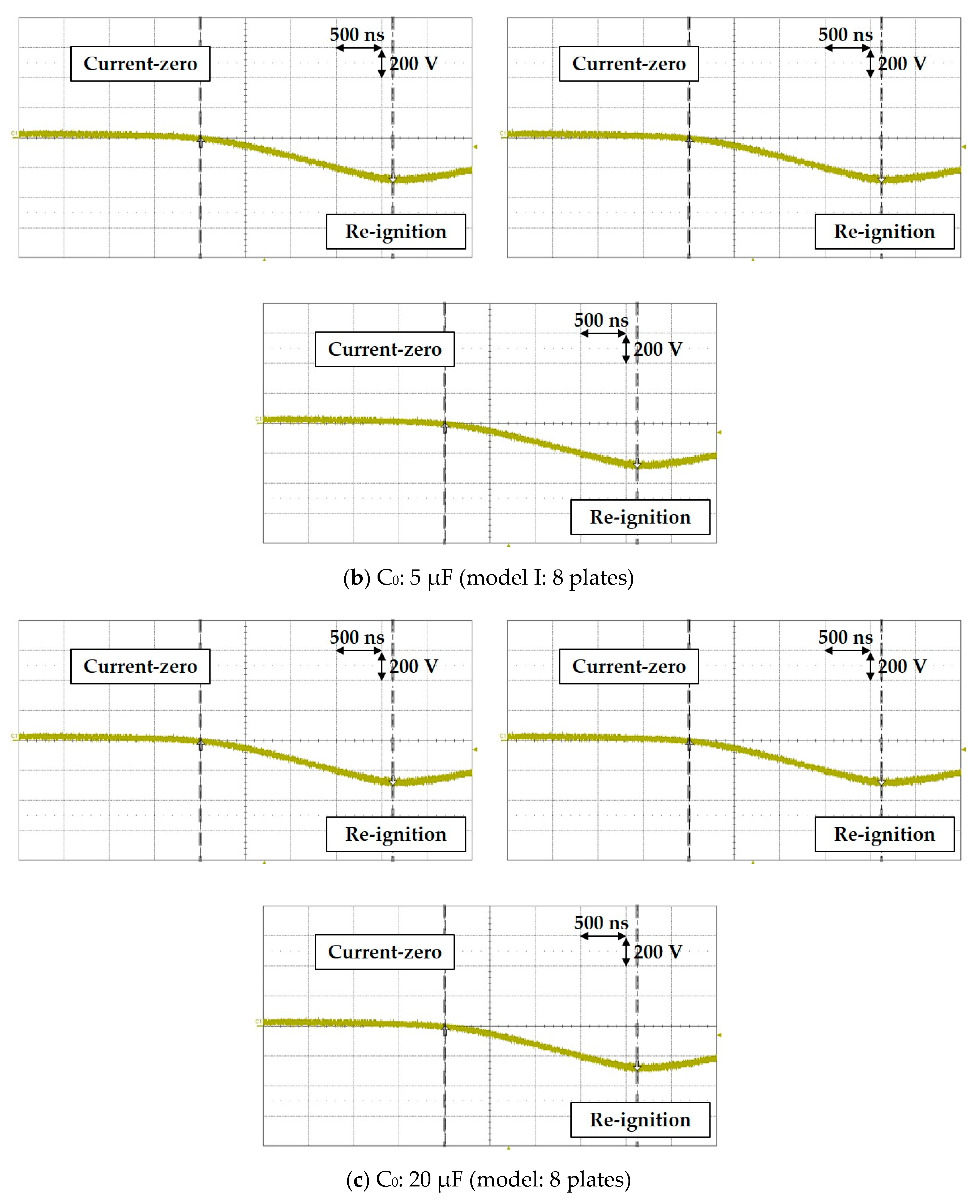
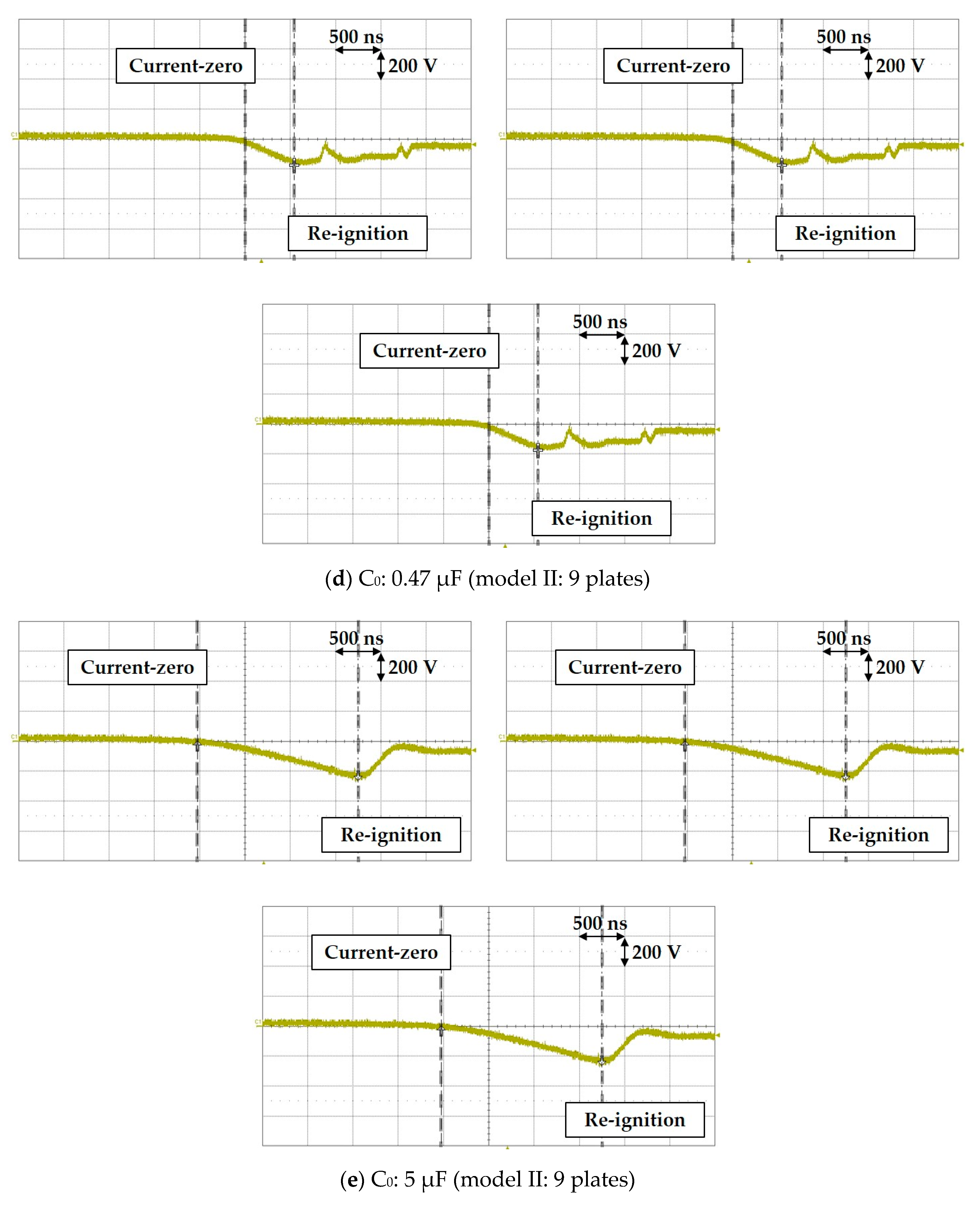
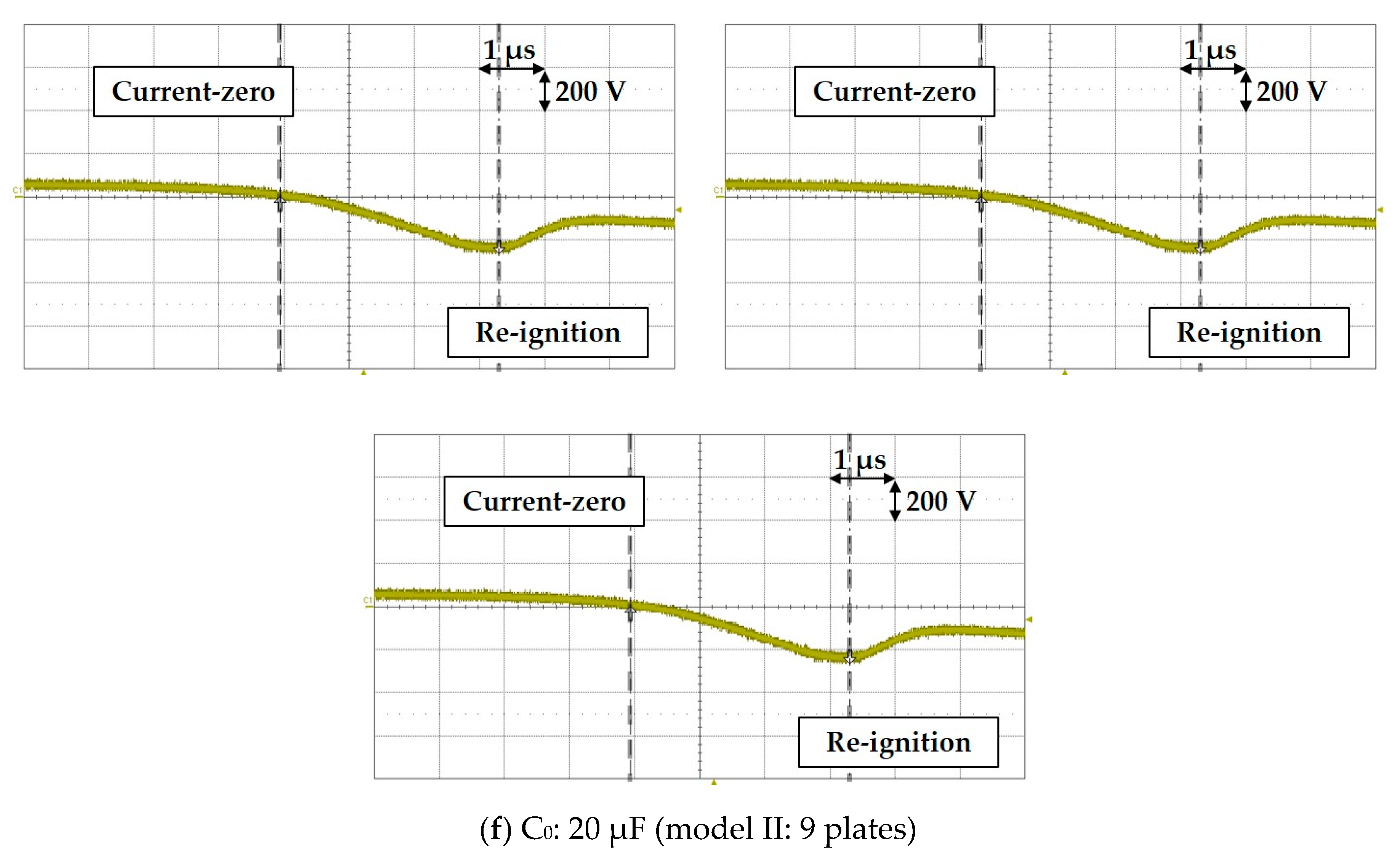
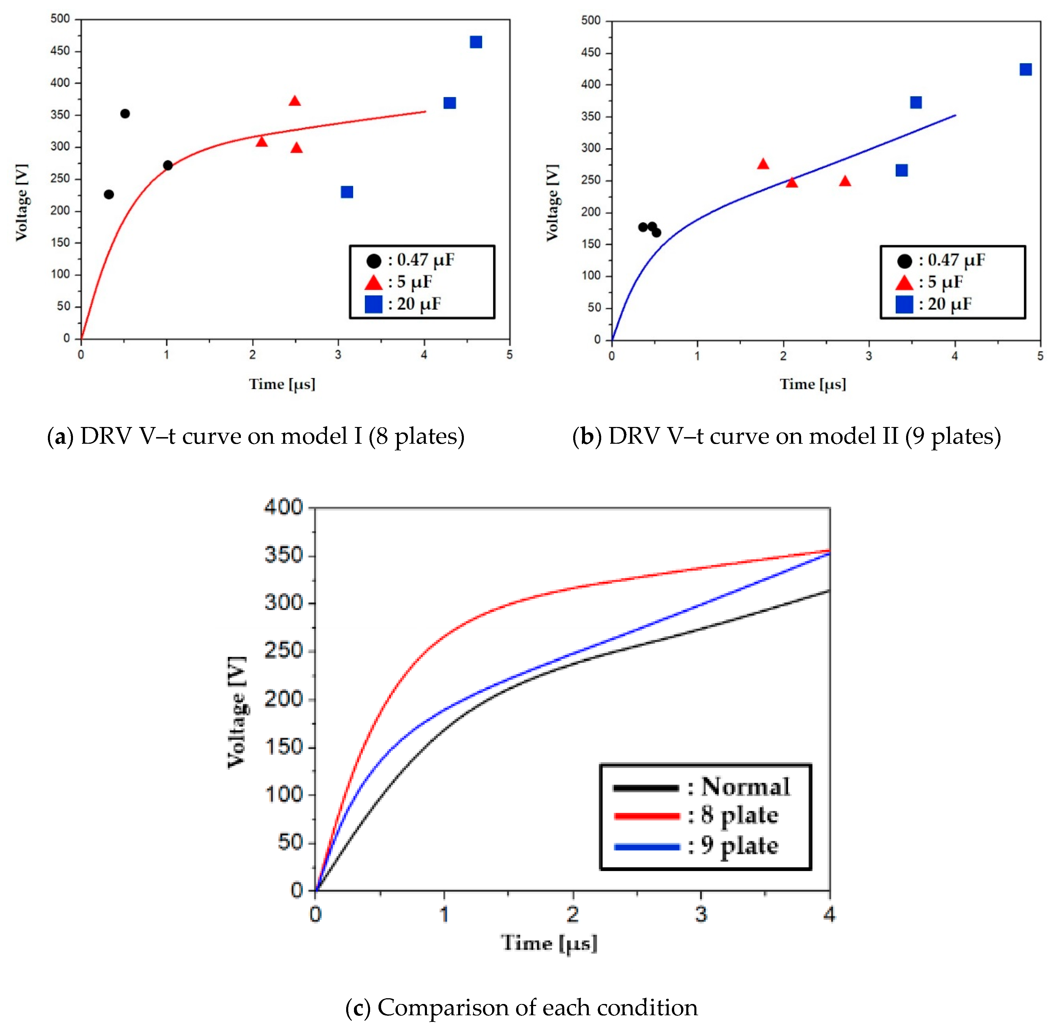
The experimental waveforms of the two proposed models with changed structures are shown in
Figure 8, and the DRV V–t curve is shown in
Figure 9. The results of the experimental measurements are shown in
Table 3.
The DRV curve was derived by using the re-ignition point.
Figure 8a,b,e indicates that the re-ignition point was not clear and was stretched. This occurs when the arc is not sufficiently exhausted, and the recovery period is shortened. In this case, the inflection point of the measured voltage was used. As shown in reference [
15], this phenomenon can be seen in the experimental waveform about the dielectric strength of typical electrodes, and the point of the re-ignition is determined by the marks shown in
Figure 8.
In the two proposed models, it is found that the cooling performance of the initial residual hot gas is improved. Since the structure of the upper plate with outlet was not changed, this shows that it has a similar dielectric strength in the latter period. The initial dielectric strength of model 1 (which consists of eight plates by reducing spacing between the splitter plates to 1 mm) is better than that of model 2 (which consists of nine plates by reducing spacing between the splitter plates to 0.6 mm). Through increasing the number of plates, the two proposed models have better cooling and adsorbing more residual hot gas than the normal model. However, for model 2, the spacing between the plates is so small that there is not enough room for the emission of hot gas.
Table 4 is a summary of the DRV experimental values. These are classified as the initial period affected by the initial cooling of residual hot gas, and the latter period affected by exhaust of residual hot gas (
Figure 3). The initial period is the time when the dielectric recovery voltage V–t curve changes rapidly, and the values vary. Considering the case of the shortest initial period (9-plates), criterion point of the initial period is set at 0.5 μs. The latter period is the time when enough time has passed. Criterion point of the latter period is set to 4 μs. The voltage values over each time are compared with the normal model.
The value of the initial period increases rapidly, but the value of the latter period increases slightly. This is because the material and structure of the splitter plate affects the initial period. In the initial period, copper plates rise the most by 102.1%, and aluminum plates rise by 59.8%. The ratio of these values is similar to the ratio between the values of the thermal conductance (copper (320), aluminum (196), and iron (62)). However, 9-plates, on the other hand, rise by 36.1 percent—the lowest. During the latter period, aluminum plates rise the most by 16.4% and 9-plates rose the least by 8.7%.
3.3. Results Discussion
The experimental results of changing the material and structure of the splitter plate are summarized in
Table 4. To analyze the effect of the experimental results on the initial cooling effect and the later exhaust effect, the result values at 0.5 μs and 4 μs are compared, respectively. Comparing the initial and later period, it is found that the initial improvement is relatively higher than the later. This is because the conditions considered in this paper focus on the cooling effect. Additionally, the later improvement range is from 8.7% to 16.4%, but due to the nature of the repetitive experiments, it is judged to be within the margin of error and the effect is insufficient. The initial cooling effect is the highest with 102.1% improvement over the Cu-based plate, and 36.1% improvement is confirmed under the 9-plate condition. The improvement of the plate in the Al material is found to be 59.8%, which is interesting as the improvement width of the normal plate made of steel and Al and Cu plate is proportional to the value of the thermal conductivity of each material. Therefore, considering the material of the plate, it is possible to improve the dielectric recovery strength early after current-zero by reflecting the thermal conductivity.


