Article

Instability in In0.7Ga0.3As Quantum-Well MOSFETs with Single-Layer Al2O3 and Bi-Layer Al2O3/HfO2 Gate Stacks Caused by Charge Trapping under Positive Bias Temperature (PBT) Stress

1
Department of Semiconductor Processing Equipment, Semiconductor Convergence Campus, Korea Polytechnics, Anseong-si 17550, Korea
2
Department of Electronics Engineering, Kyungpook National University, Daegu 41566, Korea
3
School of Electrical Engineering, University of Ulsan, 93, Daehak-ro, Nam-gu, Ulsan 44610, Korea
*
Authors to whom correspondence should be addressed.
Electronics 2020, 9(12), 2039; https://doi.org/10.3390/electronics9122039
Submission received: 5 November 2020 / Revised: 25 November 2020 / Accepted: 25 November 2020 / Published: 1 December 2020
(This article belongs to the Section Semiconductor Devices)

Abstract

:
The instability of transistor characteristics caused by charge trapping under positive bias temperature (PBT) stress in In0.7Ga0.3As metal oxide semiconductor field-effect transistors (MOSFETs) with single-layer Al2O3 and bi-layer Al2O3/HfO2 gate stacks was investigated. The equivalent field across the multi-gate stacks was compared with a single layer used to compare the instability of electrical characteristics. The observed threshold voltage degradation (ΔVT) was consistent with the phenomenon of fast transient trapping of injected electrons at pre-existing shallow defects in the high-κ dielectric of HfO2, in which this charging was recovered by applying a relaxation voltage. Excluding the fast-transient charging components, the power law exponent (n), with respect to the time-dependent threshold voltage degradation, ranged from 0.3 to 0.35 for both single-layer Al2O3 and bi-layer Al2O3/HfO2 gate stacks. This long-term (slow) VT shift, which was strongly correlated with transconductance (Gm) degradation, was attributed to significant charge trapping in the border trap or/and defect sites within the high-κ dielectric.

1. Introduction

III-V n-channel metal oxide semiconductor field-effect transistors (MOSFETs) have demonstrated much better electron mobility and injection velocity than transistors with a silicon (Si) channel, making them attractive for future high-speed, low-power logic applications [1,2,3]. Among the various channel materials (GaAs, InP, GaN, and InGaAs) in III-V MOSFETs [1,2,3,4,5], interest in indium-rich InxGa1-xAs channel materials, x > 0.53, have recently been considered the most promising replacement of conventional Si-based n-channel materials because of their high electron mobility, high drive current capability, and mature technology for defense applications [3,4,5]. The small electron effective mass of indium-rich InxGa1−xAs quantum-well (QW) channels has led to a significant increase of importance of a ballistic transport in the overall electron transport because of the carrier confinement to a deep quantum well [4,5]. The QW structures compared with the n-MOSFET provide better electrostatic control of the channel from the top gate as the devices are aggressively scaled down [4,5]. However, the unstable native oxides on III-V channel materials, such as As2O3, As2O5, and InOx, lead to poor electrical properties [6,7]. To fully benefit from intrinsic properties, it is important to minimize the interfacial defect sites in the interfacial self-cleaning reaction process via atomic layer deposition (ALD) using trimethylaluminum (TMA) as the precursor for the Al2O3 layer [6,7,8]. An Al2O3 layer is insufficient for providing a low equivalent oxide thickness (EOT) and low gate leakage current [4,5]. Therefore, several researchers have deposited high-κ dielectrics, such as HfO2 (~25) and ZrO2 (~30), on ultrathin Al2O3 layers, improving the electrical properties [4,5,9,10]. The defect sites associated with interfacial traps and high-κ dielectric layers deteriorate the subthreshold-swing (SS) and mobility in the channel, and therefore degrade the on current (ION)/off current (IOFF) ratio [4]. Electron trapping phenomena for InGaAs QW MOSFETs with a high-κ dielectric during device operation can cause a frequency dispersion and shift in ΔVT, which would cause a severe reliability concern [9,10]. Use of the InGaAs QW MOSFETs to realize the next n-MOSFET application has faced major reliability issues [9,10]. In particular, the electrical parameters under the positive bias temperature (PBT) stress condition may change over operation time, including the on current, threshold voltage degradation, SS, and transconductance (Gm) degradation [9,10]. The degradation of InGaAs QW MOSFETs under the PBT stress condition might be more important than that of the Si-based MOSFETs due to higher interfacial trap density (Dit) and border and bulk traps with high-κ dielectric. There have been only a few reports regarding the relevant instability of electrical characteristics issues in In0.7Ga0.3As QW MOSFETs with high-κ dielectrics.
In this paper, we report a study on the instability of electrical characteristics for In0.7Ga0.3As QW MOSFETs with single-layer Al2O3 and bi-layer Al2O3/HfO2. To verify the degradation mechanism of In0.7Ga0.3As QW MOSFETs with the high-κ dielectric under PBT stress condition, the electrical field across single-layer Al2O3 and bi-layer Al2O3/HfO2 gate stacks were observed. Finally, we investigated the relationship between ΔVT degradation, injected charge, and Gm.Max degradation under different PBT stress conditions in In0.7Ga0.3As QW MOSFETs with single-layer Al2O3 and bi-layer Al2O3/HfO2 gate stacks.

2. Experimental Details

The epitaxial layer in the In0.7Ga0.3As QW MOSFETs consists of a heavily doped n+ InGaAs capping layer, an In0.7Ga0.3As channel, an inverted Si δ-doping layer, and an In0.48Al0.52As back buffer or barrier on an InP substrate [3,4,5]. Mesa etching was performed by wet chemical etching to isolate the devices. Source and drain ohmic contacts to the n+ InGaAs were formed using e-beam evaporation and subsequent lift-off of the Mo/Ti/Au metal stack. SiO2 was deposited at the temperatures <150 °C by plasma-enhanced chemical vapor deposition (PECVD), and the gate pattern was defined by electron beam lithography (EBL). SiO2 on the heavily doped n+ InGaAs capping layer was etched using CF4 reactive ion etching (RIE). Gate recess process of the heavily doped n+ InGaAs capping layer was etched to expose the InP layer using an H3PO4 based solution. Then, either Al2O3 (2.0 nm) or Al2O3 (0.7 nm)/HfO2 (1.6 nm) stacked dielectrics were grown sequentially on the In0.7Ga0.3As channel using ALD. Deposition temperatures used for the Al2O3 and HfO2 were 250 °C and 150 °C, respectively. After deposition of the high-κ gate stack on the In0.7Ga0.3As channel, a 5-nm TiN metal-gate (MG) was deposited in-situ by ALD. Finally, a Ti/Au gate metal pad was deposited by beam evaporation. The electrical characteristics were evaluated using an Agilent 4156C semiconductor parameter analyzer. The PBT stress condition (VGS − VT = Vstress), which was normalized to VT, was applied at the gate with the other terminals grounded. The instability of electrical characteristics under PBT stress condition was performed by a Summit 11K Cascade probe station with an integrated Temptronic thermochuck able to heat the wafer till temperatures to 200 °C. The injected electron on each stress time was being monitored by the gate current under the PBT stress condition. The injected charge (Qinj) was obtained from the monitored gate current integral of each stress time.

3. Results and Discussion

3.1. Distribution of the Electrical Field Across Gate Stacks on the Applied Stress Voltage

To compare the instability of electrical characteristics of single layer and multi-gate stacks, it is imperative to consider the equivalent field across the multi-gate stacks compared with a single layer because it is further complicated by the interaction between different materials [11,12]. The In0.7Ga0.3As QW MOSFETs structure with a high-κ dielectric usually consists of multi-gate stacks, including the interfacial layer and the high-κ dielectric layer. Hence, the electrical field across multi-gate stacks can be determined easily base on simple electrostatics rules as reported in References [11,12]. The electrical field in bi-layer Al2O3/HfO2 gate stacks in the In0.7Ga0.3As QW MOSFETs is given by Equation (1) [11]
E A l 2 O 3 = V A ( ε A l 2 O 3 ε H f O 2 ) t H f O 2 + t A l 2 O 3 E H f O 2 = V A ( ε H f O 2 ε A l 2 O 3 ) t A l 2 O 3 + t H f O 2
where EHfO2 and EAl2o3 are the electrical fields across the high-κ dielectric and interfacial layers, respectively. tHfO2 and tAl2O3 are the physical thicknesses. κHfO2 and κAl2O3 are the dielectric constants. VA is the applied voltage or the applied stress voltage across gate stack.
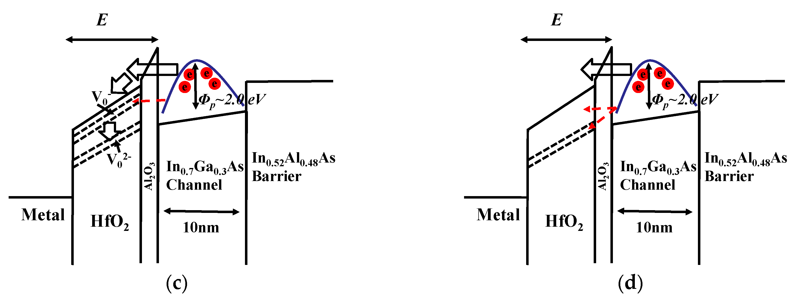
To understand the role of the interfacial layer and high-κ dielectric layer, the calculated electrical field and the energy-band diagram for single-layer Al2O3 and bi-layer Al2O3/HfO2 is plotted with respect to the applied stress voltage as shown in Figure 1. If the electrical field in the ultra-thin interfacial layer is sufficiently high, most carriers of InGaAs channel easily tunnel across the interfacial layer to border traps or/and defect sites within the high-κ dielectric layers [11,13,14]. It is important to verify the degradation of the main high-κ dielectric layer caused by the applied stress voltage.
The electric field in the main high-κ layers, which are HfO2 for bi-layer Al2O3/HfO2 gate stacks and Al2O3 for single-layer Al2O3, is similar according to the calculated effective thickness. Generally, the electrical stress fields in the silicon dioxide layer in Si-based high-κ dielectric and silicon germanium (SiGe) MOSFETs have been reported to be on the order of 5–6 MV/cm, which is a dominant region in the Fowler–Nordheim (F-N) tunneling mechanism [11,12]. Although the time zero dielectric breakdown (TZDB) voltage of the high-κ dielectrics in III-V MOSFETs is similar to the values previously reported for high-κ dielectrics [11,12], the smaller band gap of the InGaAs channel and higher Dit between the InGaAs channel and interfacial layer in III-V MOSFETs may seriously degrade the dielectric/substrate interface and high-κ region because of the high vertical field [11,12]. Because these phenomena are related to the properties (effective mass, band gap, etc.) of the channel materials themselves, these stress conditions for the QW III-V MOSFETs, which are 5–6 M/cm, may be inadequate. Therefore, the appropriate PBT stress voltage should be chosen considering the properties of the channel materials and the higher Dit between the InGaAs channel and high-κ dielectric.

3.2. Impact of Charge Trapping in Defect Sites under Positive Bias Temperature (PBT) Stress Condition

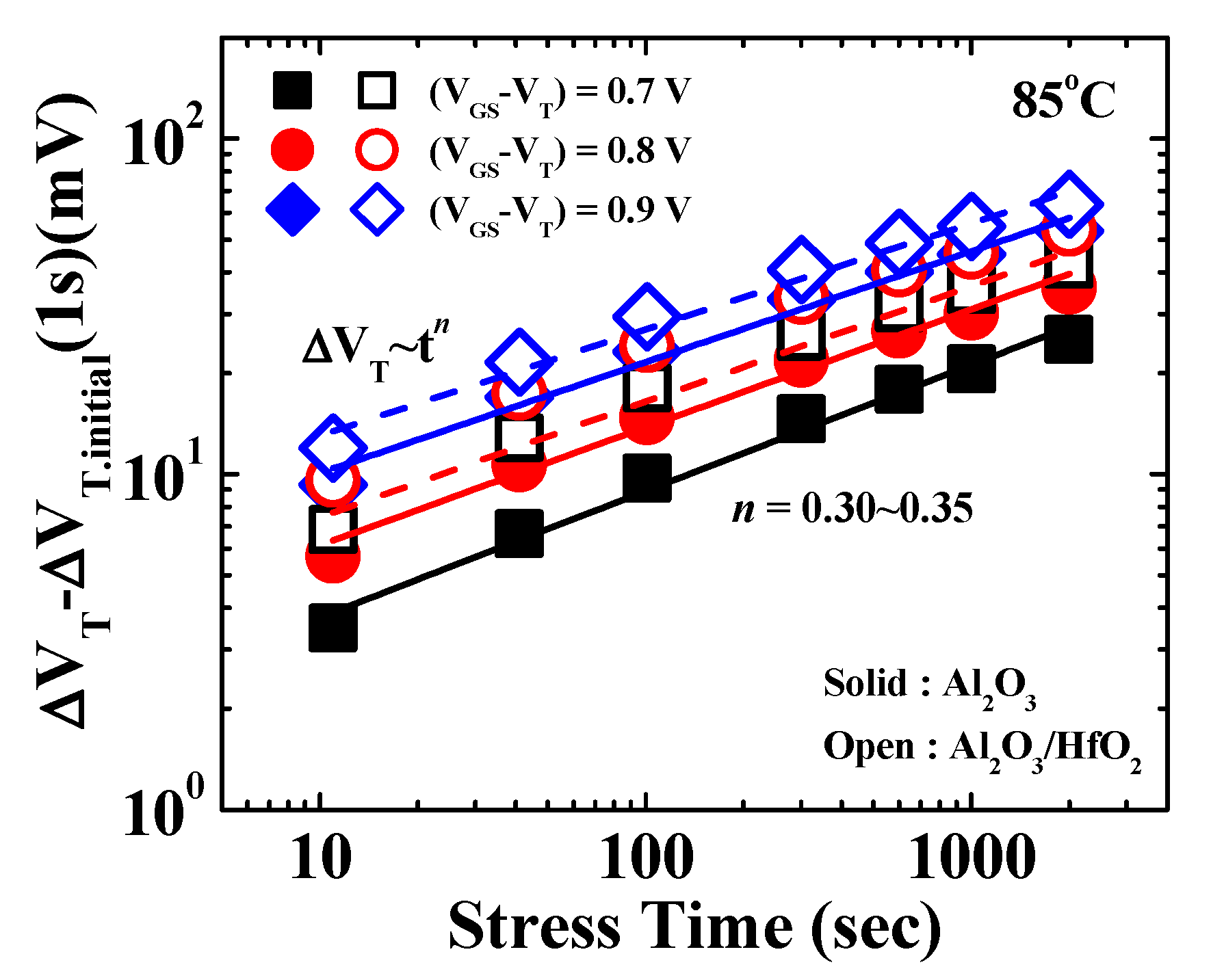
Figure 2 presents the trapping and relaxation characteristics during two stress/recovery cycles for single-layer Al2O3 and bi-layer Al2O3/HfO2 In0.7Ga0.3As QW MOSFETs under different PBT stress conditions. The observed threshold voltage degradation (ΔVT) is consistent with the phenomenon of electron trapping at defect sites within the high-κ dielectric layer. These charges can be detrapped by applying a relaxation voltage at VGS = 0 V, as shown in Figure 2. The ΔVT degradation may be related to two types of traps: The fast-transient trap over short durations (<1 msec) and the slow trap over long durations [13,14,15,16,17,18]. The initial VT shift for single-layer Al2O3 and bi-layer Al2O3/HfO2 In0.7Ga0.3As QW MOSFETs during the first 1 s of DC stress shows a substantial change because of the fast transient charging at defect sites in the HfO2 dielectric, while the initial ΔVT shift is much less in the Al2O3 In0.7Ga0.3As QW MOSFETs [15,16,17,18]. The fast-transient charging is from electron tunneling from the InGaAs surface directly into the pre-existing shallow traps within the high-κ dielectric layer, which should be subtracted from the initial 1 s stress for a more accurate evaluation [13,14]. The time dependence of the ΔVT degradation was investigated to quantitatively studying the charge trapping phenomenon. After subtracting the fast-transient charge trapping component, which is reported to fully saturate within <1 s of stress, the time dependency of the VT shift (ΔVT − ΔVT.initial (1 s)) can be described by a power law expression ΔVT~tn [13,14,15,16,17,18,19]. The exponent n of this dependency is in the range of 0.3 to 0.35 for single-layer Al2O3 and bi-layer Al2O3/HfO2 gate stacks, as shown in Figure 3. Note that ΔVT values for bi-layer Al2O3/HfO2 gate stacks are greater than that for single-layer Al2O3 while the exponent n values are similar, which are likely associated with the higher trap density in the HfO2.
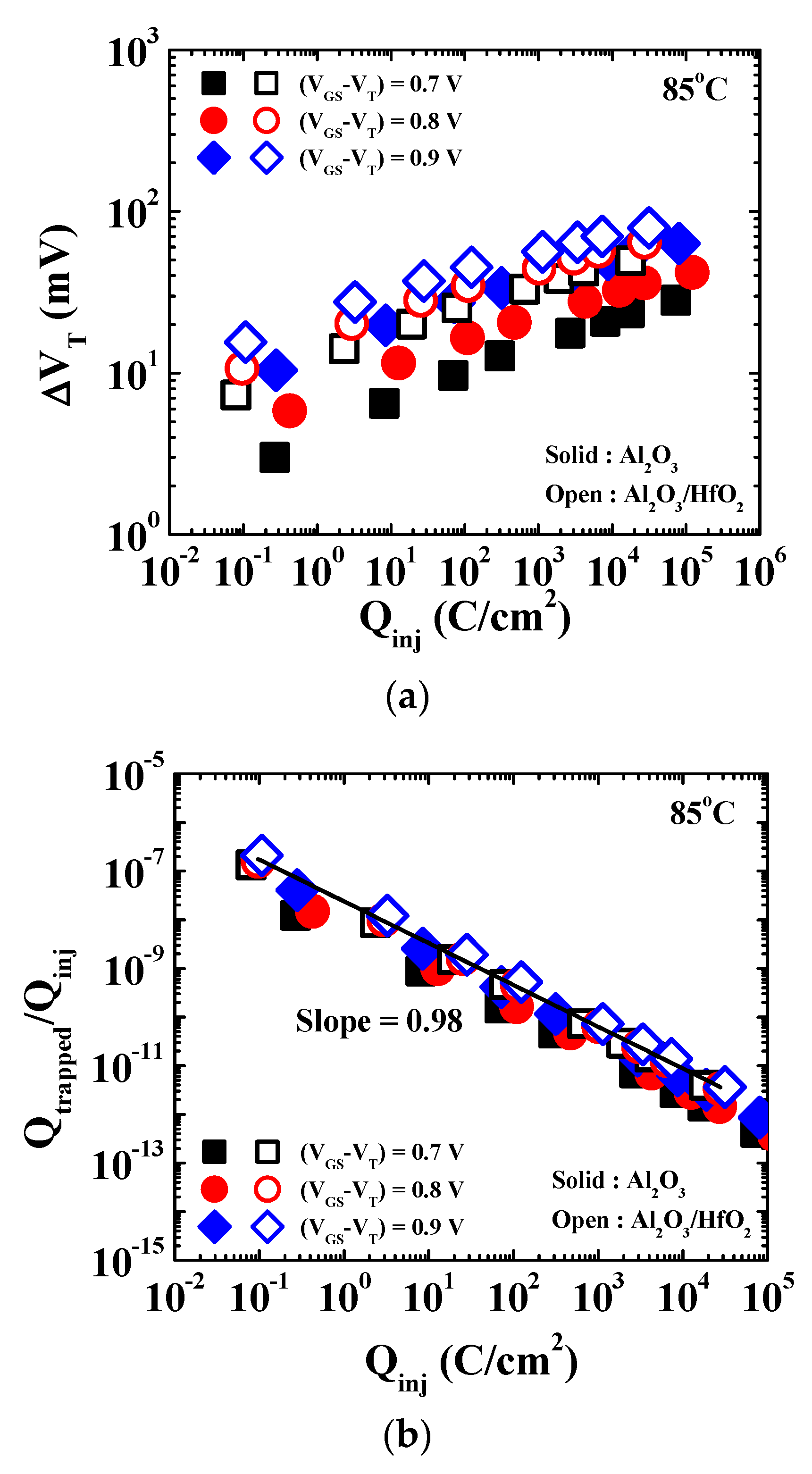
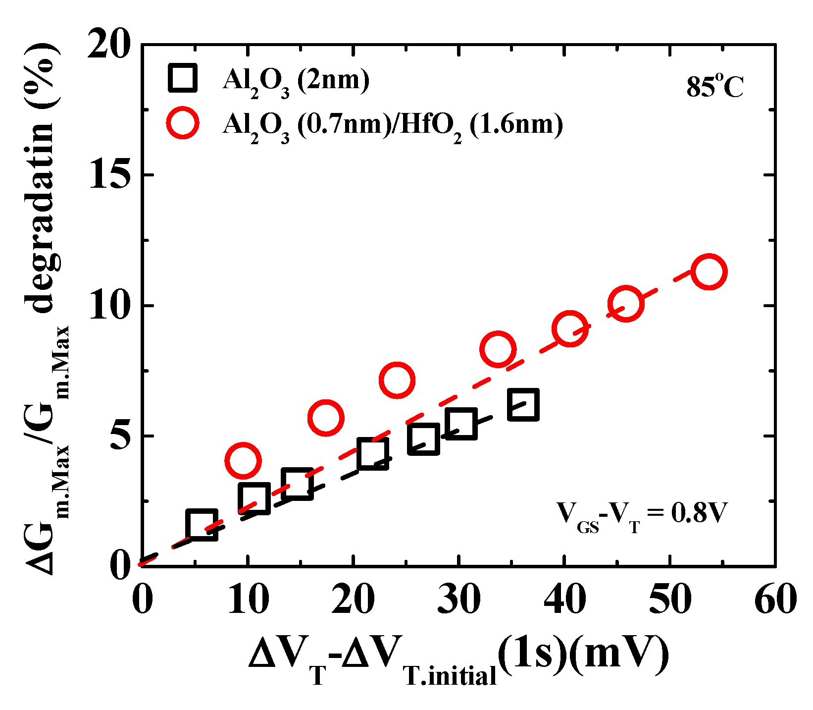
To further investigate the charge trapping characteristics, ΔVT was plotted as a function of the injected charge under different PBT stress conditions as shown in Figure 4a. The similar slopes of Qtrapped/Qinj for single-layer Al2O3 and bi-layer Al2O3/HfO2 gate stacks (Figure 4b) indicate that these stacks exhibited similar charge trapping efficiencies [11,15,16,20,21,22]. The injected charges from the InGaAs channel are mostly trapped in defect sites within the high-κ dielectric. The long-term VT shift, ΔVT – ΔVT.initial (1 s), correlates well with the percentage of transconductance (%Gm.Max) degradation for single-layer Al2O3 and bi-layer Al2O3/HfO2 gate stacks, as shown in Figure 5. Generally, Gm.Max degradation is related to the generation of interfacial state traps and Coulomb centers in the near-interface dielectric region [21,22]. However, Gm.Max degradation increases as the amount of trapped electrons increases, as shown in Figure 5, which means that remote scattering is a sensitive factor in high-κ dielectric [11,15,16,20,21,22]. Therefore, the correlation seen between the Gm.Max and ΔVT − ΔVT.initial (1 s) implies that significant charge trapping occurred in the border trap or/and defect sites within the high-κ dielectric, which is in the main high-κ dielectric layers for single-layer Al2O3 and bi-layer Al2O3/HfO2 gate stacks.
Although the bi-layer Al2O3/HfO2 gate stack in In0.7Ga0.3As QW MOSFETs demonstrated superior electrical performance (compared with the Al2O3) because of its lower EOT [3,4,5], a large density of oxygen vacancies within high-κ dielectrics still caused VT instability [11,15,16,17,18,20,21,22,23]. Since the defects in the HfO2-based dielectrics are related to oxygen vacancies in different charge states, from V2+ to V2− levels as shown in Figure 1c [11,17,21,22,23], which can reversibly trap the injected electrons, improving the reliability characteristics of high-κ dielectric devices requires oxygen vacancies to be passivated. One of the methods is a high-pressure hydrogen or deuterium annealing.

4. Conclusions

We investigated the instability of electrical characteristics of III-V MOSFETs with single-layer Al2O3 and bi-layer Al2O3/HfO2 gate stacks under PBT stress. The initial (within the first stress second) ΔVT shift in the bi-layer Al2O3/HfO2 III-V MOSFETs was consistent with the phenomenon of fast transient trapping/detrapping of injected electrons at pre-existing shallow defects in the high-κ dielectric film. Long-term VT degradation with single-layer Al2O3 and bi-layer Al2O3/HfO2 gate stacks in III-V QW MOSFETs exhibited slow charging responsible for the ΔVT power law time dependency. The observed correlation between the %Gm.Max and ΔVT − ΔVT.initial (1 s) degradations indicated that this slow charge trapping occurred in border trap or/and defect sites within the high-κ dielectric, which was in the main high-κ dielectric layers of the single-layer Al2O3 and bi-layer Al2O3/HfO2 gate stacks. These results indicate that the defect density must be reduced in the high-κ dielectric to improve the stability of In0.7Ga0.3As QW MOSFETs with single-layer Al2O3 and bi-layer Al2O3/HfO2 gate stacks.

Author Contributions

H.-M.K. conducted most of the experiments and wrote the manuscript including preparing figures and electrical characterization; D.-H.K. supervised the work and reviewed the manuscript; T.-W.K. initiated the work, provided the main idea, and supervised the entire process. All authors analyzed and discussed the results. All authors have read and agreed to the published version of manuscript.

Funding

This work was supported by a National Research Foundation of Korea (NRF) grant funded by the Korean government (MSIP; Ministry of Science, ICT, and Future Planning, NRF-2019R1A2C1009816) and by the Civil-Military Technology Cooperation Program (No. 19-CM-BD-05).

Conflicts of Interest

The authors declare no conflict interest.

References

  1. Del Alamo, J.A. Nanometre-scale electronics with III–V compound semiconductors. Nature 2011, 479, 317–323. [Google Scholar] [CrossRef] [PubMed]
  2. Waldron, N.; Merckling, C.; Teugels, L.; Ong, P.; Ansar, S.; Ibrahim, U.; Sebaai, F.; Pourghaderi, A.; Barla, K.; Collaert, N.; et al. InGaAs Gate-All-Around Nanowire Devices on 300 mm Si Substrates. IEEE Electron Device Lett. 2014, 35, 1097–1099. [Google Scholar] [CrossRef]
  3. Kim, T.-W.; Koh, D.-H.; Shin, C.-S.; Park, W.-K.; Orzali, T.; Hobbs, C.; Maszara, W.P.; Kim, D.-H. Lg = 80 -nm Trigate Quantum-Well In 0.53 Ga 0.47 As Metal–Oxide–Semiconductor Field-Effect Transistors With Al2O3/HfO2 Gate-Stack. IEEE Electron Device Lett. 2015, 36, 223–225. [Google Scholar] [CrossRef]
  4. Kim, D.; Alamo, J.A.; Antoniadis, D.A.; Brar, B. Extraction of Virtual-Source Injection Velocity in sub-100 nm III-V HFETs. In Proceedings of the 2009 IEEE International Electron Devices Meeting (IEDM), Baltimore, MD, USA, 7–9 December 2009; Volume 3, pp. 861–864. [Google Scholar]
  5. Kim, T.-W.; Kim, D.-H.; Koh, D.-H.; Hill, R.J.W.; Lee, R.T.P.; Wong, M.H.; Cunningham, T.; del Alamo, J.A.; Banerjee, S.K.; Oktyabrsky, S.; et al. ETB-QW InAs MOSFET with scaled body for improved electrostatics. In Proceedings of the 2012 International Electron Devices Meeting, San Francisco, CA, USA, 10–13 December 2012; pp. 32.3.1–32.3.4. [Google Scholar]
  6. Taoka, N.; Yokoyama, M.; Kim, S.H.; Suzuki, R.; Iida, R.; Lee, S.; Hoshii, T.; Jevasuwan, W.; Maeda, T.; Yasuda, T.; et al. Impact of Fermi Level Pinning inside Conduction Band on Electron Mobility of In x Ga 1-x As MOSFETs and Mobility Enhancement by Pinning Modulation. In Proceedings of the International Electron Devices Meeting, Washington, DC, USA, 5–7 December 2011; pp. 27.2.1–27.2.4. [Google Scholar]
  7. Engel-Herbert, R.; Hwang, Y.; Stemmer, S. Comparison of methods to quantify interface trap densities at dielectric/III-V semiconductor interfaces. J. Appl. Phys. 2010, 108, 124101. [Google Scholar] [CrossRef] [Green Version]
  8. Yum, J.H.; Akyol, T.; Ferrer, D.A.; Lee, J.C.; Banerjee, S.K.; Lei, M.; Downer, M.; Hudnall, T.W.; Bielawski, C.W.; Bersuker, G. Comparison of the self-cleaning effects and electrical characteristics of BeO and Al2O3 deposited as an interface passivation layer on GaAs MOS devices. J. Vac. Sci. Technol. A Vac. Surf. Films 2013, 29, 061501. [Google Scholar] [CrossRef]
  9. Yuan, Y.; Wang, L.; Yu, B.; Shin, B.; Ahn, J.; McIntyre, P.C.; Asbeck, P.M.; Rodwell, M.J.W.; Taur, Y. A Distributed Model for Border Traps in Al2O3—InGaAs MOS Devices. IEEE Electron Device Lett. 2011, 32, 485–487. [Google Scholar] [CrossRef]
  10. Goel, N.; Heh, D.; Koveshnikov, S.; Ok, I.; Oktyabrsky, S.; Tokranov, V.; Kambhampatic, R.; Yakimov, M.; Sun, Y.; Pianetta, P.; et al. Addressing The Gate Stack Challenge For High Mobility InxGa1-xAs Channels For NFETs. In Proceedings of the 2008 IEEE International Electron Devices Meeting, San Francisco, CA, USA, 15–17 December 2008; pp. 1–4. [Google Scholar]
  11. Bersuker, G.; Park, C.S.; Barnett, J.; Lysaght, P.S.; Kirsch, P.D.; Young, C.D.; Choi, R.; Forank, B.H.L.; Benthem, V.; Lenahan, S.J.P.M.; et al. The effect of interfacial layer properties on the performance of Hf-based gate stack devices the effect of interfacial layer properties on the performance of Hf-based gate stack devices. J. Appl. Phys. 2006, 100, 094108. [Google Scholar] [CrossRef]
  12. Chowdhury, N.A.; Bersuker, G. Breakdown characteristics of nFETs in inversion with metal/HfO2 gate stacks. Microelectron. Eng. 2008, 85, 27–35. [Google Scholar] [CrossRef]
  13. Heh, D.; Young, C.D.; Choi, R.; Bersuker, G. Extraction of the Threshold-Voltage Shift by the Single-Pulse Technique. IEEE Electron Device Lett. 2007, 28, 734–736. [Google Scholar] [CrossRef]
  14. Heh, D.; Young, C.D.; Brown, G.A.; Hung, P.Y.; Diebold, A.; Bersuker, G.; Vogel, E.M.; Bernstein, J.B.; Vogel, E.M.; Bernstein, J.B. Spatial distributions of trapping centers in HfO2/SiO2 gate stacks. Appl. Phys. Lett. 2011, 88, 152907. [Google Scholar] [CrossRef] [Green Version]
  15. Young, C.D.; Zeitzoff, P.; Brown, G.A.; Member, L.S.; Bersuker, G.; Lee, B.H.; Hauser, J.R.; Fellow, S.; Hauser, J.R. Intrinsic mobility evaluation of high-/spl kappa/gate dielectric transistors using pulsed Id-Vg. IEEE Electron Device Lett. 2005, 26, 586–589. [Google Scholar] [CrossRef]
  16. Young, C.D.; Heh, D.; Neugroschel, A.; Choi, R. Electrical characterization and analysis techniques for the high-κ era. Microelectron. Reliab. 2007, 47, 479–488. [Google Scholar] [CrossRef]
  17. Choi, E.A.; Chang, K.J. Charge-transition levels of oxygen vacancy as the origin of device instability in HfO2 gate stacks through quasiparticle energy calculations. Appl. Phys. Lett. 2009, 94, 122901. [Google Scholar] [CrossRef]
  18. Wu, W.C.; Lai, C.-S.; Wang, T.-M.; Wang, J.-C.; Hsu, C.W.; Ma, M.W.; Lo, W.-C.; Chao, T.S. Carrier Transportation Mechanism of the TaN/HfO2/IL/Si Structure with Silicon Surface Fluorin Implantation. IEEE Trans. Electron Devices 2008, 55, 1639–1646. [Google Scholar] [CrossRef]
  19. Cho, M.; Lee, J.; Aoulaiche, M.; Kaczer, B.; Roussel, P.; Kauerauf, T.; Degraeve, R.; Franco, J.; Ragnarsson, L.-åke; Groeseneken, G. Insight Into N/PBTI Mechanisms in Sub-1-nm-EOT Devices. IEEE Trans. Electron Devices 2012, 59, 2042–2048. [Google Scholar] [CrossRef]
  20. Kreber, A.; Cartier, E.; Pantisano, L.; Rosmeulen, M.; Degraeve, R.; Kauerauf, T.; Groeseneken, G.; Maes, H.E.; Schwalke, U. Characterization Of The Vt-Instability In Sio2/Hfo2 Gate Dielectrics. Proc. IEEE Int. Reliab. Phys. Symp. 2003, 41–45. [Google Scholar] [CrossRef]
  21. Park, H.; Rahman, M.S.; Chang, M.; Lee, B.H.; Choi, R.; Young, C.D. Improved Interface Quality and Charge-Trapping Characteristics of MOSFETs with High- Gate Dielectric. IEEE Electron Device Lett. 2005, 26, 725–727. [Google Scholar] [CrossRef]
  22. Bersuker, G.; Sim, J.H.; Park, C.S.; Young, C.D.; Nadkarni, S.V.; Choi, R.; Lee, B.H. Mechanism of Electron Trapping and Characteristics of Traps in HfO2 Gate Stacks. IEEE Trans. Device Mater. Reliab. 2007, 7, 138–145. [Google Scholar] [CrossRef]
  23. Afanas’ev, V.; Stesmans, A.; Chen, F.; Shi, X.; Campbell, S.A. Internal photoemission of electrons and holes from (100) Si into HfO2. Appl. Phys. Lett 2002, 81, 1053–1055. [Google Scholar] [CrossRef]
Figure 1. Distribution of each electrical field across (a) single-layer Al2O3 and (b) bi-layer Al2O3/HfO2 on the applied stress voltage. Schematics of energy band diagram of (c) single-layer Al2O3 and (d) bi-layer Al2O3/HfO2 under positive bias temperature (PBT) stress conditions.
Electronics 09 02039 g001aElectronics 09 02039 g001b
Figure 2. Comparison of charge trapping and relaxation characteristics in In0.7Ga0.3As metal oxide semiconductor field-effect transistor (MOSFET) with (a) single-layer Al2O3 and (b) bi-layer Al2O3/HfO2 gate stacks under PBT stress at different overdrive conditions.
Electronics 09 02039 g002
Figure 3. The power law time dependency of the observed threshold voltage degradation (ΔVT) excluding the fast-transient charge trapping components (ΔVT – ΔVT.initial (1 s)) in single-layer Al2O3 and bi-layer Al2O3/HfO2 gate stacks under PBT stress conditions. The power law exponent n is 0.30–0.35.
Electronics 09 02039 g003
Figure 4. (a) ΔVT degradation as a function of the injected charge for an In0.7Ga0.3As quantum-well (QW) MOSFETs with single-layer Al2O3 and bi-layer Al2O3/HfO2 gate stacks under PBT stress conditions and (b) the Qtrapped/Qinj ratio as a function of the injected charge for both gate stacks.
Electronics 09 02039 g004
Figure 5. ΔVT−ΔVT.initial (1 s) shift versus %Gm.Max degradation in In0.7Ga0.3As MOSFETs with single-layer Al2O3 and bi-layer Al2O3/HfO2 gate stacks. Correlation between ΔVT − ΔVT.initial (1 s) and %Gm.Max degradation is detectible in single-layer Al2O3 and bi-layer Al2O3/HfO2 gate stacks.
Electronics 09 02039 g005
Publisher’s Note: MDPI stays neutral with regard to jurisdictional claims in published maps and institutional affiliations.