Article

Research of PVDF Energy Harvester Cantilever Parameters for Experimental Model Realization

by
Mindaugas Cepenas
1,
Bingzhong Peng
1,
Darius Andriukaitis
1,*,
Chandana Ravikumar
1,
Vytautas Markevicius
1,
Neringa Dubauskiene
1,
Dangirutis Navikas
1,
Algimantas Valinevicius
1,
Mindaugas Zilys
1,
Audrius Merfeldas
1 and
Nikolay Hinov
2
1
Department of Electronics Engineering, Kaunas University of Technology, Studentu St. 50-438, LT-51368 Kaunas, Lithuania
2
Department of Power Electronics, Faculty Electronic Engineering and Technology, Technical University of Sofia, BG-1000 Sofia, Bulgaria
*
Author to whom correspondence should be addressed.
Electronics 2020, 9(12), 2030; https://doi.org/10.3390/electronics9122030
Submission received: 19 October 2020 / Revised: 20 November 2020 / Accepted: 24 November 2020 / Published: 1 December 2020
(This article belongs to the Special Issue Vehicles Technologies for Sustainable Smart Cities)

Abstract

:
Piezoelectric energy harvesters have been extensively researched for use with wireless sensors or low power consumption electronic devices. Most of the piezoelectric energy harvesters cannot generate enough power for potential applications. In this study, we explore the parameters, including gap and proof mass, that can affect the damping of the cantilever to optimize the design of the energy harvester. A finite analysis is conducted using COMSOL Multiphysics software. Usually, this type of simulation is performed using the loss factor. However, it is known that results from the loss factor produce models that do not fit the experimental data well. In fact, the result of output voltage using the loss factor is 50% higher than the real value, which is due to ignoring the adverse effect of a superimposing mechanical damping of different constituent materials. In order to build a true model, Rayleigh damping coefficients are measured to use in a simulation. This resulted in a closer fit of modeling and experimental data, and a 5 times better output voltage from the optimized energy harvester compared with using the smallest gap and mass.

1. Introduction

Over the past several years, energy harvesting has been an attractive research topic due to the increased awareness of energy conservation. This interest stems from the need to power wireless electronics, microelectromechanical systems, and implanted biomedical devices, and so on [1,2,3]. Most of these low power electronic devices are dependent on batteries, which are difficult or, in some cases, impossible to recharge and replace, as well as being detrimental to the environment. Therefore, many researchers are focused on energy harvesting techniques. The transduction mechanisms used for transforming vibration to electric power include electromagnetic, electrostatic, and piezoelectric mechanisms [4,5]. Electromagnetic induction technology relies on the relative motion of a magnet and the coil or the change of the magnetic field, which makes the application difficult to implement. Electrostatic conversion also has significant disadvantages [6]. Because of the unique advantages such as flexibility, long service life, wide range of frequencies, a strong piezoelectric response, low acoustic impedance, easy to fabricate and implement structure of the cantilevers, and so on, the piezoelectric option has become significantly important. When mechanical force is applied to piezoelectric materials, electrical charges are induced; therefore, piezoelectric materials can be used as electromechanical energy converters.
Cantilever-based piezoelectric energy harvesters are the most common devices for converting vibration to electricity. Although low energy electronic devices consume power from several μW to mW, supplying them with power from vibration with piezoelectric energy harvesters is insufficient. Because the ambient vibrations are of random frequency and these vibration amplitudes are small due to the small acceleration available [7,8,9]. To overcome this problem, many factors which have a significant effect on power production are investigated to optimize cantilever-based piezoelectric energy harvesters. On the one hand, by optimizing the geometry of the cantilever beam, the output power of piezoelectric materials can be increased. The optimization and implementation of the geometry of piezoelectric cantilevers have been reported by several researchers. The shape of piezoelectric materials, for example, a separated piezoelectric patch [10] and arc-shaped energy harvesters [11], is investigated. Three different shapes—near edge width quadratic (NEWD), half quadratic, and trapezoidal—were analyzed, and the results showed NEWD has a better performance in terms of output power [12]. By varying the geometries of the cantilever beam, it was found that a tapered cantilever had a better performance than a rectangle beam [13,14]. For practical cases, where the energy harvester is excited randomly, a clamped circular plate energy harvester interconnected to a circular piezoelectric layer was designed to optimize the performance, because if the resonant frequency of the designed beam is close to the available mechanical vibrations, the displacement of the beam is maximum and hence, it generates maximum power output [15]. Two low frequency piezoelectric cantilever beams were designed after research of the relationship between the dimensions and the natural frequencies [16]. The frequency up conversion technique was adopted to harvest the inertial energy of human walking motion, which has a low frequency [17,18,19]. On the other hand, quite recently, investigations showed that if a piezoelectric energy harvester in the form of a cantilever beam is split into several pieces, or the piezoelectric materials are split into several layers, and then, electrically connected in a parallel way, the output will become higher compared with the output of a single cantilever beam or a single layer material cantilever beam of similar total width and length [20,21]. In the previous investigations, it was reported that there was an increase of 45% in harvested power for single folding, whereas for double folding, the increase could be up to 75% compared with splitting [22]. The reason for the increasing output power is due to the reduction in the damping ratio, which can result in a higher vibration amplitude of the beam. Therefore, the energy harvester can harvest ambient vibrational energy more efficiently. In addition, the piezoelectric energy harvester converts the mechanical vibration energy into AC electrical power. Since most of the electronic devices and rechargeable batteries usually require a DC power supply, a power management circuit is necessary to rectify the AC power to steady DC power [23,24]. Therefore, some researchers focus on the circuit structures for piezoelectric energy harvesters to improve the efficiency of the harvester. The general way to achieve this target is to realize resistive matching [25,26]. These approaches are reasonable as the impedance of a piezoelectric cantilever vibration around the resonant frequency is mostly resistive, which is also considered to be available because they are easy to control and implement.
As was observed above, piezoelectric energy harvesting experiments and simulations are available. Several ways are provided to improve the output power and increase the efficiency of the piezoelectric energy harvester [27,28,29]. However, in the majority of cases, mechanical damping and how it affects the output is not considered and studied. Many researchers simulated the piezoelectric energy harvester model using COMSOL Multiphysics, which explored various parameters, such as excitation frequency, acceleration, thickness of piezoelectric layers, gaps, etc., to improve the output power [30,31,32,33]. In a way, it is possible to improve the simulation results. However, in practice, the mechanical damping of a whole system also changes with respect to the change in other parameters. It is simply inaccurate to superimpose damping of different constituent materials. Therefore, it is extremely important to study and understand the significance of the effects of damping and use damping of a cantilever to optimize the piezoelectric energy harvester.
The aim of this work is to develop a real polyvinylidene fluoride (PVDF) piezoelectric harvester model in COMSOL Multiphysics software and study the effect of mechanical damping. In order to meet the requests of practical applications of the piezoelectric energy harvester as the power source, the damping effects of different gaps and proof masses are explored and the piezoelectric energy harvester is optimized.

2. Modelling of the Piezoelectric Energy Harvester Cantilever

2.1. Device Configuration and Model

A self-powered piezoelectric vibration energy harvesting system is usually composed of four parts: the source of vibration, a piezoelectric energy converter, an electrical interface circuit that converts the generated AC current into the DC current, and an energy storage device that accumulates and stores the energy for intermittent use [34]. The equivalent electromechanical scheme of the setup is shown in Figure 1.
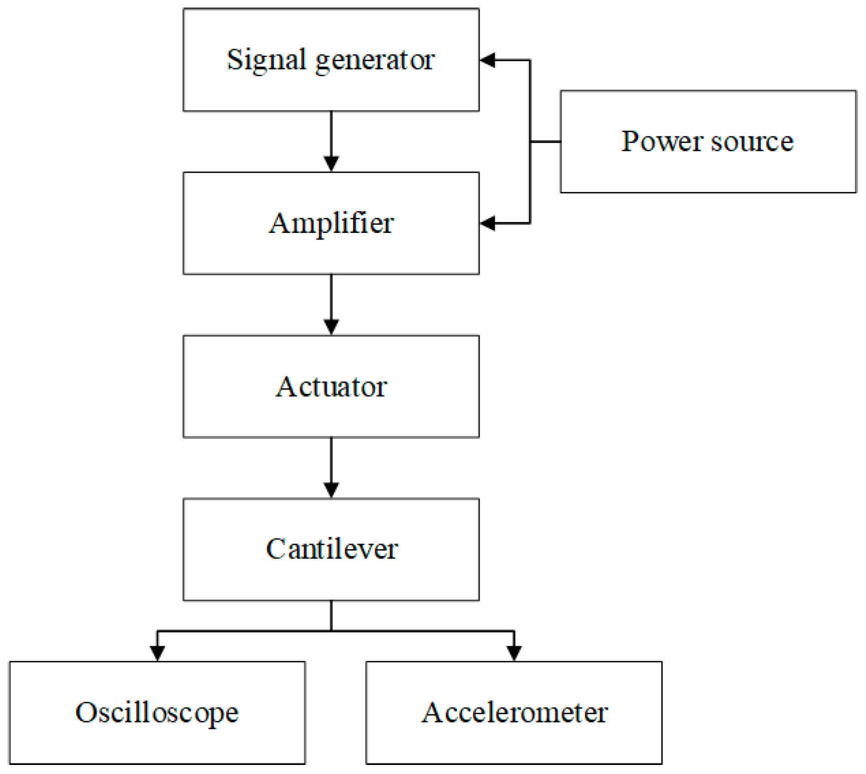
As shown in Figure 2, a signal generator outputs a specific frequency signal, which, after amplification, is used to excite the actuator to vibrate. The cantilever is fixed on the actuator. An oscilloscope and multimeter are used to measure the peak-to-peak and root mean square (RMS) values of the output voltage, respectively.
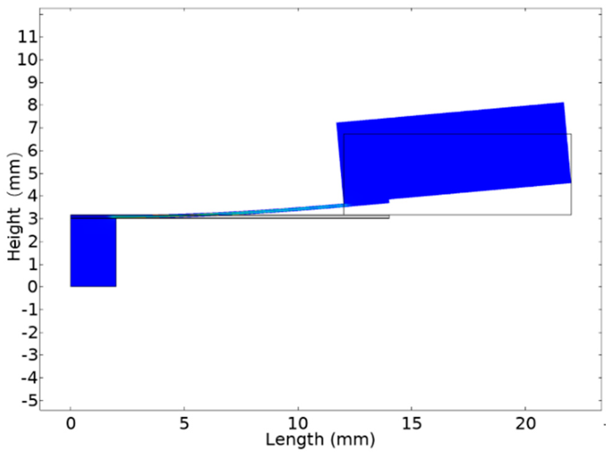
Figure 3 shows a schematic diagram of a modeled piezoelectric converter, and Table 1 shows the main parameters that were used for global definitions in the COMSOL Multiphysics simulation software. The piezoelectric energy harvester consists of a base of passive material (e.g., steel) with active layers of piezoelectric material attached to it by conductive electrodes. The mechanical effects of the electrodes on the system have not been evaluated due to their extremely small thickness compared to the overall thickness of the transducer. It is assumed that the substrate and the layer of piezoelectric material are perfectly coupled, and that the electrodes are ideally conductive and exposed to the same difference of electric potential.
The virtual interface between the piezoelectric power converter and the external electrical circuit was realized using a SPICE electrical circuit simulation subroutine, in which the resistor was inserted as a variable (i.e., a variable impedance element) into the finite element model (FEM) model of the converter. A complex model of a vibrating electric converter was constructed, which evaluates the mutual electromechanical interaction between the piezoelectric converter and the connected electrical circuit.
PVDF was selected as the piezoelectric material for its high dielectric constant and piezoelectric coefficient. The PVDF film used is 30 μm thick, with a thin Al electrode on the surface, and bonded in the same polling and stretching directions. The main parameters of PVDF are shown in Table 2. Structural steel was chosen as both the metal substrate and proof mass.
The piezoelectric energy harvester was subjected to a selected kinematic excitation, which is described as a vertical or volumetric displacement of a volumetric load. Therefore, the piezoelectric energy harvester was excited and the active piezo-layers generated a voltage signal.
According to the design parameters above, the 2D finite element model (FEM) of a vibratory piezoelectric power converter was built using COMSOL Multiphysics software, as shown in Figure 3. For numerical studies, solid mechanics, electrostatics, and electrical circuits are the physics used along with the study of frequency domain in COMSOL Multiphysics.
The described FEM model of the piezoelectric energy harvester (Figure 4) allows for a complex evaluation of the transducer response, the electromechanical interaction of the energy harvester with the external electrical circuit, and the effects of nonlinear dynamics occurring in the vibrating mode of the harvester. The influence of the energy harvester excitation signal, energy harvester geometric configurations and shape variations, piezoelectric material layer thickness, connected electrical circuit resistance on the energy harvester dynamic, and electrical response was evaluated using the developed piezoelectric FEM model.
The strain–charge constitutive relation is shown in Equations (1) and (2) [11]:
S = SE × T + dT × E,
D = d × T + εT × T,
where T—stress; S—strain; D—electric displacement; d—the piezoelectric coefficient matrix; ε—the permittivity matrix.
In general, there are two types of mathematical modeling for piezoelectric energy harvesters. The first one is a lumped parameter electromechanical model, the second one is a distributed parameter model. A compressive mathematical model should be as simple as possible, yet sophisticated enough to capture the important phenomena. In our case, the proof mass is much larger than the mass of a cantilevered beam in transverse vibrations (the harvester model in 31-mode). Therefore, the lumped parameter mathematical model can be adopted, which can be given as:
v ( t )   =   j R θ m e ω 3 Y o e j ω t ( ω n L 2 ω 2 + j 2 ζ ω n L ω ) × ( m e + j m e R C p ω ) + j R θ 2 ω
where me is the effective mass of the beam, ω n L is the un-damped natural frequency, ζ is the mechanical damping ratio, R is the load resistance, and θ is the electromechanical coupling factor given by 2d31hps(kbL2)/(2I) for parallel connections of piezoelectric layers. Cp is the equivalent capacitance that can be given by 2 ε 33 S (bL)/hp, hs and hp are the thickness of substrate and piezoelectric layers, respectively, hps = (hs + hp)/2, ε 33 S is the permittivity at constant strain, d31 is the piezoelectric constant, and b is the width of the beam [35].
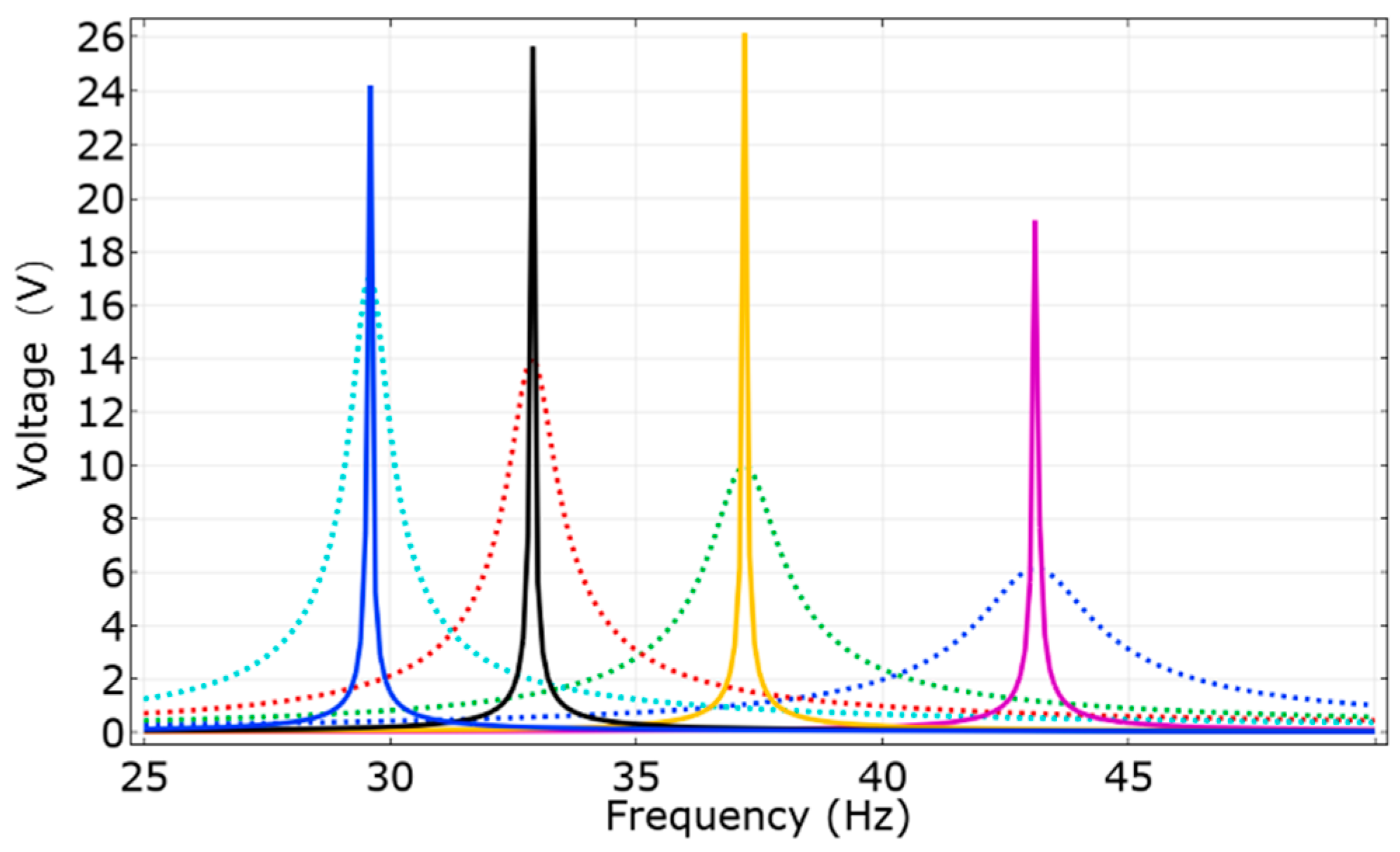
As we can see from Equation (3), the mechanical damping has a direct influence on the output voltage. The results obtained when modeling a multilayer piezoelectric energy harvester using only the loss factor η are compared to the results obtained using the Rayleigh damping coefficient (Figure 5) [36]. The latter is more advantageous and accurate in a dynamic response analysis as it provides a clear physical meaning of the whole system. In most publications on the modeling of piezoelectric transducers, frequency data and modeling results are provided using only the loss factor [37,38].
The loss factor is a way to compare the damping of one material to another and it is independent of the geometrical parameters of the structure as it just depends on the material; however, the geometrical parameters of the beam do affect the damping and the output voltage. As can be seen in Figure 5, the result of the output voltage using the loss factor is 50% higher than the real result, which is a theoretical value instead of a practical value. Therefore, to evaluate the damping of the whole structure, Rayleigh damping is an effective way as it considers the damping of the whole structure, which is implemented in the present work.
To describe the FEM model, it is necessary to know not only the material properties but also the damping ratio of the multilayer system. For this, experimental studies were carried out. Using the previous modeling results, the boundary conditions of the cantilever dimensions were obtained, from which the dependence of the system damping coefficient on the length, width, and load mass of the cantilever was experimentally determined.

2.2. Measurements of Young’s Modulus and Rayleigh Damping Coefficient

The Young modulus (E) of a material is an important parameter for piezoelectric harvester design. In most cases, approximations and simulated values are sufficient, but when designing a precise and efficient piezoelectric cantilever with optimal parameters, a more cautious assessment is in order [39].
In the case of the mechanical design of the elastic piezoelectric energy harvester cantilever structures, the default Young modulus value of steel cannot be used directly, as the piezoelectric material layer sticks to the steel, which causes the change of its practical value.
To determine the practical Young modulus value, a cantilever beam is fixed at one end and is free to move vertically at the other, as shown in Figure 6.
For each of the three strips of material (steel, glue, piezoelectric material), the strip is clamped at one end so that it extends horizontally, with the plane of the strip parallel to the plane of the bench. A small weight is hung on the free end and the vertical displacement, δ, is measured. The value of δ is related to the applied load, P, and Young’s modulus, E, by
E = 1/3 × (P × L3)/(δ × I),
where L is the length of the strip and I is the second moment of area (moment of inertia).
For a prismatic beam with a rectangular section (depth h and width w), the value of I is given by
I = (w × h3)/12.
By hanging several different weights on the end of the strip, and measuring the corresponding deflections, a graph can be plotted which allows the Young modulus to be calculated.
According to the theory above, the practical Young modulus value of the piezoelectric energy harvester cantilever beam can be calculated. The deflection of a core layer of the piezoelectric energy harvester cantilever is measured by attaching four different kinds of weights at the end, as shown in Figure 7.
Based on the geometric parameters of the energy harvester in Table 1 and the measurements of Figure 7, the Young modulus in this case is calculated as E = 15.46 × 10¹⁰ Pa.
Damping is the mechanism by which a system’s kinetic energy is gradually converted into heat or sound. Due to the reduction in energy, damping has the effect of gradually reducing the system’s response, e.g., the displacement amplitude. Thus, in many cases, damping is a beneficial phenomenon without which the system may remain in a state of chaos indefinitely.
Rayleigh damping, known as a proportional damping or classical damping model, expresses damping as a linear combination of the mass and stiffness matrices [40], that is
C = αM + βK,
where M—mass matric; K—stiffness matric; α and β—real scalars with 1/s and s units, respectively. Modes of classically damped systems preserve the simplicity of the real normal modes.
To determine Rayleigh damping, it is usually recommended that the two specific frequencies ω1 and ω2, to ensure reasonable damping values in all the modes, significantly contribute to the vibrations. At the frequency outside the range of these two frequencies, the damping will dramatically increase and the modal responses at the corresponding frequency range will be almost eliminated. Practically, this can be used to damp out the high and low frequency vibrations/noises that are outside the frequency range of interest. The relations of Rayleigh damping coefficients α, β, damping ratio ς, and two specific frequencies ω1 and ω2 are shown in Equation (7)
[α, β] = 2ς/(ω1 + ω2) × [ω1 × ω2, 1]
The Q factor describes an underdamped oscillator. One of the Q factor definitions is the frequency-to-bandwidth ratio of the resonator
Q = ωr/(ω2ω1),
where ωr is the resonant frequency, and ω2ω1 is the bandwidth, or the width of the range of frequencies for which the energy is half of its peak value.
The relationship between the Q factor and damping ratio is shown in Equation (9)
ς = 1/2 × Q.
In order to simulate the model, we measured the damping ratio and calculated the Rayleigh damping coefficients α and β.
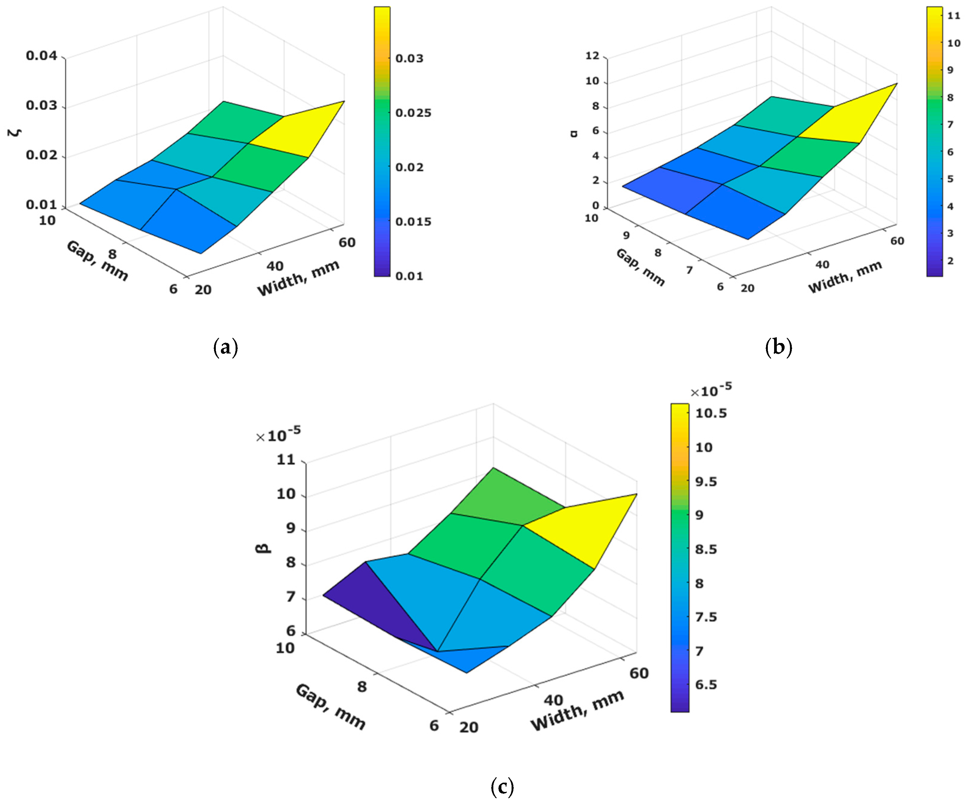
We designed five kinds of energy harvester cantilever with different widths of PVDF material, ranging from 24 to 64 mm. According to the theoretical description of Rayleigh damping, we need to measure the peak-to-peak value of output voltage under the resonant frequency. Based on the peak-to-peak value, we can measure another two frequencies, in which the output power is half of the value measured under resonant frequency.
As shown in Figure 8, the result reflects that the energy harvester is a linear vibration system. According to these data, the damping coefficient of different gaps and widths can be approximately calculated using empirical approximation.

2.3. Simulation Implementation and Results

According to the geometry dimensions of the practical piezoelectric energy harvester cantilever beam, a 2D model is built to simulate in COMSOL. The electrical circuit is connected based on the practical model. Since the damping ratio will change while changing the other variables, a parametric sweep method is used for the study. The parametric sweep can handle several parameter cases together and accomplish the work simultaneously. In this case, the proof mass and gap change with the damping coefficients, respectively.
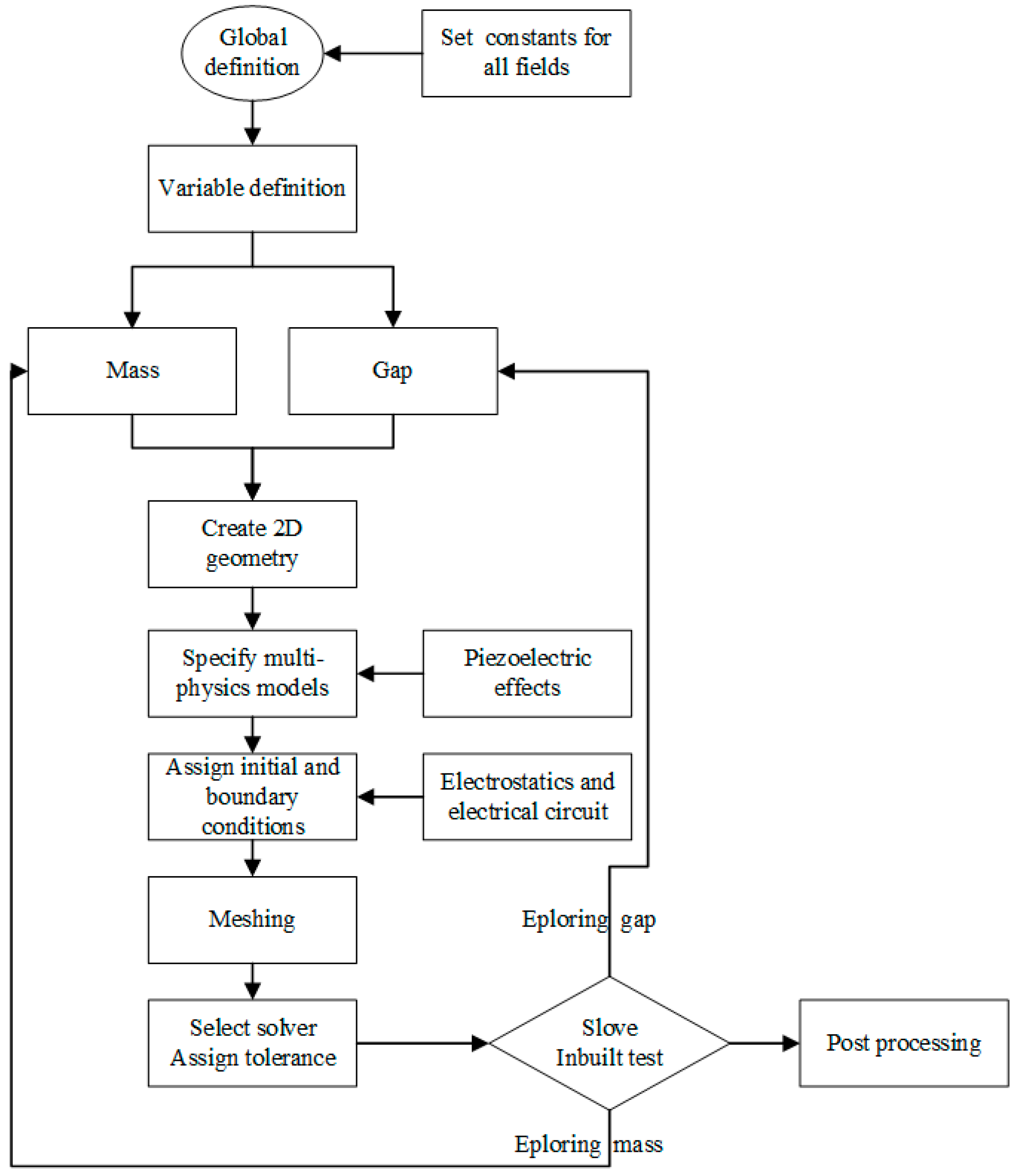
The whole implementation procedure of the piezoelectric devices’ modeling for energy harvester in COMSOL is shown in Figure 9. When we want to explore the gap between the clamped end and the proof mass, we need to keep the proof mass stable and change the gap. Similarly, if exploring the factor of the proof mass, we need to keep the gap constant.
Using the dependence of the damping coefficient of the inverter on its length, width, and load masses, FEM modeling was performed. The pulsed excitation signal is described in the FEM model as a vertical load volume. The change of the effective voltage generated by the piezoelectric converter depending on the energy harvester parameters is recorded. Figure 10 gives the voltage as a function of the PVDF width under uniform load (15.2 g).
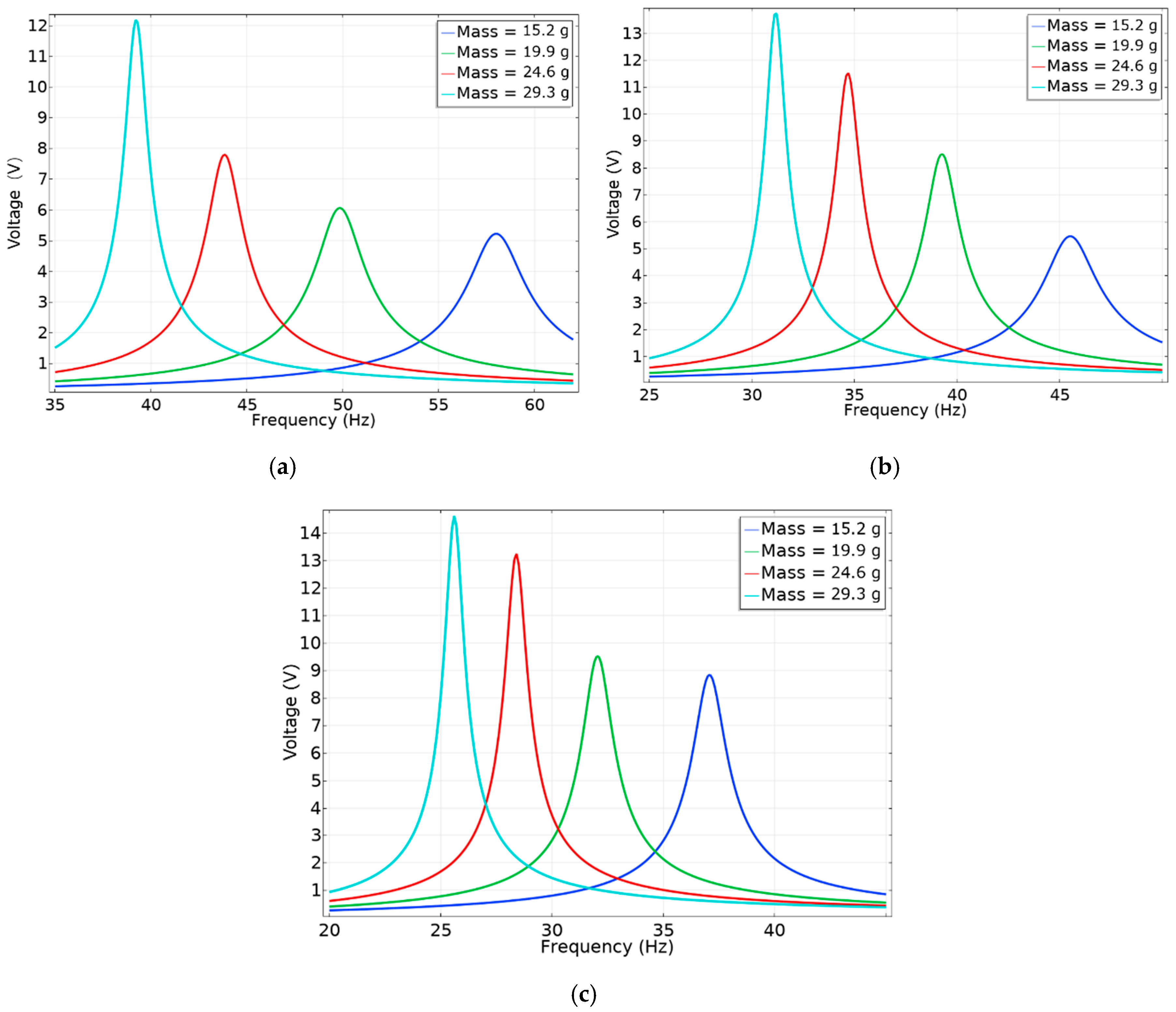
The dependences of the gap and the proof mass on the output voltage of the structure are simulated. A load resistance of 470 Ω is selected. In order to analyze the effects of the proof mass and gaps, we simulated four kinds of masses and three kinds of gaps. To be comparable, mass and gap are kept stable in each simulation.
The voltage–frequency response curves of different masses are shown in Figure 11.
It can be seen from these figures that by increasing the gap, it is possible to obtain higher energy efficiency, but the resonant frequency decreases.

3. Experimental Results and Discussion

In order to validate the simulation results, experiments were carried out. In Figure 12, the experimental voltage data of the PVDF energy harvester cantilever are compared against the simulated voltage data at resonant frequency.
As can be seen in Figure 9, the systems oscillate following the typical response characteristics of linear vibration systems. The values of simulated voltage and measured voltage are fitted well. The differences between simulation and measurement resonant frequency are no more than 4 Hz. The practical cantilever model is built by hand, with manually adjusting parameters, like gaps, and some tolerance exists. In contrast, in numerical analysis, there could be no error. Furthermore, the thickness of the glue used to stick the piezoelectric layers together could also affect the results. Perhaps this could be one of the main reasons for the difference in the simulated and practical values as the thickness of the layer of glue applied in the practical model is challenging to measure. In future works, these differences can be analyzed in more depth. It can also be seen in these three figures that with the mass increasing, the output voltage increases in both simulation and experimental data.
To identify how the gaps affect the output voltage, we compared the output value of different gaps. The results reflect changes of the output voltage with gaps. As the gap becomes bigger, the output voltage increases. According to the experimental data, the output voltage measured with the maximum gap and mass is about 5 times the voltage measured with the minimum gap and mass. Clearly, increasing the proof mass and gap can improve the output voltage and decrease resonant frequency.

4. Conclusions

In order to have a better optimized output, simulation results using Rayleigh damping prove to be more accurate compared to the loss factor results. According to our tests, simulation results using loss factor differ from the actual value by 50%, which clearly shows that it is not the best suitable model to define a cantilever harvester. However, the model created by the Rayleigh damping overcomes the shortcomings present in the loss factor model by considering the virtue of mechanical damping in the practical models.
A more accurate model and simulation was built in the COMSOL Multiphysics simulation software based on the measurements of Rayleigh damping coefficients. The COMSOL simulation results are compared with the experiment data. As expected, the simulation results follow the theoretical ones.
Experimental determination of Rayleigh Damping coefficients, linear approximation, and modeling of the cantilever give results with sufficient error (up to 10%).
According to both experimental and simulation data, increasing the gap and proof mass increases the output voltage. Under the conditions of 0.4 g acceleration, 10 mm gap, and 29.3 g proof mass, the output voltage and power can rise to 14.6 V and 435 μW, respectively. Comparing with the smallest gap and proof mass, proper piezoelectric energy harvester optimization can increase a voltage output up to 5 times.

Author Contributions

Conceptualization: V.M., D.N., A.V. and D.A.; methodology: D.A. and V.M.; software: D.N., M.C. and A.M.; validation: C.R., B.P., A.V., N.D., A.M. and M.Z.; visualization: M.C., B.P., C.R., M.Z., N.D. and N.H.; investigation: M.C., C.R., B.P., V.M., N.D., D.N., D.A., A.V. and M.Z.; resources: D.N., V.M. and A.M.; data curation: M.C. and D.N.; writing—original draft preparation: M.C., B.P., C.R., D.A., A.M. and A.V.; writing—review and editing: B.P., M.Z., D.N., D.A., N.D. and N.H.; supervision: V.M. and D.A.; project administration: V.M. and D.A.; funding acquisition: A.V., N.H. and M.Z. All authors have read and agreed to the published version of the manuscript.

Funding

This research received no external funding.

Conflicts of Interest

The authors declare no conflict of interest.

References

  1. Roundy, S.; Wright, P.K. A piezoelectric vibration based generator for wireless electronics. Smart Mater. Struct. 2004, 13, 1131–1142. [Google Scholar] [CrossRef] [Green Version]
  2. Sue, C.-Y.; Tsai, N.-C. Human powered MEMS-based energy harvest devices. Appl. Energy 2012, 93, 390–403. [Google Scholar] [CrossRef]
  3. Chaudhuri, D.; Kundu, S.; Chattoraj, N. Design and analysis of MEMS based piezoelectric energy harvester for machine monitoring application. Microsyst. Technol. 2019, 25, 1437–1446. [Google Scholar] [CrossRef]
  4. Safaei, M.; Sodano, H.A.; Anton, S.R. A review of energy harvesting using piezoelectric materials: State-of-the-art a decade later (2008–2018). Smart Mater. Struct. 2019, 28, 113001. [Google Scholar] [CrossRef]
  5. Liu, H.; Lee, C.; Kobayashi, T.; Tay, C.J. Investigation of a MEMS piezoelectric energy harvester system with a mechanism introduced by mechanical stoppers. Smart Mater. Struct. 2012, 21, 035005. [Google Scholar] [CrossRef]
  6. Cook-Chennault, K.A.; Thambi, N.; Sastry, A.M. Powering MEMS portable devices—A review of non-regenerative and regenerative power supply systems with special emphasis on piezoelectric energy harvesting systems. Smart Mater. Struct. 2008, 17, 043001. [Google Scholar] [CrossRef] [Green Version]
  7. Wang, P.; Du, H. ZnO thin film piezoelectric MEMS vibration energy harvesters with two piezoelectric elements for higher output performance. Rev. Sci. Instrum. 2015, 86, 075002. [Google Scholar] [CrossRef]
  8. Guyomar, D.; Sebald, G.; Pruvost, S.; Lallart, M.; Khodayari, A.; Richard, C. Energy harvesting from ambient vibrations and heat. J. Intell. Mater. Syst. Struct. 2008, 20, 609–624. [Google Scholar] [CrossRef]
  9. Ahmed, R.; Mir, F.; Banerjee, S. A review on energy harvesting approaches for renewable energies from ambient vibrations and acoustic waves using piezoelectricity. Smart Mater. Struct. 2017, 26, 085031. [Google Scholar] [CrossRef]
  10. Yang, Z.; Wang, Y.Q.; Zuo, L.; Zu, J. Introducing arc-shaped piezoelectric elements into energy harvesters. Energy Convers. Manag. 2017, 148, 260–266. [Google Scholar] [CrossRef]
  11. Montazer, B.; Sarma, U. Design and optimization of quadrilateral shaped PVDF cantilever for efficient conversion of energy from ambient vibration. IEEE Sens. J. 2018, 18, 3977–3988. [Google Scholar] [CrossRef]
  12. Pradeesh, E.L.; Udhayakumar, S. Investigation on the geometry of beams for piezoelectric energy harvester. Microsyst. Technol. 2018, 25, 3463–3475. [Google Scholar] [CrossRef]
  13. Andriukaitis, D.; Anilionis, R. Investigation of Etching Process in Nano Structures. Elektron. Elektrotech. 2008, 86, 77–80. [Google Scholar]
  14. Bakhtiari-Shahri, M.; Moeenfard, H. Energy harvesting from unimorph piezoelectric circular plates under random acoustic and base acceleration excitations. Mech. Syst. Signal Process. 2019, 130, 502–523. [Google Scholar] [CrossRef]
  15. Zhao, Q.; Liu, Y.; Wang, L.; Yang, H.; Cao, D. Design method for piezoelectric cantilever beam structure under low frequency condition. Int. J. Pavement Res. Technol. 2018, 11, 153–159. [Google Scholar] [CrossRef]
  16. Izadgoshasb, I.; Lim, Y.Y.; Lake, N.; Tang, L.; Padilla, R.V.; Kashiwao, T. Optimizing orientation of piezoelectric cantilever beam for harvesting energy from human walking. Energy Convers. Manag. 2018, 161, 66–73. [Google Scholar] [CrossRef]
  17. Prauzek, M.; Konecny, J.; Vitasek, M.; Bajgar, V.; Musilek, P. Powering Batteryless Embedded Platforms by Piezoelectric Transducers: A Pilot Study. Elektron. Elektrotech. 2019, 25, 32–35. [Google Scholar] [CrossRef] [Green Version]
  18. Uzun, Y.; Demirbas, S.; Kurt, E. Implementation of a New Contactless Piezoelectric Wind Energy Harvester to a Wireless Weather Station. Elektron. Elektrotech. 2014, 20, 35–39. [Google Scholar] [CrossRef]
  19. Erturk, A.; Inman, D.J. Piezoelectric Energy Harvesting, 1st ed.; Wiley: London, UK, 2011. [Google Scholar]
  20. Sriramdas, R.; Chiplunkar, S.; Cuduvally, R.M.; Pratap, R. Performance Enhancement of Piezoelectric Energy Harvesters Using Multilayer and Multistep Beam Configurations. IEEE Sens. J. 2015, 15, 3338–3348. [Google Scholar] [CrossRef]
  21. Dayou, J.; Liew, W.; Chow, M.-S. Increasing the bandwidth of the width-split piezoelectric energy harvester. Microelectron. J. 2012, 43, 484–491. [Google Scholar] [CrossRef]
  22. Sang, C.M.; Dayou, J.; Liew, W.Y.H. Increasing the output from piezoelectric energy harvester using width-split method with verification. Int. J. Precis. Eng. Manuf. 2013, 14, 2149–2155. [Google Scholar] [CrossRef]
  23. Chen, N.; Jung, H.J.; Jabbar, H.; Sung, T.H.; Wei, T. A piezoelectric impact-induced vibration cantilever energy harvester from speed bump with a low-power power management circuit. Sens. Actuators A Phys. 2017, 254, 134–144. [Google Scholar] [CrossRef]
  24. Khan, M.B.; Kim, D.H.; Han, J.H.; Saif, H.; Lee, H.; Lee, Y.; Kim, M.; Jang, E.; Hong, S.K.; Joe, D.J.; et al. Performance improvement of flexible piezoelectric energy harvester for irregular human motion with energy extraction enhancement circuit. Nano Energy 2019, 58, 211–219. [Google Scholar] [CrossRef]
  25. Kong, N.; Ha, D.S.; Erturk, A.; Inman, D.J. Resistive Impedance Matching Circuit for Piezoelectric Energy Harvesting. J. Intell. Mater. Syst. Struct. 2010, 21, 1293–1302. [Google Scholar] [CrossRef]
  26. Yun, J.; Patel, S.N.; Reynolds, M.S.; Abowd, G.D. Design and performance of an optimal inertial power harvester for human-powered devices. IEEE Trans. Mob. Comput. 2010, 10, 669–683. [Google Scholar] [CrossRef]
  27. Sheeraz, M.A.; Butt, Z.; Khan, A.M.; Mehmood, S.; Ali, A.; Azeem, M.; Nasir, A.; Imtiaz, T. Design and Optimization of Piezoelectric Transducer (PZT-5H Stack). J. Electron. Mater. 2019, 48, 6487–6502. [Google Scholar] [CrossRef]
  28. Chen, N.; Bedekar, V. Modeling, Simulation and Optimization of Piezoelectric Bimorph Transducer for Broadband Vibration Energy Harvesting. J. Mater. Sci. Res. 2017, 6, 5. [Google Scholar] [CrossRef] [Green Version]
  29. Song, J.; Zhao, G.; Li, B.; Wang, J. Design optimization of PVDF-based piezoelectric energy harvesters. Heliyon 2017, 3, e00377. [Google Scholar] [CrossRef]
  30. Alsaadi, N.; Sheeraz, M.A. Design and optimization of bimorph energy harvester based on Taguchi and ANOVA approaches. Alex. Eng. J. 2020, 59, 117–127. [Google Scholar] [CrossRef]
  31. Hanif, N.H.H.M.; Mohaideen, A.J.; Azam, H.; Rohaimi, M.E. Rotational piezoelectric energy harvester for wearable devices. Cogent Eng. 2018, 5, 1430497. [Google Scholar] [CrossRef]
  32. Jasim, A.; Yesner, G.; Wang, H.; Safari, A.; Maher, A.; Basily, B. Laboratory testing and numerical simulation of piezoelectric energy harvester for roadway applications. Appl. Energy 2018, 224, 438–447. [Google Scholar] [CrossRef]
  33. Fernandes, E.; Martin, B.; Rua, I.; Zarabi, S.; Debéda, H.; Nairn, D.; Wei, L.; Salehian, A. Design, fabrication, and testing of a low frequency MEMS piezoelectromagnetic energy harvester. Smart Mater. Struct. 2018, 27, 035017. [Google Scholar] [CrossRef]
  34. Lu, C.; Raghunathan, V.; Roy, K. Efficient Design of Micro-Scale Energy Harvesting Systems. IEEE J. Emerg. Sel. Top. Circuits Syst. 2011, 1, 254–266. [Google Scholar] [CrossRef]
  35. Baishya, S.; Borthakur, D.; Kashyap, R.; Chatterjee, A. A high precision lumped parameter model for piezoelectric energy harvesters. IEEE Sens. J. 2017, 17, 8350–8355. [Google Scholar] [CrossRef]
  36. Baker, J.W. Evaluation of Rayleigh damping and its influence on engineering demand parameter estimates. In Proceedings of the 8th Pacific Conference on Earthquake Engineering, Singapore, 5–7 December 2007; pp. 1–6. [Google Scholar]
  37. Wang, L.; Zhao, L.; Jiang, Z.; Luo, G.; Yang, P.; Han, X.; Li, X.; Maeda, R. High accuracy comsol simulation method of bimorph cantilever for piezoelectric vibration energy harvesting. AIP Adv. 2019, 9, 095067. [Google Scholar] [CrossRef]
  38. Thein, C.K.; Ooi, B.L.; Liu, J.S.; Gilbert, J.M. Modelling and optimisation of a bimorph piezoelectric cantilever beam in an energy harvesting application. J. Eng. Sci. Technol. 2016, 11, 212–227. [Google Scholar]
  39. Hopcroft, M.A.; Nix, W.D.; Kenny, T.W. What is the Young’s Modulus of Silicon? J. Microelectromech. Syst. 2010, 19, 229–238. [Google Scholar] [CrossRef] [Green Version]
  40. Trombetti, T.; Silvestri, S. On the modal damping ratios of shear-type structures equipped with Rayleigh damping systems. J. Sound Vib. 2006, 292, 21–58. [Google Scholar] [CrossRef]
Figure 1. Equivalent electromechanical circuit of a piezoelectric energy harvester.
Electronics 09 02030 g001
Figure 2. The experimental setup.
Electronics 09 02030 g002
Figure 3. A reference layout of the piezoelectric energy harvester cantilever.
Electronics 09 02030 g003
Figure 4. COMSOL finite models of piezoelectric energy harvester cantilever.
Electronics 09 02030 g004
Figure 5. Voltage–frequency response of a piezoelectric biomorph cantilever using the loss factor. Uniform line shows the results with the loss factor, the dotted line—using the Rayleigh damping coefficient.
Electronics 09 02030 g005
Figure 6. Geometry of the cantilever beam test.
Electronics 09 02030 g006
Figure 7. Results of the relation between load and deflection.
Electronics 09 02030 g007
Figure 8. Results of damping coefficients: (a) damping ratio ς, (b) Rayleigh damping coefficient of α, (c) Rayleigh damping coefficient of β.
Electronics 09 02030 g008
Figure 9. Implementation procedure of modeling in COMSOL.
Electronics 09 02030 g009
Figure 10. The voltage–frequency response curves of different width of PVDF.
Electronics 09 02030 g010
Figure 11. Simulation result of voltage–frequency response curves of different mass: (a) gap is 6 mm, (b) gap is 8 mm, (c) gap is 10 mm.
Electronics 09 02030 g011
Figure 12. Experimental and simulated voltage data with different masses: (a) gap is 6 mm, (b) gap is 8 mm, (c) gap is 10 mm.
Electronics 09 02030 g012
Table 1. Geometric parameters of the energy harvester cantilever model.
ParametersSymbolsValues
Dimensions of fixed end (mm)Lm × Wm × tm3 × 3 × 3
Dimensions of PVDF film (mm)Le × Wb × tb14 × (24–64) × 0.03
Dimensions of steel (mm)Le × Wb × ts14 × (24–64) × 0.1
Dimensions of proof mass (mm)Lm × Wm14 × (24–64)
Weight of mass (g)M15–30
Gaps (mm)L5–10
Table 2. Parameters of energy harvester material.
Piezoelectric Material: PVDF (JINZHOUKEXIN Co. Ltd.)
Piezoelectric constant (pC/N)d3125
Young’s modulus (MPa/psi)E2500
Relative permittivityε/ε09.5
Density (kg/m3)ρb1780
Thickness (μm)tb30
Publisher’s Note: MDPI stays neutral with regard to jurisdictional claims in published maps and institutional affiliations.