Review

Evaluation of Quadrature Signal Generation Methods with Reduced Computational Resources for Grid Synchronization of Single-Phase Power Converters through Phase-Locked Loops

1
Escuela Superior de Ingeniería y Tecnología, Universidad Internacional de La Rioja, 26006 Logroño, La Rioja, Spain
2
Escuela Técnica Superior de Náutica, Universidad de Cantabria, 39005 Santander, Cantabria, Spain
3
Escuela Técnica Superior de Ingenieros Industriales y de Telecomunicación, Universidad de Cantabria, 39005 Santander, Cantabria, Spain
*
Author to whom correspondence should be addressed.
Electronics 2020, 9(12), 2026; https://doi.org/10.3390/electronics9122026
Submission received: 28 October 2020 / Revised: 21 November 2020 / Accepted: 25 November 2020 / Published: 30 November 2020
(This article belongs to the Special Issue Digital Control in Power Electronics)

Abstract

:
Low-cost single-phase grid connected converters require synchronization with the grid voltage to obtain a better response and protection under diverse conditions, such as frequency perturbations and distortion. Phase-locked loops (PLLs) have been used in this scenario. This paper describes a set of quadrature signal generators for single-phase PLLs; compares the performances by means of simulation tests considering diverse operation conditions of the electrical grid; proposes strategies to reduce the computational burden, considering fixed-point digital implementations; and provides both descriptive and quantitative comparisons of the required mathematical operations and memory units for implementation of the analyzed single-phase PLLs.

1. Introduction

In recent years, there has been a considerable increase in the presence of power converters in the electrical grid due to the diversification of sources, storage systems and loads as well as the fulfilment of the applicable standards [1]. Electrical grids are losing inertia [2], thus, the term grid-following converter used for stiff grids gives way to the term grid-forming converter for low inertia grids in which the control becomes more challenging to ensure the proper power quality indexes. Front-end power converters and smart transformers [3] are used to supply many electrical loads. Some relevant examples are the charging points for electric vehicles [4] and the power supply for railway transportation [5]. The raising of renewable generation such as photovoltaic [6] and wind [1] along with energy storage plants [7] also benefits from the power converter interfaces. The energy distribution systems also leverage their capabilities.
Even though the use of self-synchronized converters in certain applications, which eliminates the need for a dedicated synchronizer, results in a simpler and more robust controller [8], in most applications, the active synchronization enables complementary functions that go beyond the basic current control functions, e.g., providing a measure of grid frequency/voltage for anti-island methods [9,10]. This is where synchronization strategies, especially phase-locked loops (PLLs), can play a key role in improving the phase and, therefore, the current reference generation.
The synchronization circuit tracks the grid phase corresponding to the positive sequence fundamental of the voltage at the connection point and should maintain this synchronization during disturbances.
Modern active rectifiers connected to low-voltage (LV) grids avoid the diode rectification stage to increase the overall efficiency. Currently, it is necessary to take into account not only the power factor [11] but also the effect on the LV grid and neighboring loads, with the use of voltage/frequency regulation functions [12], ride-through capabilities [13], etc.
In this work, after the introduction, a classification of PLLs according to the generation technique of the phase reference is presented in Section 2. In Section 3, examination of the state of the art of PLLs with quadrature signal generation (QSG) used in single-phase power electronic converters is carried out. An in-depth study of the building blocks identifying the pros and cons of each of them is presented. Additionally, the strategies are evaluated in simulation using the Monte Carlo method, and its computational burden is compared at both descriptive and implementation levels considering a digital device with fixed-point arithmetic. Finally, the conclusions of the work are presented.

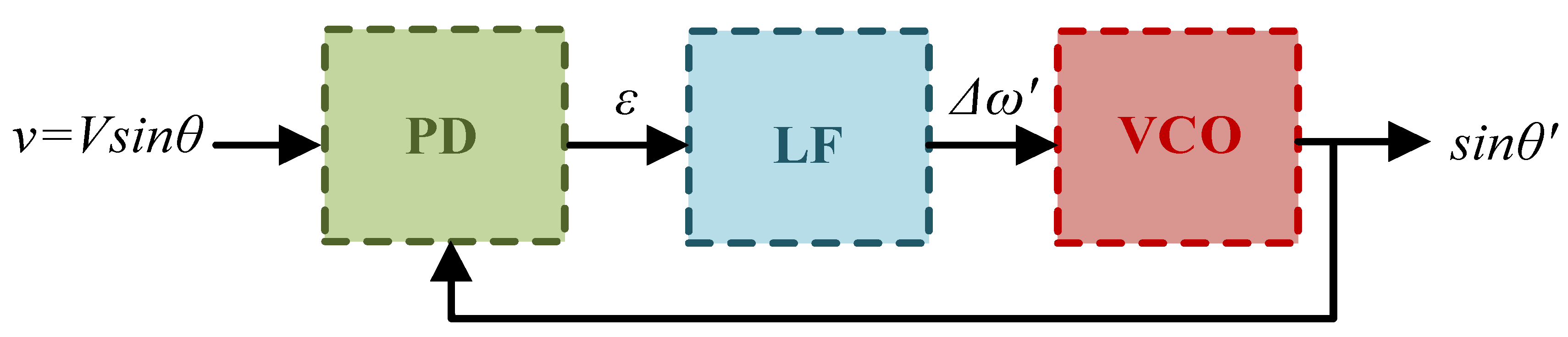
2. Principle of Operation and Types of PLLs

The PLL operates in closed-loop, generating an output signal around the center frequency in-phase with an input signal [14,15]. Once the PLL is locked, the circuit also tracks the grid frequency.
The basic structure of a PLL consists of three functional blocks [15], as seen in Figure 1: a phase detector (PD), a loop filter (LF) and a voltage-controlled oscillator (VCO) [16]. The phase detector compares the phase of the PLL with that of the grid, providing an error signal, ε, whose direct current (DC) component corresponds to the phase error. The filter attenuates other frequency components present in that error signal, which is carried out usually through a first-order low-pass filter. The LF output, Δ ω , provides an estimation of the frequency deviation of the PLL from its nominal oscillation frequency, ω 0 , which allows the VCO to generate a periodic signal of frequency ω = ω 0 + Δ ω , typically a sinusoidal one in grid-connected power converters. When the PLL is locked, it is in-phase with the grid voltage (θ≈ θ) and provides a frequency estimation, ω , approximately matching that of the grid ( ω ω ).
The definitions of the LF and VCO transfer functions, LF (z) and VCO (z), depend on the design goals of the PLL and the application in which it is used.
The response time, overshooting and the steady-state error of the PLL depend on the characteristics of the selected functional blocks as well as the effect of noise, disturbances and events in the electrical grid [17] that modify the waveform of the grid voltage.
Although a zero-order LF is the simplest approach, it is unable to follow phase ramps or frequency variations [17]. First-order LFs achieve monitoring of the grid phase during slow-frequency variation events, thus, they are very widespread in synchronization of grid-connected converters [1]. On the other hand, higher-order LFs are capable of tracking grid frequency variations, and they are especially interesting to attenuate harmonics. This is the case of [18,19,20], where a second-order LF is used to withstand large variations in voltage and frequency. Similarly, adaptive filters have also been embedded within the PLL structure to filter out the harmonic distortion. An example of this type of implementation is shown in [20], where the design of an adaptive comb filter with an even-order harmonic filtering capacity is proposed. While in [21], the implementation of several adaptive notch filters is proposed. These techniques slightly affect the dynamic response of the PLL and significantly increase the associated computational burden.
The VCO generates the periodic signal used by the phase detector. In analog PLLs, this block is a dedicated circuit controlled by the output voltage of the LF [3], but in the digital versions used in current power electronic converters, the controlled oscillator is realized with look-up tables (LUTs), the coordinate rotation digital computer (CORDIC) or the digitally controlled oscillator (DCO). The LUTs, as in [22], occupy large memory resources either implemented in a field-programmable gate array (FPGA) or in digital signal processors (DSP). The use of CORDIC algorithms [23] adds complexity and slows down the execution of PLL circuits. This solution increases the precision obtained compared with the LUTs in return for increasing the computational burden of the system. In [24], the use of CORDIC algorithms is proposed to implement different mathematical functions in addition to the sine and cosine of the phase estimated by the PLL. While [25] uses a scheme that combines CORDIC and the LUT which, due to the symmetric characteristic of the sine and cosine function, only the information of a quarter of a period is included. Moreover, in [26,27], DCOs are implemented in a fixed-point DSP. As an example, in Figure 2, the structure of the proposed DCO is presented.
Considering the operation principle of the phase detector (PD), PLLs are classified into three categories [1]: enhanced PLLs (EPLLs), power-based PLLs (pPLLs) and PLLs with quadrature signal generation (QSG PLLs). The EPLL [28] is based on an adaptive LF, which reconstructs the input signal by estimating the amplitude and phase angle provided by the VCO of the PLL [29]. The EPLL has the handicap of introducing a π/2 phase shift [30]. The PDs of the pPLLs using the pq theory [31] are designed for three-phase systems. However, it is possible to implement them in single phase PLLs with active filters [32,33,34]. The output signal of these PDs in pPLLs has a term around , which is difficult to filter with the LF, causing oscillations in the phase error signal. Additionally, certain controllers in converters connected to the grid require information on the voltage amplitude and, in pPLLs, this is not directly available. The effect of the term at the PD output on the behavior of the first-order LF can be reduced by adopting a PD that cancels that oscillatory term and shifts the PD ripple to a higher frequency. Such is the case of PLLs based on the Park transformation. This block is widely adopted due to its balance between simplicity and performance when the electrical grid corresponds to a balanced three-phase system in a sinusoidal operating regime. Since the Park transformation requires three-phase signals or their representation in the complex stationary reference frame through the Clarke transformation, in the case of single-phase power converters, a QSG is used to generate the βk signal from the grid voltage signal (it is considered as αk, and the homopolar component is set to zero). There are different ways to build the QSG. The most commonly used are described below.
Table 1 compares the computational burden and the dynamics of the functional blocks analyzed in this section.

3. PLLs Based on Park Transformation

The QSG in Figure 3 uses the samples of the grid voltage, v, to define the component in-phase, α, and in-quadrature, β, of the grid voltage phasor in a stationary complex reference frame. By introducing normalization, the amplitude dependency in tuning the proportional–integral (PI) controller is overcome. Then, α and β, through the Park transformation, are converted into a rotating reference frame, dq, which is synchronized with the grid, forcing the phase of the PLL, θ′, to track that of the grid. This is ensured by the PI controller, whose input is the error signal ϵ = q . Under steady-state and pure sinusoidal conditions, the q component becomes approximately zero, with a certain ripple, when synchronization is achieved. The output of the PI controller provides an estimation of the frequency deviation, Δ ω , from the central PLL frequency, ω 0 = 2 π f 0 , giving rise to the estimation of the grid frequency ω′. In steady state, the result approximates the actual grid frequency, ω. The estimated phase of the grid voltage, θ′, which is also used to calculate the functions and required in the Park transform, is obtained by integrating ω′. In some proposals, the estimated grid frequency, ω′, is used to adjust the frequency response of the QSG by means of its feedback.

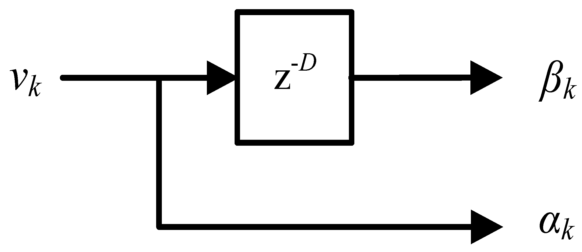
3.1. Transport Delay PLL

The transport delay (TD) is one of the most common and probably the simplest method of QSG (Figure 4). It consists of generating the quadrature signal by means of a delay D = r o u n d ( T 4 T s ) samples applied to the grid voltage, where T is the period of the fundamental grid voltage, thus, it manages to generate a periodic quadrature component by means of a memory buffer of constant length [1,35].
This QSG works properly if the voltage is a pure sinusoidal signal with constant frequency equal to the nominal of the grid, f0. Frequency variations produce a not-orthogonal quadrature signal and causes a phase error, and they reach the PD and lead to an error in the quantities detected in steady state [1].
The phase error can be partially compensated by a variable memory buffer [20]. However, this correction is not complete because the variable buffer does not consider the fractional variation of the frequency. In [36], it is recommended to consider both the integer, D = r o u n d ( π 2 ω T s ) , and fractional, T 4 T s D , parts of the delay, using the Lagrange polynomial of M order to approximate the fractional lag. The precision of this approximation depends on the order of the interpolation polynomial and the sampling frequency. When the sample rate is high, the use of a low-order interpolation polynomial is enough. However, in the case of low sampling frequencies, the use of a high-order interpolation algorithm is necessary to obtain the same level of precision, which considerably increases the computational burden of the system.
An alternative approach to that proposed is the nonfrequency-dependent TD-PLL (NTD) [37], where the QSG structure of TD is maintained, but the effect of grid frequency variations is compensated through a delay of T/4, which replaces one of the trigonometric functions in the Park transform. This modification increases memory requirements but reduces overall complexity by employing only one trigonometric function and corrects for offset errors in the TD PLL.
In [38], an adaptive TD PLL is proposed. The orthogonal version of the single-phase signal under frequency deviations can be generated as
β ( t )   = V g ( t T / 4 ) + V g ( t ) sin ( Δ ω k T / 4 ) cos ( Δ ω k T / 4 ) .
With this strategy, the orthogonal signal can be generated even in environments with frequency variations with a fixed length delay.
A different strategy is given in [39], where compensation is applied to the PLL output, by adding/subtracting a compensation phase, θ c o m p ( ω k ) , which depends on the integral action of the PI controller, Δ ω k .
θ c o m p ( ω k ) = T 8 Δ ω k

3.2. PLL Based on Inverse Park Transformation

Voltage or current representations in the stationary reference frame, i.e., αβ coordinates, can be transformed to a rotating frame of reference, dq, through the Park transformation [1]. The inverse transformation is given by
[ v α v β ] = [ cos ( γ ) sin ( γ ) sin ( γ ) cos ( γ ) ] [ v d v q ]
where γ is the angle of rotation of the axes dq referred to axes αβ.
In PLLs based on the inverse Park transformation (IPT PLL) [40], the orthogonal signal is generated by applying (3) to the output of the PD once filtered out [41,42]. Guidelines for the design and details of the IPT PLL analysis are presented in [37,43,44].
In [44,45], the PLL based on the multiharmonic decoupling cell (MHDC PLL) is proposed, where the QSG used is a combination of the TD and the IPT. With this configuration, the MHDC maintains the strength of a quadrature IPT system to attenuate the high-order harmonics at the input of the PLL, but it also inherits the delay effect of the PLL T/4, which makes it sensitive to frequency variations.

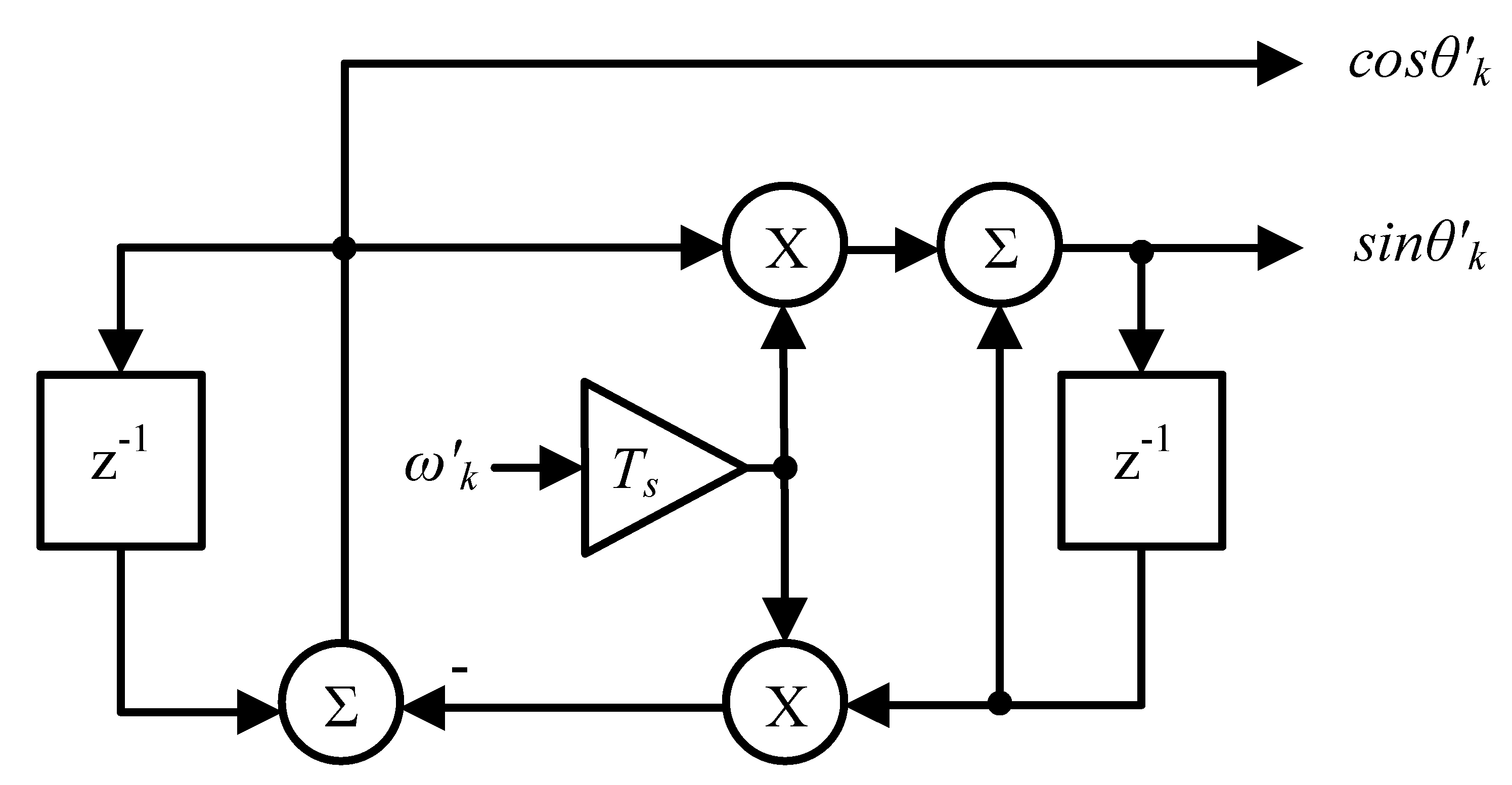
3.3. PLL Based on Synthesis Circuit

Synthesis circuit PLL (SC PLL) [46] is known as one of the simplest SRF PLLs [47]. This strategy constructs an orthogonal signal using the estimated amplitude and phase angle.
When it is necessary to extract the phase and amplitude of one or more harmonic components, or when the presence of harmonics at the input of the PLL degrades its performance, its structure can be extended to take into account the presence of harmonics [46]. In this sense, it must be considered that each additional harmonic requires an additional SC PLL, thus increasing the computational burden of the QSG.

3.4. PLL Based on Hilbert Transform

The Hilbert transform (HT) [1] is a mathematical tool that has two main characteristics. First, the phase angle of the spectral components of the input signal is shifted by ±90° as a function of its frequency, and second, it only affects the phase of the signal and has no effect on its amplitude.
The Hilbert transform of a generic signal x(t) is defined as [40]:
X ( t ) = P π x ( τ ) t τ d τ
where P indicates that the integral is a Cauchy principal value.
This technique allows the generation of an analytical signal from a real signal with unity gain, except for the DC component. The ideal Hilbert transform violates the property of causality and is therefore not feasible [41]. Because its frequency response stretches across the entire spectrum, digital realization requires an approximation. Three main approaches can be found in the literature [48,49]: complex filters, which require complex and computationally expensive hardware multipliers; the combination of two filters that form 90°, which are commonly implemented as delayed band-pass infinite impulse response (IIR) filters variables, which deteriorate PLL performance; and finite impulse response (FIR) filters, which require the real part to be delayed to adjust the relative phases of in-phase and quadrature signals. The latter approach is the preferred method for PLLs in grid-connected converters [40,41,50]. The type III and IV FIR filters can be applied as for the generation of the quadrature signal [51], but the necessary multiplications in type III are half those in type IV [49].

3.5. PLL Based on Signal Delay Compensation

Two delay buffers applied to the input voltage can be chained together (Figure 5), forming a configuration called delay signal compensation (DSC) [52] and obtaining the quadrature signal at the output of the first delay block [37,53]. Its harmonic blocking capabilities can be enhanced by adding new DSC operators before the PD and compensating for the PLL output by adding a frequency-dependent phase. Therefore, the resources required for digital implementation increase.

3.6. Derivative PLL

The PLL with generation of the quadrature signal based on a derivative block (D PLL) [54] has been widely used in the continuous domain [55]. Its digital implementation (Figure 6) produces a very precise result [56], although it requires a numerical approximation to the derived function, following one of the methods shown in Table 2, to reduce the effect of noise.
In order to reduce the noise that amplifies the calculation of the derived function, it is necessary to increase the number of samples, which, in addition, introduces a phase shift in the quadrature component. This effect can be compensated for by introducing delays in the in-phase component, while the resulting lag of the QSG must be compensated after the VCO.

3.7. PLL Based on Recursive Discrete Fourier Transform

In this technique, shown in Figure 7, the QSG uses the recursive discrete Fourier transform (RDFT) PLL [22,57]:
G R D F T ( z ) = ( 1 z D ) z 1 e j 2 π D 1 e j 2 π D z 1
where D is the number of samples considered in each period of the grid, and by assigning D = r o u n d ( 2 π   ω   T s ) , the fundamental voltage is tracked and the harmonics rejected due to the zero-pole assignment across the unit circle.
The main drawback associated with this technique is the accumulated error produced by rounding, which can lead to instabilities [58]. This drawback can be mitigated by including a damping factor in the transfer function (5):
G R D F T ( z ) = ( 1 r D z D ) r z 1 e j 2 π D 1 r e j 2 π D z 1
where r < 1 is the damping factor. From the point of view of computational burden, this approach involves many operations and largely depends on the processor or digital circuit used [58]. A fixed sampling frequency, under grid frequency variations, results in errors and oscillations in the PLL phase and a poor attenuation of harmonics in the input signal. Several solutions are possible, and the simplest is to adjust the sampling frequency according to the fundamental frequency variations so that N remains constant. However, the use of a variable sample rate may not be feasible in the application where the PLL is used. In [59], it is proposed to improve the response of the algorithm to frequency variations by redesigning it with the use of a variable sampling frequency.

3.8. PLL Based on Kalman Filtering

The real-time application of linear Kalman filters (KF) [60] estimates the state variables (xk) of a linear system by weighting the information from the system measurement equation (in the vector sk) and the previous states of the system and its inputs (xk, uk) through the filter gains, known as Kalman gains, which are also updated at each sampling interval as a function of the evolution of the estimation error. The equations of state and measure of the system are written as
{ x k + 1   =   A k x k   +   B k u k   +   Γ ξ k s k   =   C k x k   +   D k u k   +   η k
where ξ and η are noncorrelated noise sequences with normal probability distributions, Ak and Ck are the state and measurement transition matrices, respectively, and uk is a deterministic input sequence, which, in the case of application to the QSG of PLLs, can be avoided [61]. The recursive version of the Kalman filter reduces the computational load of the method, and if the model of the signals corresponds to a stochastic linear system and invariant in time, the structure of the recursive filter loop is further simplified, resulting in the so called limiting Kalman filter (LKF).
In [62], the approach used is a LKF that models the fundamental grid frequency. The recursive filter for LKF performs the estimation of the state variables and their update based on the error from the comparison of the measurement and the state estimated. A greater number of states, due to a more complex signal model, results in the use of a greater number of registers and multiplications. On the other hand, with the defined signal model, in the LKF, the values of the Kalman gains can be precalculated and stored in memory registers for use in the modified recursive loop. Therefore, the computational burden reduction in the system is significant.

3.9. PLL Based on Second-Order Generalized Integrator

The PLL based on the second-order generalized integrator (SOGI PLL) [29,35] uses an adaptive filter to improve the generation of the quadrature signal. First, the SOGI structure generates the quadrature signal of the fundamental of the grid voltage by using an integrator and, second, its structure eliminates unwanted frequency components, harmonics, from the output signals αk and βk. The block diagram of this QSG is shown in Figure 8, where the use of ω’k allows the QSG to follow the fundamental of the grid voltage.
There are many variants that can be found of this QSG in the literature. In [63,64,65], the SOGI PLL is included within an active filter structure for the generation of the quadrature signal in single-phase SRF PLLs. In [65], it is shown that the IPT and the SOGI are equivalent under certain conditions. From an implementation point of view, the SOGI proposed in [65,66,67] has a minimum resource demand applying a constant ω k = ω 0 . However, in this case, the structure is very sensitive to the frequency oscillations of the PLL due to the PD and LF used. In order to overcome these limitations, the SOGI can be combined with an FLL providing the resonant frequency and avoiding the PLL stage [1].
One drawback of this strategy is that it does not block a DC component, which give rise to errors in the output signals if they are present in the input signal. SOGI–QSG structures have been proposed in the literature that, by adding one or more zeros at the origin [67,68,69,70,71,72,73,74], prevent this effect. Attempts have also been made to improve the harmonic filtering capacity of the PLL from a closed loop feedback system [69], especially in floating arithmetic applications, with the design of a pre-filter [73] and with a structure of multiple generalized second-order integrators and an FLL [75] that reduces the computation time and obtains an algorithm with low computational burden.

3.10. PLL Based on First-Order All-Pass Filters

The first-order all-pass filter (APF) PLLs are easy to implement to create the fictitious orthogonal signal [39,76,77,78].
The first-order filter used in this method has the transfer function:
A P F ( z ) = c z 1 1 + c z 1
where c = 1 t a n ( ω k T s / 2 ) 1 + t a n ( ω k T s / 2 ) .
The use of APFs (Figure 9) to create the quadrature signal is not limited to first-order filters. In fact, higher-order APFs can also be used as in [39], where a second-order APF is proposed, although this implies an increase in computational burden.
In APFs, it is not necessary to adapt to frequency [78]. However, a compensator is often necessary at the output of the PLL to correct the phase error. In this sense, three possible topologies to generate the quadrature signal using a nonadaptive APF are discussed in [78].

3.11. PLL Based on Two-Sample
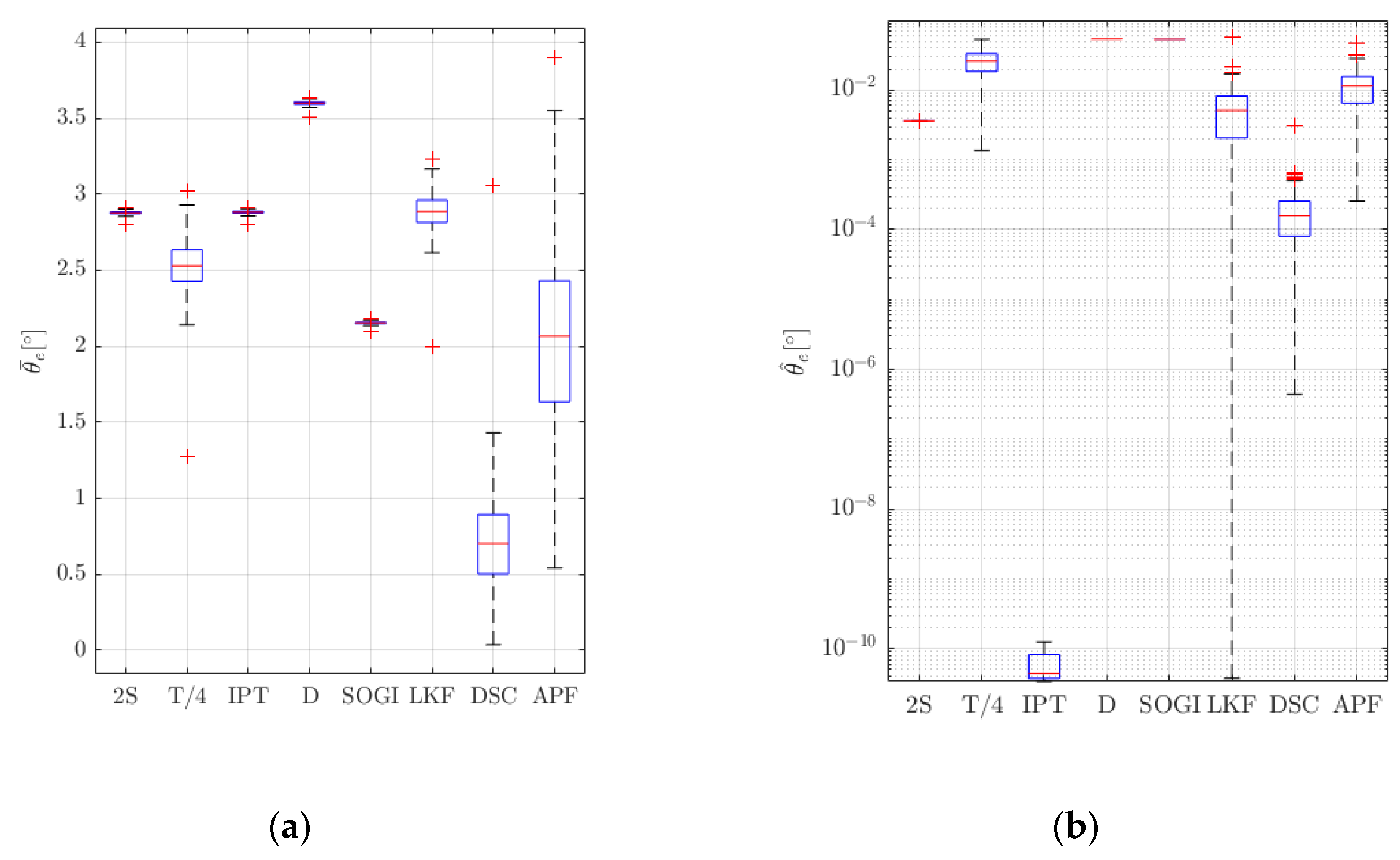
This strategy generates the quadrature signal from a buffer of two samples (2S) by applying finite differences around the operating point that can be dynamically adjusted as a function of the grid frequency ω’k, estimated by the PLL [79]. As a result, the quadrature signal at each instant k is generated with three consecutive samples of the grid voltage. Few memory resources are required. The 2S-QSG is obtained from
β k = ( α k 2 α k ) 1 s i n ( 4 π N k ) + α k t a n ( 2 π N k )
where Nk can be obtained either dynamically or taken as a fixed value.
The implementation of the 2S-QSG requires low computational burden. Furthermore, a simplification of its algorithm has been proposed, starting from the first term of the Taylor series of trigonometric functions and assuming a high sampling frequency [79], as well as the elimination of the division operation and the use of digital oscillators such as VCO [27]. A handicap of this strategy is its low immunity to noise and harmonic distortion of the voltage, which has been solved in [80], including an adaptive filter in its structure.

3.12. Evaluation

Fixed-point implementations of the QSGs versions analyzed in this section, not including complex functions such as trigonometric ones, are included in the structure of a PLL and evaluated by means of a Monte Carlo (MC) tests using MATLAB/Simulink®. These strategies are SOGI [65], DSC [37], 2S [79], T/4 [1], LKF [62], IPT [40], APF [39] and D-backward. The same PD, LF (Kp = 15.33 and Ki = 117.56) and VCO are used in all the cases, according to Figure 10. The sampling period, Ts, is 160 μs.
The MC tests consider ideal (Figure 11 and Figures 13–15) and harmonically distorted grid voltages (Figure 12) within the limits stablished in EN 50160 [81] and other effects due to the measure chain, such as noise (band-limited white noise whose noise power is 5 ppm) and DC component (2%). A total of 250 simulation conditions are generated through Latin hypercube sampling (LHS), which reduces the representative number of MC tests. Voltage harmonic combinations, with orders from 2nd to 50th and amplitudes within the individual and collective limits in EN 50160 (VTHD ≤ 8%), are considered. Results are presented according to a uniform probability density function (PDF). The nominal grid frequency changes in the test following a normal PDF, in the range from 47 up to 52 Hz.
The resulting PDFs for the measured mean phase error ( θ e ¯ ) in steady state are shown in Figure 11a. The PDFs obtained in this test for the D PLL are higher with a median equal to 3.6°. The best results are obtained with the DCS PLL with 0.7° median. The measured phase error ripple ( θ e ^ ) under the same steady state test is shown in Figure 11b, where the ripples with the D and SOGI are equivalent and with medians equal to 0.55°. Meanwhile, the IPTs present the lower results with lower errors by eight orders of magnitude. However, the strategy that performs the best during steady state, considering Figure 11, is the DSC PLL.
The resulting PDFs for the θ e ¯ in steady state under harmonic distortion is shown in Figure 12a. The PDF for the D PLL obtained in this test is again the highest, with a median 3.9° and an 8° variance. The best results are obtained with the DCS PLL with which the median is 0.7° and variance 0.4°. The measured θ e ^ under the same test is shown in Figure 12b, where the ripple with the D PLL is the worst with a median of 5.9°. Meanwhile, the APF presents the lower results with a median of 0.6°. The response time of θ e is measured from the step beginning to the time instant where θ e reaches a 3% of the peak θ e . The strategies that achieve the best response times considering both figures are DSC and APF.
The response to frequency jumps has been evaluated combining the steady-state MC conditions with different starting phases and magnitudes, in the range of 0–360° and −5–5 Hz, and assuming uniform PDFs; the results are shown in Figure 12. The lower median of the overshoot PDFs (Figure 13a) is obtained by LKF (75°), while the medians of the APF and SOGI are higher with 85° and 80°, respectively. The PDFs of the response times are shown in Figure 13b, where high-performance differences are observed. In terms of response time, the best performer is the SOGI, achieving 124 ms as median. The worst performer is the APF again (median and variance equal 140 and 7 ms, respectively).
Figure 14 shows the obtained results in the case of phase jumps. The magnitude of the jumps is uniformly distributed in the range of −90–+90°, and the starting point is applied at different phase instants in the range of 0–360°. Again, LHS is used to combine these conditions with those of the steady-state test. The PDFs of the measured overshoots and response times in the phase errors after the transient are shown in Figure 14a,b, respectively. Among all the other evaluated QSGs, the best balance of overshoot and response time is due to the SOGI (median of overshoot and response time are 45° and 128 ms, respectively), and the worst is APF (median of overshoot and response time are 46° and 147 ms, respectively).
The performance of the 2S PLLs in case of voltage dips was also analyzed. Steady-state test conditions were combined through LHS with different voltage dip depths, in the range of 20–90%, durations in the range of 10–200 ms and initial phases of 0–360°. The dynamics of the PLLs are evaluated in the falling down transient. The overshoot of the phase error is shown in Figure 15a, where the performance of the SOGI and IPT present the higher results with medians of 4.3°. Besides, the PDFs of the measured response times are shown in Figure 15b, and the largest median corresponds to SOGI (119 ms). However, the best performance under voltage dips in general terms is obtained by the D PLL.
For comparison purposes, Table 3 summarizes the number of operations and memory units required for the digital implementation of the equivalent blocks of QSG in single-phase PLLs, described in Section 2 and Section 3. Initially, the originally proposed structures (such as SOGI [65], T/4 [1], DSC [37] or D-Backward) are simple. However, the successive proposals presented in the literature to improve its behavior under grid disturbances increase its computational burden and the complexity of the circuit (for example, in the case of multiSOGI structure (MSOGI) [75], T/4 [39], DSC + filter [53] or D-Richardson). On the other hand, the memory registers depend on the sampling frequency used in the circuit (such as the proposals based on T/4) or the number of blocks implemented to eliminate harmonics from the grid voltage (like 2S + filter [80] or the MSOGI [75]). This is why the designer must balance the need to comply with the computational burden and timing requirements in its system and the behavior of the strategy under grid disturbances that is required.
The synthesis of PLLs in an FPGA can be carried out through different methods. Designers have specific rapid prototyping programs available, such as SysGen of Xilinx, or high-level codes, e.g., C language, which implement the circuit using nonoptimized preconfigured blocks. Other methods, intended to reduce the computational resources used in the FPGA from the point of view of the number of hardware resources required and/or the area occupied by the circuit, are available, such as the use of pre-configured Xilinx blocks (intellectual property, IP) or the design of reconfigurable modules based on an adder/subtractor.
IPs can be configured depending on the elements that compose them, specifying whether their implementation is carried out through DSP or LUTs. The choice of the synthesis procedure depends on the needs of the designer and the free resources in the FPGA to embed the algorithm. This type of circuit uses a control block that defines the finite state machine (FSM) of the proposed PLL and the IP blocks that it calls in parallel depending on the needs of the algorithm in each state or clock cycle. In contrast, in those cases where the requirements of the control of the power converter assume that the sample rate of the synchronization circuit outputs is much lower than the clock frequency of the digital device used in the control, it is possible to design a circuit that further reduces the hardware resources required in the FPGA with respect to the previous proposal, increasing the execution time of the algorithm. Here, the Booth-type reconfigurable modules based on an adder/subtractor block reduce both the area occupied and the number of hardware resources.
Following the rapid prototyping technique with SysGen, Table 4 shows a comparison with the resources consumed by each PLL analyzed in relation to the computational burden obtained by the five of the simplest strategies in Table 3. In order to facilitate its understanding, the resources of each strategy are compared in percentage terms with the resources obtained in the implementation of the T/4 PLL, as this is the PLL based on the Park transform, which is easier to implement and widely consolidated in the literature. Table 4 shows that, although the five strategies show similar resource consumption, the 2S and the DSC PLL are the two strategies that require less resources after the T/4 PLL. The structure of Figure 10 is a traditional and nonoptimized implementation of PLLs, so the use of different QSGs does not significantly affect the computational burden of the circuit. To appreciate a greater difference, it is necessary to use more optimized implementations such as that presented in Figure 16. This last PLL implementation scheme presents three optimizations that significantly reduce the computational burden using an oscillator, which replaces trigonometric functions, and eliminating the division operation and the normalization block, assuming high switching frequency [79].
On the other hand, as an example of the application of the different implementation techniques, Table 5 compares the hardware resources consumed by the optimized 2S PLL [79] and the cycles necessary to develop the circuit, according to Figure 16. The proposed strategy (using SysGen) assumes a 93.2% reduction in the slice register and 75.1%, 74.0% and 78.4% of LUTs, occupied sections and LUT flip-flop pairs, respectively. In contrast, the reduction of DSPs is 61.1% compared to the circuit of Figure 10. Moreover, if the implementation techniques are compared, Table 5 shows that rapid prototyping presents nonoptimized algorithms that abuse the use of DSPs compared to the use of specific hardware techniques.

4. Conclusions

To achieve a good current reference for grid connected converters, even in weak grids, the design of the functional blocks in the PLL must take a compromise solution between the quality of the dynamic and steady-state response and the computational burden. Steady-state results show that the consistency of the D-backward and 2S PLLs deteriorates the most due to the harmonic distortion, from variance 3.58° to 3.61° and 2.87° to 2.89°, respectively. All the QSGs perform worst in terms of phase ripple by increasing the harmonic distortion, from the 5.37 × 10²°–5.38 × 10²° range to 3.58 × 10³°–3.6 × 10³° respectively. In frequency and phase jumps tests, the PLLs resulting in shorter response times are SOGI, IPT, 2S and D PLLs, with similar consistency (e.g., the variance) across the MC tests. Voltage dips tests show that 2S and D PLLs are the best performers, both in terms of maximum phase error (with medium of 0.7° and 0.38° in the range of 0.55°–0.77° and 0.32°–0.42°, respectively) and response times (with medium of 131 and 138 ms in the range of 65–158 ms and 92–148 ms, respectively). The number of operations and memory units required by each analyzed PLL shows that the QSGs resulting in less resources are SOGI, 2S and D ones. It is also shown that by adapting this QSGs to filter out harmonics, the computational burden increases (see Table 3). A selection of these QSGs has been also implemented by means of an automatic tool, e.g., SysGen, in a field programmable gate array (see Table 5), showing that the 2S PLL uses a similar amount of registers than the T/4 PLL (+0.4%) while other QSGs require +1.41% (DSC PLL) or more +8.12% (Hilbert PLL). In terms of LUTs and occupied sections, the DSC PLL performs the best with this automated generation tool. In order to evaluate the performance of these automated tools for rapid prototyping, the 2S PLL has been also implemented by means of specific hardware, and it is demonstrated (see Table 4) that the number of LUTs, occupied sections and flip flops required can be reduced significatively. Hence, from the analysis carried out, the most suitable QSG for a specific application where a cost-effective solution is required, should consider the both the PLL performance under diverse operation conditions and the associated computational burden.

Author Contributions

P.L., A.P. and F.J.A. proposed the main idea of the paper; the paper was written by P.L. and A.P., and was revised by F.J.A. All the authors were involved in preparing the final version of this manuscript. All authors have read and agreed to the published version of the manuscript.

Funding

This work has been supported by the Spanish Ministry of Science and Innovation under Project RTI2018-095138-B-C31 PEGIA—Power Electronics for the Grid and Industry Applications.

Conflicts of Interest

The authors declare no conflict of interest.

Abbreviations

APF PLLPLL based on first-order all-pass filters
CORDICCoordinate Rotation Digital Computer
DDerivative
DCDirect current
DCODigitally Controlled Oscillator
DSODistribution system operators
DSCDelay Signal Compensation
DSPDigital signal processor
D PLLPLL based on derivative
EPLLEnhanced Phase-Locked Loop
FIRFinite Impulse Response
FPGAField Programmable Gate Array
FSMFinite state machine
HTHilbert transform
IIRInfinite Impulse Response
IPIntellectual Property
IPT PLLPhase-Locked Loop based on the inverse of Park transformation
KFKalman filter
LFLoop filter
LHSLatin Hypercube Sampling
LKFLimiting Kalman filter
LUTLook Up Tables
LVLow-voltage
MCMonte Carlo
MHDC PLLPhase-locked loop based on multiharmonic decoupling cell
MSOGIMultisecond-order generalized integrator
NTDNonfrequency-dependent TD
PDPhase detector
PDFProbability density function
PIProportional–integral
PLLPhase-locked loop
pPLLPower-based phase-locked loop
SC PLLSynthesis circuit phase-locked loop
SOGI PLLPLL based on the second-order generalized integrator
QSGQuadrature signal generation
QSG PLLPLLs based on the quadrature signal generation
RDFT PLLPLL based on recursive discrete Fourier transform
SRF PLLSynchronous reference frame phase-locked loop
TD PLLTransport delay phase-locked loop
VCOVoltage controlled oscillator
2S-QSGQuadrature signal generation based on two samples

References

  1. Teodorescu, R.; Liserre, M.; Rodriguez, P. Grid Converters for Photovoltaic and Wind Power Systems; John Wiley & Sons: Hoboken, NJ, USA, 2011; Volume 29. [Google Scholar]
  2. Peña Asensio, A.; Gonzalez-Longatt, F.; Arnaltes, S.; Rodríguez-Amenedo, J.L. Analysis of the Converter Synchronizing Method for the Contribution of Battery Energy Storage Systems to Inertia Emulation. Energies 2020, 13, 1478. [Google Scholar] [CrossRef] [Green Version]
  3. Zhu, R.; Liserre, M. Control of Smart Transformer Under Single-Phase to Ground Fault Condition. IEEE Trans. Power Electron. 2020, 35, 2034–2043. [Google Scholar] [CrossRef]
  4. Liu, S.-M.; Tu, C.-H.; Lin, C.-L.; Liu, V.-T. Field-Oriented Driving/Braking Control for Electric Vehicles. Electronics 2020, 9, 1484. [Google Scholar] [CrossRef]
  5. Ku, B.; Liu, J. Converter-Switching Surges: Railroad Vehicle Power Converter Impact Studies. IEEE Veh. Technol. Mag. 2012, 7, 57–66. [Google Scholar] [CrossRef]
  6. Hazell, P.; Mather, P.; Longstaff, A.; Fletcher, S. Digital System Performance Enhancement of a Tent Map-Based ADC for Monitoring Photovoltaic Systems. Electronics 2020, 9, 1554. [Google Scholar] [CrossRef]
  7. Cho, S.-M.; Kim, J.-C.; Yun, S.-Y. Optimum State-of-Charge Operating Range for Frequency Regulation of Energy Storage Systems Using a Master–Slave Parallel Genetic Algorithm. Electronics 2020, 9, 1298. [Google Scholar] [CrossRef]
  8. Ashabani, M.; Freijedo, F.D.; Golestan, S.; Guerrero, J.M. Inducverters: PLL-Less Converters with Auto-Synchronization and Emulated Inertia Capability. IEEE Trans. Smart Grid 2016, 7, 1660–1674. [Google Scholar] [CrossRef]
  9. Yu, B. An Improved Frequency Measurement Method from the Digital PLL Structure for Single-Phase Grid-Connected PV Applications. Electronics 2018, 7, 150. [Google Scholar] [CrossRef] [Green Version]
  10. Zeb, K.; Islam, S.U.; Din, W.U.; Khan, I.; Ishfaq, M.; Busarello, T.D.C.; Ahmad, I.; Kim, H.J. Design of Fuzzy-PI and Fuzzy-Sliding Mode Controllers for Single-Phase Two-Stages Grid-Connected Transformerless Photovoltaic Inverter. Electronics 2019, 8, 520. [Google Scholar] [CrossRef] [Green Version]
  11. Lo, Y.; Lee, T.; Wu, K. Grid-Connected Photovoltaic System with Power Factor Correction. IEEE Trans. Ind. Electron. 2008, 55, 2224–2227. [Google Scholar] [CrossRef]
  12. Choudhury, A.R.; Pati, S.; Choudhury, A.; Mohanty, K.B. Control of voltage & frequency of a hybrid microgrid using a FLC based bidirectional converter equipped with BESS. In Proceedings of the 2018 Technologies for Smart-City Energy Security and Power (ICSESP), Bhubaneswar, India, 28–30 March 2018; pp. 1–6. [Google Scholar]
  13. Faisal, M.; Hannan, M.A.; Ker, P.J.; Rahman, M.S.B.A.; Mollik, M.S.; Mansur, M.B. Review of Solid State Transfer Switch on Requirements, Standards, Topologies, Control, and Switching Mechanisms: Issues and Challenges. Electronics 2020, 9, 1396. [Google Scholar] [CrossRef]
  14. Best, R.E. Simulation and Applications. In Phase-Locked Loops. Design, 4th ed.; McGraw Hill Professional: New York, NY, USA, 1999. [Google Scholar]
  15. Gardner, F.M. Phaselock Techniques; John Wiley and Sons Ltd: Hoboken, NJ, USA, 2005. [Google Scholar]
  16. Golestan, S. Modeling, Analyzing, and Designing Advanced Synchronization Techniques for Power Converters; Aalborg University: Aalborg, Denmark, 2018. [Google Scholar]
  17. Karimi-Ghartema, M. Enhanced Phase-Locked Loop Structures for Power and Energy Applications, 1st ed.; IEEE Press Series on Microelec: Hoboken, NJ, USA, 2014; ISBN 978-1-118-79502-6. [Google Scholar]
  18. Golestan, S.; Monfared, M.; Freijedo, F.D.; Guerrero, J.M. Advantages and Challenges of a Type-3 PLL. IEEE Trans. Power Electron. 2013, 28, 4985–4997. [Google Scholar] [CrossRef] [Green Version]
  19. Liu, H.; Wu, Z. Demodulation of Angular Position and Velocity from Resolver Signals via Chebyshev Filter-Based Type III Phase Locked Loop. Electronics 2018, 7, 354. [Google Scholar] [CrossRef] [Green Version]
  20. Yang, Y.; Zhou, K.; Blaabjerg, F. Exploitation of digital filters to advance the single-phase T/4 delay PLL system. In Proceedings of the 2016 IEEE 2nd Annual Southern Power Electronics Conference (SPEC), Auckland, New Zealand, 5–8 December 2016; pp. 1–6. [Google Scholar]
  21. Gonzalez-Espin, F.; Figueres, E.; Garcera, G. An Adaptive Synchronous-Reference-Frame Phase-Locked Loop for Power Quality Improvement in a Polluted Utility Grid. IEEE Trans. Ind. Electron. 2012, 59, 2718–2731. [Google Scholar] [CrossRef] [Green Version]
  22. Sumathi, P.; Janakiraman, P.A. Phase locking scheme based on look-up-table-assisted sliding discrete fourier transform for low-frequency power and acoustic signals. IET Circuits Devices Syst. 2011, 5, 494–504. [Google Scholar] [CrossRef]
  23. Meyer-Baese, U. Signals and Communication Technology. In Digital Signal Processing with Field Programmable Gate Arrays, 3rd ed.; Springer: Berlin/Heidelberg, Germany, 2007; ISBN 978-3-540-72613-5. [Google Scholar]
  24. Panda, S.R.; Babu, B.C. Phase estimation for grid synchronization using CORDIC algorithm with SRF-PLL. In Proceedings of the 2012 IEEE Students’ Conference on Electrical, Electronics and Computer Science, Bhopal, India, 1–2 March 2012; pp. 1–4. [Google Scholar]
  25. Huimei, Y.; Hao, S.; Yu, S. Optimized Design and Implementation of Three-Phase PLL Based on FPGA. In Proceedings of the 2009 International Conference on Computer Engineering and Technology, Singapore, 22–24 January 2009; Volume 1, pp. 129–133. [Google Scholar]
  26. Freijedo, F.D.; Doval-Gandoy, J.; Lopez, O.; Cabaleiro, J. Robust phase locked loops optimized for DSP implementation in power quality applications. In Proceedings of the 2008 34th Annual Conference of IEEE Industrial Electronics, Orlando, FL, USA, 10–13 November 2008; pp. 3052–3057. [Google Scholar]
  27. Lamo, P.; Pigazo, A.; Ruiz, G.A.; Azcondo, F.J.; López, F. An Optimized Implementation of a Two-Sample Phase Locked Loop with Frequency Feedback for Single-Phase Sensorless Bridgeless PFC. In Proceedings of the 2018 IEEE 19th Workshop on Control and Modeling for Power Electronics (COMPEL), Padua, Italy, 25–28 June 2018; pp. 1–6. [Google Scholar]
  28. Masoud, K.G. Linear and Pseudolinear Enhanced Phased-Locked Loop (EPLL) Structures. IEEE Trans. Ind. Electron. 2014, 61, 1464–1474. [Google Scholar]
  29. Ghartemani, M.K.; Khajehoddin, S.A.; Jain, P.K.; Bakhshai, A. Problems of Startup and Phase Jumps in PLL Systems. IEEE Trans. Power Electron. 2012, 27, 1830–1838. [Google Scholar] [CrossRef]
  30. Khadkikar, V.; Chandra, A.; Singh, B.N. Generalised single-phase p-q theory for active power filtering: Simulation and DSP-based experimental investigation. IET Power Electron. 2009, 2, 67–78. [Google Scholar] [CrossRef] [Green Version]
  31. Correa, J.M.; Farret, F.A.; Simoes, M.G. Application of a Modified Single-Phase P-Q Theory in the Control of Shunt and Series Active Filters in a 400 Hz Microgrid. In Proceedings of the 2005 IEEE 36th Power Electronics Specialists Conference, Recife, Brazil, 16 June 2005; pp. 2585–2591. [Google Scholar]
  32. Yang, Y.; Blaabjerg, F. Synchronization in single-phase grid-connected photovoltaic systems under grid faults. In Proceedings of the 2012 3rd IEEE International Symposium on Power Electronics for Distributed Generation Systems (PEDG), Aalborg, Denmark, 25–28 June 2012; pp. 476–482. [Google Scholar]
  33. Liu, J.; Yang, J.; Wang, Z. A new approach for single-phase harmonic current detecting and its application in a hybrid active power filter. In Proceedings of the 25th Annual Conference of the IEEE Industrial Electronics Society, 1999. IECON ’99 Proceedings, San Jose, CA, USA, 29 November–3 December 1999; Volume 2, pp. 849–854. [Google Scholar]
  34. Haque, M.T. Single-phase pq theory for active filters. In Proceedings of the TENCON ’02. Proceedings, 2002 IEEE Region 10 Conference on Computers, Communications, Control and Power Engineering, Beijing, China, 28–31 October 2002; Volume 3, pp. 1941–1944. [Google Scholar]
  35. Gupta, A.; Porippireddi, A.; Srinivasa, V.U.; Sharma, A.; Kadam, M. Comparative study of single phase PLL algorithms for grid synchronization applications. IJECT 2012, 3, 237–245. [Google Scholar]
  36. Hadjidemetriou, L.; Yang, Y.; Kyriakides, E.; Blaabjerg, F. A Synchronization Scheme for Single-Phase Grid-Tied Inverters under Harmonic Distortion and Grid Disturbances. IEEE Trans. Power Electron. 2016. [Google Scholar] [CrossRef]
  37. Golestan, S.; Guerrero, J.M.; Vidal, A.; Yepes, A.G.; Doval-Gandoy, J.; Freijedo, F.D. Small-Signal Modeling, Stability Analysis and Design Optimization of Single-Phase Delay-Based PLLs. IEEE Trans. Power Electron. 2016, 31, 3517–3527. [Google Scholar] [CrossRef] [Green Version]
  38. Golestan, S.; Guerrero, J.; Abusorrah, A.; Al-Hindawi, M.; Al-Turki, Y. An Adaptive Quadrature Signal Generation-Based Single-Phase Phase-Locked Loop for Grid-Connected Applications. IEEE Trans. Ind. Electron. 2016. [Google Scholar] [CrossRef]
  39. Choi, J.W.; Kim, Y.K.; Kim, H.G. Digital PLL control for single-phase photovoltaic system. IEE Proc. Electr. Power Appl. 2006, 153, 40–46. [Google Scholar] [CrossRef]
  40. Nicastri, A.; Nagliero, A. Comparison and evaluation of the PLL techniques for the design of the grid-connected inverter systems. In Proceedings of the 2010 IEEE International Symposium on Industrial Electronics, Bari, Italy, 4–7 July 2010; pp. 3865–3870. [Google Scholar]
  41. Silva, S.M.; Lopes, B.M.; Filho, B.J.C.; Campana, R.P.; Bosventura, W.C. Performance evaluation of PLL algorithms for single-phase grid-connected systems. In Proceedings of the Conference Record of the 2004 IEEE Industry Applications Conference, 39th IAS Annual Meeting, Seattle, WA, USA, 3–7 October 2004; Volume 4, pp. 2259–2263. [Google Scholar]
  42. Han, Y.; Luo, M.; Zhao, X.; Guerrero, J.M.; Xu, L. Comparative Performance Evaluation of Orthogonal-Signal-Generators-Based Single-Phase PLL Algorithms—A Survey. IEEE Trans. Power Electron. 2016, 31, 3932–3944. [Google Scholar] [CrossRef] [Green Version]
  43. Filho, R.M.S.; Seixas, P.F.; Cortizo, P.C.; Torres, L.A.B.; Souza, A.F. Comparison of Three Single-Phase PLL Algorithms for UPS Applications. IEEE Trans. Ind. Electron. 2008, 55, 2923–2932. [Google Scholar] [CrossRef]
  44. Hadjidemetriou, L.; Kyriakides, E.; Yang, Y.; Blaabjerg, F. Power quality improvement of single-phase photovoltaic systems through a robust synchronization method. In Proceedings of the 2014 IEEE Energy Conversion Congress and Exposition (ECCE), Pittsburgh, PA, USA, 14–18 September 2014; pp. 2625–2632. [Google Scholar]
  45. Hadjidemetriou, L.; Kyriakides, E.; Yang, Y.; Blaabjerg, F. A Synchronization Method for Single-Phase Grid-Tied Inverters. IEEE Trans. Power Electron. 2016, 31, 2139–2149. [Google Scholar] [CrossRef]
  46. Fang, X.; Wang, Y.; Li, M.; Liu, J. A novel frequency-adaptive PLL for single-phase grid-connected converters. In Proceedings of the 2010 IEEE Energy Conversion Congress and Exposition, Atlanta, GA, USA, 12–16 September 2010; pp. 414–419. [Google Scholar]
  47. Karimi-Ghartemani, M. A Unifying Approach to Single-Phase Synchronous Reference Frame PLLs. IEEE Trans. Power Electron. 2013, 28, 4550–4556. [Google Scholar] [CrossRef]
  48. Kumm, M.; Sanjari, M.S. Digital hilbert transformers for FPGA-based phase-locked loops. In Proceedings of the 2008 International Conference on Field Programmable Logic and Applications, Heidelberg, Germany, 8–10 September 2008; pp. 251–256. [Google Scholar]
  49. Komodromos, M.Z.; Russell, S.F.; Tang, P.T.P. Design of FIR Hilbert transformers and differentiators in the complex domain. IEEE Trans. Circuits Syst. Fundam. Theory Appl. 1998, 45, 64–67. [Google Scholar] [CrossRef]
  50. Giampaolo, B.; Barater, D.; Tarisciotti, L.; Zanchetta, P. High-dynamic single-phase Hilbert-based PLL for improved phase-jump ride-through in grid-connected inverters. In Proceedings of the 2014 IEEE Energy Conversion Congress and Exposition (ECCE), Pittsburgh, PA, USA, 14–18 September 2014; pp. 4932–4939. [Google Scholar]
  51. Ingle, V.K.; Proakis, J.G. Digital Signal Processing Using MATLAB, 3rd ed.; CL Engineering: Stamford, CT, USA, 2011; ISBN 978-1-111-42737-5. [Google Scholar]
  52. Kaiser, J.; Hamming, R. Sharpening the response of a symmetric nonrecursive filter by multiple use of the same filter. In Proceedings of the Acoustics, Speech, and Signal Processing, IEEE International Conference on ICASSP ’77, Hartford, CT, USA, 9–11 May 1977; Volume 2, pp. 82–85. [Google Scholar]
  53. Golestan, S.; Freijedo, F.D.; Vidal, A.; Yepes, A.G.; Guerrero, J.M.; Doval-Gandoy, J. An Efficient Implementation of Generalized Delayed Signal Cancellation PLL. IEEE Trans. Power Electron. 2016, 31, 1085–1094. [Google Scholar] [CrossRef] [Green Version]
  54. Galkin, I.; Vorobyov, M. Optimizing of sampling in a low-cost single-phase instantaneous AC-grid synchronization unit with discrete calculation of derivative function. In Proceedings of the IECON 2015—41st Annual Conference of the IEEE Industrial Electronics Society, Yokohama, Japan, 9–12 November 2015; pp. 004538–004543. [Google Scholar]
  55. Picardi, C.; Sgrò, D.; Gioffré, G. A simple and low-cost PLL structure for single-phase grid-connected inverters. In Proceedings of the SPEEDAM 2010, Pisa, Italy, 14–16 June 2010; pp. 358–362. [Google Scholar]
  56. Galkin, I.; Vorobyov, M. Implementation of single-phase grid synchronization module with low-end microcontrollers. In Proceedings of the 2014 55th International Scientific Conference on Power and Electrical Engineering of Riga Technical University (RTUCON), Riga, Latvia, 14 October 2014; pp. 84–87. [Google Scholar]
  57. Subramanian, C.; Kanagaraj, R. Single-Phase Grid Voltage Attributes Tracking for the Control of Grid Power Converters. IEEE J. Emerg. Sel. Top. Power Electron. 2014, 2, 1041–1048. [Google Scholar] [CrossRef]
  58. Darwish, H.A.; Fikri, M. Practical Considerations for Recursive DFT Implementation in Numerical Relays. IEEE Trans. Power Deliv. 2007, 22, 42–49. [Google Scholar] [CrossRef]
  59. McGrath, B.P.; Holmes, D.G.; Galloway, J.J.H. Power converter line synchronization using a discrete Fourier transform (DFT) based on a variable sample rate. IEEE Trans. Power Electron. 2005, 20, 877–884. [Google Scholar] [CrossRef]
  60. Chui, C.K.; Chen, G. Kalman Filtering with Real Time Applications, 4th ed.; Springer: New York, NY, USA, 2009. [Google Scholar]
  61. Girgis, A.A.; Chang, W.B.; Makram, E.B. A digital recursive measurement scheme for online tracking of power system harmonics. IEEE Trans. Power Deliv. 1991, 6, 1153–1160. [Google Scholar] [CrossRef]
  62. Brabandere, K.D.; Loix, T.; Engelen, K.; Bolsens, B.; den Keybus, J.V.; Driesen, J.; Belmans, R. Design and Operation of a Phase-Locked Loop with Kalman Estimator-Based Filter for Single-Phase Applications. In Proceedings of the IECON 2006—32nd Annual Conference on IEEE Industrial Electronics, Paris, France, 6–10 November 2006; pp. 525–530. [Google Scholar]
  63. Rodriguez, P.; Teodorescu, R.; Candela, I.; Timbus, A.V.; Liserre, M.; Blaabjerg, F. New Positive-sequence Voltage Detector for Grid Synchronization of Power Converters under Faulty Grid Conditions. In Proceedings of the 2006 37th IEEE Power Electronics Specialists Conference, Jeju, Korea, 18–22 June 2006; pp. 1–7. [Google Scholar]
  64. Ciobotaru, M.; Teodorescu, R.; Blaabjerg, F. A New Single-Phase PLL Structure Based on Second Order Generalized Integrator. In Proceedings of the 37th IEEE Power Electronics Specialists Conference (PESC ’06), Jeju, Korea, 18–22 June 2006; pp. 1–6. [Google Scholar]
  65. Golestan, S.; Monfared, M.; Freijedo, F.D.; Guerrero, J.M. Dynamics Assessment of Advanced Single-Phase PLL Structures. IEEE Trans. Ind. Electron. 2013, 60, 2167–2177. [Google Scholar] [CrossRef]
  66. Monter, A.R. Contributions to Cascade Linear Control Strategies Applied to Grid-Connected Voltage-Source Converters. Ph.D. Thesis, Universidad de Alcalá de Henares, Alcalá de Henares, Spain, 2013. [Google Scholar]
  67. Ciobotaru, M.; Teodorescu, R.; Agelidis, V.G. Offset rejection for PLL based synchronization in grid-connected converters. In Proceedings of the 2008 Twenty-Third Annual IEEE Applied Power Electronics Conference and Exposition, Austin, TX, USA, 24–28 February 2008; pp. 1611–1617. [Google Scholar]
  68. Shinnaka, S. A Robust Single-Phase PLL System with Stable and Fast Tracking. IEEE Trans. Ind. Appl. 2008, 44, 624–633. [Google Scholar] [CrossRef]
  69. Trento, B.; Wang, B.; Sun, K.; Tolbert, L.M. Integration of phase-locked loop based real-time oscillation tracking in grid synchronized systems. In Proceedings of the 2014 IEEE PES General Meeting Conference Exposition, National Harbor, MD, USA, 27–31 July 2014; pp. 1–5. [Google Scholar]
  70. Karimi-Ghartemani, M.; Khajehoddin, S.A.; Jain, P.K.; Bakhshai, A.; Mojiri, M. Addressing DC Component in PLL and Notch Filter Algorithms. IEEE Trans. Power Electron. 2012, 27, 78–86. [Google Scholar] [CrossRef]
  71. Fedele, G.; Ferrise, A.; Muraca, P. An adaptive quasi-notch filter for a biased sinusoidal signal estimation. In Proceedings of the 2011 9th IEEE International Conference on Control and Automation (ICCA), Santiago, Chile, 19–21 December 2011; pp. 1060–1065. [Google Scholar]
  72. Fedele, G.; Ferrise, A. Non Adaptive Second-Order Generalized Integrator for Identification of a Biased Sinusoidal Signal. IEEE Trans. Autom. Control 2012, 57, 1838–1842. [Google Scholar] [CrossRef]
  73. Matas, J.; Castilla, M.; Miret, J.; de Vicuña, L.G.; Guzman, R. An Adaptive Prefiltering Method to Improve the Speed/Accuracy Tradeoff of Voltage Sequence Detection Methods Under Adverse Grid Conditions. IEEE Trans. Ind. Electron. 2014, 61, 2139–2151. [Google Scholar] [CrossRef]
  74. Xin, Z.; Wang, X.; Qin, Z.; Lu, M.; Loh, P.C.; Blaabjerg, F. An Improved Second-Order Generalized Integrator Based Quadrature Signal Generator. IEEE Trans. Power Electron. 2016, 31, 8068–8073. [Google Scholar] [CrossRef]
  75. Rodriguez, P.; Luna, A.; Candela, I.; Mujal, R.; Teodorescu, R.; Blaabjerg, F. Multiresonant Frequency-Locked Loop for Grid Synchronization of Power Converters Under Distorted Grid Conditions. IEEE Trans. Ind. Electron. 2011, 58, 127–138. [Google Scholar] [CrossRef] [Green Version]
  76. Thacker, T.; Wang, R.; Dong, D.; Burgos, R.; Wang, F.; Boroyevich, D. Phase-Locked Loops using State Variable Feedback for Single-Phase Converter Systems. In Proceedings of the 2009 Twenty-Fourth Annual IEEE Applied Power Electronics Conference and Exposition, Washington, DC, USA, 15–19 February 2009; pp. 864–870. [Google Scholar]
  77. Blanco, C.; Reigosa, D.; Briz, F.; Guerrero, J.M. Quadrature signal generator based on all-pass filter for single-phase synchronization. In Proceedings of the 2014 IEEE Energy Conversion Congress and Exposition (ECCE), Pittsburgh, PA, USA, 14–18 September 2014; pp. 2655–2662. [Google Scholar]
  78. Ramezani, M.; Golestan, S.; Li, S. Non-frequency sensitive all-pass filter based single-phase PLLs. In Proceedings of the 2016 IEEE/PES Transmission and Distribution Conference and Exposition (T D), Dallas, TX, USA, 3–5 May 2016; pp. 1–5. [Google Scholar]
  79. Lamo, P.; López, F.; Pigazo, A.; Azcondo, F.J. An Efficient FPGA Implementation of a Quadrature Signal-Generation Subsystem in SRF PLLs in Single-Phase PFCs. IEEE Trans. Power Electron. 2017, 32, 3959–3969. [Google Scholar] [CrossRef]
  80. Lamo, P.; Pigazo, A.; Azcondo, F.J. Two-Sample PLL with Harmonic Filtering Capability Applicable to Single-Phase Grid-Connected Converters. IEEE J. Emerg. Sel. Top. Power Electron. 2020. [Google Scholar] [CrossRef]
  81. De Normalización, A.E. UNE-EN 50160: Voltage Characteristics of Electricity Supplied by Public Electricity Networks. Available online: https://www.une.org/encuentra-tu-norma/busca-tu-norma/norma?c=N0055031 (accessed on 1 October 2020).
Figure 1. Basic structure of a phase-locked loop (PLL).
Electronics 09 02026 g001
Figure 2. Implementation of the digitally controlled oscillator (DCO) proposed in [27].
Electronics 09 02026 g002
Figure 3. General structure of a single-phase synchronous reference frame (SRF) PLL.
Electronics 09 02026 g003
Figure 4. Discrete time representation of the QSG of the transport delay (TD) PLL.
Electronics 09 02026 g004
Figure 5. QSG with two delay buffers.
Electronics 09 02026 g005
Figure 6. QSG of the derivative PLL.
Electronics 09 02026 g006
Figure 7. Quadrature signal generator with recursive discrete Fourier transform (RDFT) where a = cos ( 2 π / N ) and b = sin ( 2 π / N ) .
Electronics 09 02026 g007
Figure 8. Block diagram of the QSG second-order generalized integrator (SOGI).
Electronics 09 02026 g008
Figure 9. Diagram of the first-order APF PLL.
Electronics 09 02026 g009
Figure 10. Structure of the PLL used in the tests.
Electronics 09 02026 g010
Figure 11. Results of Monte Carlo (MC) tests in steady state. Grid voltage and the nominal grid frequency are combined through Latin hypercube sampling (LHS). (a) Mean phase error and (b) Ripple of the phase error.
Electronics 09 02026 g011
Figure 12. Results of MC tests in steady state. Harmonic distortion of the grid voltage and the nominal grid frequency are combined through LHS. (a) Mean phase error and (b) Ripple of the phase error.
Electronics 09 02026 g012
Figure 13. Results of MC tests with frequency jumps. Starting phase angle and jump magnitude are varied through LHS. (a) Overshoot of the phase errors and (b) response times.
Electronics 09 02026 g013
Figure 14. Results of MC tests with phase jumps. Starting phase angle and jump magnitude are varied through LHS. (a) Overshoot of the peak phase error and (b) response times.
Electronics 09 02026 g014
Figure 15. Results of MC tests with voltage dips. Starting phase angle, dip depth and duration are varied through LHS. (a) Overshoot of the peak phase error and (b) response times.
Electronics 09 02026 g015
Figure 16. Structure of the optimized 2S-PLL [79] used in the Table 5.
Electronics 09 02026 g016
Table 1. Summary of building blocks of the PLLs.
Functional BlocksTypeComputational BurdenDynamics
PDEPLL [29,30]MediumPerformance issues due to the π/2 phase shift
pPLL [31,32]MediumOscillations of the phase error signal
QSG PLLDepend on the selected strategy
(see next section)
LFZero order [17]LowPerformance issues under phase ramps and frequency variations
First order [1]LowGood under slow variations in the grid frequency
High order [19,20]Medium–HighGood
Adaptive [21,22]HighGood
VCOLUTs [22]HighGood
CORDIC [24,25]HighGood
DCO [26]LowGood
Table 2. Approaches to the derived function.
Approach α β = x ( t ) ω
D-backward x ( t ) 1 ω x ( t ) x ( t T s ) T s
D-central difference x ( t T s ) 1 ω x ( t + T s ) x ( t T s ) 2 T s
D-Richardson extrapolation x ( t 2 T s ) 1 ω x ( t + 2 T s ) + 8 x ( t + T s ) 8 x ( t T s ) + x ( t 2 T s ) 12 T s
Table 3. Number of operations and memory units required for the digital implementation.
QSG+/−×/÷TM
SOGI [65]4302
MSOGI [75]1 + 6F4F02F
DSC [37]1102 × round(N/4)
DSC + filter [53]1023616 × round(N)
2S [79]2302
2S + filter [80]3 + 3F3 + 4F02 + 3F
T/4 [1]000round(N/4)
Recent T/4 [39]110round(N/4)
KF [60]40734960
LKF [62]81300
IPT [40]6706
MHDC [44,45]91229
SC [46]2311
HT [1]53010
APF [39,76]2202
D-backward1101
D-central difference1105
D-Richardson extrapolation32014
RDFT [22]450N + 3
pq theory [31]3411
Enhanced [28]2521
×/÷ = gains, multiplications and divisions, T = trigonometric functions, M = data memory units, F = number of harmonic orders considered and N = 2π/(ω’kTs).
Table 4. Summary of resources consumed by different PLLs in the field-programmable gate array (FPGA) using SysGen.
T/42SDSCHilbertSOGI
UnitsUnits%Units%Units%Units%
Registers34723486100.403521101.413754108.123552102.30
LUTs49275449110.595015101.795812117.965393109.46
Occupied sections16971861109.66168699.351999117.801876110.55
LUT flip-flop pairs51445682110.465244101.946175120.045644109.72
RAMB36E1 /FIFO36E1s00100.000100.000100.000100.00
RAMB18E1 /FIFO18E1s3266.674133.33266.67266.67
BUFG/BUGCTROLs11100.001100.001100.001100.00
DSP48E1s6472112.5064100.0064100.0072112.50
Table 5. Summary of the 2S PLL computational burden using different techniques of implementation.
Design Using Specific HardwareRapid Prototyping
Based on IPsBased on Reconfigurable Arithmetic ModuleSysGenC Language
Based on DSPsBased on LUTs
Registers299300357237525
LUTs46511006691355451
Occupied sections242406257482170
LUT flip-flop pairs59812137361231595
RAMB36E1 /FIFO36E1s00000
RAMB18E1 /FIFO18E1s00010
BUFG/BUGCTROLs22111
DSP48E1s3002816
Necessary clock cycles1717157-17
Publisher’s Note: MDPI stays neutral with regard to jurisdictional claims in published maps and institutional affiliations.

