Abstract
While IEEE 802.15.4 and its Time Slotted Channel Hopping (TSCH) medium access mode were developed as a wireless substitute for reliable process monitoring in industrial environments, most deployments use a single/static physical layer (PHY) configuration. Instead of limiting all links to the throughput and reliability of a single Modulation and Coding Scheme (MCS), you can dynamically re-configure the PHY of link endpoints according to the context. However, such modulation diversity causes links to coincide in time/frequency space, resulting in poor reliability if left unchecked. Nonetheless, to some level, intentional spatial overlap improves resource efficiency while partially preserving the benefits of modulation diversity. Hence, we measured the mutual interference robustness of certain Smart Utility Network (SUN) Orthogonal Frequency Division Multiplexing (OFDM) configurations, as a first step towards combining spatial re-use and modulation diversity. This paper discusses the packet reception performance of those PHY configurations in terms of Signal to Interference Ratio (SIR) and time-overlap percentage between interference and targeted parts of useful transmissions. In summary, we found SUN-OFDM O3 MCS1 and O4 MCS2 performed best. Consequently, one should consider them when developing TSCH scheduling mechanisms in the search for resource efficient ubiquitous connectivity through modulation diversity and spatial re-use.
Keywords:
IEEE 802.15.4; interference; IoT; modulation diversity; spatial re-use; smart utility networks; SUN-OFDM; TSCH 1. Introduction
As the influx of technology into traditional industries advances the rise of Industry 4.0, this new industrial revolution requires process monitoring on an unprecedented scale. However, the industrial processes to monitor are often already in place and poorly suited for wired monitoring technologies due to limitations concerning cost, footprint, etc. As such, many are increasingly looking into wireless alternatives. Nonetheless, some industrial environments are so prohibitive, even state-of-the-art wireless networks can’t achieve ubiquitous connectivity. For example, isolated industrial sites with large metal constructions come to mind. In such challenging environments, it is common to observe highly localized changes in wireless link quality due to time-varying effects.
In industrial Internet of Things (IoT), IEEE 802.15.4-2015 [1] is a widespread physical layer (PHY) and Medium Access Control (MAC) standard for Wireless Sensor Networks (WSNs). In its Time Slotted Channel Hopping (TSCH) MAC mode (introduced by IEEE 802.15.4e [2]), nodes synchronize to a periodic slotframe made of timeslots. Time-slotted access prevents collisions amongst competing nodes and is a step towards deterministic latency. TSCH also provides frequency diversity through channel hopping. Different node pairs usually communicate in the same timeslot using other channel offsets (using different channel offsets is not mandatory, as slots may be shared). A link is then defined as: “the pairwise assignment of a directed communication” [1] (p. 70), for a given timeslot and channel offset. Figure 1 provides an example of a small TSCH network, including the possible outcome of time- and frequency diversity in their respective space. Frequency diversity intends to mitigate negative effects inherent to a certain frequency channel. In practice, such effects are mostly limited to interference and, to a lesser extent [3] (p. 850), [4] (p. 16), multi-path fading.
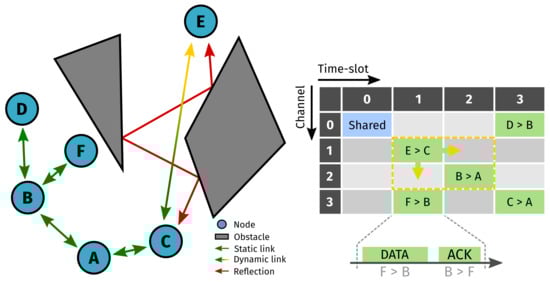
Figure 1.
Example of a small Time Slotted Channel Hopping (TSCH) network. Due to multi-path fading, the dynamic link between nodes E and C may revert to a modulation scheme with lower data-rate and wider bandwidth, causing the link to expand into the time/frequency space of adjacent slots. Note this figure does not represent a schedule, but rather its result in time and frequency.
While IEEE 802.15.4 transceivers are increasingly configurable, many TSCH deployments use network-wide, static PHY configurations. Since each modulation scheme has different characteristics in terms of robustness against interference and fading, a static approach is limited to the weakest link. Alternatively, we can dynamically re-configure the PHY of link endpoints according to local operating conditions. The use of multiple modulation schemes in response to heterogeneous and/or dynamic environments is called modulation diversity. Together with frequency diversity, modulation diversity can provide even better multi-path fading characteristics, which is the main concern in industrial sites with large metallic obstacles such as chemical plants, ship compartments, and container terminals.
When modulation schemes differ in data-rate and/or bandwidth, scheduling (i.e., assigning links to node-pairs) must account for this through mechanisms like slot and channel bonding [5]. For example, due to multi-path fading, the link between nodes E and C of Figure 1 may revert to a modulation scheme with lower data-rate and wider bandwidth, causing links to expand in time/frequency space. Typically one would “solve” resulting overlap (e.g., with the link between nodes B and A) by rebuilding the schedule. Alternatively, some space may be re-used to improve resource efficiency while partially preserving the benefits of modulation diversity (by “partially” we mean that spatial re-use will inevitably result in some degradation). Hence, in a first effort towards combining spatial re-use and modulation diversity, we measured the mutual interference robustness (by “mutual” we mean that PHY configurations are tested against one another, as well as themselves, in order to simulate a scenario wherein two transmissions overlap in time and frequency) of four IEEE 802.15.4 Smart Utility Network (SUN) Orthogonal Frequency Division Multiplexing (OFDM) [1] (pp. 512–535) configurations (introduced by IEEE 802.15.4g [6]). As such, our main contributions are:
- a setup (based on related work, see Section 2) that facilitates mutual interference robustness measurements for IEEE 802.15.4 SUN-OFDM;
- to our knowledge, the first in-depth analysis of partially overlapping IEEE 802.15.4 SUN-OFDM transmissions;
- a data-set for use with, e.g., state-of-the-art technology classification and slot/channel bonding to introduce controlled time/frequency overlap into a TSCH schedule.
This paper explains the choice for specific SUN-OFDM schemes and describes the experimental setup (and testing scenarios) in Section 3 and Section 4. It then goes on to present experimental results and discusses their relevance towards reliable and efficient TSCH networks (through modulation diversity and spatial re-use) for each testing scenario in Section 5, before concluding with some global directives towards that same goal and giving future perspectives in Section 6.
2. Related Work
The motivation for researching interference effects in WSNs is commonly related to an expected interference scenario. In a broad sense, inter-technology interference constitutes all interfering signals, at a given receiver, originating from distinct wireless networking technologies. Often (≠always) this boils down to inter-network interference, i.e., from sources other than the nodes within a single connected network. Similarly, intra-technology interference originates from (near) identical wireless networking technologies, while intra-network interference constitutes all interfering signals (at a given receiving node) originating from other nodes within the same wireless network.
One must first select a “general approach” before committing to an evaluation method designed to reflect a given interference scenario. While simulations and theoretical models are fine for IEEE 802.15.4 Offset Quadrature Phase Shift Keying (OQPSK) [1] (pp. 411–417), IEEE 802.15.4 SUN-OFDM is significantly more complex. Therefore, simulators like NS-3 [7] abstract interfering OFDM signals as white noise, a pessimistic assumption as shown by Fuxjaeger and Ruehrup [8]. This further emphasizes that any practical interference model needs to be validated with real data. Hence, we opted for an empirical approach instead, which implies a physical experimental setup consisting of (at least) two transmitting and one receiving node(s). Of the transmitting nodes, one typically transmits “useful transmissions”, while other transmitters send out interfering signals. In general, a number of useful transmissions are sent to a receiver under the influence of time-offset interference, after which certain metrics are inferred from received transmissions.
Table 1 lists relevant empirical approaches in terms of general testing principles. For example, the setup from Haxhibeqiri et al. [9] (Figure 1) contains a µ-controller which handles the transmission timings of a single LoRa [10] transmitter and a single interferer. The Radio Frequency (RF) output of each transmitter connects to its own controllable attenuator. These attenuated signals are then combined and sent to the LoRa receiver. To mitigate the influence of external interference, transmitters/receivers are placed in RF-shielded boxes and (presumably) all RF connections are made with shielded coaxial cables. Sixteen different tests were performed for every interfering technology (i.e., SigFox [11], Z-Wave [12] and IO-Homecontrol): one for each combination of four time-offsets (previous research efforts showed that the impact of interference largely depends on which part of a LoRa transmission it occurs in [13]), two Signal to Interference Ratios (SIRs) (−10 dB & +10 dB), and two LoRa spreading factors (SF7 & SF12). Each test ran long enough to transmit ≈ 100 LoRa physical layer (PHY) Protocol Data Units (PPDUs). Conclusions were drawn based on the measured Packet Loss Rate (PLR).

Table 1.
Summarized comparison of empirical interference robustness evaluation techniques for Wireless Sensor Networks (WSNs).
In a secondary effort, the effect of interference starting during the LoRa preamble was investigated for ten SIR levels between −25 dB and +25 dB (instead of two), all using the same setup/testing procedure. As pointed out by Fuxjaeger and Ruehrup [8], testing at different SIR levels is imperative to characterizing what is known as the capture effect, i.e., the possibility that “the collision of two [or more] frames in a shared channel may not destroy both frames.” [19] (p. 19). Instead, the PLR is often erroneously assumed to always be one when interference occurs during the useful transmission’s preamble and the SIR is below a certain threshold. In reality, at high enough SIR levels (≤threshold), some transmissions may successfully decode because the receiver was able to synchronize. Partial overlap in the frequency spectrum and/or dissimilar modulation schemes only add to the relevance of testing at different SIR levels. Given state-of-the-art technology classification [20] and ever more capable transceivers, future WSN deployments will likely utilize such data to make informed spectrum decisions in both inter- and intra-network interference scenarios, for example, when building a resource efficient TSCH schedule whilst coping with local operating conditions through modulation diversity in combination with spatial re-use (see Section 1).
Similarly, Mikhaylov et al. [14] designed an experimental setup [14] (Figure 1) wherein three LoRaWAN™ certified devices (i.e., supporting all Data Rates (DRs) defined in [17] (Table 6)) act as a useful transmitter (abbreviated “UTX”), an interferer, and a receiver respectively. Again, both transmitter RF outputs are attenuated, combined, and sent to the LoRa receiver over coaxial cabling. Despite the absence of RF shielding enclosures, the authors do specify external interference as a reason for not transmitting over-the-air. However, they also cite it as a means of avoiding duty cycle regulations [21]. In addition, different SIRs were achieved by varying transmit power with all attenuators fixed to 20 dB.
In a first testing phase, the UTX sent 2000 PPDUs for each combination of five transmit power settings and eight LoRaWAN™ DRs. Each PPDU contained a random MAC payload of random (bounded) length, and hence was of random (bounded) duration. In addition, the inter-PPDU delay was randomly chosen within a bounded interval. In a second phase, an interferer was added, using the same operating principles as the UTX. For each test combination (8 interferer DRs × 8 transmitter DRs × 9 SIRs) the Packet Error Rate (PER) was calculated based on 2000 useful transmissions.
Through random payload lengths and delays, and a large test size, the useful transmission parts targeted by interference and the percentages of time-overlap, are nearly equally represented. This is arguably an accurate representation of an inter-network interference scenario wherein interference transmit times are unknown. Alternatively, you could assess a PHYs robustness against intra-network interference by targeting parts of a useful transmission, provided you intend to use a synchronized MAC protocol. Regardless of its improved performance over pure ALOHA under intra-technology interference [13], the LoRaWAN™ MAC protocol remains random access in nature. As such, although Mikhaylov et al. [14] discuss the impact of intra-network interference on the scalability of LoRaWAN™ networks, its ALOHA-like MAC protocol implies randomly distributed interference (in time). This does not mean that a targeted interference study is irrelevant for LoRa, since it does not mandate use of LoRaWAN™.
As a final remark, the first testing phase shows that, with LoRa, the Packet Reception Rate (PRR) is not 100% for SIR . Hence, it is probably a good idea to establish such baseline before introducing interference in order to have a complete picture of each modulation scheme’s reliability.
In another recent study, Tuset-Peiró et al. [15] evaluate the robustness of SUN-OFDM against legacy (i.e., non-SUN) IEEE 802.15.4 OQPSK and vice versa. Besides legacy OQPSK, four OFDM option/Modulation and Coding Scheme (MCS) combinations were chosen. Their setup [15] (Figure 3) is similar to [14] (Figure 1), the main differences being: the use of RF shielding enclosures like in [9] (Figure 3), and the near 100% time-overlap between interference and useful transmissions. Much akin to [14], the useful transmit power was fixed while the interferer was first turned off (SIR ) before its transmit power was varied. Additionally, the effect on different useful PHY payload lengths was measured. For each test combination (5 interferer PHYs × 5 transmitter PHYs × 20 SIRs × 2 PHY payload lengths), the Packet Delivery Rate (PDR) was calculated based on 1000 useful transmissions.
The premise behind ≈100% time-overlap is similar to [14]: it does not target specific parts of a useful transmission. However, ≈100% overlap requires a smaller test size as opposed to when you would need sufficient messages to assure that all time-overlaps are roughly equally represented (as is the case in [14]). In addition, it removes the need for synchronization between interferer and UTX. While ≈100% time-overlap constitutes worst-case performance in every scenario, it is arguably best suited for evaluating interference robustness assuming unknown interference transmit times.
Notice how these methods are limited to measuring the PER (or derivatives thereof). While one could determine the Bit Error Rate (BER) the same way, it would require an enormous amount of useful transmissions because the probability of bit error is low. In addition, some metrics require low-level access which commercial transceivers do not provide. In order to also measure the Chip Error Rate (CER) of IEEE 802.15.4 OQPSK transmissions under Co-Channel Interference (CCI) (Pešović and Planinšič [16] identify CCI as an issue in legacy IEEE 802.15.4-2011 [22] networks because Carrier Sense Multiple Access with Collision Avoidance (CSMA/CA) [22] (pp. 21–23) is sensitive to hidden node collisions without the addition of Request to Send/Clear to Send (RTS/CTS)), Pešović and Planinšič [16] programmed a Software Defined Radio (SDR) as an OQPSK receiver. Besides the receiver, their setup [16] (Figure 12) consists of a UTX and an interferer, each transmitting PPDUs with a 20 byte PHY payload at 10 ms inter-PPDU delay. A 192 µs offset aligns the start of each interfering transmission with the start of a useful transmission’s PHY payload, thus allowing better receiver synchronization [1] (p. 411). However, successful synchronization/demodulation also depends on background noise. As error probability is expressed in function of average bit-energy over noise-power spectral density , the authors omitted RF shielding to allow comparison with empirically obtained error rates. By varying the transmit power of the UTX and interferer between tests, the CER and PER were measured for different SIRs at certain levels. A baseline (SIR ) was also obtained, but only for CER measurements at a seemingly arbitrary number of four levels.
While the authors explicitly mention the importance of carrier-, frame-, and chip synchronization, they only cause interference during the PHY payload. Presumably because their theoretical models/simulation results assume coherent detection and accurate sample times. As we explained before, targeted interference is not necessarily an accurate reflection of reality, unless it concerns controlled intra-network interference. What is more, especially at low levels, background noise alone may prevent proper synchronization, before interference even occurs (i.e., during the PHY payload). As such, Pešović and Planinšič [16] make note of deviations of experimental results from expected theoretical values (at low ) due to insufficient synchronization.
3. IEEE 802.15.4 SUN-OFDM
In the search for improved robustness against local fading phenomena, over traditional (static) TSCH deployments, SUN-OFDM is an excellent candidate. With OFDM, data is transmitted in parallel over orthogonally spaced sub-carriers [23] (pp. 199–224). The reasoning behind it is that all waves are subject to multi-path. A typical solution is to increase symbol duration. However, subsequently increasing the amount of bits per symbol to achieve similar data rates often requires an unreasonable Signal to Noise Ratio (SNR) [18] (pp. 74–84). Combining parallel transmissions with slow symbol rates solves this. The neat thing about the orthogonality aspect of OFDM is that it allows for parallel, low symbol-rate transmissions without the bandwidth requirement of non-orthogonal systems. For SUN-OFDM, both the carrier spacing and OFDM symbol rate are constant, while the data rate can be found with (1) and the information in Table 2.
where:
| OFDM data rate | ||
| number of data sub-carriers | ||
| coded payload bits/sub-carrier | ||
| sub-carrier convolution code rate | ||
| frequency repetition | ||
| OFDM symbol rate | ||
| uncoded payload bits/OFDM symbol |
Table 2.
Properties of selected IEEE 802.15.4 Smart Utility Network (SUN) Orthogonal Frequency Division Multiplexing (OFDM) physical layer (PHY) configurations.
Figure 2 depicts the format of a SUN-OFDM PPDU or “frame”. Note that, strictly speaking, the frame designates the PHY Service Data Unit (PSDU) while the PPDU is called a bit-sequence. For our purposes we use it in both cases, provided the context is sufficiently clear. By definition, a PPDU contains a PSDU preceded by a preamble/header and appended with tail/padding bits of sorts. With SUN-OFDM, the PHY frame header (PFHR) consists of a synchronisation header (SHR) and PHY header (PHR). The SHR contains two preambles, a Short Training Field (STF) and Long Training Field (LTF), which are four and two OFDM symbols long respectively [24] (p. 5). The PHR specifies the radio configuration needed to receive the PHY payload. It is 36 bits long and is always transmitted using the lowest MCS value for a given OFDM option [1] (Table 21-9). Assuming an interleaving depth of one OFDM symbol (which was true in our case), the number of OFDM symbols in the PFHR equals , with the amount of uncoded payload bits/OFDM symbol for the lowest MCS value (see (1)). The PSDU supports a length of ≤2047 bytes, which is well over the ≥1280 byte IPv6 MTU and thus removes the need for link-layer fragmentation. Finally, the PPDU tail contains six zero-bits to return the convolutional encoder to its zero-state, while zero-padding is done by rounding up the payload length to a multiple of Ndbps (see (1)).
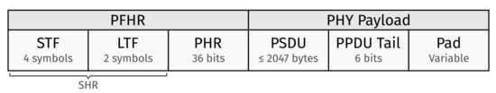
Figure 2.
Format of a Smart Utility Network (SUN) Orthogonal Frequency Division Multiplexing (OFDM) physical layer (PHY) Protocol Data Unit (PPDU). Note that we define the PHY frame header (PFHR) as the combination of the synchronisation header (SHR) and PHY header (PHR).
This brings us to the MCSs we selected for interference robustness evaluation, as listed in Table 2. Apart from the modulation/coding benefits of lower MCS values (within a SUN-OFDM option), our selection was largely based on data rate and bandwidth doubling so that our findings may facilitate further research efforts into slot and channel bonding respectively. In addition, the SUN-OFDM PSDU length (≤2047 bytes) compared to legacy OQPSK (≤127 bytes) may also facilitate slot-bonding based on double-length transmissions at the same data rate (at the expense of doubling the bandwidth). Indeed, at a constant BER, frequency repetition can largely make up for the increase in PER you would normally get when increasing the PSDU size as demonstrated by Muñoz et al. [25].
Finally, we note that Tuset-Peiró et al. [4] found SUN-OFDM to perform worse than SUN Frequency Shift Keying (FSK) [1] (pp. 493–511) and SUN-OQPSK (≠legacy OQPSK) in a multi-path prone environment (in the 863–870 MHz range). However, their hardware was limited to a transmit power of 9 dBm for SUN-OFDM while SUN-FSK and SUN-OQPSK were transmitted at ≈15 dBm. Therefore their results should be interpreted as an assessment of hardware capability rather than a comparison of PHY performance. With one narrow exception, all bands in the 863–870 MHz range limit the radiated power to ≤25 mW (≈14 dBm) [26] (Annex 1), [27] (Annex B). As such, only SUN-OFDM has room for improvement. In anticipation of hardware that can transmit SUN-OFDM at 14 dBm, we’re convinced it remains the way forward in multi-path prone environments (assuming the range requirements are such that the sensitivity deficit of SUN-OFDM compared to SUN-FSK/SUN-OQPSK is not relevant). Contrary to some SUN-FSK modes, SUN-OQPSK is currently not a contender for channel bonding, because it offers only three channels at different center frequencies than SUN-OFDM/SUN-FSK. However, this may change in future versions of the standard as indicated by amendment IEEE 802.15.4v-2017 [28], possibly warranting further investigation in future research efforts.
4. Materials and Methods
As explained in Section 1 and Section 2, we anticipate an intra-technology/intra-network interference scenario wherein time/frequency overlap occurs at known instants due to the combination of modulation diversity and spatial re-use in future TSCH deployments. This implies a targeted time-overlap strategy. Hence, our setup (see Figure 3) offers precise control over the timing offset between a UTX and an interferer. More specifically: a Zolertia RE-Mote [29], running RIOT-OS [30], sends out pulses on two of its pins. The time-offset between rising edges, consisting of an average and (bounded) random component, and the amount of pulse-pairs are configurable over a serial connection. Note that the time-period between consecutive pulse-pairs is fixed to 500 ms.
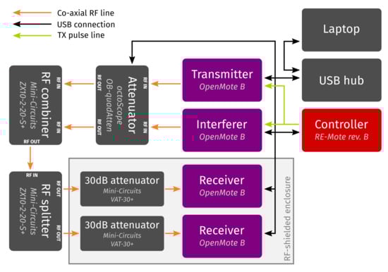
Figure 3.
Measurement setup for robustness evaluation of SUN-OFDM against intra-technology/ intra-network interference. A µ-controller handles transmission timings and all Radio Frequency (RF) connections are shielded co-axial cables. Note the RF shielding enclosure around the receivers to block external interference sources.
Four OpenMote-B nodes [31], running a custom RIOT-OS application, perform PPDU transmission/reception. The PSDU size, destination address, and current PHY configuration are all shell configurable. By default, these devices are in receiver mode and they’ll write all received PSDUs to the shell. However, when a rising edge is presented to one of its pins, a PSDU of the configured byte-size is sent to the previously specified destination address using the currently selected SUN-OFDM option + MCS. Given the chosen configuration, (1), and Table 2, the transmission duration (i.e., on-air time) of any transmission is found with (2). All RF operations are performed through the sub-GHz interface of an on-board Microchip AT86RF215 transceiver [32].
where:
| transmission duration | ||
| OFDM symbols in PHY frame header | ||
| OFDM symbol rate | ||
| uncoded data bits | ||
| uncoded tail bits | ||
| uncoded payload bits/OFDM symbol | ||
| PHY frame header duration | ||
| PHY payload duration |
Two OpenMote-B nodes are used as UTX and interferer respectively. The interferer’s purpose is to transmit a PPDU of a certain size with a certain (average) time-offset in respect to a given useful transmission. This offset is facilitated by connecting the timing-controller’s pulse pins to the corresponding transmit pin of the respective device. Both receiving OpenMote-B nodes reside in an RF shielded enclosure to block external interference sources.
The sub-GHz RF outputs of both interferer and UTX are connected to an octoScope OB-quadAtten [33]. This programmable attenuator allows us to adjust the attenuation of either transmitted signal to achieve a certain SIR without the need for transmit power calibration. As such, we fixed the transmit power to ≈ 9 dBm by setting the AT86RF215’s RF09_PAC register to 0x7E [15] (Table 3), [32] (Figure 11-2). After attenuation, signals are combined and then duplicated with two Mini-Circuits ZX10-2-20-S+ RF combiners/splitters [34] before both duplicated combined signals are once again attenuated by 30 dB through a Mini-Circuits VAT-30+ [35] fixed attenuator.
A single test begins by setting PSDU sizes, destination addresses, and PHY configurations. Since both devices send PPDUs to a corresponding receiver, each transmitting/receiving node pair must use the same PHY configuration. Separate receivers allow to measure the PRR of both transmissions. Finally, the timing offset (i.e., a fixed average and the absolute bound of a random component) and the amount of pulse-pairs (i.e., the amount of useful/interfering PPDUs per test) are passed to the timing controller which is thereafter instructed to start generating pulse-pairs. In our case, the UTX and interferer sent out 400 PPDUs each for every test. Given the receiver output dumps, the PRR then equals the number of transmissions received divided by 400. Given a number of PHY configurations, timing offsets, and PSDU sizes, a Python script (running on the laptop) partially automates testing by looping through all combinations thereof. Note that all transmissions occur in channel zero of their respective PHY configuration. Table 2 lists the relevant center frequency and channel spacing.
In practice, our setup facilitates any conceivable time-overlap strategy. Nonetheless, in anticipation of intra-network interference with overlap at known instants, two testing scenarios in particular allow us to make statements about the targeted interference robustness of aforementioned set of PHY configurations. More specifically, Section 4.1 explains the testing procedure for interference occurring during the PHY payload, while Section 4.2 makes a similar case for interference during the SUN-OFDM PHY frame header. All firm- and software used in our setup is available as Supplementary Materials.
4.1. Interference during PHY Payload
In this case, the UTX PSDU size was fixed to 255 bytes while the interferer PSDU size varied to achieve a certain time-overlap with the useful PPDU’s PHY payload. Given the interferer PSDU size, the timing offset needed to align an interfering PPDU in the middle of a useful PPDU’s PHY payload is obtained by calculating with (2) and substituting into (3). Notice the addition of a random offset within to account for the influence of phase differences between UTX/interferer. The resulting time-overlap percentage is given by (4). Figure 4 gives a visual representation in the time domain.
where:
| time-offset between transmissions | ||
| useful transmission duration | ||
| PHY frame header duration | ||
| interference transmission duration | ||
| random offset | ||
| time overlap with PHY payload |
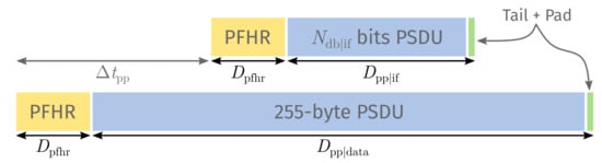
Figure 4.
Time-domain overlap between a useful PPDU’s PHY payload (bottom) and an interfering PPDU (top). The offset follows from the interference transmit duration and its alignment in the center of the useful PHY payload.
From Table 2 and (1) it follows that for SUN-OFDM O4 MCS2 and O3 MCS1. Hence, given the PHR is transmitted using the lowest MCS value for a given OFDM option, and thus equals 1.44 ms for all considered transmissions. Similarly, for O4 MCS3 and O3 MCS2. Given a 255-byte PSDU, and following (2), 42.36 ms for O4 MCS2/O3 MCS1, and 21.96 ms for O4 MCS3/O3 MCS2.
Notice how variable-length zero padding and the constant-length PFHR and PPDU tail means that nor multiplying nor dividing the PSDU size by a certain factor results in a transmission duration divided by exactly that same factor. Moreover, our RIOT-OS application expects a PSDU size ≥ 19 bytes, i.e., an empty MAC frame with a 15 byte header (short destination address + omitted source Personal Area Network (PAN) identifier) and four bytes Frame Check Sequence (FCS) [1] (pp. 151–158). Given these limitations, we decided on a set of interferer PSDU sizes resulting in payload overlaps as close to 25%, 50%, and 75% as possible. In addition we configured the interferer with a 21 byte PSDU, i.e., the size of an enhanced acknowledgement (Enh-Ack) frame in case of 19 bytes MAC header + FCS. Table 3 lists all interferer PSDU sizes and corresponding expected transmission timing offsets/PHY payload overlaps used.
Table 3.
Timing offsets and payload overlaps for given interferer PHY Service Data Unit (PSDU) sizes.
In summary, for each run of our Python script, 400 useful/interfering PPDUs are transmitted for each combination of 4 interferer PHYs × 4 UTX PHYs × 4 interferer PSDU sizes = 64 tests. Before each automated run, the attenuation of the interferer’s RF output is set to the next value dB, while attenuation of the UTX’s RF output remains fixed to 3 dB. Hence, we ran 64 tests for each SIR dB. In addition, we first set a baseline for every relevant combination of PHY configuration and PSDU size. This makes for a total of 348 tests (64 × 5 SIRs + 28 baselines). The extent of our campaign is highlighted by Table 4.
Table 4.
Extent of our measurement campaign.
4.2. Interference during PHY Frame Header
In this case, both the UTX and interferer PSDU size were fixed to 255 bytes. Here, a time-overlap is the result of shifting an interfering PPDU into the useful PFHR by an integer amount of OFDM symbols. Given x overlapping symbols, with , the required timing-offset and resulting PFHR overlap percentage is given by (5) and (6) respectively. Figure 5 provides a visual representation in the time domain.
where:
| time-offset between transmissions | ||
| x | number of overlapping symbols with | |
| OFDM symbol rate | ||
| interference transmission duration | ||
| random offset | ||
| time overlap with PHY frame header | ||
| PHY frame header duration |
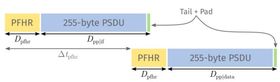
Figure 5.
Time-domain overlap between a useful PPDU’s PFHR (bottom) and an interfering PPDU (top). The offset follows from the interference transmit duration and the number of overlapping symbols with the useful PFHR.
Given the ≥ 19 bytes frame size, we cannot target individual parts of the PFHR other than the STF. Instead, we aligned the tail-end of interfering transmissions with the OFDM symbol boundaries () of the three PFHR elements from Figure 2, that is, the STF, LTF, and PHR. Table 5 lists the number of overlapping symbols and corresponding expected transmission timing offsets/expected PFHR overlaps used.
Table 5.
Timing offsets and PHY frame header (PFHR) overlaps for given number of overlapping symbols.
In similar fashion to Section 4.1, each run of our Python script results in 48 tests (16 PHY combinations × 3 symbol overlaps) of 400 useful/interfering PPDUs each. Once again, before each automated run, the attenuation of the interferer’s RF output is set to the next value dB, while attenuation of the UTX’s RF output remains fixed to 3 dB, meaning SIR dB. This makes for a total of 240 tests (48 × 5 SIRs). Again, the extent of our campaign is highlighted by Table 4. Note that we recycled the baseline test results from Section 4.1.
5. Results and Discussion
Before making statements about results and their relevance, we must first provide the context to do so. Hence, for the sake of abstraction, imagine both UTX and interferer use a single phase-modulated carrier, instead of SUN-OFDM (although all configurations in Table 2 use phase-modulated sub-carriers, certain (optional) configurations use 16 Quadrature Amplitude Modulation (16-QAM) sub-carriers [1] (p. 520)). In that case, as explained by Pešović and Planinšič [16] (p. 46): “The interfering signal arrives at the receiver with time varying phase offset , caused by initial phase offset and by frequency offset caused by the difference between the local oscillators in the receiver and in the source of the interfering signal.” In other words, interference causes constellation points to move along the in-phase (I) and quadrature (Q) axes as a function of phase difference and the interfering signal energy [36] (p. 307) at the useful receiver. Since the probability of a certain shift along a given axis follows a known distribution, one could then express the probability of incorrectly interpreting a modulation symbol in terms of , and derive packet error probability from there.
Moving to phase-modulated sub-carriers implies each useful sub-carrier experiences different levels of from each interfering sub-carrier. For example, Figure 6 shows the misaligned sub-carriers of SUN-OFDM O4 and O3 (not all sub-carriers necessarily use the same modulation scheme, since pilot tones are always Binary PSK (BPSK)-modulated, and the set of sub-carriers used as pilot changes over time [1] (pp. 527–530)). In general, the closer interfering and useful sub-carriers align, the larger the contribution, and the harder it is for the receiver to correctly interpret useful symbols. That said, some PHY configurations use only part of their data sub-carriers to transmit each consecutive set of modulation symbols, while a phase rotated version of the same symbol set is replicated on the remaining data tones. At the receiver, all replicated versions of a given symbol are first equalized and then de-rotated, after which the average of these equalized/de-rotated symbols is passed to the modulation symbol de-mapper [37] (p. 552). This mechanism is called frequency repetition, and it can (partially) negate the negative impact of interference.
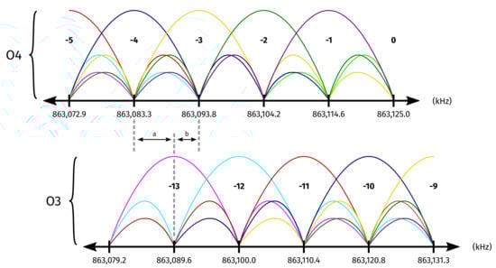
Figure 6.
Frequency domain overlap between modulated sub-carriers of SUN-OFDM O4 and O3 PHYs. For example, O3 sub-carrier −13 is spaced a = 6250 Hz from O4 sub-carrier −4 and b ≈ 4167 Hz from O4 sub-carrier −3.
Besides frequency repetition and sub-carrier alignment, a third factor is of particular interest. Since QPSK behaves as if both the I and Q carrier are (independently) BPSK modulated, the probability of incorrectly interpreting a coded bit is nearly identical for QPSK and BPSK. However, achieving this requires twice the power, since QPSK transmits two coded bits at a time. For this purpose, SUN-OFDM mandates QPSK modulation symbols be multiplied by a factor to achieve the same average power as BPSK modulated sub-carriers [1] (pp. 522–523). In that case, the for QPSK is only half that of BPSK and the probability of a coded bit error increases significantly (but not necessarily by a factor of two), that is, under the influence of white noise and (presumably) phase-modulated interference.
Corresponding to Section 4, Section 5.1 and Section 5.2 present and discuss the results of targeted interference testing during the PHY payload and PFHR (of given SUN-OFDM transmissions) respectively. The sub-figures of Figure 7 depict the PRR of a given transmission in a given overlap scenario. The primary x and y axis list the interferer and UTX PHY configuration respectively so that each black rectangle contains the PRR for every SIR (secondary x axis) and time overlap (secondary y axis) combination for the given PHY combination. Note that the curated data files used to generate these figures, as well as the code needed to do so, are available as Supplementary Materials.
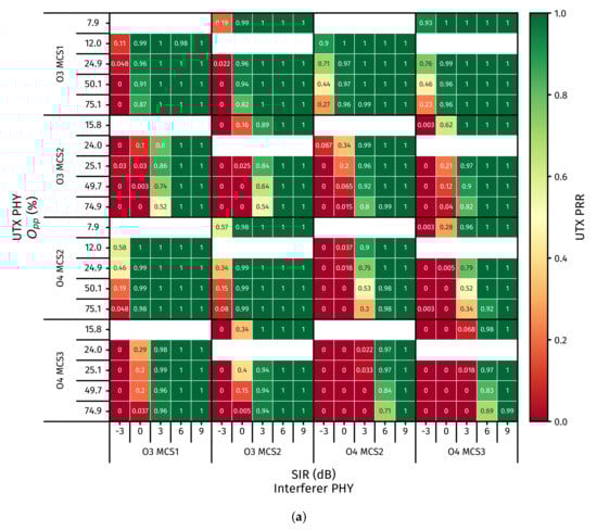
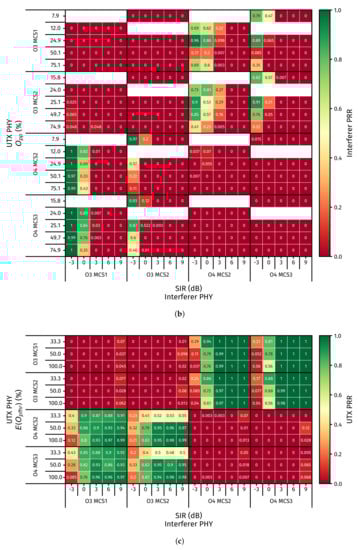
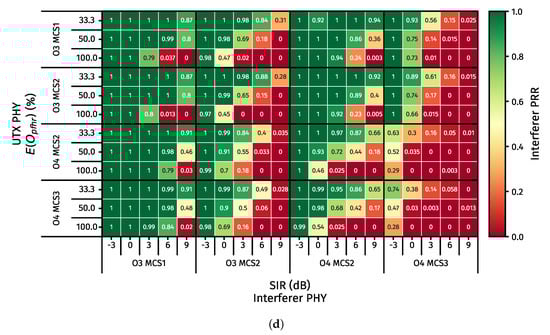
Figure 7.
Results of targeted interference experiments in anticipation of deterministic intra-network interference. Each sub-figure depicts the Packet Reception Rate (PRR) (with one being 100% successful reception) of a given transmission in a given overlap scenario. The primary x and y axis respectively show the interferer and useful transmitter (UTX) PHY configuration so that each black rectangle contains the PRR for every Signal to Interference Ratio (SIR) (secondary x axis) and overlap (secondary y axis) combination for the corresponding PHY combination. Since an enhanced acknowledgement (Enh-Ack) is of fixed size, differs between PHY combinations. Hence, non applicable is left white. (a) UTX PRR with overlap in PHY payload. (b) Interferer PRR with overlap in PHY payload. (c) UTX PRR with overlap in PFHR. (d) Interferer PRR with overlap in PFHR.
5.1. Interference during PHY Payload
5.1.1. Results
For a complete picture, we first set a baseline (SIR = ∞) and found PRR = 1 for every relevant PHY configuration/PSDU size. Hence, we omitted a graph to save space. The UTX PRR (PRRUTX) and interferer PRR (PRRIF) of the PHY payload overlap scenario from Section 4.1 are given by Figure 7a,b respectively. In a nutshell:
- for O3 MCS1 useful transmissions in particular, PRRUTX ≥ 0.96 in 93.8% of cases where SIR ≥ 0 dB;
- for O4 MCS2 useful transmissions under influence of O3 MCS1/MCS2 interference, PRRUTX ≥ 0.98 in 100% of cases where SIR ≥ 0 dB;
- for O4 MCS2 interfering with O3 MCS1/MCS2, PRRIF ≥ 0.57 in 68.8% of cases where SIR ≤ 0 dB;
- for O3 MCS1 interfering with O4 MCS2/MCS3, PRRIF ≥ 0.69 in 81.3% of cases where SIR ≤ 0 dB;
- for every UTX/interferer PHY combination, PRRUTX ≥ 0.97 in 96.1% of cases where SIR ≥ 6 dB.
As such, O3 MCS1 seems especially resilient to O4 MCS2 and MCS3 interference and the same is true for O4 MCS2 w.r.t. O3 MCS1/MCS2 interference. In similar fashion, PRRIF is highest for O4 MCS2 and O3 MCS1 interfering with O3 MCS1/MCS2 and O4 MCS2/MCS3 transmissions respectively. This is readily explained by the large frequency offset between O3 and O4 sub-carriers. Nonetheless, O3 MCS2 and O4 MCS3 perform worse than O3 MCS1 and O4 MCS2 in similar conditions, the difference between O3 MCS1 and O3 MCS2 being their data sub-carriers are BPSK and QPSK modulated respectively (remember the normalization), while the sole distinction between O4 MCS2 and O4 MCS3 is that the former uses frequency repetition.
Note that PRRUTX was also relatively high for O3 MCS1 in the presence of O3 MCS1/MCS2 interference (provided SIR ≥ 0 dB). While interfering sub-carriers are well (≠perfectly) aligned, the combination of BPSK modulated data carriers and frequency repetition gives O3 MCS1 a SIR advantage of >3 dB compared to just frequency repetition. In fact, PRRUTX is only slightly worse for O3 MCS1 than it is for O4 MCS2 in the same scenario, the difference being the misaligned interfering sub-carriers instead of BPSK modulated data tones. Nonetheless, this similarity is not reflected in PRRIF results. As will become clear in Section 5.2, since the interfering PPDU is completely encapsulated in the useful PHY payload (much akin to the 100% overlap strategy from [15]), PFHR overlap comes into play.
At first glance, our data confirms there is a SIR threshold (for each option & MCS combination) above which does not influence PRRUTX, as mentioned in [8]. However, as the gap between the SIR levels we tested at is high, we cannot draw such conclusions with certainty. Conversely, below said SIR threshold, PRRUTX seems to drop with increasing , until yet another SIR threshold is reached below which PRRUTX near instantly drops to zero as soon as the useful transmission encounters interference. Nonetheless, further testing at lower is needed to confirm these suspicions. For now, Section 5.2 may provide some clarity.
5.1.2. Discussion
Remember we ultimately want to improve the reliability of TSCH networks without sacrificing resource efficiency through modulation diversity and spatial re-use, and how this implies time/frequency overlap (at known instants). As such, both PRRUTX and PRRIF should be high under the same circumstances. Otherwise, what is the point of targeted interference if collisions (and subsequent re-transmissions) result in a less resource-efficient schedule? Hence, a schedule combining O3 MCS1 and O4 MCS2 transmissions seems promising when time overlap during the useful PHY payload is inevitable. Unfortunately, PRRIF performance is still poor for high SIR values.
That said, given both O3 MCS1 and O4 MCS2 have a 50 kbps data rate, the main trade-off centers around reliability (through modulation diversity) versus scaleability, as O3 MCS1 is presumably better equipped to deal with propagation impediments [38] at the expense of wider channels, and the more wide channels you have, the less overall channels you can support, even with targeted interference.
5.2. Interference during PHY Frame Header
5.2.1. Results
Similarly to Section 5.1.1, PRRUTX and PRRIF of the PFHR overlap scenario from Section 4.2 are given by Figure 7c,d respectively. In a nutshell:
- when both useful and interfering PHY are from the same option, PRRUTX ≤ 0.05 in 92.5% of all cases;
- for all O3 useful transmissions, under influence of O4 interference, PRRUTX ≥ 0.97 in 100% of cases where SIR ≥ 3 dB;
- for all O4 useful transmissions, under influence of O3 MCS1 interference, PRRUTX ≥ 0.85 in 87.5% of cases where SIR ≥ 0 dB.
As mentioned in Section 5.1.1, it is clear that when UTX and interferer use the same SUN-OFDM option (regardless of MCS), PRRUTX is almost non-existent. While heavily receiver-implementation dependent, the SHR fields are generally used for Carrier Frequency Offset (CFO) estimation/correction, and channel estimation/correction [37,39]. Since the SHR is transmitted on (a subset of) the same sub-carriers, the contribution remains high. As such, it makes sense that PRRUTX is low when UTX and interferer use the same option, especially when interfering with the STF, which also handles frame detection and synchronization [37,40]. Following the SHR, the PHR contains information essential to receiving the ensuing PHY payload (i.e., MCS level, PSDU length, and scrambler seed). Hence, it seems odd that PRRUTX increases for an increased PFHR overlap given UTX PHY = O4 MCS2/MCS3 and SIR ≥ 3 dB. However, Fuxjaeger and Ruehrup [8] (p. 220) have observed similar behavior.
Interference during the PFHR is vastly more detrimental to PRRUTX than interference during the PHY payload. However, since time-overlap percentages are expressed relative to the size/duration of the targeted interval, this may not be immediately clear. In order to solve this discrepancy, (7) calculates the overlap percentage w.r.t. the entire PPDU. From there it is clear that PRRUTX is much worse, even though is significantly lower.
where:
| time overlap with entire PPDU | ||
| time overlap with PHY payload | ||
| useful transmission duration | ||
| PHY frame header duration | ||
| time overlap with PHY frame header |
If you would multiply the SIR labels by −1 and re-write (7) to convert from to , the PRRIF heatmap of Figure 7d can also be interpreted as a PRRUTX heatmap for overlap during the PHY payload of the interfering PPDU. Since the resulting is much lower compared to Figure 7a, it allows us to “see” more clearly the increasing speed with which PRRUTX drops to zero in function of at increasingly lower SIR levels, until it happens nearly instantaneously.
5.2.2. Discussion
Again, in the interest of resource efficiency, both PRRUTX and PRRIF should be relatively high under the same circumstances. Similarly to Section 5.1.2, a schedule combining O3 MCS1 and O4 MCS2 transmissions seems most promising when time overlap during the useful PFHR is inevitable.
6. Conclusions and Perspectives
The fourth industrial revolution requires process monitoring on an unprecedented scale. Yet, industrial processes are often ill-suited for wired sensing. As such, many are turning to wireless alternatives. While IEEE 802.15.4 and its TSCH mode offer a great starting point, a static PHY is limited to the weakest link. Instead, one could re-configure link endpoints dynamically, according to context. However, resulting differences in data-rate and bandwidth cause links to coincide in time/frequency space, thereby degrading overall reliability if left unchecked. Nonetheless, to some extent, intentional spatial overlap (i.e., spatial re-use) can improve resource efficiency while partially preserving the benefits of modulation diversity. Hence, we measured the mutual interference robustness of four SUN-OFDM configurations, as a first step towards combining spatial re-use and modulation diversity.
In conclusion, from Section 5.1 and Section 5.2 it is clear that SUN-OFDM O3 MCS1 performs best in terms of the PRR of both useful and interfering transmissions versus: (1) SIR; and (2) the time-overlap percentage of interference with the PHY payload and frame header of a useful transmission, that is, under influence of O4 MCS2 interference. The same can be said for the reverse case, i.e., for O3 MCS1 interfering with O4 MCS2. Therefore, one should consider O3 MCS1 and O4 MCS2 for the development of a TSCH scheduler that supports modulation diversity through slot- and/or channel bonding without sacrificing (and possibly even improving) resource efficiency through spatial re-use, i.e., intra-network interference at known instants.
Naturally there is room for improvement here. For example, a useful extension to our efforts might be to introduce a controlled amount of white noise into the setup in order to also account for different levels like in [16]. However, noise should then be pseudo-randomly generated and added via co-axial equipment instead of using antennas. In addition, one could adopt practices from theoretical/simulated approaches. Specifically, measuring a useful transmission’s robustness against intra-network interference from multiple interferers at once [41] could lead to an even greater resource efficiency. Finally, we identify the need for a more thorough characterization of the standalone performance of the considered PHY configurations in industrial environments, much akin to [25].
Supplementary Materials
The following are available online at https://www.mdpi.com/2079-9292/9/10/1691/s1: the full code base (including instructions), and curated data files.
Author Contributions
Conceptualization, R.E., E.D.P. and J.H.; Methodology, R.E.; Software, R.E.; Investigation, R.E.; Project administration, E.D.P.; Supervision, E.D.P.; Funding acquisition, R.E. and E.D.P.; Writing—original draft, R.E.; Visualization, R.E.; Data curation, R.E.; Writing—review & editing, R.E., E.D.P., J.H., D.V.L., A.S., G.D. and J.F. All authors have read and agreed to the published version of this manuscript.
Funding
This research was made possible (in part) by the Research Foundation—Flanders (FWO) through strategic basic research grant 67684: SDR-Based Industrial IoT: Towards Ubiquitous Wireless Connectivity, and by the Internet of Shipping (ICON-IoS) project, which is co-financed by IMEC and the Flanders Innovation & Entrepreneurship agency.
Conflicts of Interest
The authors declare no conflict of interest.
Abbreviations
The following abbreviations are used in this manuscript:
| BER | Bit Error Rate |
| BPSK | Binary Phase Shift Keying |
| CA | Collision Avoidance |
| CCI | Co-Channel Interference |
| CER | Chip Error Rate |
| CFO | Carrier Frequency Offset |
| CSMA | Carrier Sense Multiple Access |
| CTS | Clear to Send |
| DR | Data Rate |
| Enh-Ack | enhanced acknowledgement |
| FCS | Frame Check Sequence |
| FSK | Frequency Shift Keying |
| I | in-phase |
| IoT | Internet of Things |
| LTF | Long Training Field |
| MAC | Medium Access Control |
| MCS | Modulation and Coding Scheme |
| OFDM | Orthogonal Frequency Division Multiplexing |
| OQPSK | Offset Quadrature Phase Shift Keying |
| PAN | Personal Area Network |
| PDR | Packet Delivery Rate |
| PER | Packet Error Rate |
| PFHR | PHY frame header |
| PHR | PHY header |
| PHY | physical layer |
| PLR | Packet Loss Rate |
| PPDU | PHY Protocol Data Unit |
| PRR | Packet Reception Rate |
| PSDU | PHY Service Data Unit |
| Q | quadrature |
| QAM | Quadrature Amplitude Modulation |
| QPSK | Quadrature Phase Shift Keying |
| RF | Radio Frequency |
| RTS | Request to Send |
| SDR | Software Defined Radio |
| SF | Spreading Factor |
| SHR | synchronization header |
| SIR | Signal to Interference Ratio |
| SNR | Signal to Noise Ratio |
| STF | Short Training Field |
| SUN | Smart Utility Network |
| TSCH | Time-Slotted Channel Hopping |
| UTX | useful transmitter |
| WSN | Wireless Sensor Network |
References
- IEEE Standard for Low-Rate Wireless Networks; IEEE Std 802.15.4-2015 (Revision of IEEE Std 802.15.4-2011); IEEE: Piscataway, NJ, USA, 2016; pp. 1–709.
- IEEE Standard for Local and Metropolitan Area Networks—Part 15.4: Low-Rate Wireless Personal Area Networks (LR-WPANs) Amendment 1: MAC Sublayer; IEEE Std 802.15.4e-2012 (Amendment to IEEE Std 802.15.4-2011); IEEE: Piscataway, NJ, USA, 2012; pp. 1–225.
- Proakis, J.G.; Salehi, M. Digital Communications, 5th ed.; McGraw-Hill: New York, NY, USA, 2008; ISBN 978-00-7295-716-7. [Google Scholar]
- Tuset-Peiró, P.; Gomes, R.D.; Thubert, P.; Vilajosana, X. Evaluating IEEE 802.15.4g SUN for Dependable Low-Power Wireless Communications In Industrial Scenarios. Preprints 2020, 2020020174. [Google Scholar] [CrossRef]
- Daneels, G.; Delgado, C.; Latré, S.; Famaey, J. Towards Slot Bonding for Adaptive MCS in IEEE 802.15.4e TSCH Networks. In Proceedings of the 2020 IEEE International Conference on Communications (ICC’20), Dublin, Ireland, 7–11 June 2020; pp. 1–7. [Google Scholar]
- IEEE Standard for Local and Metropolitan Area Networks—Part 15.4: Low-Rate Wireless Personal Area Networks (LR-WPANs) Amendment 3: Physical Layer (PHY) Specifications for Low-Data-Rate, Wireless, Smart Metering Utility Networks; IEEE Std 802.15.4g-2012 (Amendment to IEEE Std 802.15.4-2011); IEEE: Piscataway, NJ, USA, 2012; pp. 1–252.
- ns-3 Home Page. Available online: https://www.nsnam.org/ (accessed on 8 June 2020).
- Fuxjaeger, P.; Ruehrup, S. Validation of the NS-3 Interference Model for IEEE802.11 Networks. In Proceedings of the 8th IFIP Wireless and Mobile Networking Conference (WMNC’15), Munich, Germany, 5–7 October 2015; pp. 216–222. [Google Scholar]
- Haxhibeqiri, J.; Shahid, A.; Saelens, M.; Bauwens, J.; Jooris, B.; De Poorter, E.; Hoebeke, J. Sub-Gigahertz Inter-Technology Interference. How Harmful is it for LoRa? In Proceedings of the 2018 IEEE International Smart Cities Conference (ISC2’18), Kansas City, MO, USA, 16–19 September 2018; pp. 1–7. [Google Scholar]
- LoRa Modulation Basics; AN1200.22 (Rev. 2); Semtech: Camarillo, CA, USA, 2015; pp. 1–26.
- Sigfox Connected Objects: Radio Specifications; EP-SPECS (Rev. 1.5); Sigfox SA: Labège, France, 2020; pp. 1–43.
- Z-Wave Alliance. Z-Wave Mesh Network Protocol Specification. Available online: https://www.silabs.com/products/wireless/mesh-networking/z-wave/specification (accessed on 14 April 2020).
- Haxhibeqiri, J.; Van den Abeele, F.; Moerman, I.; Hoebeke, J. LoRa Scalability: A Simulation Model Based on Interference Measurements. Sensors 2017, 17, 1193. [Google Scholar] [CrossRef] [PubMed]
- Mikhaylov, K.; Petäjäjärvi, J.; Janhunen, J. On LoRaWAN Scalability: Empirical Evaluation of Susceptibility to Inter-Network Interference. In Proceedings of the 2017 European Conference on Networks and Communications (EuCNC’17), Oulu, Finland, 12–15 June 2017; pp. 1–6. [Google Scholar]
- Tuset-Peiró, P.; Vázquez-Gallego, F.; Muñoz, J.; Watteyne, T.; Alonso-Zarate, J.; Vilajosana, X. Experimental Interference Robustness Evaluation of IEEE 802.15.4-2015 OQPSK-DSSS and SUN-OFDM Physical Layers for Industrial Communications. Electronics 2019, 8, 1045. [Google Scholar] [CrossRef]
- Pešović, U.; Planinšič, P. Error probability model for IEEE 802.15.4 wireless communications in the presence of co-channel interference. Phys. Commun. 2017, 25, 43–53. [Google Scholar]
- LoRaWAN Regional Parameters; RP002-1.0.0 (Rev. 2-1.0.0); LoRa Alliance: Fremont, CA, USA, 2019; pp. 1–88.
- McCune, E. Practical Digital Wireless Signals, 1st ed.; Cambridge University Press: Cambridge, UK, 2010; ISBN 978-05-1167-538-6. [Google Scholar]
- Lee, J.; Kim, W.; Lee, S.J.; Jo, D.; Ryu, J.; Kwon, T.; Choi, Y. An Experimental Study on the Capture Effect in 802.11a Networks. In Proceedings of the Second ACM International Workshop on Wireless Network Testbeds, Experimental Evaluation and Characterization (WiNTECH’07), Montreal, QC, Canada, 9–14 September 2007; pp. 19–26. [Google Scholar]
- Shahid, A.; Fontaine, J.; Camelo, M.; Haxhibeqiri, J.; Saelens, M.; Khan, Z.; Moerman, I.; De Poorter, E. A Convolutional Neural Network Approach for Classification of LPWAN Technologies: Sigfox, LoRA and IEEE 802.15.4g. In Proceedings of the 16th Annual IEEE International Conference on Sensing, Communication and Networking (SECON ’19), Boston, MA, USA, 10–13 June 2019; pp. 1–8. [Google Scholar]
- Commission Implementing Decision (EU) 2017/1483 of 8 August 2017 Amending Decision 2006/771/EC on Harmonisation of the Radio Spectrum for Use by Short-Range Devices and Repealing Decision 2006/804/EC; 2017/1483/EC; European Commission: Brussels, Belgium, 2017; pp. 1–25. Available online: https://eur-lex.europa.eu/eli/dec_impl/2017/1483/oj (accessed on 20 May 2020).
- IEEE Standard for Local and Metropolitan Area Networks—Part 15.4: Low-Rate Wireless Personal Area Networks (LR-WPANs); IEEE Std 802.15.4-2011 (Revision of IEEE Std 802.15.4-2006); IEEE: Piscataway, NJ, USA, 2011; pp. 1–314.
- Pischella, M.; Le Ruyet, D. Digital Communications 2: Digital Modulations, 1st ed.; ISTE: London, UK, 2015; ISBN 978-18-4821-846-8. [Google Scholar]
- Nguyen, H.; Le, N.T.; Hoan, N.C.; Jang, Y.M. Real-Time Mitigation of the Mobility Effect for IEEE 802.15.4g SUN MR-OFDM. Appl. Sci. 2019, 9, 3289. [Google Scholar] [CrossRef]
- Muñoz, J.; Riou, E.; Vilajosana, X.; Muhlethaler, P.; Watteyne, T. Overview of IEEE802.15.4g OFDM and its Applicability to Smart Building Applications. In Proceedings of the 2018 Wireless Days (WD’18), Dubai, UAE, 3–5 April 2018; pp. 123–130. [Google Scholar]
- Relating to the Use of Short Range Devices (SRD); ERC Recommendation 70-03; CEPT-ECC: Copenhagen, Denmark, 20 June 2019; pp. 1–86.
- Short Range Devices (SRD) Operating in the Frequency Range 25 MHz to 1000 MHz; Part 2: Harmonised Standard for Access to Radio Spectrum for Non Specific Radio Equipment; EN 300 220-2 (Rev. 3.2.1); ETSI: Sophia-Antipolis, France, 2018; pp. 1–33.
- IEEE Standard for Low-Rate Wireless Networks—Amendment 5: Enabling/Updating the Use of Regional Sub-GHz Bands; IEEE Std 802.15.4v-2017 (Amendment to IEEE Std 802.15.4-2015, as amended by IEEE Std 802.15.4n-2016, IEEE Std 802.15.4q-2016, IEEE Std 802.15.4u-2016, and IEEE Std 802.15.4t-2017); IEEE: Piscataway, NJ, USA, 2017; pp. 1–35.
- Zolertia. Zolertia RE-Mote platform. Available online: https://github.com/Zolertia/Resources/wiki/RE-Mote (accessed on 22 May 2020).
- Freie Universität Berlin. RIOT—The friendly Operating System for the Internet of Things. Available online: https://www.riot-os.org (accessed on 20 May 2020).
- Industrial Shields. Open Mote B User Guide (Rev. 0). 2019. Available online: https://www.industrialshields.com/web/content?model=ir.attachment&field=datas&id=102921& (accessed on 3 September 2020).
- Microchip. AT86RF215 Device Family: Sub-1GHz/2.4GHz Transceiver and I/Q Radio for IEEE Std 802.15.4-2015, IEEE Std 802.15.4g-2012, ETSI TS 102 887-1 (Rev. 42415E). 2016. Available online: http://ww1.microchip.com/downloads/en/devicedoc/atmel-42415-wireless-at86rf215_datasheet.pdf (accessed on 3 September 2020).
- octoScope, Inc. quadAtten Programmable Attenuator. Available online: https://www.octoscope.com/English/Collaterals/Documents/quadAtten_datasheet.pdf (accessed on 3 September 2020).
- Mini-Circuits. ZX10-2-20-S+ Coaxial Power Splitter/Combiner (Rev. J). Available online: https://www.minicircuits.com/pdfs/ZX10-2-20-S+.pdf (accessed on 3 September 2020).
- Mini-Circuits. VAT-30+ Coaxial SMA Fixed Attenuator (Rev. H). Available online: https://www.minicircuits.com/pdfs/VAT-30+.pdf (accessed on 3 September 2020).
- Grami, A. Introduction to Digital Communications, 1st ed.; Academic Press: Cambridge, MA, USA, 2016; ISBN 978-01-2407-682-2. [Google Scholar]
- Alves, D.C.; da Silva, G.S.; de Lima, E.R.; Chaves, C.G.; Urdaneta, D.; Perez, T.; Garcia, M. Architecture design and implementation of key components of an OFDM transceiver for IEEE 802.15.4g. In Proceedings of the 2016 IEEE International Symposium on Circuits and Systems (ISCAS’16), Montréal, QC, Canada, 22–25 May 2016; pp. 550–553. [Google Scholar]
- Yoshida, S.; Ikegami, F. A Comparison of Multipath Distortion Characteristics Among Digital Modulation Techniques. IEEE Trans. Veh. Technol. 1985, 34, 128–135. [Google Scholar] [CrossRef]
- Alves-Tamagno, D.C.; de Lima, E.; Lopes, R.R. A Low Complexity ICFO Estimator and Compensator for IEEE 802.15.4g MR-OFDM PHY: Algorithm Proposal and Hardware Implementation. In Proceedings of the 2018 IEEE 29th Annual International Symposium on Personal, Indoor and Mobile Radio Communications (PIMRC’18), Bologna, Italy, 9–12 September 2018; pp. 1–7. [Google Scholar]
- Alves, D.C.; Lima, E.R. A Frame Synchronizer for IEEE 802.15.4-g MR-OFDM PHY: Algorithm Proposal and Hardware Implementation. In Proceedings of the 2015 7th IEEE Latin-American Conference on Communications (LATINCOM’15), Arequipa, Peru, 4–6 November 2015; pp. 1–6. [Google Scholar]
- Ma, R.; Chen, S.; Chen, H.H.; Meng, W. Coexistence of Smart Utility Networks and WLANs in Smart Grid Grid Systems. IEEE Trans. Wirel. Commun. 2016, 15, 8313–8324. [Google Scholar] [CrossRef]
Publisher’s Note: MDPI stays neutral with regard to jurisdictional claims in published maps and institutional affiliations. |
© 2020 by the authors. Licensee MDPI, Basel, Switzerland. This article is an open access article distributed under the terms and conditions of the Creative Commons Attribution (CC BY) license (http://creativecommons.org/licenses/by/4.0/).