Article

Pulse Pattern Optimization Based on Brute Force Method for Medium-Voltage Three-Level NPC Converter with Active Front End

1
Department of Automation and Electronics, Faculty of Engineering, University of Rijeka, 51000 Rijeka, Croatia
2
B.U. Power Systems, Danieli Automation SpA, 33042 Buttrio, Italy
*
Authors to whom correspondence should be addressed.
Electronics 2020, 9(10), 1685; https://doi.org/10.3390/electronics9101685
Submission received: 7 October 2020 / Accepted: 12 October 2020 / Published: 14 October 2020

Abstract

:
Nowadays, regulation standards regarding the injection of harmonics in the grid power supply are becoming stricter. These standards have a direct impact on the design and control of converters, especially in medium-voltage drives. To fulfil these standards, converters are designed to work with the power factor as close to unity as possible and to correct the harmonics spectrum in case of a grid power supply with multiple resonances. The preferred modulation technique for medium-voltage drives is usually selective harmonic elimination pulse width modulation. This approach requires a precise calculation of pulse patterns (switching angle vs. modulation index) with additional constraints. This research presents a new approach for the determination of optimal pulse patterns. The technique ensures the elimination of low-order harmonics and minimization of some high-order ones. The proposed technique incorporates the additional constraints regarding minimum on/off switching time (pulse duration) and ensures the continuity of pulse patterns. Optimal pulse patterns are determined with the brute force method which searches the feasible solution space by use of the Jacobian matrix null space. Determined pulse patterns are verified by the simulation and experimental measurements.

1. Introduction

Medium-voltage drives are used in various industrial applications such as wind power generation [1,2], traction supply systems [3,4] and in the metal industry where control of high-power machinery is needed in four-quadrant drive operation [5,6]. The leading idea in designing medium-voltage drives is the reduction in losses and grid interaction. This interaction of medium-voltage drives with the grid power supply can be reduced by adding a passive filter as in [6,7], but this approach increases the overall system cost and can produce additional losses as stated in [8]. Another approach is to deploy a hybrid front end which consists of the shunt Y-Δ transformer and an active filter as in [9]. By doing so, voltage drive reduces grid interaction by reducing the 5th, the 7th, the 11th and the 13th harmonics but increases the system complexity and size, especially in medium-voltage drives. As proposed in [10], for medium-voltage drives, often a three-level neutral point clamped converter with an active front end (3 LV NPC AFE) is used. The drawback of the 3 LV NPC AFE converter is that it suffers from high switching losses when operating with sinusoidal or space vector pulse width modulation (PWM), but these problems can be resolved by deploying fundamental switching frequency PWM, e.g., selective harmonic elimination (SHE-PWM) [10,11,12].
SHE-PWM is based on the determination of optimal pulse patterns which will provide the desired first harmonic, and elimination (or suppression) of selected low-order harmonics. The determination of optimal pulse patterns is based on solving the system of nonlinear equations with trigonometric terms with multiple solutions. An often used technique for determining pulse patterns is the Newton–Raphson (NR) method [13,14,15,16]. The problem with the NR method is that it requires an initial solution which needs to be as close as possible to the actual solution, otherwise, the method will not converge on it. A more recent technique can also be used to solve the mentioned problem, such as swarm intelligence algorithms [17,18,19], or genetic algorithms [17]. Swarm intelligence algorithms and genetic algorithms presented in [17] are based on random initialization within the solution area (exploration area) which can resolve with slow convergence or non-optimal solution if initialization parameters are not chosen properly. In the above-mentioned methods, there are some additional constraints that are not included in the calculation procedure which can result in additional problems during implementation. The first constraint that the methods should include is that the calculated pulse patterns should obey the minimum on/off switching time of switches, otherwise if this minimum on/off switching time is not obeyed, this can seriously damage the switches (especially in Integrated Gate-Commutated Thyristor (IGCT)) [20,21]. Another additional constraint is to ensure the continuity of the pulse patterns. This constraint is important during the calculation of pulse patterns for a specified range of the modulation index (m) with high resolution, i.e., if the calculated pulse patterns have a high rate of change for different values of the modulation index (m), this can result in an unstable system.
This paper presents a new algorithm for the determination of pulse patterns for SHE-PWM modulation of 3 LV NPC AFE based on the brute force (BF) method. The presented algorithm based on the BF method searches the feasible solution space for an optimal solution which will give the desired first harmonic and elimination of the selected lower-order harmonic. Since the SHE-PWM modulation technique has a limited number of harmonics that can be eliminated, the proposed algorithm, apart from the elimination of lower-order harmonics, also enables the minimization of selected higher-order harmonics. The proposed algorithm during the search of the feasible solution space for an optimal solution takes into account the minimum on/off time of the switches and ensures that the rate of change of the found solutions is small enough, i.e., the change of solutions for the different modulation index (m) is small enough that it provides a stable system.
The presented algorithm based on the BF method starts the search of the feasible solution space by finding as many solutions as possible for the given modulation index (m). After finding a sufficient number of solutions, the solution that fulfils all constraints is chosen. This chosen solution is the starting point for the algorithm from where a feasible solution space is explored in radial directions. This exploration of the feasible solution space is conducted by calculating the null space of the Jacobian matrix which is defined as a small change in the vicinity of the initial solution (starting point). The proposed algorithm is verified by determining the pulse patterns for 3 LV NPC AFE based on five switching states. The defined constraints for the algorithm are complete elimination of the 5th and the 7th harmonics and minimization of selected higher-order harmonics, i.e., the 29th, the 31st, the 35th and the 37th harmonics. The calculated pulse patterns are verified in the simulations of the medium-voltage 3 LV NPC AFE converter in closed loop, and on the laboratory setup of a low-voltage 3 LV NPC AFE converter. All symbols used for the BF method are given in Appendix A.

2. Selective Harmonic Elimination

2.1. Fundamentals of Selective Harmonic Elimination

Selective harmonic elimination for a three-level inverter is based on Fourier analysis of the inverter phase to neutral voltage. The basic idea is to describe the inverter phase to neutral voltage as functions of switching angles. A generalized waveform of the three-level NPC converter phase to neutral voltage, whose analysis due to even quarter wave symmetry and odd half wave symmetry can be confined to the first quarter of the fundamental harmonic period, is presented in Figure 1 [10,13,17,18,19].
Depending on the number of switching states (switching angles) in the first quarter of the fundamental harmonic period and considering the π/2 symmetry, the generalized expression of phase to neutral voltage for the first phase V a 0 (phase a) can be written as
V a 0 = n = 1 , 3 , 5 , V n   ×   sin ( n ω t ) ,
V n = V d c 2 4 n π   × k = 1 N ( 1 ) k + 1   ×   cos ( n θ k ) ,
where V n is the n-th harmonic component, V d c is the DC link voltage and θ k is the k-th switching angle. Based on Equation (2), the general problem to determine the required switching angles θ k for achieving the desired first harmonic ( V 1 ) and for elimination of the selected low-order harmonic ( V n ) can be stated as
g ( θ ) = [ cos ( θ 1 ) cos ( θ 2 ) + cos ( θ 3 ) + cos ( θ N ) m π 4 cos ( 5 θ 1 ) cos ( 5 θ 2 ) + cos ( 5 θ 3 ) + cos ( 5 θ N ) cos ( 7 θ 1 ) cos ( 7 θ 2 ) + cos ( 7 θ 3 ) + cos ( 7 θ N ) cos ( H θ 1 ) cos ( H θ 2 ) + cos ( H θ 3 ) + cos ( H θ N ) ] ,
where H is the highest harmonic order which will be eliminated, defined as
H = 3 N 2 ,
and m is the modulation index defined as
m = 2   ×   V 1 V d c .
The system of nonlinear equations that describes the problem of the SHE-PWM modulation technique is stated as
g ( θ ) = 0 ,
0 < θ 1 < θ 2 < < θ N < π 2 ,
which are obtained based on Figure 1 and Equation (3). The solution of Equation (6) with additional constraints defined in Equation (7) will provide the desired first harmonic (to only be dependent on the modulation index (m) and the DC link voltage) and elimination of low-order harmonics.

2.2. System Design and Problem Statement

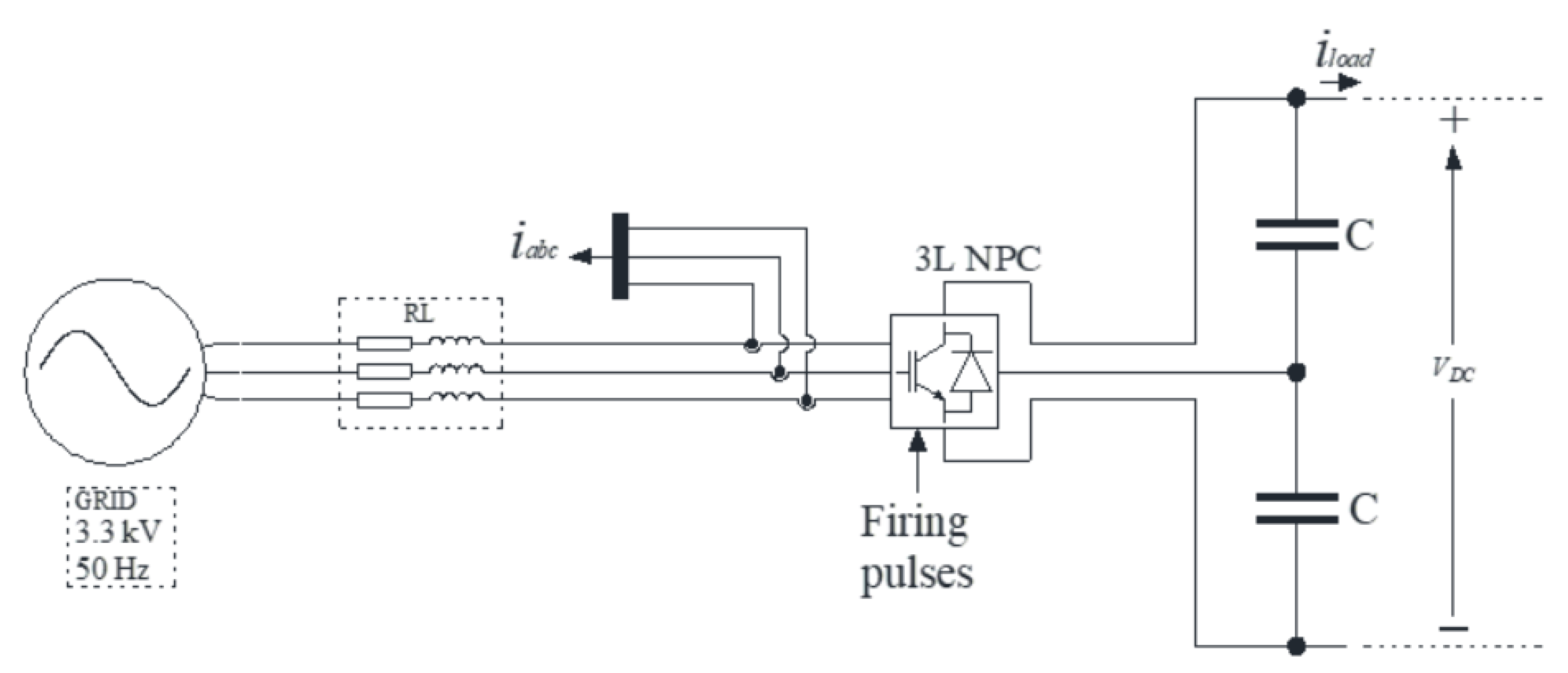
The designed system is presented in Figure 2. The system consists of a three-level three-phase active front end connected to the three-phase voltage source, where RL is a model of a grid and step-down transformer impedance, C is the DC link capacitors and i l o a d is the DC link current (load current). The active front end is based on five switching states in the first quarter of the fundamental harmonic period.
The desired system requirements from Figure 2 are stated as complete elimination of the 5th and the 7th harmonics, with minimization of the 29th, the 31st, the 35th and the 37th harmonics. An additional constraint is that the difference between the two switching angles for a given modulation index (m) is large enough to obey the minimum on/off switching time. These requirements can be expressed as an optimization problem as
min : | V 29 th | + | V 31 th | + | V 35 th | + | V 37 th | subject   to { cos ( θ 1 ) cos ( θ 2 ) + cos ( θ 3 ) cos ( θ 4 ) + cos ( θ 5 ) m π 4 = 0 cos ( 5 θ 1 ) cos ( 5 θ 2 ) + cos ( 5 θ 3 ) cos ( 5 θ 4 ) + cos ( 5 θ 5 ) = 0 cos ( 7 θ 1 ) cos ( 7 θ 2 ) + cos ( 7 θ 3 ) cos ( 7 θ 4 ) + cos ( 7 θ 5 ) = 0 0 < θ 1 < θ 2 < θ 3 < θ 4 < θ 5 < π 2 . θ 2 θ 1 minimumon / offtime θ 3 θ 2 minimumon / offtime θ 4 θ 3 minimumon / offtime θ 5 θ 4 minimumon / offtime

3. Brute Force Method

3.1. Algorithm for the Brute Force Method

The BF search method is explained and demonstrated in this chapter on a particular example of a system described in Figure 2. However, this does not exclude the application of the proposed method to other systems or different constraints on higher-order harmonics contents. With elimination of only the 5th and the 7th harmonics, an additional degree of freedom is created for minimization of the 29th, the 31st, the 35th and the 37th harmonics which are defined with the L 1 norm. The problem of elimination of the 5th and the 7th harmonics has an infinite number of solutions (for the given modulation index (m)), wherein each of these solutions gives the desired first harmonic and elimination of the 5th and the 7th, but has a different L1 norm of the 29th, the 31st, the 35th and the 37th harmonics.
The method starts by finding as many possible solutions for the given modulation index (m), where each of these solutions will give the desired first harmonic and elimination of the 5th and the 7th. These solutions are obtained by solving
cos ( θ 1 ) cos ( θ 2 ) + cos ( θ 3 ) cos ( θ 4 ) + cos ( θ 5 ) m π 4 = 0 cos ( 5 θ 1 ) cos ( 5 θ 2 ) + cos ( 5 θ 3 ) cos ( 5 θ 4 ) + cos ( 5 θ 5 ) = 0 cos ( 7 θ 1 ) cos ( 7 θ 2 ) + cos ( 7 θ 3 ) cos ( 7 θ 4 ) + cos ( 7 θ 5 ) = 0 ,
with the NR method by changing the initial solutions. When a sufficient number of solutions is acquired, the solution that has the lowest L1 norm of a higher-order harmonic (the 29th, the 31st, the 35th and the 37th) which obeys the minimum on/off switching time is chosen (feasible solution). This chosen solution represents the starting point for the BF method, and it is a five-dimensional vector described in general form as
θ i = [ θ 1 θ 2 θ 3 θ 4 θ 5 ] ,
where index i represents the i-th solution of the BF method. The system of equations defined with Equation (9) can be written as
C ( θ ) = [ c 1 ( θ ) c 5 ( θ ) c 7 ( θ ) ] = [ cos ( θ 1 ) cos ( θ 2 ) + cos ( θ 3 ) cos ( θ 4 ) + cos ( θ 5 ) m π 4 cos ( 5 θ 1 ) cos ( 5 θ 2 ) + cos ( 5 θ 3 ) cos ( 5 θ 4 ) + cos ( 5 θ 5 ) cos ( 7 θ 1 ) cos ( 7 θ 2 ) + cos ( 7 θ 3 ) cos ( 7 θ 4 ) + cos ( 7 θ 5 ) ] ,
where C ( θ ) is the vector valued function. The solution for the given modulation index (m) should satisfy the vector valued function in the Equation (11) as
C ( θ i ) = 0 .
The basic concept of the BF method is to search the feasible solution space around the solution θ i in order to obtain the set of solutions (firing angles), where each of the obtained solutions will satisfy the vector valued function defined with Equation (12). The search of a feasible solution space around the solution θ i is done by linearization of the vector valued function defined in Equation (11) by developing it in Taylor series up to the first order as
C ( θ i + δ θ ) C ( θ i ) + J ( θ i ) δ θ ,
where δ θ is a vector of small change in the vicinity of solution θ i and J ( θ i ) is a Jacobian matrix of the vector valued function C ( θ i ) in the i-th solution defined as
J ( θ i ) = [ c 1 ( θ i ) θ 1 c 1 ( θ i ) θ 2 c 1 ( θ i ) θ 3 c 1 ( θ i ) θ 4 c 1 ( θ i ) θ 5 c 5 ( θ i ) θ 1 c 5 ( θ i ) θ 2 c 5 ( θ i ) θ 3 c 5 ( θ i ) θ 4 c 5 ( θ i ) θ 5 c 7 ( θ i ) θ 1 c 7 ( θ i ) θ 2 c 7 ( θ i ) θ 3 c 7 ( θ i ) θ 4 c 7 ( θ i ) θ 5 ] ,
Vector δ θ which represents the small change in the five-dimensional space around solution θ i is defined as
δ θ = [ δ θ 1 δ θ 2 δ θ 3 δ θ 4 δ θ 5 ] T .
Linear approximation of the vector valued function C ( θ i ) defined with Equation (13) is only accurate in the vicinity of solution θ i . To ensure that linear approximation remains accurate, the direction of small change needs to be calculated in such a way that the value of the first harmonic maintains the desired value, and that the fifth and the seventh harmonics remain eliminated. From a theoretical point of view, this can be expressed as
J ( θ i ) δ θ = 0 .
Therefore, in order to determine the direction in which the linear approximation will be sufficiently accurate, it is necessary to solve the homogeneous linear system of equations described with Equation (16) for the unknown vector δ θ , where δ θ should be a non-zero vector. Clearly, solving this homogeneous linear system of equations described with Equation (16) results in a vector (or vectors) which defines the direction where the method can search without disturbing the desired first harmonic or elimination of the fifth and the seventh harmonics. This statement can be expressed as
C ( θ i + δ θ ) = C ( θ i ) + J ( θ i ) δ θ = 0 .
The homogeneous linear system of equations described with Equation (16) cannot be solved by inverting the Jacobian matrix, because it is not a square one. Further, solving this problem by determining the pseudo inverse of the system is not desirable, because this approach would result in only one solution. The answer to this problem lies in searching the null space of the Jacobian matrix as
N ( θ i ) = N u l l ( J ( θ i ) ) ,
The term N ( θ i ) in Equation (18) denotes a matrix whose columns are vectors that span the null space (solution space) of the Jacobian matrix. Since the Jacobian matrix has five columns and three rows, it follows that the null space matrix will have two columns. These two columns are two vectors that describe the null space of the Jacobian matrix. The null space matrix is defined as
N ( θ i ) = [ v 1 ( θ i )   v 2 ( θ i ) ] ,
where v 1 ( θ i ) and v 2 ( θ i ) are vectors of the null space matrix, whose any linear combination will satisfy Equation (16) as
J ( θ i ) δ θ = J ( θ i ) ( α   ·   v 1 ( θ i ) + β   ·   v 2 ( θ i ) ) = 0 ,
where α and β are real value numbers which define the direction of the search. The search direction where the first harmonic will maintain the desired value, and the fifth and the seventh harmonics will be eliminated is now defined with only two vectors, v 1 ( θ i ) and v 2 ( θ i ) . Vector δ θ , which represents the small change, can now be defined as
δ θ = α   ×   v 1 ( θ i ) + β   ×   v 2 ( θ i ) ,
and a new solution, or more precisely a new point in the five-dimensional space, can be defined as
θ i + 1 = θ i + δ θ .
Movement to the new point in the feasible solution space causes a certain error because of the linear function approximation of C ( θ i ) . This new point described with Equation (22) now applies
C ( θ i + 1 ) 0 ,
Cleary, the smaller the value of α and β , the smaller the error will be at the end. For this reason, error compensation is added to reduce the error caused by linear approximation. Movement to the new point with error compensation is defined as
θ i + 1 = θ i + δ θ + δ θ c ,
where δ θ c is a vector for error compensation. The calculation of error compensation vector δ θ c is based on the linear approximation of vector valued function C ( θ ) at point θ i + 1 as
C ( θ i + 1 ) = C ( θ i + 1 ) + J ( θ i + 1 ) δ θ ,
which assumes that the error compensation vector δ θ c is sufficiently small. Error compensation vector δ θ c is calculated by equalizing the right side of Equation (25) with the zero vector as
C ( θ i + 1 ) + J ( θ i + 1 ) δ θ = 0 .
The problem described with Equation (26) has no unique solution, since the Jacobian is not a square matrix and has no inverse. Furthermore, Equation (26) has an infinite number of solutions where some of these solutions could bring the method back to the starting point. The problem stated with Equation (26) is solved using a pseudo inverse of the system, which will provide the solution (vector) with the smallest possible length. The pseudo inverse of the system defined with Equation (26) is given as
δ θ c = J ( θ i + 1 ) T ( J ( θ i + 1 ) J ( θ i + 1 ) T ) 1 C ( θ i + 1 ) .
With the calculation of the error compensation vector δ θ c , the method can now determine the new point of the solution according to Equation (24). By doing this, the method moves from the starting point θ i to a new point θ i + 1 without disturbing the desired first harmonic or elimination of the fifth and the seventh harmonics. Since the movement from one point to another is small enough, the constraints on the minimum on/off switching time are obeyed.

3.2. Search Direction of the Brute Force Method

Section 3.1 described the basic concept of the devised BF, i.e., described how the method moves from one feasible solution point to another. The BF method is a global optimization method. Therefore, it requires additional information in which the direction it should go to satisfies the defined constraints. The direction of the search is determined by the solution of Equation (12), which represents a starting point for the BF method in five-dimensional space, from where the method starts to move in radial directions. These initial directions from the starting point are described as
Initial   Directions = cos ( φ )   ×   v 1 ( θ i ) + sin ( φ )   ×   v 2 ( θ i ) ,   for   i = 0 ,
where φ represents the angle uniformly distributed in the interval from 0 to 2π. The cos ( φ ) and sin ( φ ) in Equation (28) are now actually α and β from Equation (20) and they define the radial search direction.
The proposed algorithm after finding the solution points in radial directions from the starting point goes further from each of the radially distributed points. This radial search is presented in simplified form in Figure 3 (in this example, in reality, it should be represented by a five-dimensional figure), where θ 0 represents the starting point for the BF method for the given modulation index (m).
The general expression for determining the radial searching directions for the i-th solution is given as
δ θ i = ( δ θ 0 ) T v 1 ( θ i ) ( v 1 ( θ i ) ) T v 1 ( θ i ) v 1 ( θ i ) + ( δ θ 0 ) T v 2 ( θ i ) ( v 2 ( θ i ) ) T v 2 ( θ i ) v 2 ( θ i ) ,
The goal for determining the searching directions is to keep it as much as possible in the direction of the initial direction described with Equation (28).
A stop criterion for the brute force method is when a maximum number of solutions is obtained. The BF method, during a radial search, automatically stops the search in one of the directions if the solution in that direction violates the minimum on/off switching time or if the solution deviates a lot from the solution of the previous modulation index (m). Criteria that stop the search in one of the radial directions if the solution deviates a lot are necessary to ensure the continuity of pulse patterns. The BF method, after reaching the maximum number of solutions, gives a solution at the end of the process with the lowest L 1 norm. The given solution is a final solution for the given modulation index which gives a desired first harmonic and elimination of the 5th and the 7th harmonics. This given solution has the lowest L 1 norm (the 29th, the 31st, the 35th and the 37th harmonics), obeys a minimum on/off switching time and ensures the continuity of pulse patterns. After finding the best solution for the given modulation index (m), the process is repeated for a different value of the modulation index (m).
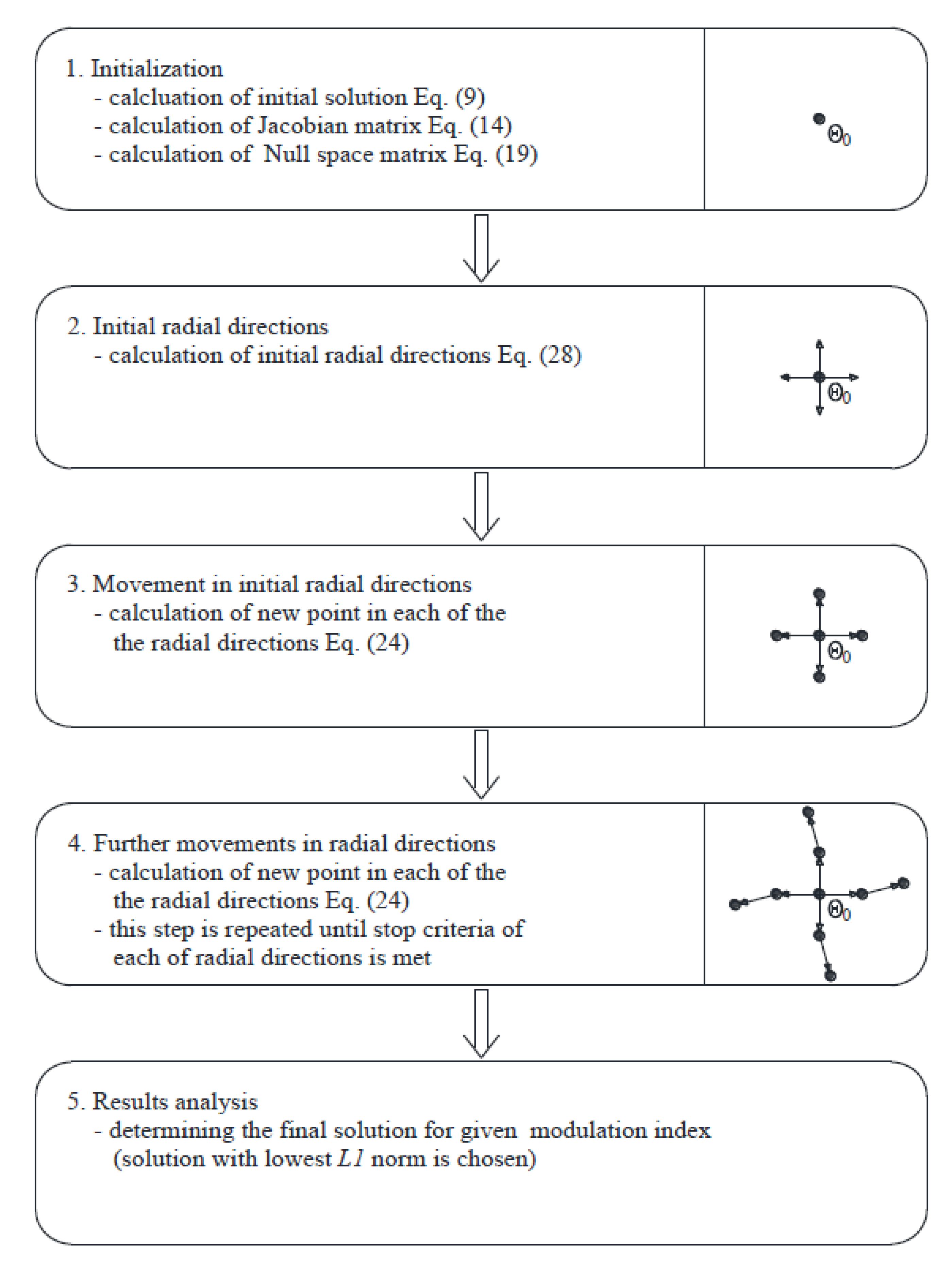
Figure 4 shows the flowchart of the BF method. The first step of the BF method is initialization, in which the method calculates the initial solution θ 0 with the NR method for the given modulation index (m). This initial solution is the solution of Equation (9) which satisfies all the additional constraints (angles are in specified order and minimum on/off switching time is obeyed). After the initial solution is found, the method calculates the Jacobian matrix (Equation (14)) and null space of the Jacobian matrix (Equation (19)). The second step of the BF method is calculation of the initial radial direction (Equation (28)), in which the method will begin to search the feasible solutions. In the third step, the method moves in the radial directions and determines the new solutions. The method in the fourth step searches further in radial directions for new solutions, and this step is repeated until one of the stopping criteria is met. In the fifth step, all the determined solutions are analyzed, and the optimal solution is chosen (solution with the lowest L 1 norm).

4. Obtained Results with the Brute Force Method

4.1. Determined Pulse Patterns and Comparison with Other Methods

The BF method described in Section 3 is implemented in GNU Octave. The calculation of the pulse patterns is done for the modulation index (m) in the interval 0.6 ,   1.14 with the resolution of 5   ×   10 4 . The minimum on/off switching time is set to 100   μ s , which corresponds to the 0.0314 rad for 50 Hz frequency of the fundamental harmonic. The maximum deviation of the switching angles between two neighboring modulation indexes (m) is set to 0.04 rad to ensure the continuity of pulse patterns. The BF method starts the search in 100 radial directions from the initial solution, where the maximum number of solutions is set to 10,000. The calculation is conducted for the grid voltage of 3.3 kV (line to line RMS value). To demonstrate the effectiveness of the BF method, the authors also present results for an optimization problem defined with Equation (8) obtained with the NR method and particle swarm optimization (PSO) method. Results obtained with the NR method are actually initial solutions for the BF method as stated in Section 3, i.e., they represent the starting point for the BF method from where the method starts to search for more optimal solutions considering the defined L 1 norm. The PSO method based on swarm intelligent algorithms is an optimization tool for unconstrained optimization problems. Due to this, constraints defined in the optimization problem in Equation (8) are added to the cost function in the form of penalty functions. The PSO method is initialized with a population number of 100 particles with the maximum number of iterations set to 400. Constraints regarding the minimum on/off switching time and maximum deviation of the switching angles between two neighboring modulation indexes (m) are the same as for the BF method.
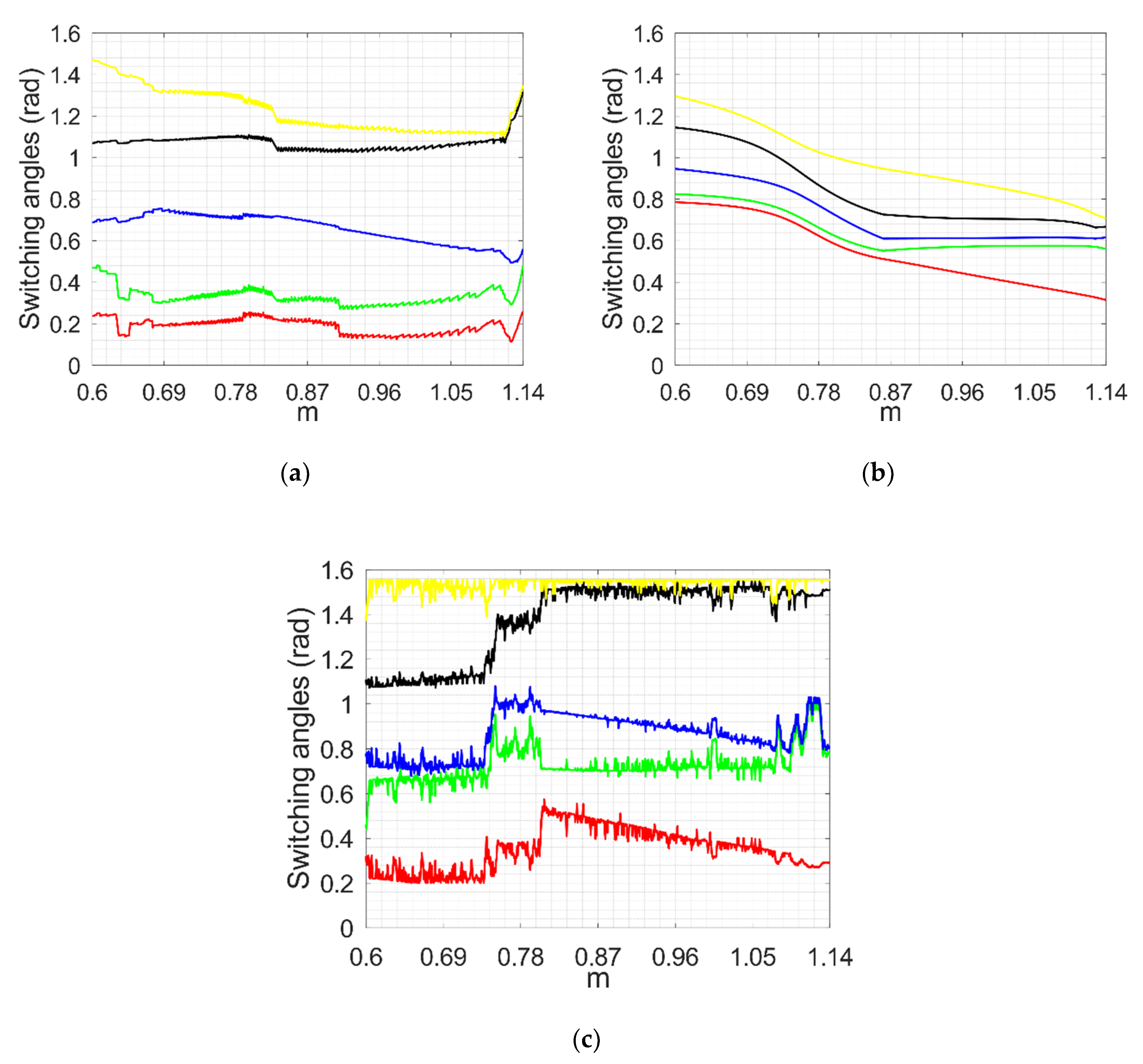
Figure 5 shows pulse patterns obtained with the BF method (Figure 5a), NR method (Figure 5b) and PSO method (Figure 5c). By comparing pulse patterns obtained with the BF method (Figure 5a) and with the NR method (Figure 5b), a conclusion can be made that pulse patterns obtained with the BF method display more noisiness. These noisiness was expected because the BF method presented in this paper also minimizes higher-order harmonics (the 29th, the 31st, the 35th and the 37th harmonics) in regard to the NR method which only deals with elimination of low-order harmonics (the fifth and the seventh harmonics). A comparison can also be made between pulse patterns obtained with the BF method (Figure 5a) and PSO method (Figure 5c). By comparing these two pulse patterns (Figure 5a,c), the conclusion can be made that the BF method provides more continuous (less noisiness) pulse patterns and that the on/off switching time is much higher for the whole range of the modulation index (m) than for the pulse patterns obtained with the PSO method.
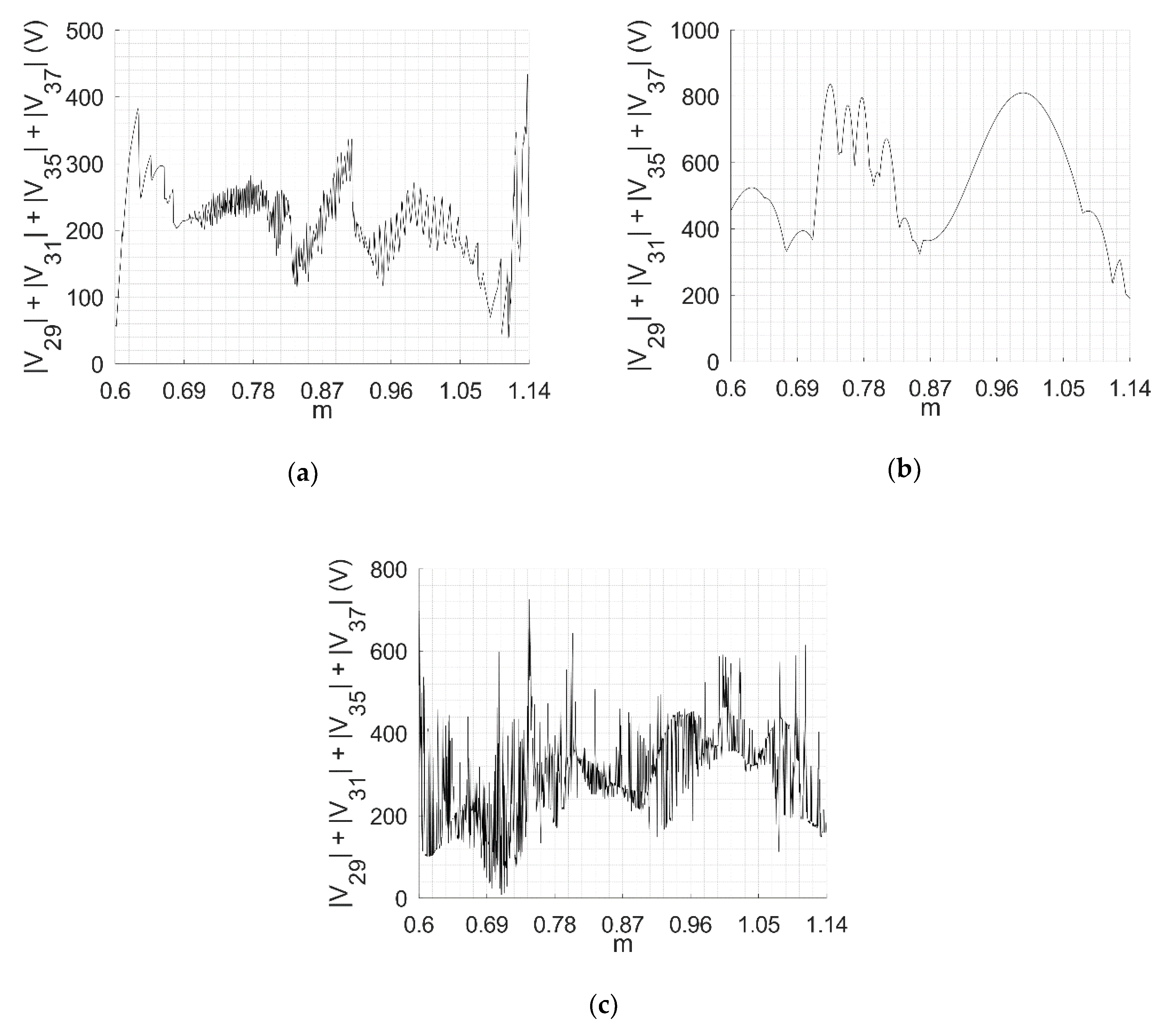
Figure 6 shows the calculated L 1 norms for the BF method (Figure 6a), NR method (Figure 6b) and PSO method (Figure 6c). Comparing these three L 1 norms, a conclusion can be made that the NR method has the highest L 1 norm through the whole range of the modulation index (m) in regard to the BF and the PSO methods. Although the L 1 norm of the BF method (Figure 6a) and the PSO method (Figure 6c) seems to be similar, calculating the average value of L 1 norms of both methods reveals that the average value of the L 1 norm of the BF method is 214.26 V, and the average value of the L 1 norm of the PSO method is 298.62 V (in the given range of the modulation index (m)).
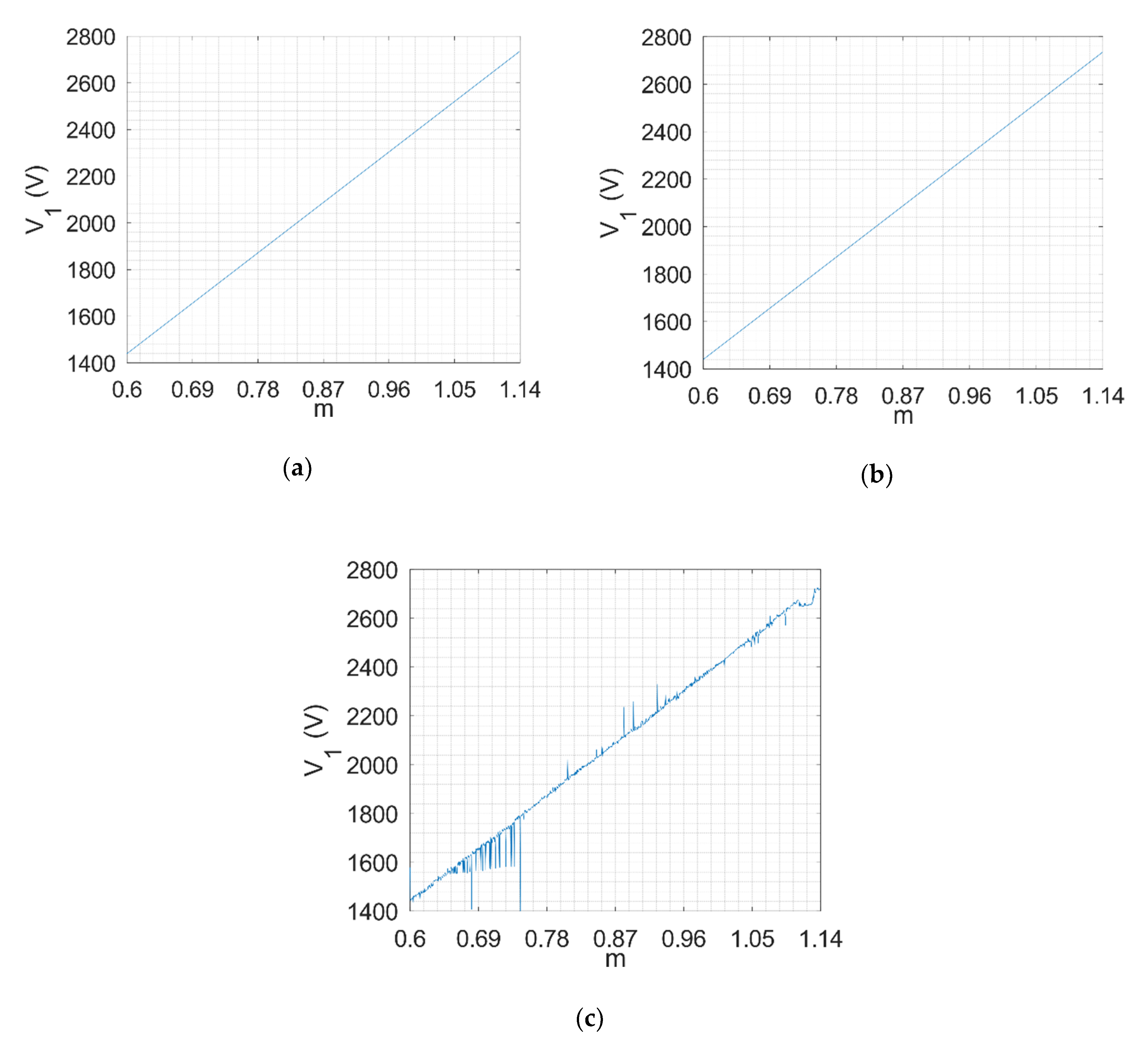
The verification of the calculated results was done by calculating the first, the fifth and the seventh harmonics with the obtained pulse patterns. Figure 7 shows the obtained first harmonic for the BF method (Figure 7a), NR method (Figure 7b) and PSO method (Figure 7c). Based on these results, it can be stated that the BF (Figure 7a) and NR (Figure 7b) methods give the desired first harmonic which has a linear dependence on the modulation index (m). The first harmonic of pulse patterns calculated with the PSO method reveals that for low and high values of the modulation index (m), the method fails to converge on the solution, which means that for some values of the modulation index (m), linear dependence on the modulation index (m) is not met. To resolve this problem of convergence with the PSO method, the authors increased the population size of particles and maximum number of iterations, but this did not significantly improve the results.
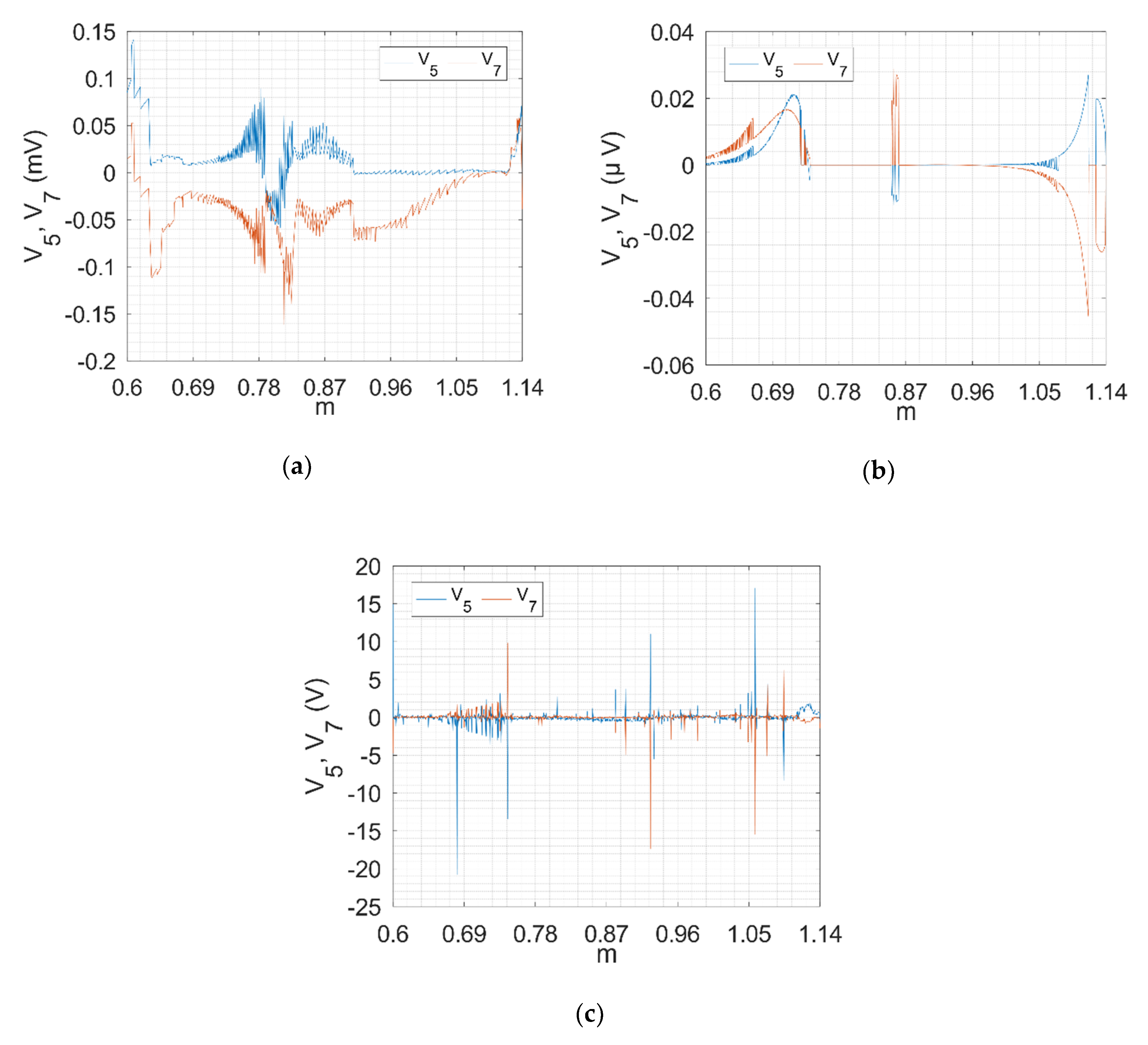
Figure 8 shows the fifth and the seventh harmonics obtained with the BF method (Figure 8a), NR method (Figure 8b) and PSO method (Figure 8c). Based on these figures, it can be stated that the BF and NR methods have the smallest fifth and seventh harmonics and that their values never exceed 0.17 mV. When you consider that the first harmonic has much higher amplitude, these fifth and seventh harmonics have almost no influence. The fifth and the seventh harmonics of pulse patterns calculated with the PSO method (Figure 8c) have much higher amplitude than the harmonic whose pulse patterns are obtained with the BF or NR methods. The reason for this is that the PSO method did not converge on the optimal solution for some values of the modulation index (m).
The results obtained from the BF method were presented in this subsection. For the sake of comparison, the authors also presented the results obtained with the NR and PSO methods. The presented results clearly show that the BF method, in addition to eliminating the lower-order harmonics (the fifth and the seventh), minimized the higher-order harmonics (the 29th, the 31st, the 35th and the 37th). Comparing the BF method with the NR and PSO methods, the conclusion can be made that all three methods have successfully eliminated the fifth and the seventh harmonics. However, the BF method has much better suppression of higher-order harmonics (the 29th, the 31st, the 35th and the 37th) while simultaneously obeying additional constraints on the minimum on/off switching time and continuity of pulse patterns. This additional feature of the BF method of the minimization of selected higher-order harmonics with simultaneous elimination of lower-order harmonics is a key advantage of the proposed method because SHE-PWM has only a limited number of harmonics that can be eliminated.

4.2. Simulation of 3LV NPC AFE with SHE-PWM in Closed Loop with Determined Pulse Patterns

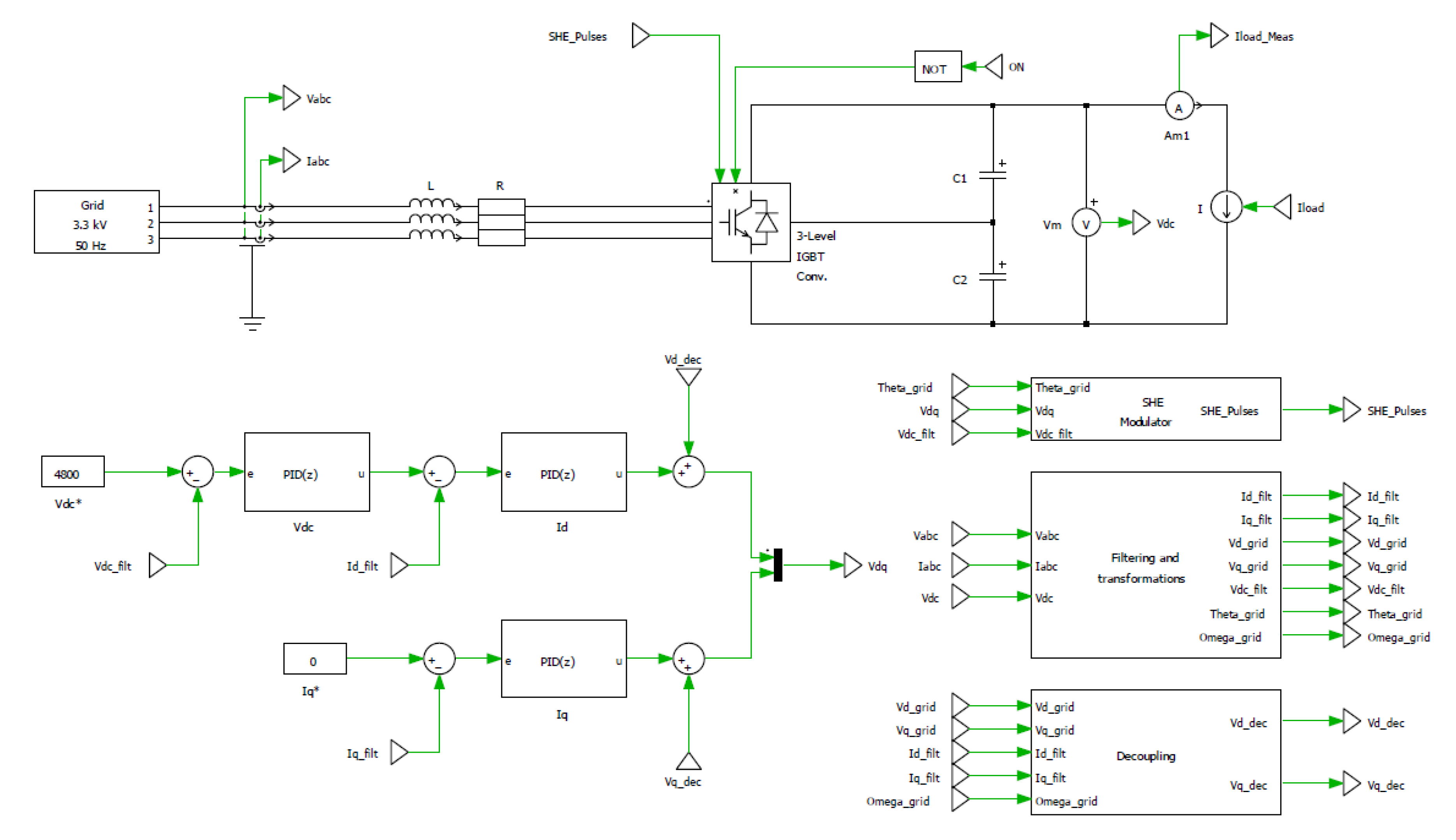
A dynamic simulation of the proposed system configuration in Figure 2 was conducted in the simulation tool PLECS to verify the pulse patterns calculated with the BF method. The control structure for the SHE-PWM in a closed loop was used for controlling the DC link voltage as it is described in the literature [2,22,23]. Figure 9 illustrates the simulation schematic in the simulation tool PLECS.
The simulation schematic in Figure 9 consists of two parts, namely the power part and the control part. The power part consists of the 3 LV NPC AFE and corresponding DC link. The DC link is constructed from two capacitors and a current source for load simulation. The AC side of the 3 LV NPC AFE is connected to the grid power supply through grid impedance LR. The control part consists of an internal current and an external voltage loop. The internal current loop consists of two current PI regulators for regulating the currents in the d-q rotating reference frame synchronous with the grid voltage. The external voltage loop is a PI regulator for regulation of the DC link voltage. PI regulators are tuned by a trial and error method and by authors’ experience. Signals V d _ d e c and V q _ d e c are decoupling signals between the d and q axes. The SHE Modulator block in Figure 8, based on voltages on the direct and quadrature axes and DC link voltage, calculates firing pulses for the 3 LV NPC AFE converter. Calculation of firing pulses is based on pulse patterns calculated with the BF method presented in Section 3. Block Filtering and transformations filters the measured values (grid voltage and current and DC link voltage) and transforms the grid voltage and currents into a d-q rotating reference frame. Block Decoupling calculates the decoupling signals based on the grid impedance.
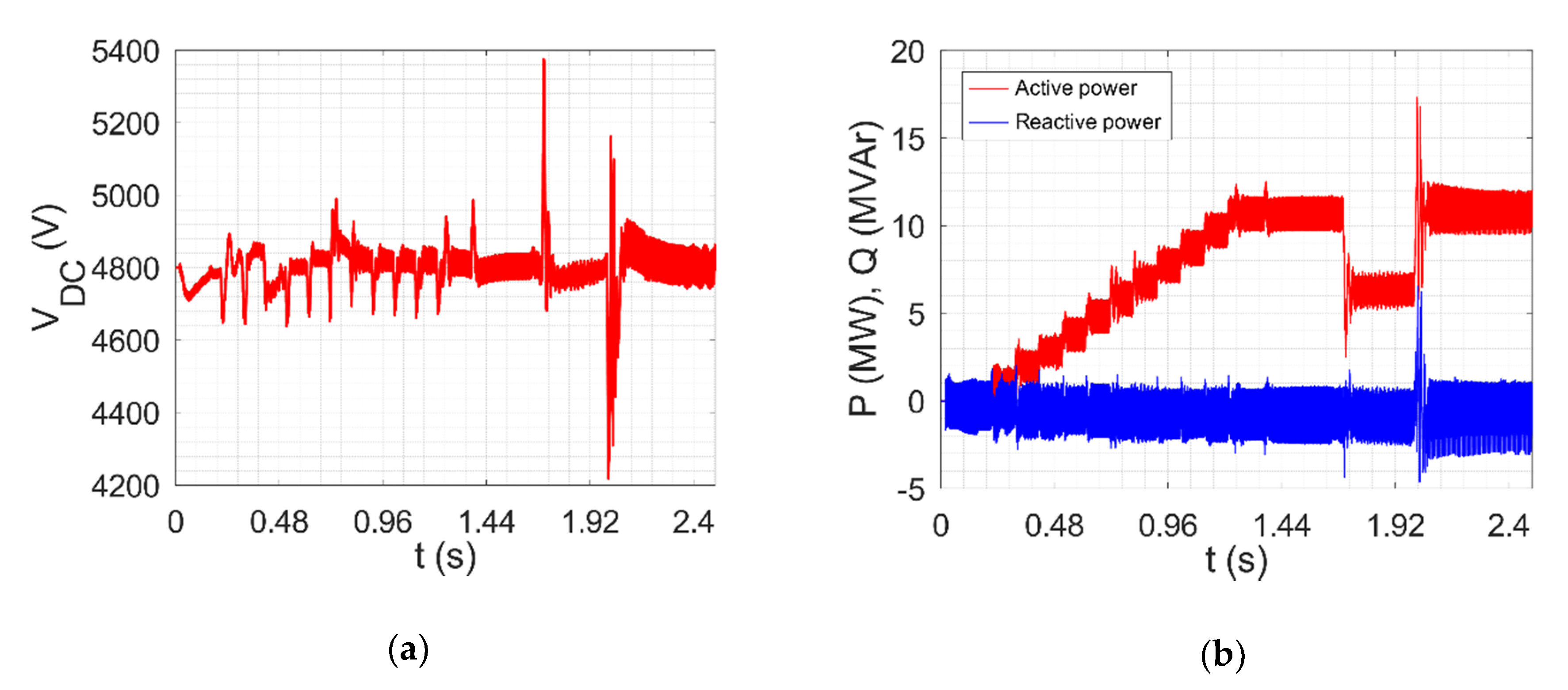
The simulation starts with the 3 LV NPC AFE in no load condition and then the load is gradually increased to the rated load. In the simulation time of 1.7 s, the load is reduced by 40% of the rated power and then in the simulation time of 2 s is increased back to 100% of the rated power. The load is simulated with the current source. Figure 10a shows a dynamic response of the DC link voltage, and Figure 10b shows active and reactive power. Simulation results clearly show that with the determined pulse patterns, the simulated system is stable during transients and in steady state, even if the load is suddenly reduced by 40% and then increased suddenly back to 100% of the rated power.
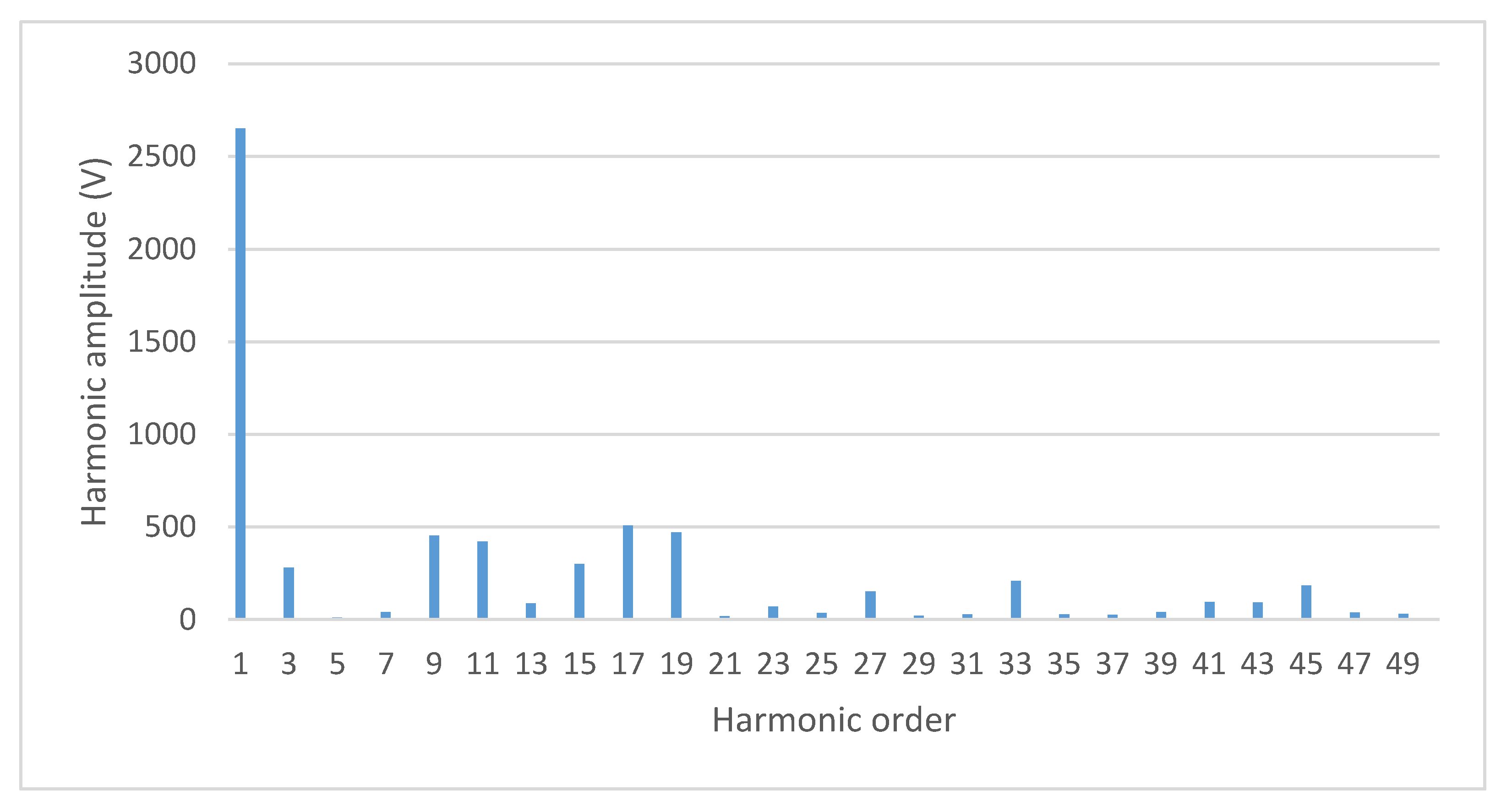
Figure 11 shows a specter of line to neutral voltage for a modulation index equal to 1.085, from which it is clearly visible that the fifth and the seventh harmonics are eliminated. Moreover, the higher-order harmonics (the 29th, the 31st, the 35th and the 37th) have very low amplitude, which means that the proposed BF method has fulfilled its task of minimizing them.

4.3. Experimental Results for 3 LV NPC AFE with SHE-PWM in Closed Loop with Determined Pulse Patterns

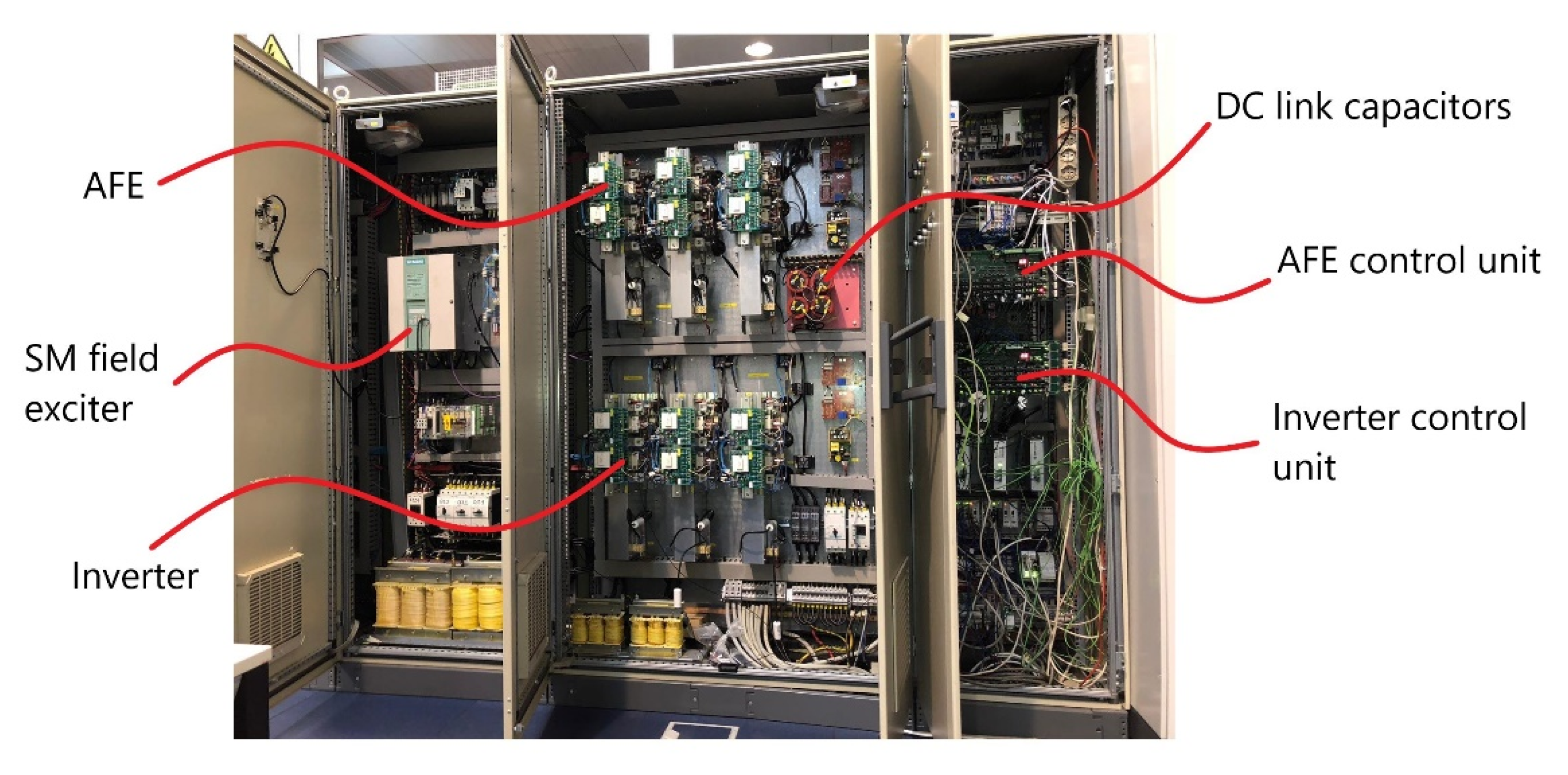
Verification of pulse patterns obtained with the BF method was done on a low-voltage 3 LV NPC AFE converter. The modulation technique for the 3 LV NPC AFE converter is SHE-PWM based on five switching states in the first quarter of the fundamental harmonic. The rated power of the 3 LV NPC AFE converter is 55.4 kVA (Appendix B) and it is connected to the 400 V, 50 Hz grid. The DC link consists of two capacitors as in Figure 2, and it is connected to the inverter. The inverter modulation technique is space vector PWM with a switching frequency of 1.25 kHz. The inverter is connected to the synchronous motor (SM) of 18.5 kW of rated power. The shaft of the SM is connected to the DC motor to generate load torque. The experimental system is shown in Figure 12.
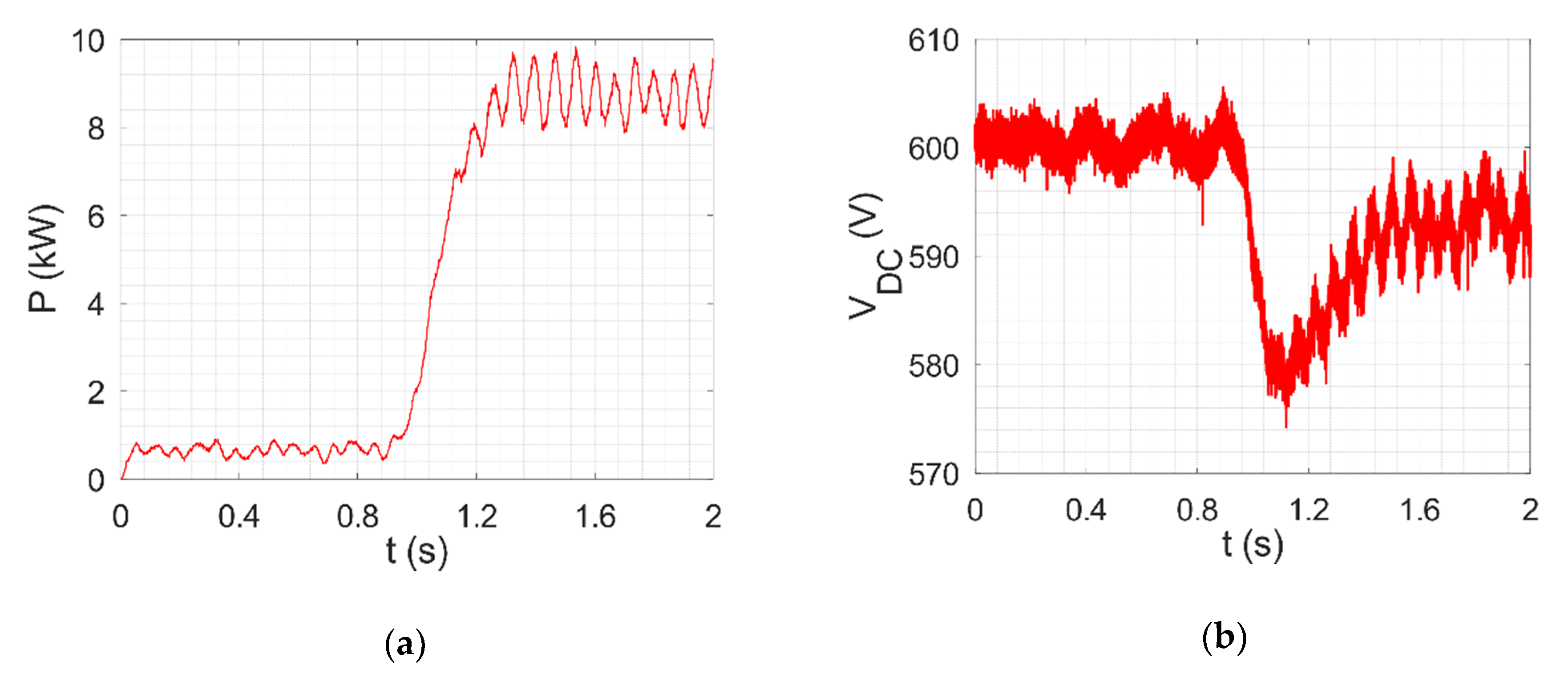
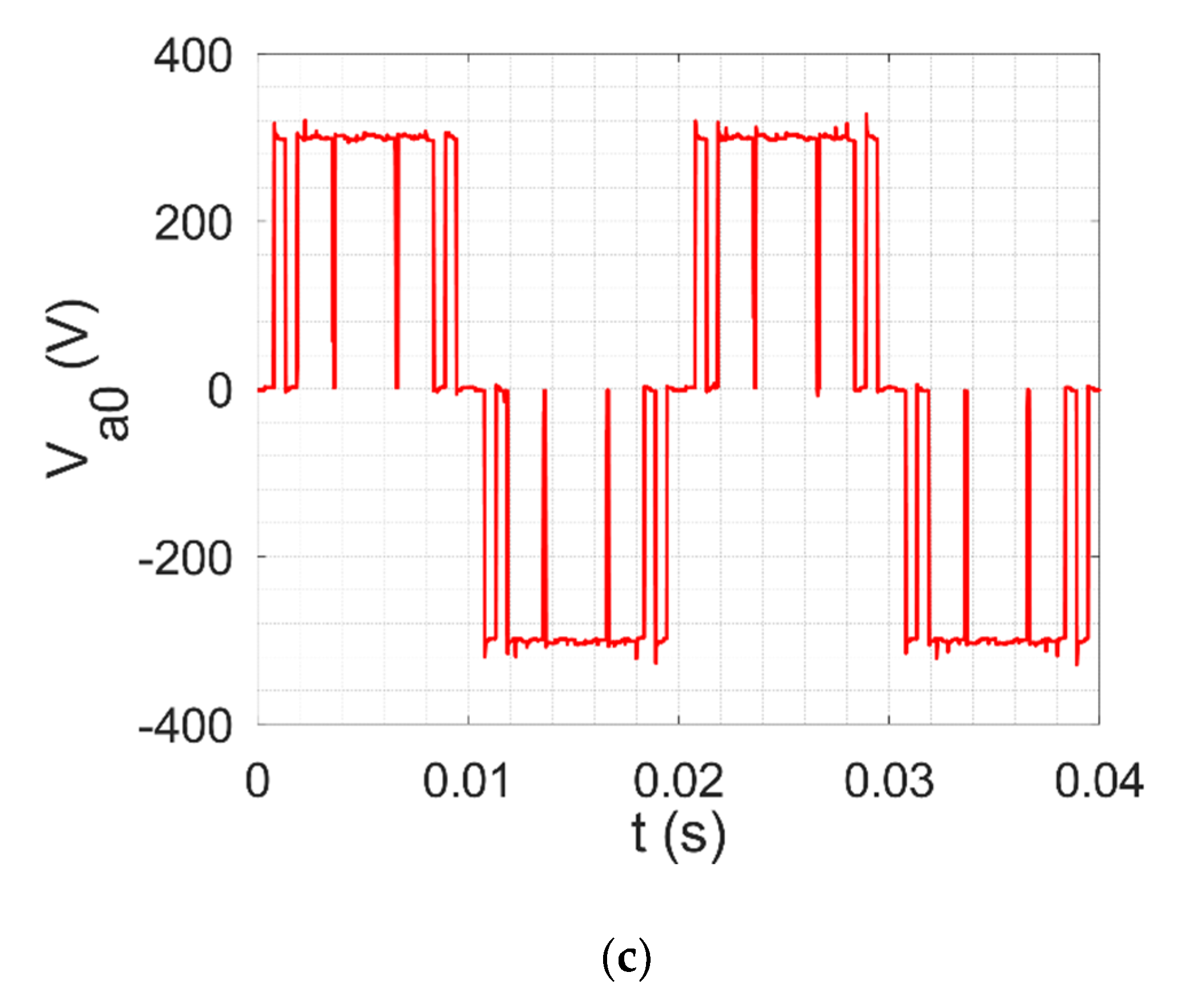
The experiment for the verification of the calculated pulse patterns was done for the case when the SM runs in no load condition with the rated speed (900 rpm), and then suddenly the load torque is increased to 50% of the rated load. Figure 13a shows the measured active power of the 3 LV NPC AFE converter during the experiment, where the active power is suddenly increased from 500 W to 8.5 kW. The DC link voltage during this experiment is shown in Figure 13b, from where it is clear that the voltage in the DC link drops only about 7 V after transient. The voltage of the 3 LV NPC AFE converter after motor torque is suddenly increased, as shown in Figure 13c. The presented measurements clearly show that the 3 LV NPC AFE converter with the calculated patterns can work in closed loop, i.e., the system remains stable after a high dynamic response.
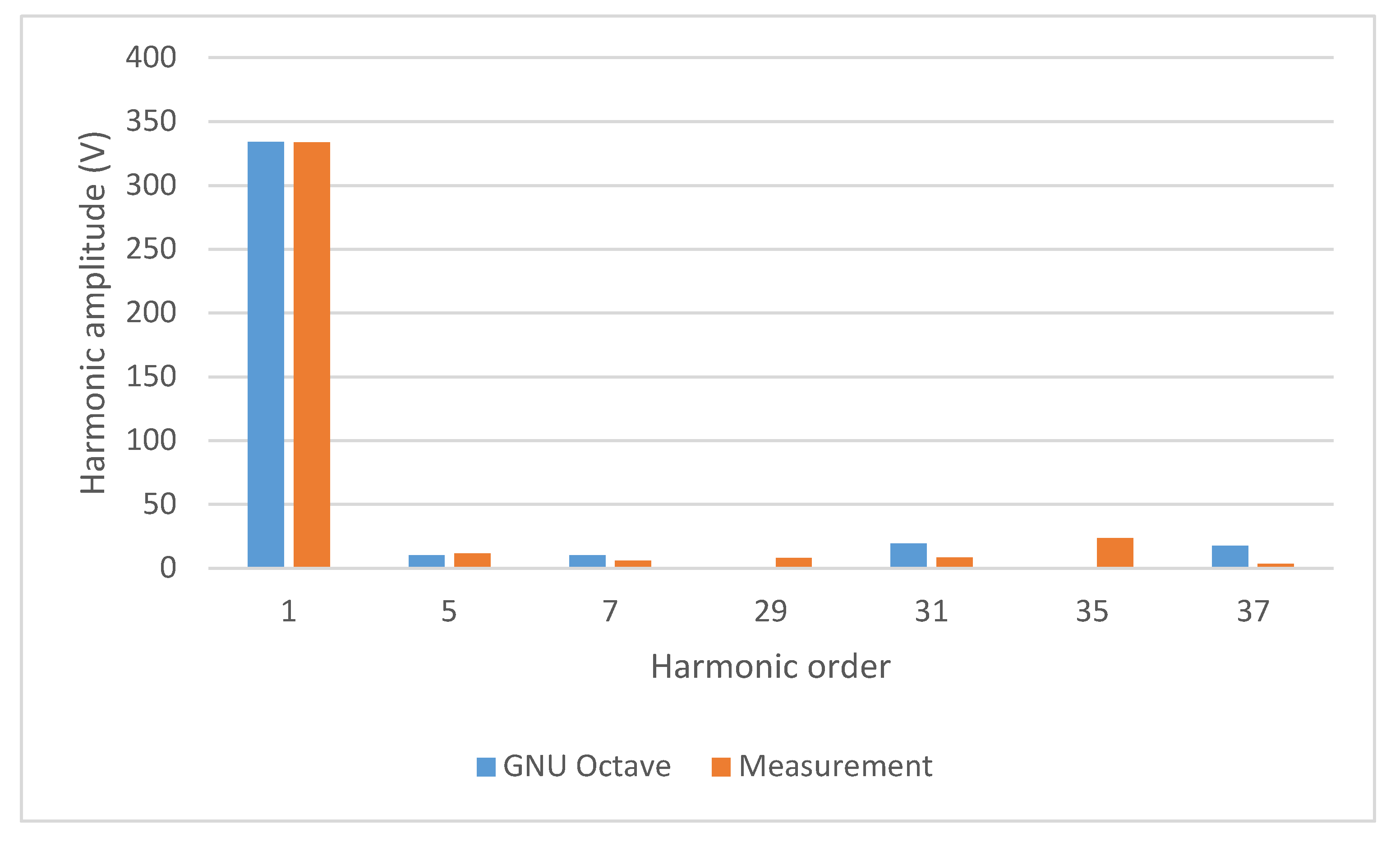
The final verification of the proposed BF method was done by calculating the voltage specter of the 3 LV NPC AFE converter. The voltage specter is calculated for the voltage after the SM load is suddenly increased which corresponds to the modulation index (m) of 0.875. The specter was calculated for the 1st, the 5th, the 7th, the 29th, the 31st, the 35th and the 37th harmonics and it is compared with the specter calculated from pulse patterns obtained with the BF method in GNU Octave. These voltage specters are shown in Figure 14. Results clearly shows that the measured amplitude of the first harmonic is approximately the same as the amplitude of the first harmonic in the simulation (error is below 1%). The biggest deviations from the simulations results are for the 29th and the 35th harmonics. These deviations can be attributed to the dead time, which the BF method does not consider. Based on Figure 14, the conclusion can be made that the experimental results verify the presented BF method as a reliable technique for determining the pulse patterns which will provide the elimination of low-order harmonics and minimization of selected higher-order harmonics.

5. Conclusions

This paper presents a new approach for determining the pulse patterns for SHE-PWM on a 3 LV NPC AFE converter. The presented method is based on a BF algorithm and demonstrated on an SHE-PWM with five switching states in the first quarter of the fundamental harmonic. Since SHE-PWM has a limited number of harmonics that can be eliminated, in this paper, a BF method is presented for calculation of pulse patterns that can, in addition to eliminating the lower-order harmonics, minimize (suppress) the selected higher-order harmonics. The BF method also considers the additional constraints on the pulse patterns as the minimum on/off switching time and continuity of pulse patterns.
The BF method in this paper is compared to the other methods, such as the NR and PSO methods. Based on this comparison, the BF method can minimize the selected higher-order harmonics more efficiently and simultaneously ensure that constraints on the minimum on/off switching time and continuity of pulse patterns are obeyed. Due to this, the BF method presented in this paper is a reliable technique for determining the pulse patterns for SHE-PWM.
The calculated pulse patterns were implemented in a laboratory setup of a low-voltage 3 LV NPC AFE converter, and tested during a high dynamic response. From the presented results, the obtained pulse patters provide a stable system during a high dynamic response without overcurrent and overvoltage trips. This paper also presents a specter of the 3 LV NPC AFE voltage for the verification of the BF method. Based on this specter, the main conclusion is that the BF method has fulfilled all the constraints on the pulse patterns defined in this paper, i.e., elimination of the 5th and the 7th harmonics, and minimization of higher-order harmonics (the 29th, the 31st, the 35th and the 37th).
The next step of this research will be the implementation of the obtained pulse patterns in a medium-voltage 3 LV NPC AFE converter.

Author Contributions

Conceptualization, D.C. and N.T.; methodology, N.T.; software, S.B.; validation, D.C. and N.T.; formal analysis, D.C. and N.T.; investigation, N.T.; resources, N.B.; data curation, N.B. and S.B.; writing—original draft preparation, D.C.; writing—review and editing, D.C., N.T. and N.B.; visualization, D.C. and N.T.; supervision, N.B.; project administration, N.B.; funding acquisition, N.B. and S.B. All authors have read and agreed to the published version of the manuscript.

Funding

This research was funded in part by University of Rijeka under the project uniri-tehnic-18-74 1207 and University of Rijeka (Faculty of Engineering) under the project Advanced Control Structures For Electrical Drives.

Acknowledgments

The authors would like to thank the Danieli Automation SpA (Italy) company for the support.

Conflicts of Interest

The authors declare no conflict of interest.

Appendix A

Table A1. List of symbols used in this paper.
SymbolDescriptionFirst Mentioned in
θ k k-th switching angle for SHE-PWMEquation (2)
HHighest harmonic order that can be eliminated with SHE-PWMEquation (4)
mModulation indexEquation (5)
θ i i-th solution of the brute force methodEquation (10)
δ θ Small change in the five-dimensional space around solution θ i Equation (13)
N u l l   (   ) Matrix operatorEquation (18)
α , β Sine and cosine of search direction angleEquation (20)
δ θ c Error compensation vector. Used for error compensation caused by linear approximation.Equation (24)
φ Search direction angle. Defines initial radial search directions.Equation (28)

Appendix B

Table A2. Ratings of the three-level neutral point clamped converter with an active front end (3 LV NPC AFE) + INVERTER.
ParameterValueUnit
Rated current of 3 LV NPC AFE and INVERTER80A
Rated apparent power of 3 LV NPC AFE and INVERTER55.4kVA
Rated input voltage3 × 400V
Rated input frequency50Hz
Max. switching frequency1.5kHz

References

  1. Ma, K.; Blaabjerg, F. The Impact of Power Switching Devices on the Thermal Performance of a 10 MW Wind Power NPC Converter. Energies 2012, 5, 2559–2577. [Google Scholar] [CrossRef] [Green Version]
  2. Luqman, M.; Yao, G.; Zhou, L.; Zhang, T.; Lamichhane, A. A Novel Hybrid Converter Proposed for Multi-MW Wind Generator for Offshore Applications. Energies 2019, 12, 4167. [Google Scholar] [CrossRef] [Green Version]
  3. He, X.; Guo, A.; Peng, X.; Zhou, Y.; Shi, Z.; Shu, Z. A Traction Three-Phase to Single-Phase Cascade Converter Substation in an Advanced Traction Power Supply System. Energies 2015, 8, 9915–9929. [Google Scholar] [CrossRef] [Green Version]
  4. Zhang, R.; Lin, F.; Yang, Z.; Cao, H.; Liu, Y. A Harmonic Resonance Suppression Strategy for a High-Speed Railway Traction Power Supply System with a SHE-PWM Four-Quadrant Converter Based on Active-Set Secondary Optimization. Energies 2017, 10, 1567. [Google Scholar] [CrossRef]
  5. Dai, B.; Zhang, M.; Guo, Y.; Zhang, X. Selective harmonic elimination PWM strategy for three-level NPC inverters under fault-tolerant operation. Int. J. Innovative Comput. Inf. Control 2019, 15, 1793–1805. [Google Scholar]
  6. Luiz, A.S.A.; Filho, B.J.C. A new design of selective harmonic elimination for adjustable speed operation of AC motors in mining industry. In Proceedings of the 2017 IEEE Applied Power Electronics Conference and Exposition (APEC), Tampa, FL, USA, 26–30 March 2017. [Google Scholar]
  7. Jalili, K.; Bernet, S. Design of LCL Filters of Active-Front-End Two-Level Voltage-Source Converters. IEEE Trans. Ind. Electron. 2009, 56, 1674–1689. [Google Scholar] [CrossRef]
  8. Beres, R.; Wang, X.; Blaabjerg, F.; Bak, C.L.; Matsumori, H.; Shimizu, T. Evaluation of core loss in magnetic materials employed in utility grid AC filters. In Proceedings of the 2017 IEEE Applied Power Electronics Conference and Exposition (APEC), Tampa, FL, USA, 26–30 March 2017. [Google Scholar]
  9. Kim, J.; Lai, J.S. A Hybrid Front-end for Multi-Generator Power System Harmonic Elimination. In Proceedings of the 2019 IEEE Energy Conversion Congress and Exposition (ECCE), Baltimore, ML, USA, 29 September–3 October 2019. [Google Scholar]
  10. Pontt, J.; Rodríguez, J.; Huerta, R. Mitigation of Noneliminated Harmonics of SHEPWM Three-Level Multipulse Three-Phase Active Front End Converters With Low Switching Frequency for Meeting Standard IEEE-519-92. IEEE Trans. Power Electron. 2014, 19, 1594–1600. [Google Scholar] [CrossRef]
  11. Ojha, A.; Chaturvedi, P.; Mittal, A.; Jain, S. Neutral Point Potential Control for Three Phase 3-level Neutral Point Clamped Active Front End Converter. Int. J. Electr. Eng. Inf. 2017, 9, 342–363. [Google Scholar] [CrossRef]
  12. Abu-Rub, H.; Holtz, J.; Rodriguez, J.; Baoming, G. Medium-Voltage Multilevel Converters–State of the Art, Challenges, and Requirements in Industrial Application. IEEE Trans. Ind. Electron. 2010, 57, 2581–2596. [Google Scholar] [CrossRef]
  13. Sahali, Y.; Fellah, M.K. Selective Harmonic Eliminated Pulse-Width Modulation Technique (SHE PWM) applied to Three-level Inverter/Converter. In Proceedings of the 2003 IEEE International Symposium on Industrial Electronics, Rio de Janeiro, Brazil, 9–11 June 2003. [Google Scholar]
  14. Pontt, J.; Rodriguez, J.; Benavides, R.; De Solminihac, R.; Müller, M. Low Switching Frequency PWM with Selective Harmonic Elimination for Three-Phase Three-Level Inverters. In Proceedings of the 10th International Power Electronics and Motion Control Conference and Exposition, Cavtat & Dubrovnik, Croatia, 9–11 September 2002. [Google Scholar]
  15. Ahmad, S.; Ganie, Z.A.; Ashraf, I.; Iqbal, A. Harmonics Minimization in 3-Level Inverter Waveform and its FPGA Realization. In Proceedings of the 2018 3rd International Innovative Applications of Computational Intelligence on Power, Energy and Controls with their Impact on Humanity (CIPECH), Ghaziabad, India, 1–2 November 2018. [Google Scholar]
  16. Al-Hitmi, M.; Ahmad, S.; Iqbal, A.; Padmanaban, S.; Ashraf, I. Selective Harmonic Elimination in a Wide Modulation Range Using Modified Newton-Raphson and Pattern Generation Methods for a Multilevel Inverter. Energies 2018, 11, 458. [Google Scholar] [CrossRef] [Green Version]
  17. Kundu, S.; Deb Burman, A.; Giri, S.A.; Mukherjee, S.; Banerjee, S. Comparative study between different optimisation techniques for finding precise switching angle for SHE-PWM of three-phase seven-level cascaded H-bridge inverter. Power Electron. IET 2018, 11, 600–609. [Google Scholar] [CrossRef]
  18. Luo, H.; Mao, C.; Wang, D.; Lu, J.; Wang, L. Fundamental modulation strategy with selective harmonic elimination for multilevel inverters. Power Electron. IET 2014, 7, 2173–2181. [Google Scholar]
  19. Sundareswaran, K.; Jayant, K.; Shanavas, T.N. Inverter Harmonic Elimination through a Colony of Continuously Exploring Ants. IEEE Trans. Power Electron. 2007, 54, 2558–2565. [Google Scholar] [CrossRef]
  20. Shirmohammadi, S.; Suh, Y. Cascaded Snubber Scheme Using Flyback Type Transformer for 10 kV IGCT Application. In Proceedings of the 2019 10th International Conference on Power Electronics and ECCE Asia (ICPE 2019–ECCE Asia), Busan, Korea, 27–31 May 2019. [Google Scholar]
  21. Filsecker, F.; Alvarez, R.; Bernet, S. Comparison of 4.5-kV Press-Pack IGBTs and IGCTs for Medium-Voltage Converters. IEEE Trans. Ind. Electron. 2013, 60, 440–449. [Google Scholar] [CrossRef]
  22. Silva, C.; Oyarzún, J. High Dynamic Control of a PWM Rectifier using Harmonic Elimination. In Proceedings of the IECON 2006–32nd Annual Conference on IEEE Industrial Electronics, Paris, France, 7–10 November 2006. [Google Scholar]
  23. Rodríguez, J.; Dixon, J.W.; Espinoza, J.R.; Pontt, J.; Lezana, P. PWM Regenerative Rectifiers: State of the Art. IEEE Trans. Ind. Electron. 2005, 52, 5–22. [Google Scholar] [CrossRef]
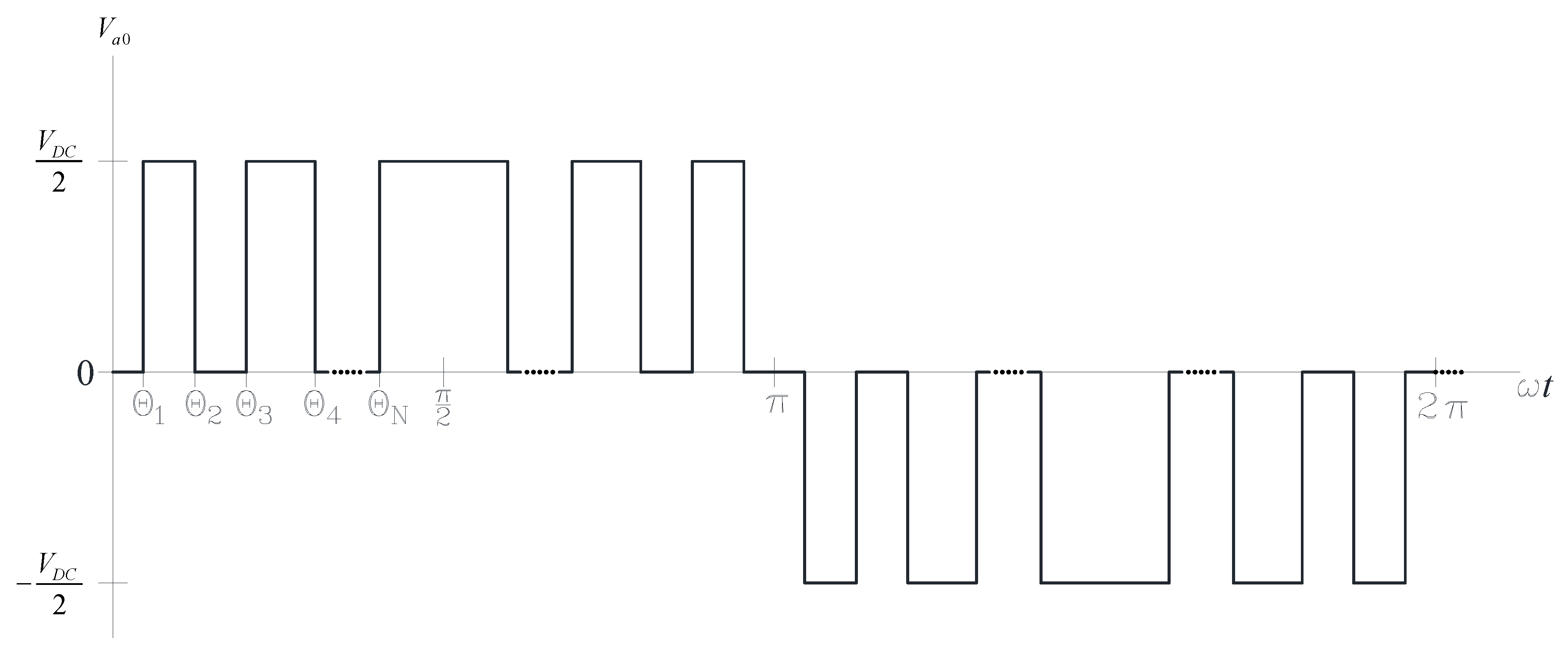
Figure 1. Three-level neutral point clamped converter with an active front end (3 LV NPC AFE) phase to neutral voltage with N switching angles.
Electronics 09 01685 g001
Figure 2. 3LV NPC AFE system.
Electronics 09 01685 g002
Figure 3. Radial searching directions.
Electronics 09 01685 g003
Figure 4. Brute force method flowchart.
Electronics 09 01685 g004
Figure 5. Pulse patterns: (a) brute force method, (b) Newton–Raphson method and (c) particle swarm method.
Electronics 09 01685 g005
Figure 6. L 1 norm: (a) brute force method, (b) Newton–Raphson method and (c) particle swarm method.
Electronics 09 01685 g006
Figure 7. The 1st harmonic: (a) brute force method, (b) Newton–Raphson method and (c) particle swarm method.
Electronics 09 01685 g007
Figure 8. The 5th and the 7th harmonics: (a) brute force method, (b) Newton–Raphson method and (c) particle swarm method.
Electronics 09 01685 g008
Figure 9. Simulation schematic of the 3LV NPC AFE in closed loop.
Electronics 09 01685 g009
Figure 10. PLECS simulation: (a) DC link voltage and (b) active and reactive power.
Electronics 09 01685 g010
Figure 11. Specter of line to neutral voltage of the 3 LV AFE NPC for the modulation index 1.085.
Electronics 09 01685 g011
Figure 12. Photo of experimental setup.
Electronics 09 01685 g012
Figure 13. Experimental results: (a) active power, (b) DC link voltage and (c) phase a voltage.
Electronics 09 01685 g013aElectronics 09 01685 g013b
Figure 14. Specter of line to neutral voltage of the 3 LV AFE NPC for the modulation index 0.875 (simulated and experimental results).
Electronics 09 01685 g014
Publisher’s Note: MDPI stays neutral with regard to jurisdictional claims in published maps and institutional affiliations.