Article

A Wideband Slotted Spherical Waveguide Antenna Based on Multi-Mode Concept

1
College of Electronics and Information Engineering, Shenzhen University, Shenzhen 518060, China
2
School of Water Conservancy and Environment, Zhengzhou University, Zhengzhou 450001, China
3
ATR National Key Laboratory of Defense Technology, College of Electronics and Information Engineering, Shenzhen University, Shenzhen 518060, China
*
Authors to whom correspondence should be addressed.
Electronics 2020, 9(10), 1656; https://doi.org/10.3390/electronics9101656
Submission received: 8 September 2020 / Revised: 3 October 2020 / Accepted: 5 October 2020 / Published: 12 October 2020
(This article belongs to the Section Microwave and Wireless Communications)

Abstract

:
A wideband slotted spherical waveguide antenna based on the multi-mode concept is presented. The proposed design starts from a metallized spherical cavity fed by a rectangular waveguide. Then, two groups of slots are symmetrically cut on the shell. By suitably choosing the slot dimensions and locations, four radiation modes can be excited in a single radiator and merged with each other, resulting in a wideband radiation characteristic. To verify this, a prototype is designed and fabricated using stereolithography apparatus to achieve a light weight. As the measured fractional bandwidth (FBW) of the proposed antenna can be increased to 70.1% while maintaining stable radiation patterns and high gain, a simple and effective design of wideband slotted waveguide antennas with good radiation characteristics can be validated.

1. Introduction

Due to their desired properties, including high power capacity, low loss, and high radiation gain, slotted waveguide antennas (SWAs) [1,2] have been extensively used in telecommunication systems, i.e., base stations. In recent decades, different SWAs were designed on the basis of cylindrical [3], rectangular [4], and annular [5] waveguides. Although the desirable properties can be realized in the above SWAs, only one radiation mode can be excited. Therefore, they suffer from intrinsically narrow bandwidth, which restricts their applications in high-data-rate wireless communications.
To improve SWA bandwidth, two methods are mostly used: the first one involves a rectangular ridge waveguide [6,7,8,9], and the other is based on a multilayer and corporate-fed structure [10,11,12,13]. Unfortunately, these two methods are only suitable for antenna arrays, which not only need a complex design process and large dimensions, but also expensive fabrication. Furthermore, their corresponding fractional bandwidth (FBW) is relatively small and no more than 36.9%. Such narrow operation bandwidth cannot satisfy the demands of modern telecommunication transceivers. Thus, it is significant to explore new design approaches for further widening SWA bandwidth.
Analogous to the design of wideband filters [14,15], an effective method using the multi-mode concept was proposed [16]. To further demonstrate this method, a new wideband SWA is presented in this paper. The proposed design starts from a metallized spherical cavity with four resonant modes, which is fabricated using stereolithography apparatus (SLA) to achieve light weight, as done in [17,18,19,20]. Then, some symmetrical slots are cut on the shell. With the help of these slots, the energy can be radiated from the cavity while the resonant modes are merged with each other, resulting in a wide radiation characteristic. To validate this, a prototype is designed and measured. It is found that the FBW of the fabricated SWA can be effectively increased to 70.1% from 9.97 to 20.74 GHz, while high gain and stable radiation patterns are maintained. To the best of authors’ knowledge, a SWA with such wide bandwidth has never been reported.

2. Operation Principle and Design
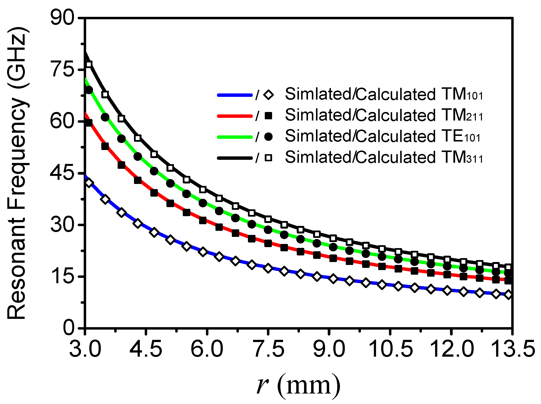
As illustrated in Figure 1, the antenna under study is based on an air-filled metallized spherical cavity with thickness of twall and radius of r, which is fed by a standard WR-90 waveguide segment with a length and height of LF and h, respectively, through a rectangular feeding window with LW × WF. Two groups of slots are symmetrically cut on the metallized cavity shell, which are named Group A and B. In Group A, there are seven slots, which are all symmetrical and parallel with the XOY-plane. The dimensions of slots in Group A are determined by width SA and angle αA, and the spacing between adjacent slots is WA. In Group B, there are two pairs of three slots, which are parallel with the XOZ-plane and symmetrical to the XOY-plane. The length and width of slots in Group B are LB and SB, respectively, and the spacing between adjacent slots is WB.

2.1. Resonant Modes

As mentioned in [21], multiple resonant modes exist in an air-filled metallized spherical cavity without any slots, and the frequencies of TM and TE modes can be determined as follows:
f TMnmp = ω TMnmp 2 π = y np 2 π r μ ε ,
f TEnmp = ω TEnmp 2 π = x np 2 π r μ ε ,
where r presents the radius of the air-filled metallized spherical cavity, ωTMnmp and ωTEnmp are the corresponding nature angular frequencies, μ and ε present the permeability and permittivity of the dielectric in the cavity, and xnp and ynp are the roots of the eigenvalue equations, i.e., Jn′(x) = 0, and Jn′(y) = 0.
Obviously, the resonant frequencies of TM and TE modes are not affected by the thickness of the metallized spherical cavity. Therefore, the thickness of twall can be preset to 2.0 mm for balancing sufficient mechanical strength and fabrication costs in this design. Considering that the function of the standard 90-WR waveguide segment is to connect the proposed antenna with measuring equipment, its corresponding dimensions also can be predetermined and summarized as h = 5.0 mm, LF = 22.86 mm, and WF = 10.16 mm.
For the modes of TM101, TM211, TE101, and TM311, in an air-filled metallized spherical cavity, their corresponding values can be calculated and expressed as 2.774, 3.870, 4.493, and 4.973, respectively. Thus, the resonant frequencies of the four aforementioned modes in free space can be simplified as follows:
f TM 101 = 1.3093 × 10 11 / r ,
f TM 211 = 1.8456 × 10 11 / r ,
f TE 101 = 2.1438 × 10 11 / r ,
f TM 311 = 2.3725 × 10 11 / r ,
where the unit of f is Hz while that of r is mm. Figure 2 plots the calculated and EM-simulated frequencies of TM101, TM211, TE101, and TM311 under different values of r, showing good agreement. In this design, the radius r is 12.5 mm, and the corresponding frequencies of these four resonant modes are 10.48, 14.76, 17.15, and 18.98 GHz, respectively.

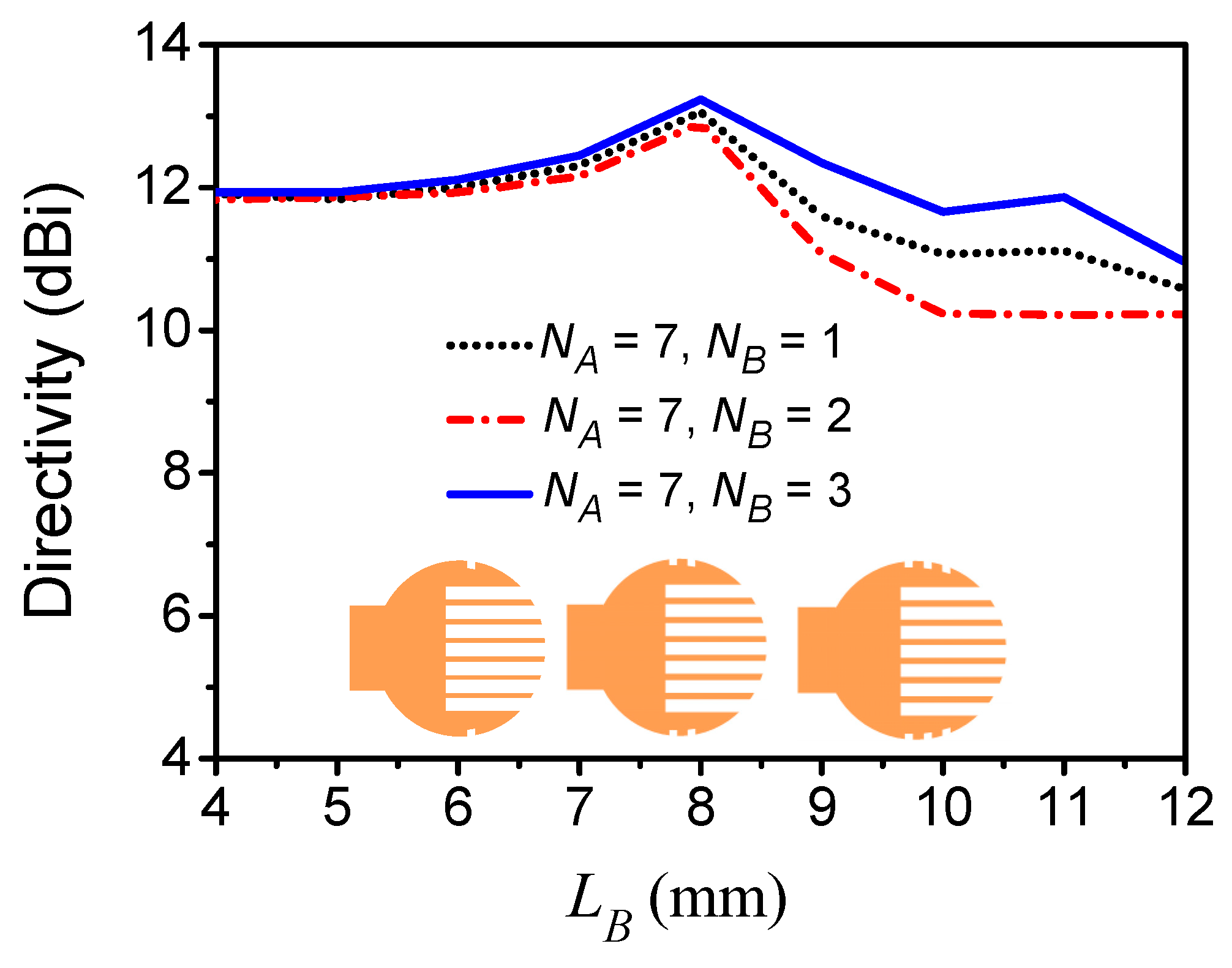
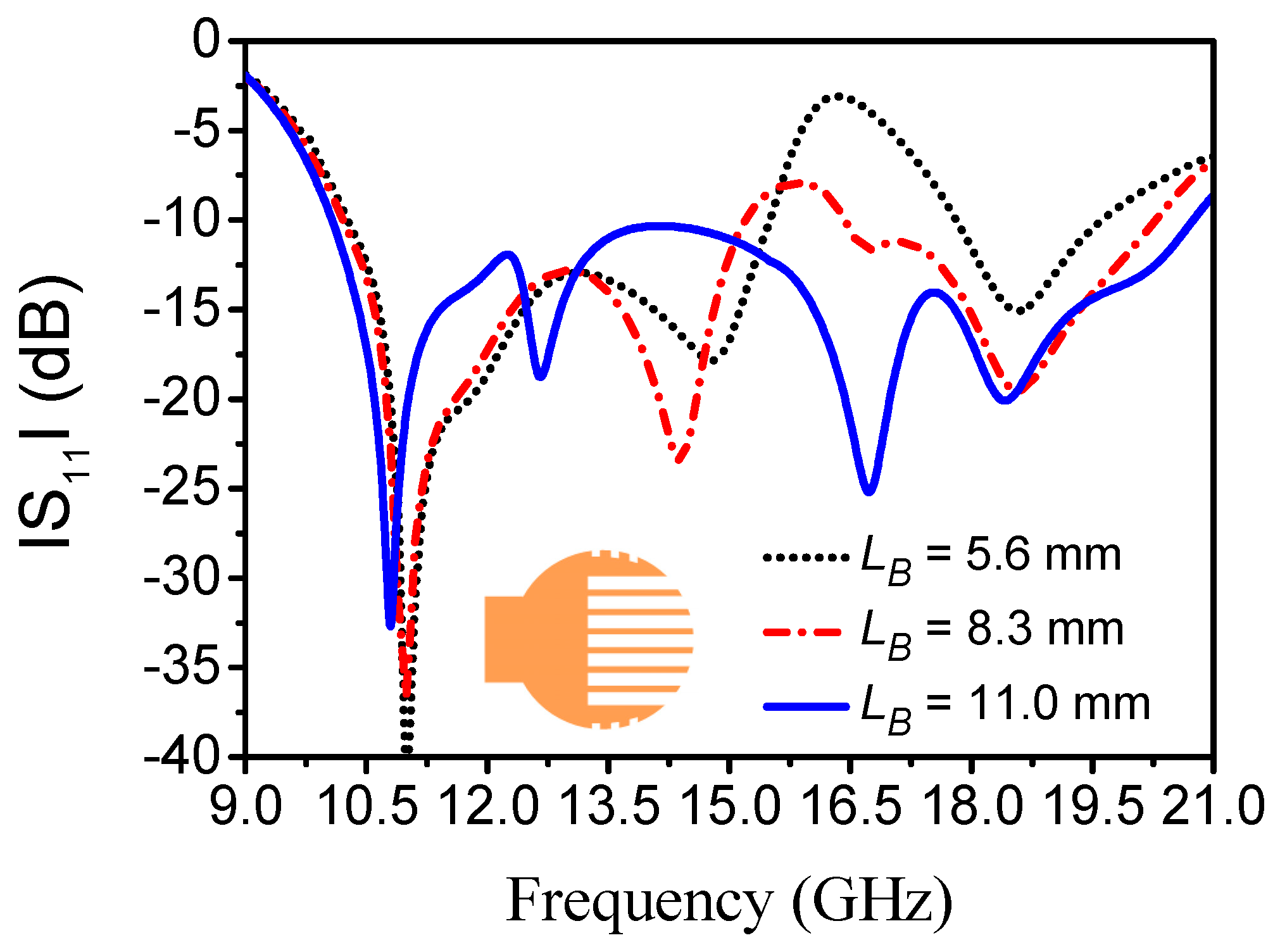
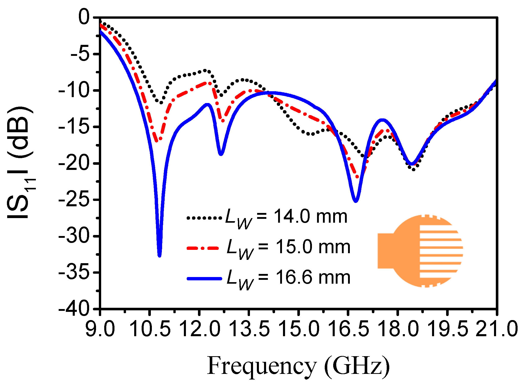
2.2. Design Principle of Wideband SWA

No energy can be radiated from an air-filled metallized cavity. To realize low cross-polarization and large radiation efficiency, slots, which are perpendicular to the surface current distributions of the metallized spherical cavity, should be symmetrically cut on the shell [22]. Thus, the first thing is to determine the surface current distributions of the metallized spherical cavity under the resonant modes of TM101, TM211, TE101, and TM311. As shown in Figure 3, the surface current directions of these four modes under study are perpendicular to the XOY-plane in blue dashed area while parallel to the YOZ-plane. Moreover, the surface current distribution of TE101 and TM311 modes also has a large current density in the red dashed area. Hence, the slots should be cut in these areas.
At first, slots are symmetrically cut in the blue dashed area, which are named Group A and parallel to the XOY-plane. In this case, a wideband SWA with dual resonances can be achieved. Its corresponding performances are simultaneously determined by the slot number of NA and dimensions of WA, SA, and αA. As WA and SA have relatively smaller effects on SWA performance, whose main function is to ensure the sufficient mechanical strength, they can be assumed as 1.0 and 2.0 mm, respectively, to simplify the design procedure. Then, the relationships among the antenna directivity, slot number of NA, and slot angle of αA can be studied, as shown in Figure 4. Apparently, the directivity becomes larger with the increase in NA. As αA increases, the directivity becomes larger at first and then remains almost unaltered, before finally becoming smaller. Thus, the slot number NA should be chosen as 7, while the slot angle should be around 190° for ensuring the maximum realized gain and radiation efficiency.
After determining WA, SA, and αA, the impedance matching of SWA near the two lower radiation modes of TM101 and TM211 is largely affected by the slot number NA, as shown in Figure 5. As the slot number NA increases, the impedance matching near the radiation modes of TM101 and TM211 improve, and these two radiation modes are merged with each other when NA = 7, resulting in a wideband SWA with two resonances.
From Figure 5, it is apparent that the antenna bandwidth can be further widened if the matching near 16.5 GHz is improved. Hence, other slots named Group B are then introduced in the red area exhibiting a large current density. Similar to the slots in Group A, the width and spacing of slots in Group B can also be assumed as 1.0 and 1.2 mm to simplify the design procedure. In addition, the relationships among the antenna directivity, slot number of NB, and slot length of LB are illustrated in Figure 6. With the increase in NB, the antenna directivity becomes larger. As LB increases, the antenna directivity becomes larger at first, before decreasing. Hence, the slot number NB should be 3 for ensuring the maximum directivity and radiation efficiency.
Under the condition of NB = 3, the matching near the upper two radiation modes of TE101 and TM311 are mainly determined by the slot length of LB, as illustrated in Figure 7. It is apparent that the impedance matching near these two radiation modes improves with the increase in LB, while that near the lower two modes of TM101 and TM211 is not deteriorated. Furthermore, these four modes are merged with each other when LB = 11.0 mm, resulting in a wideband SWA with four resonances.
In addition to the above parameters, the impedance matching is also significantly affected by the feeding window length of LW, as shown in Figure 8. It is apparent that the impedance matching near the two lower radiation modes is sensitive to LW, which has little effect on the matching near the two upper radiation modes. In this design, the length of feeding window LW is better chosen as 16.6 mm.
On the basis of the above discussion and analysis, a waveguide-fed SWA can be designed, whose simulated frequency responses of refection coefficient are shown in Figure 8 by the blue line. It is clearly observed that four radiation modes can be obtained in the proposed SWA. This indicates that four radiation modes in a single radiator can be successfully excited in a wide operation band.

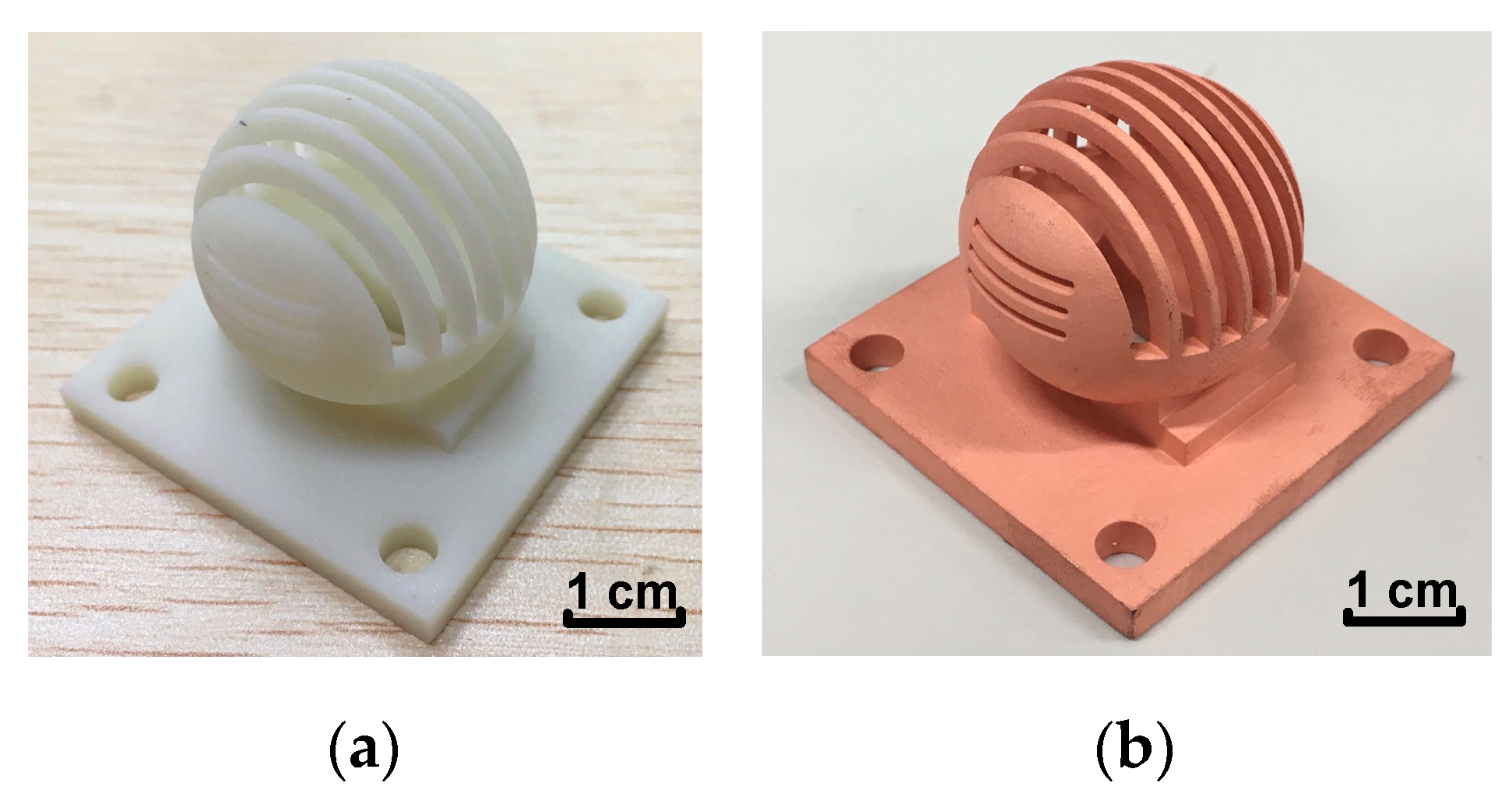
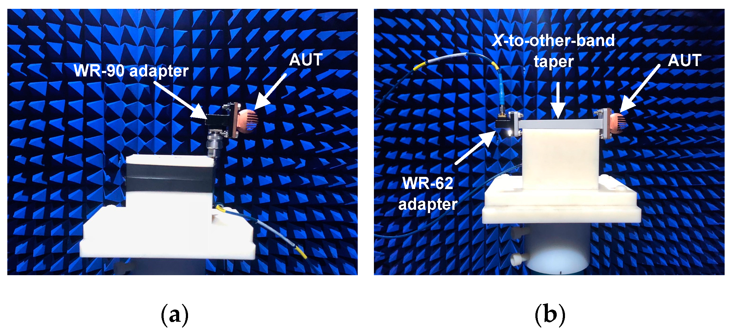
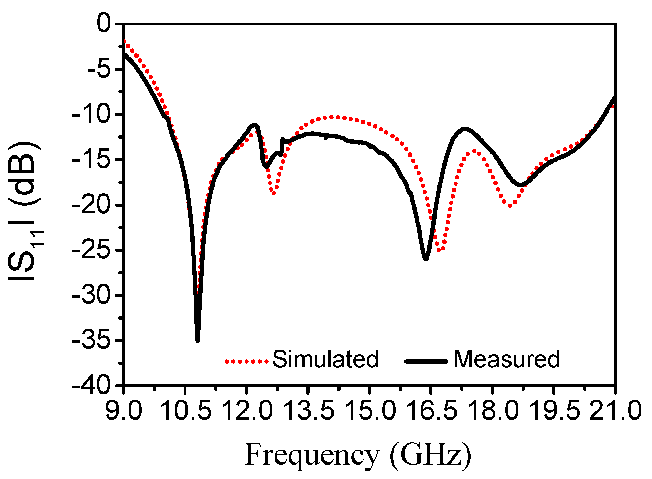
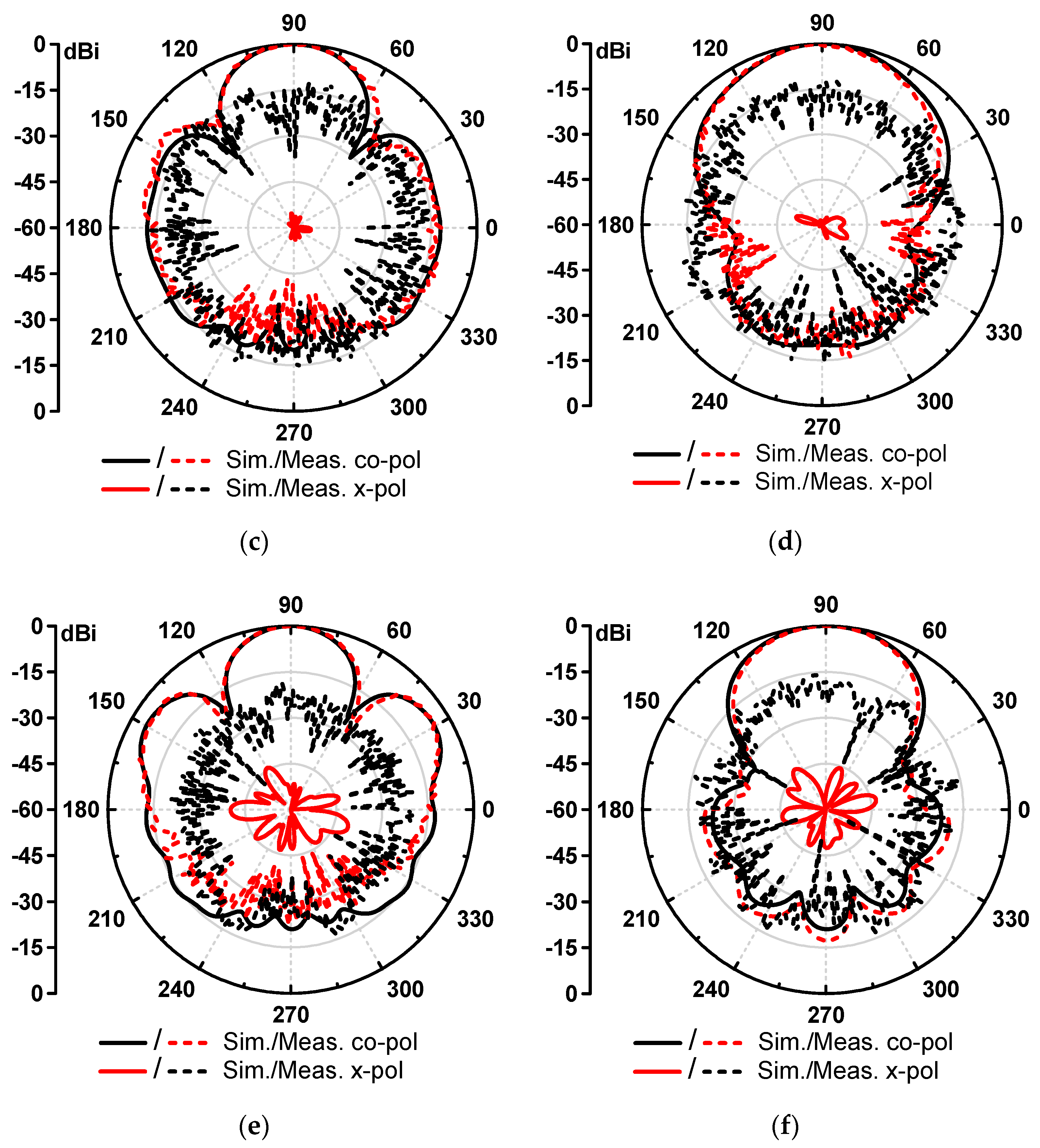
3. Fabrication and Results

For verification, a wideband SWA was designed and measured. The proposed SWA was fabricated using SLA and electroless copper technologies, whose advantages and fabrication processes were exhaustively explained in [19]. In order to minimize the SWA weight, a low-density ceramic-filled photosensitive resin was used as the printing material. After printing the resin structure, the surface metallization was performed with the help of a 10 μm thick conductive layer of copper. Figure 9 shows the photographs of the proposed antenna before and after metallization, which was fed by a WR-90 waveguide. The final dimensions of the proposed antenna were concluded as folows: r = 12.5 mm, LF = 22.86 mm, LW = 16.6 mm, WF = 10.16 mm, h = 5.0 mm, twall = 2.0 mm, WA = 2.0 mm, SA = 1.0 mm, αA = 190°, NA = 7, WB = 1.0 mm, SB = 1.2 mm, LB = 11.0 mm, and NB = 3. The overall size was 42.0 × 42.0 × 33.0 mm3, while the weight was only 13.0 g.
The reflection coefficient and radiation patterns were measured using a Keysight N5224A vector network analyzer and anechoic chamber, respectively. When measured at the X band, the antenna was connected with a WR-90 adaptor. When measured at other bands, the antenna was mated to a WR-62 waveguide-to-coax adapter through an X-to-other-band waveguide taper. In Figure 10, the measured set-ups in the anechoic chamber are illustrated.
In Figure 11, the measured and simulated reflection coefficients are compared with each other. Obviously, they are in good agreement with each other, and four measured radiation modes can be clearly observed at 10.81, 12.48, 16.37, and 18.69 GHz, respectively. Moreover, the impedance matching is better than −10.0 dB over a wide frequency range from 9.97 to 20.74 GHz. Hence, the FBW of the proposed SWA is 70.1%, while the center frequency (CF) is 15.36 GHz.
In Figure 12, the normalized radiation patterns of the proposed antenna at 11.0, 16.15, and 20.0 GHz are illustrated. It is apparent that the measured and simulated results agree well with each other. Within the impedance bandwidth, the sidelobes at the H plane were effectively suppressed, and the stable directional radiation patterns were maintained, while peak gain was absolutely located in the direction of θ = 90° and φ = 90°. Additionally, two sidelobes were found at the E plane, which became larger with the increase in operation frequency. This is because, with the increase in operation frequency, the surface currents in the red areas become larger, as shown in Figure 2. Hence, there will be energy radiated from these areas when the currents are disturbed by slots in Group B, and more energy will be radiated as the operation frequency increases. In Figure 13, the simulated and measured peak gains are presented with the radiation efficiency. Apparently, the measured peak gain is varied from 9.32 to 13.89 dBi within the operation bandwidth, while the average peak gain is 11.38 dBi. Furthermore, the radiation efficiency is above 91%.

4. Discussion

In general, the proposed method is more attractive in the design of high-gain and wideband SWAs. As the frequencies of multiple modes are only controlled by the inner radius of the spherical cavity, and the radiation modes can be merged with each other by suitably cutting some slots on the shell, some parameters, including the thickness of spherical cavity, spacing between adjacent slots, slot width, and dimensions of standard WR-90 waveguide segment, have relatively smaller effects on the antenna responses. To reduce the design complicity, these parameters can be preset by balancing sufficient mechanical strength and fabrication costs. Moreover, after knowing SWA center frequency and bandwidth, the inner radius and employed radiation modes can be decided. By investigating the surface current density under the employed radiation modes, the slot locations can be ascertained, and the slot number and length can be initially determined. For obtaining the best performance, the relationships among SWA responses, slot number, and length are studied. Of course, the feeding window affects the match near the two lower radiation modes, which also need to be investigated. After finishing the above steps, the final parameters of SWA with desired center frequency and bandwidth can be determined. Thus, this antenna is designed using an engineering design process, not a cut-and-try method.
On the other hand, there were some discrepancies among the simulated and measured results. These may have been caused by the fabrication precision, discontinuity effects, and so on. To highlight the merits of the proposed SWA, comparisons between this work and other high-power designs are listed in Table 1. Apparently, as the proposed SWA is a unit antenna fabricated by three-dimensional (3D) printing technology, it is light weight with a simple design process. Furthermore, the proposed SWA owns the widest operation bandwidth compared with other high-power antennas.

5. Conclusions

In this paper, a novel wideband waveguide-fed SWA with excellent radiation characteristics was presented. The proposed design was based on 3D printing and multi-mode technologies. By suitably introducing some symmetrical slots on the shell of a metallized spherical cavity, four radiation modes could be excited and merged with each other, resulting in a wide radiation characteristic. The measured results showed that the proposed antenna had the widest operation bandwidth and excellent radiation patterns. It can be anticipated that the proposed SWA will be extensively used in modern high-data-rate telecommunication systems.

Author Contributions

Conceptualization, X.B.; data curation, S.G.; formal analysis, X.B. and Y.Z.; funding acquisition, T.Y.; investigation, S.G. and Y.Z.; methodology, Y.Z. and T.Y.; resources, Y.Z.; software, T.Y.; supervision, T.Y.; validation, S.G.; writing—original draft, X.B.; writing—review and editing, X.B. All authors have read and agreed to the published version of the manuscript.

Funding

This work is supported in part by the Natural Science Foundation of China under Grant 61801298, the Foundation of Shenzhen under Grants JCYJ20170302142545828 and JCYJ20 180305124721920 and No.KQTD20180412181337494, and in part by the National Key Research and Development Program, China, under Subject No.2019YFF0216602, and the Foundation of Shenzhen University under Grants 2016057, 2019119, and 2019120.

Conflicts of Interest

The authors declare no conflict of interest.

References

  1. Wang, W.; Zhong, S.S.; Zhang, Y.M.; Liang, X.L. A broadband slotted ridge waveguide antenna array. IEEE Trans. Antennas Propag. 2006, 54, 2416–2420. [Google Scholar] [CrossRef]
  2. Kim, D.; Zhang, M.; Hirokawa, J.; Ando, M. Design and fabrication of a dual-polarization waveguide slot array antenna with high isolation and high antenna efficiency for the 60 GHz band. IEEE Trans. Antennas Propag. 2014, 62, 3019–3027. [Google Scholar] [CrossRef]
  3. Leung, K.W.; Chan, L.Y. The probe-fed zonal slot antenna cut onto a cylindrical conducting cavity. IEEE Trans. Antennas Propag. 2005, 53, 3949–3952. [Google Scholar] [CrossRef]
  4. Atamanesh, M.; Zahedi, A.; Abbasi-Arand, B. Design, simulation, and fabrication of a high-gain low-sidelobe-level waveguide slot array antenna at X-band with zero beam tilts in both azimuth and elevation directions. IEEE Antennas Wirel. Propag. Lett. 2020, 19, 811–815. [Google Scholar] [CrossRef]
  5. Ebadi, S.; Forooraghi, K. An annular waveguide slot antenna. IEEE Antennas Wirel. Propag. Lett. 2007, 6, 525–528. [Google Scholar] [CrossRef]
  6. Moradian, M.; Tayarani, M.; Khalaj-Amirhosseini, M. Planar Slotted Array Antenna Fed by Single Wiggly- Ridge Waveguide. IEEE Antennas Wirel. Propag. Lett. 2011, 10, 764–767. [Google Scholar] [CrossRef]
  7. Mallahzadeh, A.R.; Amini, M.A. Design of a leaky-wave long slot antenna using ridge waveguide. IEEE Antennas Wirel. Propag. Lett. 2014, 8, 714–718. [Google Scholar] [CrossRef]
  8. Lu, X.-L.; Gu, S.-M.; Wang, X.-C.; Liu, H.; Lu, W.-Z. Beam-scanning continuous transverse stub antenna fed by a ridged waveguide slot array. IEEE Antennas Wirel. Propag. Lett. 2017, 16, 1675–1678. [Google Scholar] [CrossRef]
  9. Farahbakhsh, A.; Zarifi, D.; Zaman, A.U. A mmwave wideband slot array antenna based on ridge gap waveguide with 30% bandwidth. IEEE Trans. Antennas Propag. 2018, 66, 1008–1013. [Google Scholar] [CrossRef]
  10. Zaman, A.U.; Kildal, P. Wide-band slot antenna arrays with single- layer corporate-feed network in ridge gap waveguide technology. IEEE Trans. Antennas Propag. 2014, 62, 2992–3001. [Google Scholar] [CrossRef] [Green Version]
  11. Huang, G.L.; Zhou, S.G.; Chio, T.H.; Hui, H.T.; Yeo, T.S. A low profile and low sidelobe wideband slot antenna array feb by an amplitude-tapering waveguide feed-network. IEEE Trans. Antennas Propag. 2015, 63, 419–423. [Google Scholar] [CrossRef]
  12. Zhou, S.-G.; Huang, G.-L.; Peng, Z.-H.; Ying, L.-J. A wideband full-corporate-feed waveguide slot planar array. IEEE Trans. Antennas Propag. 2016, 64, 1974–1978. [Google Scholar]
  13. Zhou, S.-G.; Dong, P.; Huang, G.-L.; Sim, C.-Y.-D.; Li, J.-Y. Wideband antenna array with full metal structure and air-filled microstrip feeding network. IEEE Trans. Antennas Propag. 2017, 65, 3041–3048. [Google Scholar] [CrossRef]
  14. Bi, X.-K.; Cheng, T.; Cheong, P.; Ho, S.-K.; Tam, K.-W. Design of dual-band bandpass filter with fixed and reconfigurable bandwidths based on terminated cross-shaped resonator. IEEE Trans. Circuits Syst. II Exp. Briefs 2019, 66, 317–321. [Google Scholar] [CrossRef]
  15. Bi, X.-K.; Zhang, X.; Wang, S.-W.; Yuan, T.; Guo, S.-H. Design of equal-ripple dual-wideband bandpass filter with minimum design parameters based on cross-shaped resonator. IEEE Trans. Circuits Syst. II Exp. Briefs 2020, 67, 1780–1784. [Google Scholar] [CrossRef]
  16. Zhu, Y.-J.; Li, J.; Zhang, X.; Yuan, T.; Zhong, Z.-P.; Tan, T.-Y.; Bi, X.-K. A 3-D printed spherical antenna with bandwidth enhancement under operation of dual resonance. IEEE Access 2020, 8, 19345–19352. [Google Scholar] [CrossRef]
  17. Le Sage, G.P. 3D printed waveguide slot array antennas. IEEE Access 2016, 4, 1258–1265. [Google Scholar] [CrossRef]
  18. Huang, G.-L.; Zhou, S.-G.; Chio, T.-H. Highly-efficient self-compact monopulse antenna system with integrated comparator network for RF industrial applications. IEEE Trans. Antennas Propag. 2017, 64, 678–681. [Google Scholar] [CrossRef]
  19. Somos. Stereolithography Materials. Available online: https://www.dsm.com (accessed on 8 October 2020).
  20. Zhu, Y.-J.; Li, J.; Huang, G.-L. A lightweight 3-D printed dual-band high gain slotted spherical antenna. IEEE Antennas Wirel. Propag. Lett. 2020, 19, 552–556. [Google Scholar] [CrossRef]
  21. Zhang, K.; Li, D. Electromagnetic Theory for Microwaves and Optoelectronics; Springer: Berlin, Germany, 2008; pp. 235–314. [Google Scholar]
  22. Silver, S. (Ed.) Theory of Slot Radiators. In Microwave Antenna Theory and Design; Peregrinus: Stevenage, UK, 1984. [Google Scholar]
Figure 1. Geometrical illustrations of the proposed slotted spherical waveguide antenna without a WR-90 waveguide flange: (a) YOZ-plane view; (b) XOY-plane view; (c) XOZ-plane view.
Electronics 09 01656 g001
Figure 2. Geometrical and EM-simulated eigenmode resonant frequencies of TM101, TM211, TE101, and TM311 modes versus the inner radius of the spherical cavity resonator.
Electronics 09 01656 g002
Figure 3. Simulation surface current distribution in a waveguide-fed metallic spherical cavity resonator: (a) TM101 mode; (b) TM211 mode; (c) TE101 mode; (d) TM311 mode. Left: YOZ-plane; right: XOY-plane.
Electronics 09 01656 g003
Figure 4. Simulated directivity of the waveguide-fed slotted waveguide antenna (SWA) at 10.8 GHz versus angle αA as a function of different NA.
Electronics 09 01656 g004
Figure 5. Simulated reflection coefficient of the waveguide-fed SWA as a function of different NA.
Electronics 09 01656 g005
Figure 6. Simulated directivity of the waveguide-fed SWA at 17.5 GHz versus length LB as a function of different NB.
Electronics 09 01656 g006
Figure 7. Simulated reflection coefficient of the waveguide-fed SWA respect to different LB.
Electronics 09 01656 g007
Figure 8. Simulated reflection coefficient of the waveguide-fed SWA as a function of different LW.
Electronics 09 01656 g008
Figure 9. Photographs of the fabricated SWA: (a) the three-dimensional (3D) printed prototype before surface metallization; (b) the copper-plated antenna.
Electronics 09 01656 g009
Figure 10. Photographs of the measured set-ups in the anechoic chamber: (a) in the measurement at the X band; (b) in the measurement at other bands.
Electronics 09 01656 g010
Figure 11. Simulated and measured reflection coefficients of SWA.
Electronics 09 01656 g011
Figure 12. Simulated and measured radiation patterns of the proposed SWA: (a) E-plane at 11.0 GHz; (b) H-plane at 11.0 GHz; (c) E-plane at 16.15 GHz; (d) H-plane at 16.15 GHz; (e) E-plane at 20.0 GHz; (f) H-plane at 20.0 GHz.
Electronics 09 01656 g012aElectronics 09 01656 g012b
Figure 13. Gains and radiation efficiency for the proposed SWA.
Electronics 09 01656 g013
Table 1. Comparison with previous SWAs. CF, center frequency; FBW, fractional bandwidth.
-TypesCF (GHz)FBWs (%)Reflection Coefficient EfficiencyFabrication Process
[10]Array13.520<−10>75%CNC
[11]Array15.213.8<−10>70%CNC
[12]Array12.5436.9<−10>60%CNC
[13]Array12.636.5<−10>70%CNC
[16]Unit12.340.9<−10>90%3D printing
[18]Array15.112.9<−14>90%3D printing
[20]Unit10.2/14.37.8/14<−10>90%3D printing
This workUnit15.3670.1<−10>91%3D printing

