Article

DoubleDeck: Decoupling Complex Control Logic of Network Protocols to Facilitate Efficient Hardware Implementation

1
Computer College, National University of Defense Technology, Changsha 410073, China
2
HuNan Hua Xin Tong Networks, Changsha 410073, China
*
Authors to whom correspondence should be addressed.
Electronics 2020, 9(10), 1647; https://doi.org/10.3390/electronics9101647
Submission received: 28 August 2020 / Revised: 5 October 2020 / Accepted: 7 October 2020 / Published: 10 October 2020
(This article belongs to the Section Computer Science & Engineering)

Abstract

:
A hierarchical method is often used to simplify the design of complex logic. However, when the hierarchical method is used to implement protocol control, there is no suitable decoupling method to divide the sophisticated protocol control into a series of small control logics. For this reason, this paper designs and implements the DoubleDeck model composed of a top state machine and a set of bottom state machines. The model divides the protocol control logic into protocol state conversion logic and processing logic based on hierarchical idea. Simultaneously, DoubleDeck also provides a bottom deck mapping mechanism (BDM) for all protocol control processing logic. Based on the BDM mechanism, developers can quickly implement the bottom state machine array. Next, we present the hardware design of DoubleDeck and prototype the time synchronization protocol on an FPGA array. The results show that DoubleDeck can be used as a design model to guide the implementation of complex protocol control logic. Compared with the finite state machine (FSM), DoubleDeck uses the BDM mechanism to implement three protocols can reduce the amount of code for developers by 30%.

1. Introduction

Networks and distributed systems need protocols to control the orderly data interaction between nodes [1]. The third-layer or higher protocols in the network are mostly implemented by software [2,3,4], which has high flexibility [5] and facilitates the rapid deployment of protocols by developers. However, with the emergence and development of 5th-Generation [6], Time-Sensitive Network (TSN) [7], and other communication technologies, the demand for data processing performance of networks and distributed systems continues to increase [8]. Traditional software-based protocols have difficulties meeting high-performance processing requirements due to problems such as poor processing performance and high processing latency [9,10]. For this reason, some recent studies [11,12,13,14] were proposed to improve the processing performance of the protocol by using hardware implementation protocols (i.e., FPGA, NP, and GPU).
In recent years, communication technology has made considerable development and progress, which has led to a continuous increase in the complexity of the protocol. Simultaneously, how to implement complex protocol control has become the main problem faced by hardware implementation protocols [15]. The complexity of protocol control is mainly reflected in two aspects. On one hand, while the protocol entity exchanges constantly changing status information with peers through data packets, it also needs to set up various timers to infer network status and the behavior of peer nodes. On the other hand, the protocol entity not only needs to monitor trigger events that occur asynchronously, but also needs to perform various synchronous and asynchronous processing operations. In the face of complex protocol control, the finite state machine model used in traditional hardware design not only has poor readability, but it is also difficult to describe and manage complex control behaviors with [16,17,18].
In order to simplify the design and implementation of complex control logic, some recent studies have proposed an implementation method based on a hierarchical state machine [19,20]. The hierarchical state machine provides a top-down description of complex control logic, which improves the readability of the model and simplifies the design of complex control logic. However, applying the hierarchical state machine to the design of complex protocol control logic faces two challenges: one is the lack of clear control logic division standards. The control logic of the protocol is a whole. How to set a common division standard for complex protocols to achieve effective control logic hierarchical division is still a problem that needs to be solved; the second challenge is the lack of efficient implementation methods of sub-state machine arrays. The original control state machine is divided into a series of sub-state machines that perform different functions. Designing and implementing all the sub-state machines separately increases the workload of developers to a certain extent. Existing research lacks efficient implementation methods of sub-state machine arrays.
In response, to address the above challenges, this paper proposes a DoubleDeck model that supports the hardware implementation of complex protocol control logic to simplify the complexity of protocol control logic design. The basic idea of DoubleDeck is to divide the states during protocol processing into global states and local states. The global states can be perceived by the protocol entity, while the local states are the opposite. Simultaneously, the global states and the corresponding transition logic constitute a top state machine to maintain the changes in the protocol processing stage. At the same time, the local states associated with the top states and the corresponding transition logic form a series of bottom state machines to control the detailed processing details of the processing stage.
Secondly, we proposed a bottom deck mapping (BDM) mechanism. Inspired by model-driven programming, the BDM mechanism shifts the development center of the bottom state machine from programming to programming abstraction. Considering the similarity of the bottom state machine processing logic, BDM abstracts a unified programming template for developers for all bottom state machines. Developers can easily use the programming template based on BDM to quickly implement the bottom state machine array.
In summary, our main contributions are as follows:
  • We have proposed DoubleDeck, a two-layer control model that facilitates hardware implementation of the protocol. DoubleDeck simplifies the design and implementation of complex protocol control by decoupling protocol control into protocol state conversion logic and processing logic.
  • We designed the BDM mechanism, a bottom deck mapping mechanism. BDM provides a general solution to the mapping problem between the bottom state machine array and the hardware logic, which effectively reduces the workload of the staff to develop the bottom state machine array.
  • Based on the DoubleDeck model, we implemented the Intellectual Property (IP) core of AS6802 protocol on Arria10 (Aletra FPGA) and conducted corresponding performance and resource overhead tests. Then, through the implementation of AS6802, Transmission Control Protocol (TCP) and Precision Time Protocol (PTP) processing control logic to evaluate the BDM mechanism.
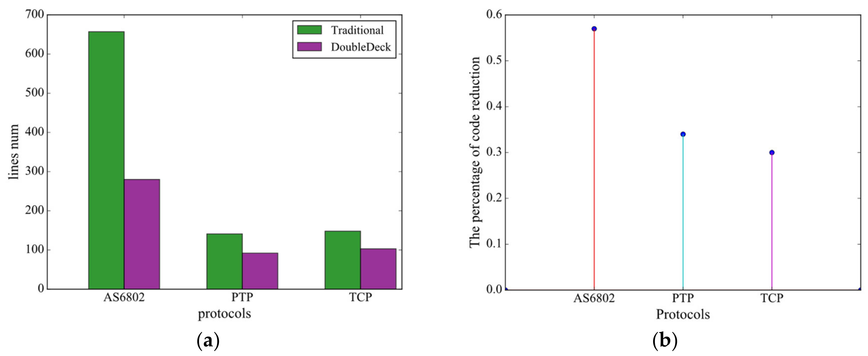
Experimental results show that the AS6802 IP core based on DoubleDeck has high performance. This shows that DoubleDeck can be used as a design model to guide the realization of complex protocol control logic. In addition, we implemented the control logic of AS6802, TCP and PTP by using the traditional the finite state machine (FSM) and DoubleDeck based on the BDM mechanism. This shows that DoubleDeck based on the BDM mechanism can reduce the amount of code development by 30% for developers.
The rest of this paper is organized as follows. Section 2 introduces the motivation of our work. Section 3 shows the overview of DoubleDeck and the BDM mechanism. The hardware design of DoubleDeck is proposed in Section 4. Section 5 presents the application and evaluation, followed by the related work and conclusions in Section 6 and Section 7.

2. Motivation

In this section, we describe the motivation of this work through early research and analysis of network protocols and their control logic.

2.1. Features of Network Protocols

The protocol agent of the same distributed network protocol is deployed on entities (hosts and other devices), and its control logic is responsible for controlling the orderly data interaction between entities, as shown in Figure 1. The control logic of the protocol agent consists of three parts: control state machine, timers and register sets. In addition, there are RX and TX modules in Figure 1, which are, respectively, responsible for message reception control and transmission control. Strictly speaking, the RX and TX modules belong to the processing logic of the protocol rather than the control logic. The control state machine is the most important part of the protocol control logic, which is used to control the jump of the protocol session state. As shown in Table 1, when the protocol agent is in a certain state, once the external input of the control state machine meets the conditions in the Guard (such as timeout, etc.), a corresponding command event (such as state transition, etc.) is generated.
Although the protocol agents of the same protocol are deployed on different hosts, the protocol agents may execute completely different control state machines (for example, the server side and the client side of the TCP protocol execute different state machines). The state transitions between the control state machines of the same protocol are interrelated. In the process of distributed network protocol processing, the protocol entity must obtain the network status and behavior of the opposite end to correctly complete the protocol-related processing. There are two main methods for the protocol entity to obtain the network information of the opposite end. First, in view of the characteristics of the packet type that can reflect the processing state of the protocol, the protocol entity exchanges state information with the peer through multiple protocol-related packets. For example, as shown in Table 1, when host2 in S1 (S11) receives Pa, host2 can infer that host1 is in Sa. Second, the protocol entity sets up a series of timers to infer the status information of the peer. For example, when host2 finds that the timer T1 has timed out, host2 can determine that host1 needs to complete the operation in the Sa state. At this time, host2 sends Px to notify host1 to perform operations such as state transitions.
Through the analysis of the protocol, we found that the protocol entity not only needs to monitor the packet type of the opposite end, but also monitor the change of the timer set by the protocol entity itself. In addition, while the protocol entities perform synchronous operations, they also perform asynchronous operations. For example, when host2 in Table 1 receives protocol-related messages (Pa and Pb) in the S1 state, the protocol entity does not consider the subsequent situation and directly executes the corresponding operation. At the same time, when host2 receives an irrelevant message, it performs a synchronization operation. Host2 waits until the value of T1 exceeds the threshold before sending the feedback result to host1.

2.2. Decoupling of Protocol Control Logic

The finite state machine model and its variants are effective means to describe the protocol logic [15]. It uses multiple variable values to describe the state to maintain protocol processing. During the execution of the protocol, the protocol entity showed a diversified state. Among them, part of the state is necessary information for the event processing or state transition of the peer end of the protocol, so the protocol peer needs to be aware of this kind of state; part of the state can be set to an externally invisible state because it involves event processing and state transition of the peer end of the protocol. In terms of whether the protocol state is externally perceptible, we divide the protocol state into a global state that can be perceived by the peer of the protocol and a local state that is not visible from the outside.
Global state. The definition of the global state is based on the processing stage of the protocol. The global state is the state that the peer of the protocol can perceive during the processing of the protocol and reflects the processing stage of the protocol agent. In addition to using packet interaction information and counter timing, the protocol agent senses the peer status. For example, in Figure 2a, there are two hosts interconnected by a network. The TCP protocol is deployed on the host and serves as a TCP client and a TCP server, respectively. When the server in the CLOSED state receives the SYN issued by the client, it can perceive the state of the client and perform the corresponding action. If the client does not receive the SYN and ACK of the server after a long period of time, it is perceived that the state of the server does not conform to that shown in Figure 2a.
Local state. The definition of local state is based on flow rules. The local state is the state that the outside world does not need to be aware of during the packet processing of the protocol and reflects the processing details of the protocol agent in a global state. The local state is closely related to the dynamic information generated by the protocol entity, such as the reception of new messages and the change of the counter value. Figure 2b shows the local state and action description of the server side in the CLOSED state, which expresses the details of the processing of the server side in the CLOSED state.
According to the features of the protocol, the protocol control decouples into the conversion logic and processing logic of the protocol state. Among them, the conversion logic maintains the transfer and actions of the global state of the protocol entity, as shown in Figure 2a, the Client switches from the CLOSED state to the SYN-SEND state; the processing logic manages the transfer and actions of the protocol entity in the local state. The table in Figure 2b describes all the local states and actions of the Server in the CLOSED state. The decoupling conversion logic and processing logic are relatively simple, which is convenient for design and testing.
According to previous research, we found that two types of states can be shown during the protocol processing. Therefore, we can decouple the protocol control logic into global state-related conversion logic and local state-related processing logic. In this article, we propose a two-layer state machine design model to simplify the design and implementation of complex protocol control logic by dividing complex protocol control logic into small conversion logic and processing logic.

3. DoubleDeck Design

In this section, we propose the DoubleDeck model, which abstracts the protocol control logic into the top state machine and the bottom state machine array. Then, we propose an efficient implementation mechanism of the bottom state machine—the bottom deck mapping mechanism (BDM), and introduce specific implementation in detail.

3.1. DoubleDeck Model

3.1.1. Design Ideas

Based on the hierarchical idea, DoubleDeck converts the complex flat finite state machine model into a two-layer finite state machine model to reduce the complexity of the protocol control logic implementation.
According to whether the state is externally visible, DoubleDeck divides the processing state of the protocol into the top state (i.e., global state) that is perceivable by the protocol peer and the bottom state (i.e., local state) that is not visible from the outside. The top state and its conversion logic constitute the top state machine, as the conversion logic that controls the global state conversion in the protocol control logic. At the same time, based on the correlation with the top state, the bottom state is further divided and clustered to form a series of bottom state machine arrays associated with the top state. The bottom state machine is responsible for implementing specific event processing in the global state, that is, processing logic. The top state machine controls state transitions, which intuitively reflects the current processing stage of the protocol. The bottom state machine array implements event processing according to the description of the conversion table, reflecting the details of protocol processing.
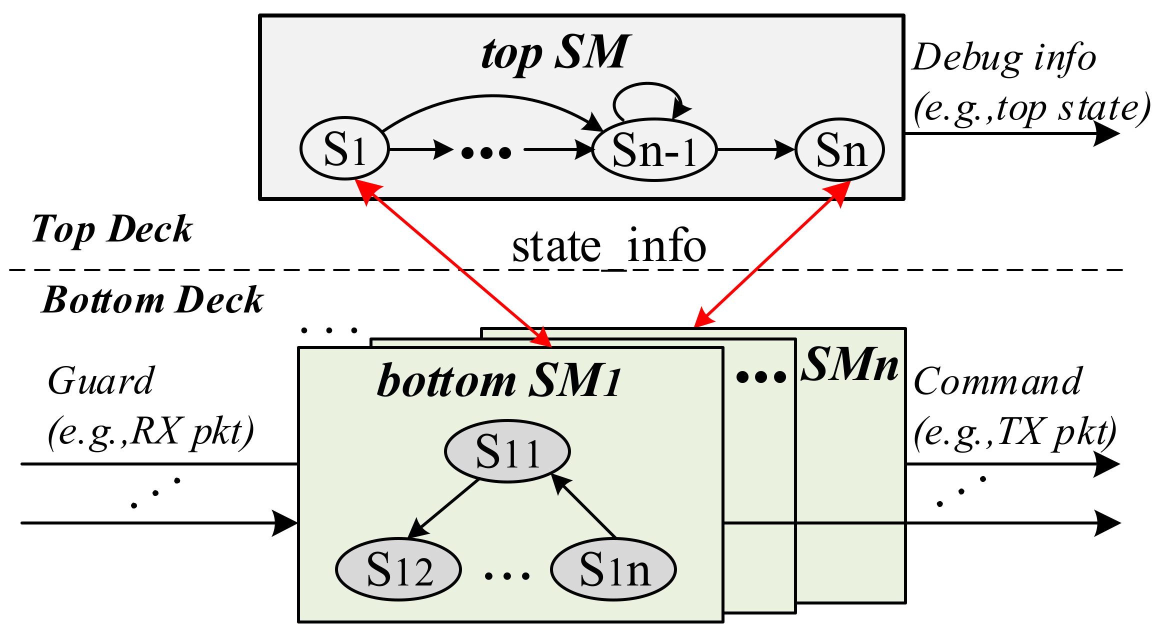
According to the previous description, DoubleDeck can decouple the control logic of the protocol into conversion logic and processing logic and map them to the top state machine and the bottom state machine array, respectively. As shown in Figure 3, the global state and its transition logic constitute the top state machine of DoubleDeck; the local state and its transition logic constitute the bottom state machine array of DoubleDeck. Indirect communication is used between the bottom state machines, that is, the bottom state machine that is completing event processing controls the other bottom state machines for event processing through the top state machine. This indirect communication method removes the coupling between the bottom state machines due to state jumps and splits the flat protocol control state machine.

3.1.2. DoubleDeck Model Overview

On the basis of giving design ideas, we now introduce the proposed DoubleDeck model. DoubleDeck consists of top deck and bottom deck, as shown in Figure 3. There is a top state machine on the Top deck, which is responsible for maintaining the global state of the protocol and its corresponding transition logic. The Bottom deck consists of a series of bottom state machines. The bottom state machine implements the processing logic in the global state and provides control information for the state transition of the global state.
The top state machine is responsible for maintaining the changes in the processing stage of the protocol entity. The top state machine is at the top of the control plane, which is convenient for reading global state information. It transmits status information to external devices such as CPU to complete debugging, maintenance and other tasks. In addition, the top state machine exchanges information with the bottom state machine corresponding to the current global state. It uses the state_info signal to control the bottom state machine to jump from the waiting state to the active state and wait for an external trigger event (i.e., DoubleDeck’s monitoring event) to be generated. At this point, the bottom state machine corresponding to the global state begins to process data. At the same time, the state transition of the top state depends on the control information of the bottom state machine. The bottom state machine that completes the processing task transfers the next stage of the protocol processing (i.e., the subsequent global state) to the top state machine through the state_info signal. The top state machine performs corresponding state transitions according to the signals of the bottom state machine and continues to exchange information with the bottom state machine array.
The bottom state machine array processes external trigger events based on flow rules. The bottom state machine has three states, which are waiting state, active state and end state. Among them, the active state has multiple processing states, that is, the partial state mentioned above. When the data plane receives protocol-related traffic, the external RX module extracts the information needed by DoubleDeck and sends the information to the bottom state machine array. The bottom state machine in the active state receives information. For the bottom state machine, this information is an external trigger event. Once the external event meets the monitoring conditions of the conversion table, the bottom state machine enters the appropriate local state and generates a command event according to the state table (see Table 1). When the command event contains global state jump information, the bottom state machine enters the end state and uses the state_info signal to notify the top state machine to perform state transitions. After the top state machine completes the state transition, it controls the bottom state machine corresponding to the global state to enter the active state. In addition, DoubleDeck sends command events to the processing logic of the protocol. The processing logic of the protocol constructs appropriate data packets according to the command events generated by the control logic of the protocol and executes the corresponding event processing.

3.2. The Bottom Deck Mapping Mechanism

The bottom deck mapping mechanism (BDM) proposed in this section aims to solve the problem of mapping between the processing logic of local state association and the bottom state machine array. The BDM mechanism uses formal means to define this mapping problem and provides an efficient implementation mechanism.

3.2.1. Problem Formalization

The mapping problem between protocol-controlled processing logic and the bottom state machine array is essentially the mapping problem from the abstract conversion table to a series of finite state machines. The entries of the conversion table are associated with the global state. All the entries associated with each global state represent the processing logic in that state, that is, these entries can be mapped to a finite state machine that is convenient for hardware implementation (we call it a sub-finite state machine).
To facilitate the formal description of the mapping problem, we have defined the graphs and tables involved in the problem. The guardianship events and command events for the protocol are composed of a limited number of basic events. We can define the guard events and command events in the conversion table in Figure 3 as compound variables (such as structures). Generally speaking, guardianship events include basic events such as the type of received message and timer timeout. Command events include the next basic events such as the processing status, the type of message sent, and the timer timeout. Of course, the characteristic protocol has specific basic events, such as whether the number of synchronization nodes in the time synchronization protocol exceeds the threshold and other protocol-specific events.
State transition table. We divide the transition table into a series of state transition tables associated with global states. Each state transition table corresponds to all processing rules in a global state. The state transition table is composed of three parts, including the line number, the guardianship event of the current state and the command event generated when the guardianship event occurs. Based on the above two formal definitions of compound variables, we abstract the state transition table into tuples B = (L, G, C), here:
  • L represents the number of rows, ie L ∈ {num}, where num ∈ [1, N], N represents the total number of rows;
  • G represents the set of triggering events, ie G ∈ {g}, where g ∈ g[N] is defined by the guardianship event;
  • C represents the set of operation sequences, ie C ∈ {c}, where c ∈ c[N] is defined by the command event.
Sub finite state machine. We use the bottom state machine array to abstract a common form of expression, the sub-finite state machine model (SFSM). Among them, the Px (P1, P2, …, Pn) state corresponds to the nth row entry in the state transition table and generates a corresponding guardianship event according to the processing rules. The idle, guard, and exit states are additional states added to achieve orderly transitions between processing states. We define SFSM as a quintuple (F, D, m, T, C), here:
  • F = (D, m, T, C), F is a graph.
  • D represents a set of states, that is, D ∈ {P1, P2, …, PN, idle, guard, exit}, where Si = Li (i ∈ [1, N]).
  • m represents the total number of states, m = N + 3.
  • T represents the set of transition conditions, that is, T ∈ {T1, T2, …, TN, start, end, finish}, where Ti = gi(i ∈ [1, N]), and g [N] is defined by the Guard structure.
  • C represents the set of action events corresponding to the state, that is, C ∈ {c1, c2, …, cN}, where c[N] is defined by the Command structure
After relevant research, we found that the mapping problem between the state transition table and the sub-state machine is to map table B into graph F. In the state transition table, there are N rows of entries. These table entries correspond to the N processing states Px (P1, P2, …, PN) of the graph F. In addition, there are three states (idle, wait, and exit) in F to achieve an orderly state transition between processing states.
The processing flow of SFSM is as follows. First, SFSM is in idle state, waiting for the start information of the top state machine (step one). Then, SFSM enters the guard state and waits for the monitoring event to occur. Once SFSM finds that a monitoring event occurs, SFSM enters the corresponding processing state Px (step two). SFSM generates specific command events in state Px and returns to the guard state after completion. When the command event generated by the state Px includes a state jump, the jump condition finish is satisfied (step three). Finally, when the jump condition finish is satisfied, SFSM enters the exit state. After waiting for a while, SFSM enters the idle state (step 4). Among them, step two and step three are a cyclic process.

3.2.2. Deck-Map Algorithm

Realizing the mapping between the state transition table and SFSM is the prerequisite for realizing the bottom state machine array. There is a mapping relationship between the state transition table of a single global state and the state in SFSM. Based on the formalization of the above problem, this paper designs an algorithm to map the state transition table to SFSM. The pseudo code is shown in Algorithm 1.
Algorithm 1 Deck-Map
Input: table Tabtransition
Output: SFSM Fcode
1: Fcode.state_num = len(Tabtransition.line) + len(initial_states)
2: for index = 0 to Fcode.state_num do F.D.append (idle)
3: if index >= len(Tabtransition.line) then  #general initial_states = [idle, guard, exit]
4:  Fcode.state.append(initial_states)   # initial_transition = [start,finish,end]
5:  Fcode. initial_states.transition[index] = initial_transition[index]
6: else # The following code maps the state of table and SFSM
7:  Fcode.state.append(process_states[index])
8:  Fcode.guard.transition[index] = Tabtransition.line[index].Guard
9: end if   # Control the transition from processing state to guard state and exit state
10: if next_state in Tabtransition.line[index].Command then
11:  Fcode. process_states[index].transition = finsih
12:  Fcode. process_states[index].next_state = exit
13: else
14:  Fcode. process_states[index].transition = end
15:  Fcode. process_states[index]. next_state = guard
16: end if
17: end for
In the Deck-Map algorithm, first determine the number of vertices in the graph Fcode (the first line of pseudocode). In lines three to five of the pseudo code, the graph Fcode sets the initial states (idle, wait, and end) as vertices, and sets the transition conditions between the initial states. The next three lines (line six to line eight of the pseudocode) map each line entry in the conversion table to Fcode as a processing state, and use the guard threshold of the conversion table entry as the conversion conditions from the guard state to the processing state. The 9th to 15th lines of the pseudo code determine that the processing state is switched to the exit state or the guard state through conditional judgment. The basis of the judgment is whether the command threshold of the conversion table entry includes global state switching. Moreover, this code adds the transition conditions from the processing state to the exit state and the guard state for Fcode.

3.2.3. Workflow of the Bottom Deck Mapping Mechanism

The BDM mechanism is based on a model-driven programming approach, shifting the focus of development from programming to high-level abstractions in pursuit of efficient implementation. It first decouples the conversion table abstracted from the protocol into a state conversion table array, then abstracts the general expression form of the state conversion table, and finally implements the bottom state machine array based on the Deck-Map algorithm. Next, we detail the implementation steps of the bottom state machine array, as shown in Figure 4.
Decoupling conversion table. We abstract the control logic of the protocol into a combination of conversion table and control state machine, as shown in Figure 4. To simplify the design, we map the conversion table to an array of DoubleDeck’s bottom state machines. Considering that each bottom state machine corresponds to a processing logic in a global state, that is, a collection of partial entries in the state table. Taking the global state as the decoupling standard, we decouple the conversion table into a series of state conversion table arrays under the global state.
Abstracting the general expression of state transition table. After decoupling the transition table into a state transition table array, we consider how to use model-driven programming to simplify the design and implementation of a large number of state transition tables. Combined with the previous research, we found that the state transition tables of the same protocol have similarities, and a formal expression method can be used to define a common expression form for the state transition tables. Then, we implement the mapping procedure based on the Deck-Map algorithm proposed above to map the general state transition table to the SFSM.
Programming implements the bottom state machine array. Finally, we implement SFSM based on hardware programming languages such as Verilog or Very High Speed Integrated Circuit Hardware Description Language (VHDL), and obtain a general programming template for the state transition table. In the specific implementation process of the bottom state machine array, we only need to instantiate the SFSM and modify the parameters of the programming template to obtain the code of the bottom state machine array.

4. DoubleDeck Hardware Design

In this section, we describe the hardware design of the DoubleDeck model (see Figure 5). DoubleDeck contains two Decks, Top Deck and Bottom Deck. Top Deck mainly realizes the jump of the conversation state and maintains the access and modification of global data. In addition, Top Deck provides Debug Application Programming Interface (API) that interact with the outside world, which lays the foundation for later code debugging and equipment maintenance. On Bottom Deck, the bottom state machine array is designed to complete the function of the state transition table.

4.1. Top Deck Design

In Top Deck, the core is the Top_SM module used to maintain the protocol processing state. Top state machine (SM) implements the control state machine of the protocol. Top SM receives the start signal from the outside and enters the initial state S1. The typical start signal is the reset signal. In other cases, Top SM needs to receive a feasible State Date Interface (SDI)_in if it wants to make a state transition. SDI_in will carry information about the next state of Top_SM. A Global variable Module (Global VM) is mainly used to maintain global information closely related to the protocol, including key parameters of the protocol and variables that multiple modules in Bottom Deck will access and update. The initial value of the global information can be conFigured by the external CPU, or the initial value can be set during encoding. In addition, Top Deck has designed a series of Debug APIs for external access. Through these APIs, we can grasp the stage in which the protocol is running and the value of global variables at that stage.

4.2. Bottom Deck Design

Bottom Deck is mainly composed of an array of bottom state machines. When the network data related to the protocol passes through the bottom data plane, the RX module sends the data message to the Bottom Deck. In order to reduce the use of hardware resources, the RX module extracts key information from the data stream and sends it to the Bottom Deck instead of all the data. DoubleDeck designed the demultiplexer (DMUX) module to select the active bottom state machine to process the data. The selection signal of DMUX comes from Top Deck’s Top SM module. At the same time, after receiving the data from the data plane, DMUX reads Variable Date Interface (VDI)_out of Global VM. VDI_out and key constitute the input of the bottom state machine, that is, the monitoring event of the bottom state machine for state transition and event processing. When the processing of the bottom state machine in the active state is completed, the result, that is, the command event is sent to the bottom processing module of the device. In addition, the bottom state machine will send state transition information (SDI_in) and global information (VDI_in) to Top SM and Global VM, respectively.
The bottom state machine array is the core of Bottom Deck. The design goal of each bottom state machine is to implement a state transition table for the global state. As shown in the block diagram on the right of Figure 5, we designed a state transition table module. It contains:
  • RX. RX mainly has the function of integrating data. For the data plane key and the information carried by VDI and SDI in Top Deck, the RX module encapsulates them into a pre-defined data format.
  • SFSM. SFSM contains multiple processing states. Each processing state corresponds to a row of entries in the state transition table of the global state. After DoubleDeck enters the initial state, SFSM will enter the wait state. When the guard meets the transition condition of a certain processing state, SFSM will enter the processing state and execute the corresponding command event.
  • Timer. In many protocols, the processing time of the state is limited and varies. Timer is a module for maintaining timeout events. Because each state has different time limits, we use timer as a submodule of the bottom state machine.
  • TX. For the processing results of the bottom state machine, the TX module sends these results to the data plane and Top Deck according to a pre-defined data structure without performing any additional operations.

4.3. Communication Mechanism

In this section, we will describe the communication mechanism designed in DoubleDeck. DoubleDeck is mainly used to describe the complex control logic of the protocol. The communication mechanism of DoubleDeck is divided into two aspects, including the internal communication mechanism between DoubleDeck internal Decks and the external communication mechanism between DoubleDeck and external processing modules.
Internal communication mechanism. In DoubleDeck, Top Deck needs to read data from Bottom Deck whether it is performing state jumps or updating global information. Bottom Deck not only requires Global VM to provide register information, but also Top SM control data guard to enter the active bottom state machine. The internal communication mechanism of DoubleDeck is mainly composed of State Date Interface (SDI) and Variable Date Interface (VDI). SDI adopts the “bitmap” method, that is, each bit corresponds to a bottom state machine. When Top SM detects that the bit position in SDI_in is “1”, the state jumps to the state corresponding to the bit. In Bottom Deck, DMUX receives SDI_out from Top SM, which works similarly to SDI_in. At the same time, VDI_in and VDI_out are used to realize the data exchange of global information between Decks. On the one hand, the bottom state machine array can read global information through VDI_out. On the other hand, Global VM can also update global information through VDI_in. Through VDI and SDI, DoubleDeck enables multiple bottom state modules to share global information, avoiding direct communication between bottom state machine modules. Using the indirect communication mechanism of the bottom state machine, we have reduced the degree of coupling between the array of bottom state machines, enhanced the independence of the bottom state machine, and facilitated later maintenance and the addition and deletion of the bottom state machine.
External communication mechanism. The external communication mechanism is responsible for data interaction between DoubleDeck and external modules. When protocol-related data packets pass through the bottom data plane, the data plane extracts key information to save resources. As shown in Figure 5, the RX module of the bottom data plane extracts the key information of the message and transmits the key information to DoubleDeck. The bottom state machine generates a command event after completing data processing, and sends the information required by the bottom data plane in the command event to the TX module of the bottom data plane. At the same time, considering whether it is early debugging or later maintenance, developers need to obtain internal global information. DoubleDeck sets up a Debug APIs module on Top Deck. Through this module, users can obtain a large amount of information for debugging and post-maintenance, such as the state of the protocol and the type of packets being processed by the protocol.

5. Application and Evaluation

In this section, we demonstrate and evaluate the application of the DoubleDeck model and BDM mechanism. First, we implemented the AS6802 IP core based on DoubleDeck and demonstrated the state transition of the AS6802 protocol. In addition, we tested the performance and resource overhead of the AS6802 IP core. Finally, in order to prove the feasibility of the BDM mechanism based on DoubleDeck, we compared the programming method based on the DoubleDeck model and the BDM mechanism with the traditional programming method based on FSM using three protocols as examples.

5.1. Application

Based on the DoubleDeck model, the AS6802 protocol prototype system is implemented on a network processing platform composed of four Arria10 FPGAs. The FPGA chip has 367,180 Slice Look-Up Tables (LUTs), 734,360 Slice registers, and 1431 M20K RAM tiles.
AS6802 protocol. The AS6802 protocol describes a fault-tolerant high-precision time synchronization algorithm [21], which is widely used in time-triggered networks (TTE). Synchronization master (SM) and compression master (CM) are two necessary roles of the AS6802 protocol. Through the periodic data exchange between SM and CM, TTE network realizes high-precision time synchronization.
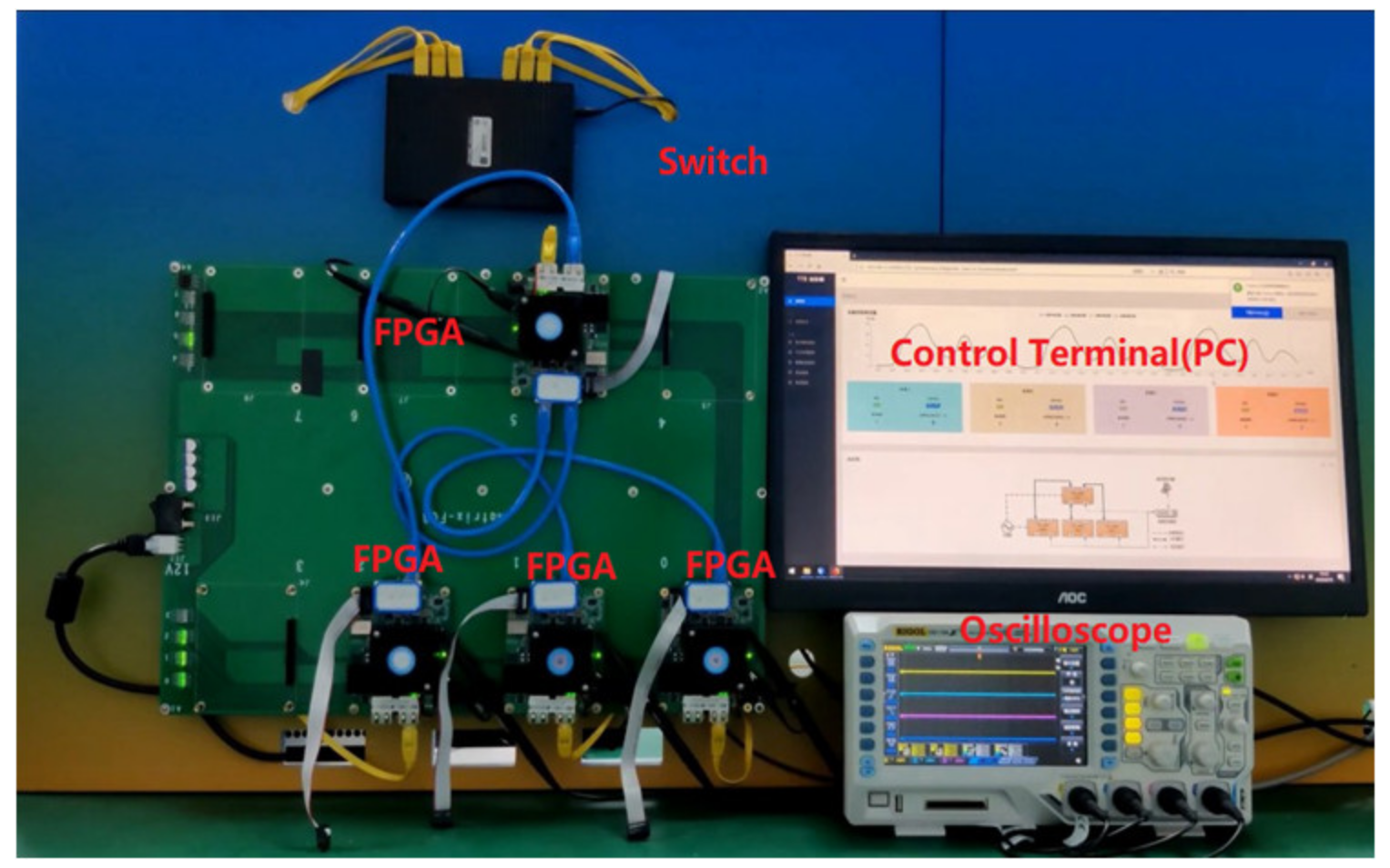
Experimental environment. The test platform contains four FPGAs, and a simple L2 switching function was implemented on each FPGA, as shown in Figure 6. In the experiment of the AS6802 protocol, the test network adopts star topology. In addition, there is an oscilloscope, a switch and a control terminal (PC) in the test environment. The oscilloscope is used to detect the synchronization pulse signal of each node and calculate the error between the synchronization pulses in real time. The controller forms an out-of-band configuration network with all nodes through switches to realize the configuration and status monitoring of each node.

5.1.1. Model Feasibility

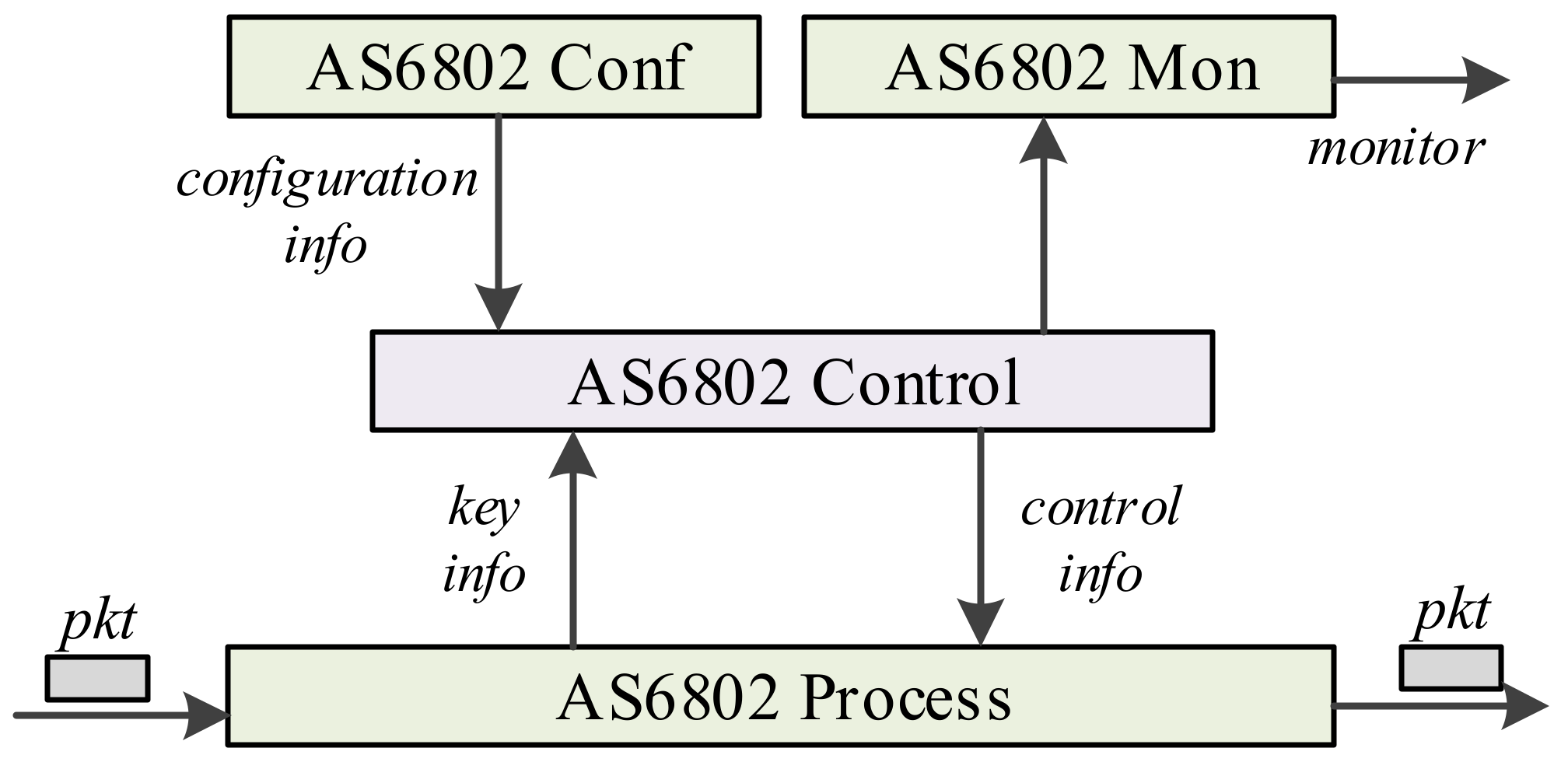
We implemented the IP core of the AS6802 protocol based on the DoubleDeck model, as shown in Figure 7. When the AS6802 IP core receives messages related to the protocol, it first enters the AS6802 Process. We complete the extraction of key information and the processing of command events on the AS6802 Process. AS6802 Control generates control information with corresponding command events based on the extracted key information. In addition, AS6802 conf is responsible for configuring key parameters in the AS680 protocol; AS6802 Mon is responsible for monitoring status information in AS6802 Control.
AS6802 Control is a key control component of the AS6802 IP core, which is based on the DoubleDeck model. The global state comes from the original control state machine of the protocol [21]. At the same time, we analyze the control logic of the protocol and abstract state transition tables which are similar to Table 1. A row of entries in the same global state is defined as a local state in the global state. In the design stage, we decouple the control logic of the AS6802 protocol according to ideas of DoubleDeck and divide the states in the protocol processing process into 13 global states and 61 local states. The number of local states corresponding to the global state is shown in Table 2. Then, we add the corresponding transition logic to map the global state and the local state to the Double Deck’s Top Deck and Bottom Deck, respectively. The protocol describes the global state and its transition in detail, which is convenient for us to give the design of top SM in Top Deck quickly. We can also design the state transition table of the AS6802 protocol (similar to Table 1) according to the data processing rules in each global state in the AS6802 protocol. Each row entry in the state transition table corresponds to a local state. Simultaneously, according to the associated global state, DoubleDeck further clusters the local states to form a series of local state machine arrays. Therefore, we can quickly realize the design of the Bottom SM array in the Bottom Deck. Through the above description, we found that by observing and analyzing the control logic of AS6802, we can quickly give the design scheme of AS6802 Control based on DoubleDeck. More detail and source codes are available at gitee [22].

5.1.2. Performance and Resource Utilization

In order to evaluate the performance of the DoubleDeck model, we used the AS6802 IP core to instantiate four nodes in the experimental environment in Figure 6. The AS6802 IP core can be instantiated as the SM module or CM module. In Figure 6, the upper FPGA deploys the SM module, and the lower three FPGAs deploy CM modules.
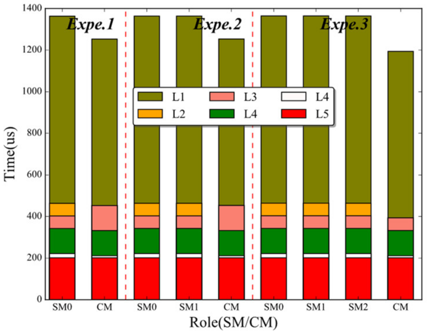
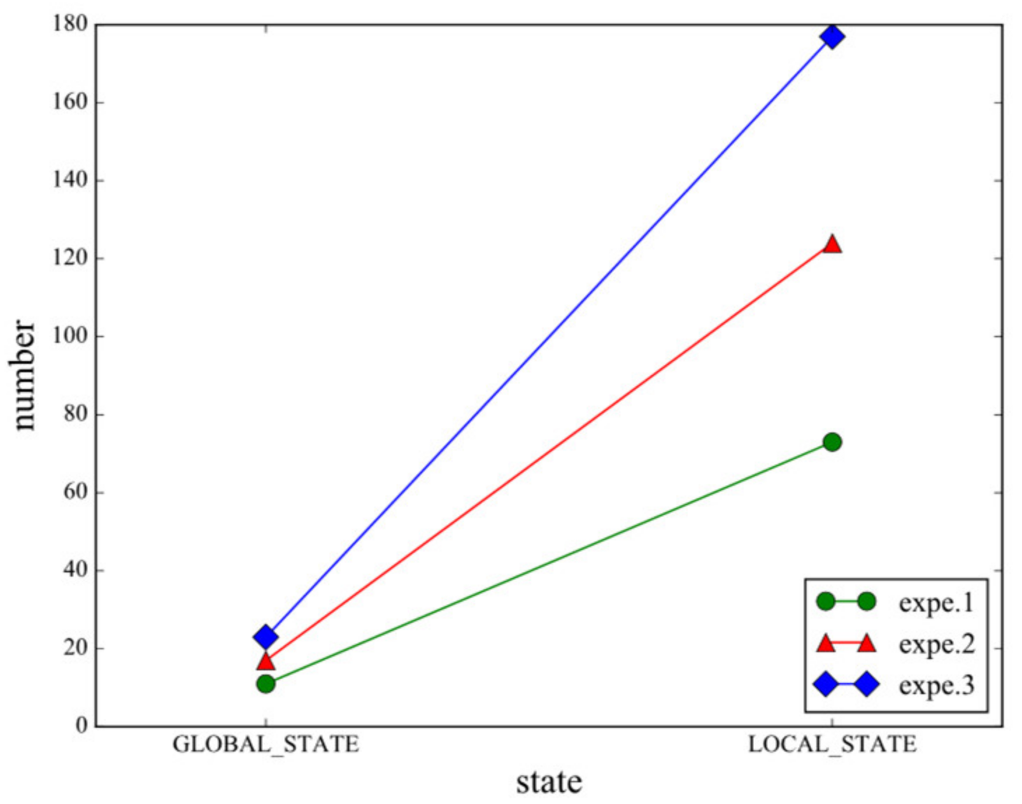
The first experiment contains three sets of sub-experiments, namely Experiment (1), Experiment (2) and Experiment (3). in Figure 8. In the experimental test, we used a CM to exchange data with multiple SMs to achieve high-precision time synchronization between nodes (the number of SMs can be seen in Figure 8). Affected by equipment factors, we tested up to 1 + 3. As shown in Figure 8, we tested the stay time of nodes in the intermediate state during the synchronization establishment process (that is, all nodes from the INTEGRATE state to the STABLE state). The experimental results show that with the increase in the number of nodes, the global state transition of the nodes does not change much. This is because of the star topology. In addition, the state transition conditions of the nodes are consistent with the description in the protocol. Therefore, DoubleDeck can be used as a design model to guide the realization of the control logic of the protocol. In addition, we also recorded the number of states experienced by all nodes during the experiment, as shown in Figure 9. The analysis result shows that as the number of nodes increases, the state transition becomes more and more complicated. Through the hierarchical state machine method, DoubleDeck can split a huge flat state machine to simplify the design and implementation of protocol control logic.
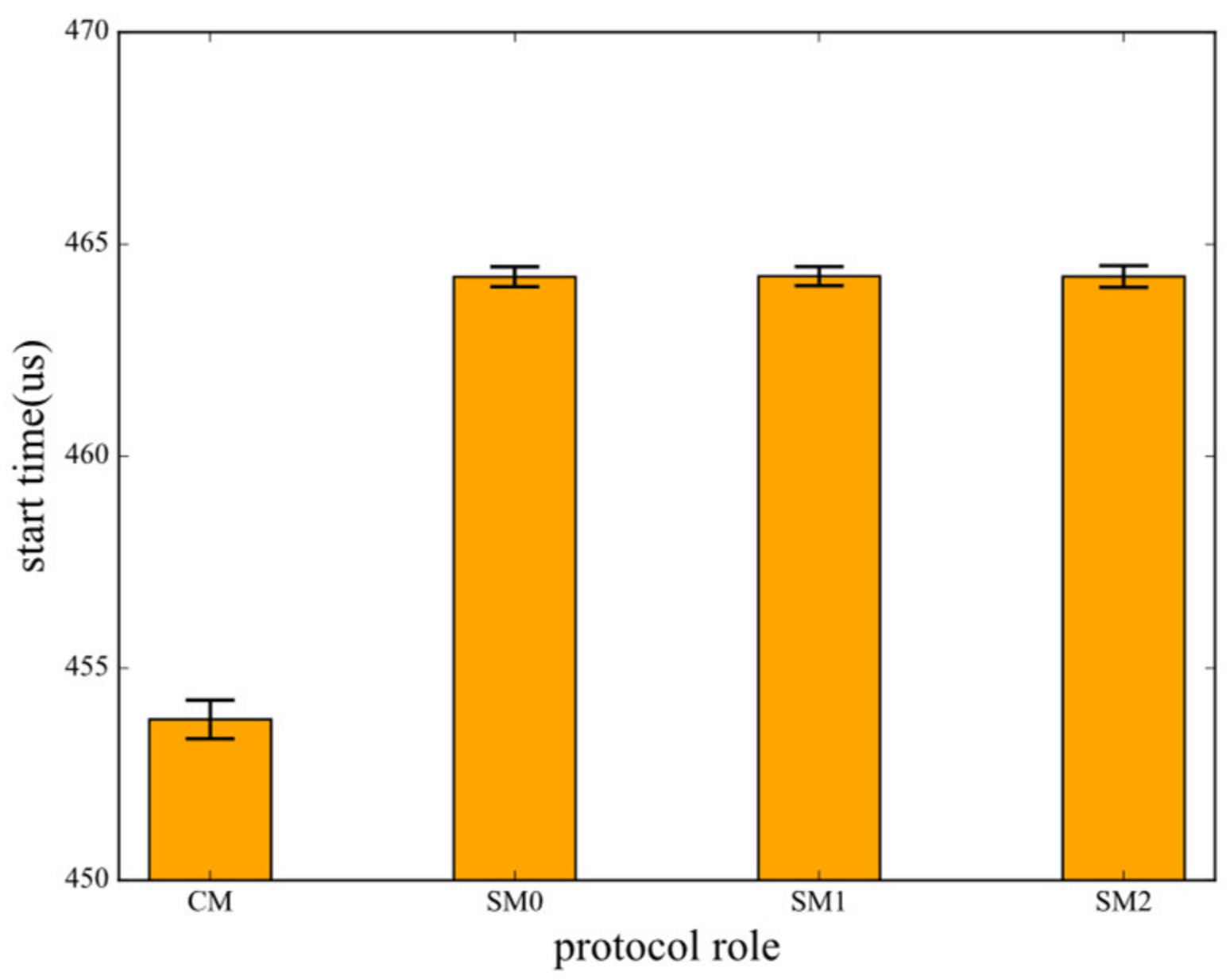
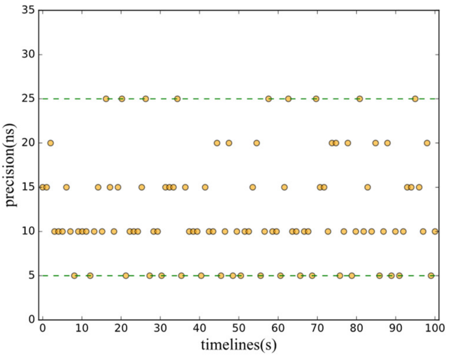
In the second experiment, we evaluated the performance of the AS6802 IP core using three SMs and one CM. First, we tested the synchronization establishment time (that is, the time required for all nodes from the INTEGRATE state to the SYNC state) many times. We carried out 12 sets of experiments and recorded the average results as shown in Figure 10. According to the results in Figure 10, we found that the test network can quickly synchronize the time of the entire network within 465 microseconds. After all nodes enter the SYNC state, we obtain the maximum clock deviation of the four nodes through an oscilloscope, that is, the synchronization accuracy of the test network. We collected 100 sets of data, as shown in Figure 11. Analyzing the experimental results, it can be found that the synchronization accuracy of the four nodes can be controlled within 25 ns, which fully meets the high-precision time synchronization requirements of TTE. Therefore, DoubleDeck can provide high performance while simplifying the design and implementation of the control logic of the protocol.
In this experiment, we first tested the maximum clock frequency of each module, and the lowest one was recorded as 126.26 MHz. Therefore, the clock frequency of system run is 125 MHz. We also evaluated and resourced utilization by Quartus 13.0 (Altera synthesis tool). Table 3 shows the result of resource utilization for the AS6802 IP core, including Slice Look-Up Tables (LUTs), Slice registers, Block memory. The FPGA chip has 367,180 Slice Look-Up Tables (Slice LUTs), 734,360 Slice registers, and 1431 M20K RAM Tiles (29,306,880b). The results show that the AS6802 IP core based on the DoubleDeck model accounts for very little hardware resource overhead of Altera Arria10. The logic unit accounts for 6.53% of the total logic unit (Slice LUTs), the register unit accounts for 2.93% of the total register unit, and the block memory resource accounts for 1.32% of the total block memory resource.

5.2. Evaluation for BDM Mechanism

We used Verilog as the programming language, based on the DoubleDeck model and BDM mechanism to achieve simplified AS6802, PTP [23] and TCP [24] protocol processing and control hardware code. At the same time, the implementation and testing of the AS6802 protocol are described in detail in Section 5.1. In the traditional protocol acceleration, a single state machine is used when the control logic is simple, and multiple state machines are used for complex cases. Each state machine is individually designed and implemented. We define these methods as traditional independent programming models. In order to test the feasibility of the patterned programming of the BDM mechanism, we compared the patterned programming method of the BDM mechanism with the traditional independent programming method of each state. The clock frequency of the FPGA we used was 125 MHz. After implementation, we tested the maximum clock frequency of each module, the lowest was 222.14 MHz (PTP) and 192.53 MHz (TCP proxy), which fully meets the timing requirements. As shown in Figure 12, the experimental results show that the processing control hardware logic based on the BDM mechanism writes the protocol to make full use of the advantages of model-driven programming, which can reduce the development effort of the staff. More detail and source codes are available at Github [25].
Drawing on the idea of model-driven programming [4], we implemented the programming template of the bottom state machine of the protocol based on the BDM mechanism. In the subsequent development process, you only need to modify the relevant parameters to quickly instantiate the hardware code of the sub-state machine corresponding to each global state. We used three protocol (AS6802, TCP and PTP) control state machines to test the traditional programming method using a single-layer finite state machine and the BDM mechanism based on the DoubleDeck model. Among them, the SM state machine of the AS6802 protocol, the state machine of the master clock of the PTP protocol, and the number of lines of code (LoC) of the server side of the TCP protocol are shown in Figure 12a. Combined with Figure 12b, we found that the amount of Verilog code that developers need to develop has been reduced by more than 30%, and the more complex the protocol, the better the results. Among them, the development of Verilog code of the most complex AS6802 protocol has been reduced by more than 50%. That is, DoubleDeck using the BDM mechanism can reduce the complexity of network protocol hardware control logic implementation, especially in the face of complex protocols.
DoubleDeck is a design and implementation method for control logic. In order to further verify the performance of DoubleDeck, we implemented the PTP module and the TCP proxy module based on the control logic of the PTP and TCP protocols.
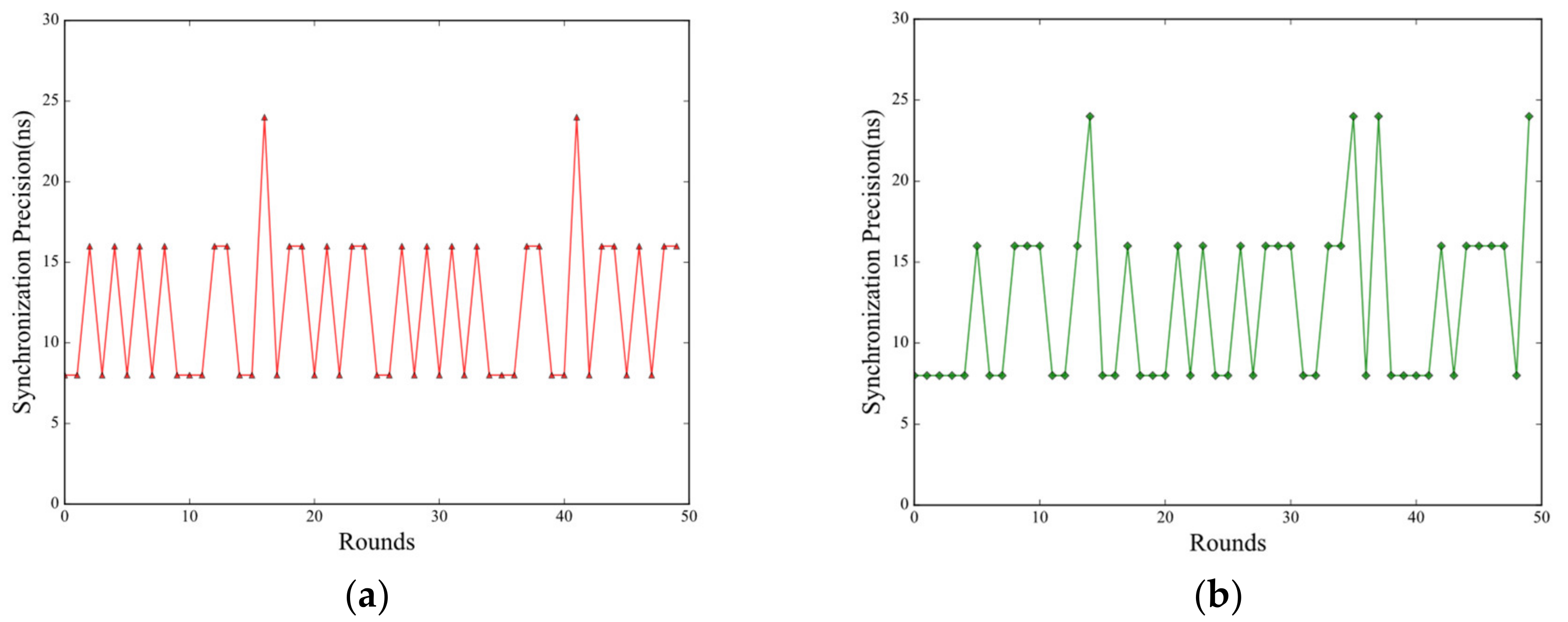
We deployed two kinds of PTP modules on the four FPGAs in Figure 6, and they formed a simple time synchronization network. The network time synchronization cycle is 100 ms, that is, every 100 ms all nodes exchange PTP packets to obtain the time deviation and adjust their respective times (register value). The network adopts a ring topology, so the clock deviation of two nodes separated by one node is selected as the synchronization precision of the network. We experimented with the PTP module implemented by two methods and recorded 50 sets of data. The results are shown in Figure 13. It can be found that the performance of the PTP module implemented by the two methods has similar performance. In addition, considering the periodic synchronization characteristics of the PTP protocol, throughput and delay are not important performance indicators for the PTP module.
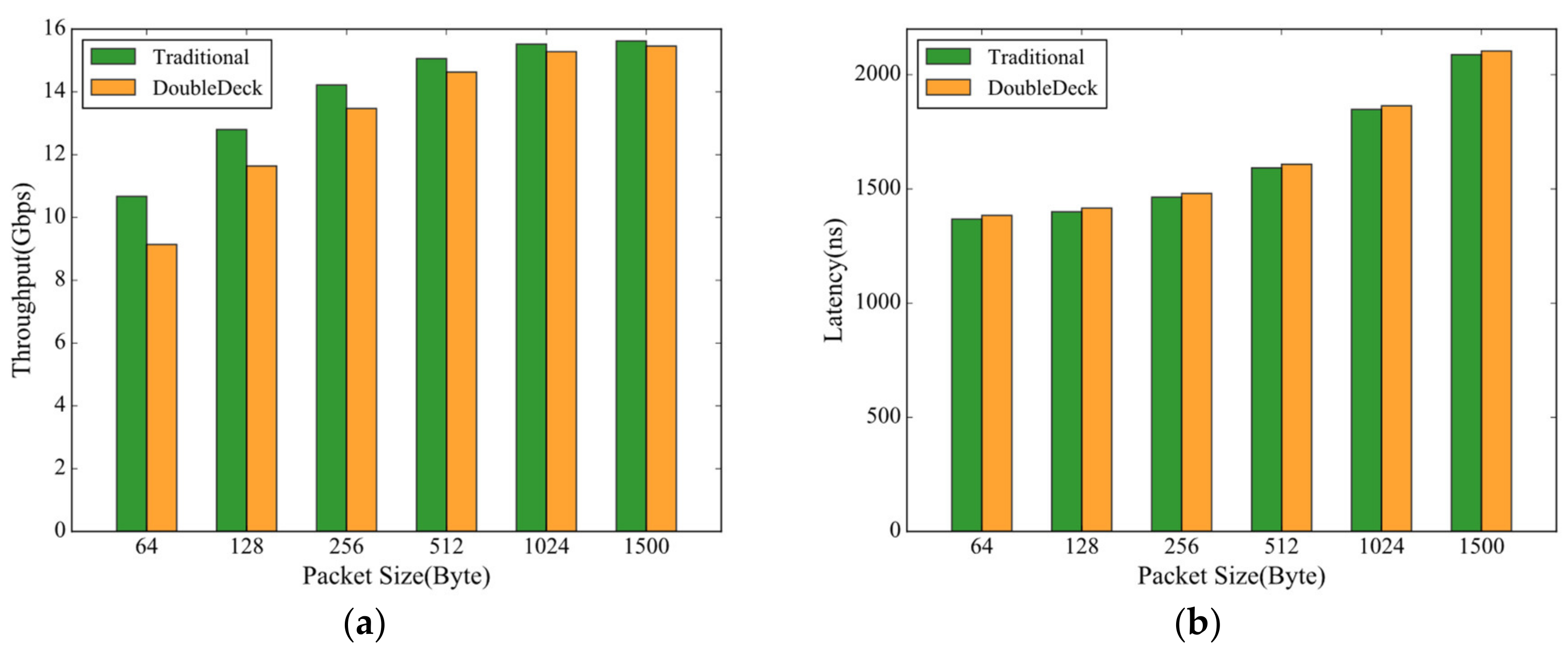
In order to compare the performance of and the TCP proxy based on traditional flat FSM and the DoubleDeck, we conducted a comparative experiment by interconnecting the FPGA with TCP proxy implemented by different methods and two hosts. According to the size of the data packets, the TCP proxy implemented by the two methods achieves a similar throughput (as shown in Figure 14a). In addition, as the size of the data packet increases, the difference in throughput of the two methods becomes smaller and smaller. This is an expected result, because the hierarchical management of DoubleDeck will bring additional communication overhead, resulting in a greater time cost of each data packet in TCP proxy based on DoubleDeck. However, because the additional overhead brought by the hierarchical management accounts for a relatively small percentage of the time overhead of the entire TCP proxy, the processing delays of the TCP proxy implemented by the two methods are similar, as shown in Figure 14b. Especially as the length of the message grows, the extra overhead becomes less important.
In addition, we used Quartus 13.0 (Altera synthesis tool) to evaluate the hardware resource consumption by the PTP module and the TCP proxy module, as shown in Table 4. Both protocol agents adopt a separate implementation architecture of control logic and processing logic, similar to Figure 7. The processing logic uses the same code. At the same time, the control logic adopts the traditional flat FSM and DoubleDeck, respectively. According to Table 4, it can be found that using DoubleDeck causes the control logic to use more hardware resources. This is an expected result because hierarchical management will bring additional hardware overhead. However, according to the data in the table, we can find that the increased hardware resources account for a small proportion of the total hardware resource consumption. All in all, DoubleDeck has greatly reduced the workload of developers by adding a small amount of communication overhead and hardware resource overhead.

6. Related Works

Deploying network protocols based on hardware can ensure that protocol entities have high processing performance and low processing latency. However, because hardware programming needs to consider data, structural conflicts, timing constraints and other issues, it is difficult to program and debug, and it is difficult to achieve rapid deployment of network protocols. To this end, related research [16] proposed to achieve efficient hardware programming based on the finite state machine model and its variants.
The finite state machine (FSM) model is widely used in hardware logic design [20]. It divides the complex control logic into a limited number of processing states, and triggers state-to-state transitions through events. However, when there are many protocol states and the triggering events of state transitions are complex, the flat finite state machine model will lead to the problems of long hardware implementation path and low comprehensive frequency of single functional logic. In addition, a variety of states and complex state transitions in control will cause difficulties in later debugging.
The Hierarchical Finite State Machine (HFSM) [19] adds elements such as state variables and state transitions on the basis of FSM to further express the dynamic behavior of the system at a finer granularity. The HFSM uses state variables to hierarchically manage a limited number of states and uses a top-down approach to describe the system. In this method, the hardware logic is divided into multiple smaller sub-modules, which can reduce the complexity of the overall hardware design. However, the sub-modules are highly independent and need to be designed and tested separately, and the difficulty of later debugging is increased to a certain extent.
In order to reduce the difficulty of programming and debugging, there have recently been studies using high-level integrated systems (HLS) [26] or domain-specific languages (P4, etc.) [27] to deploy network protocols and related functions. However, these hardware logics based on high-level programming languages have the problems of large resource overheads and low processing performance [28], and it is difficult to meet the processing requirements of high-speed networks.

7. Conclusions

Hardware-accelerated software protocol processing is one of the current research hotspots in the field of networks and distributed systems. However, the traditional finite state machine model find it difficult to solve the complexity problem of hardware implementation of complex protocol control logic. Although the hierarchical method has become an important means to simplify the design of complex logic, the existing work fails to provide developers with a standard for dividing complex protocol control logic. This paper decouples the control logic of the protocol into conversion logic and processing logic and maps it to the double-layer state machine of the DoubleDeck model, which effectively simplifies the design of complex protocol control logic. In addition, this article also designed a model programming mechanism—BDM. BDM provides programming templates for the programming of partial state machines, which effectively reduces the workload of developers.

Author Contributions

Conceptualization, Y.Y. and Z.S.; Methodology, Y.Y. and Z.S.; Hardware and software, Y.Y. and W.F.; Validation, Y.Y, L.T. and Z.S.; Investigation, W.F. and J.Y.; Writing—original draft preparation, Y.Y.; Writing—review and editing, Y.Y. and Z.S.; Funding acquisition, Z.S. All authors have read and agreed to the published version of the manuscript.

Funding

This work was supported by National Natural Science Foundation of China (91938301). And this work was sponsored by Zhejiang Lab (NO. 2020LE0AB01).

Acknowledgments

We would like to thank the anonymous reviewers for their valuable feedback. We also thanks HuNan Hua Xin Tong Networks for their equipment to carry out our experiments.

Conflicts of Interest

The authors declare no conflict of interest.

References

  1. Segall, A. Distributed network protocols. IEEE Trans. Inf. Theory 1983, 29, 23–35. [Google Scholar] [CrossRef]
  2. Yi, Y.; Wei, Q.; Jin, L.Y.; Lu, T.; Zhi, G.S. A hierarchical model of control logic for simplifying complex networks protocol design. In Proceedings of the 17th Annual IFIP International Conference on Network and Parallel Computing, Zhengzhou, China, 28–30 September 2020. [Google Scholar]
  3. Jamshed, M.A.; Moon, Y.; Kim, D.; Han, D.; Park, K. MOS: A reusable networking stack for flow monitoring middleboxes. In Proceedings of the 14th {USENIX} Symposium on Networked Systems Design and Implementation ({NSDI} 17), Boston, MA, USA, 27–29 March 2017; pp. 113–129. [Google Scholar]
  4. Li, J.; Sun, Z.; Yan, J.; Yang, X.; Jiang, Y.; Quan, W. DrawerPipe: A Reconfigurable Pipeline for Network Processing on FPGA-Based SmartNIC. Electronics 2020, 9, 59. [Google Scholar] [CrossRef] [Green Version]
  5. Pfaff, B.; Pettit, J.; Koponen, T.; Jackson, E.; Zhou, A.; Rajahalme, J.; Gross, J.; Wang, A.; Stringer, J.; Shelar, P.; et al. The design and implementation of open vswitch. In Proceedings of the 12th {USENIX} Symposium on Networked Systems Design and Implementation ({NSDI} 15), Oakland, CA, USA, 4–6 May 2015; pp. 117–130. [Google Scholar]
  6. Kotulski, Z.; Nowak, T.W.; Sepczuk, M.; Tunia, M.A. 5G networks: Types of isolation and their parameters in RAN and CN slices. Comput. Netw. 2020, 171, 107135. [Google Scholar] [CrossRef]
  7. Nasrallah, A.; Thyagaturu, A.S.; Alharbi, Z.; Wang, C.; Shao, X.; Reisslein, M.; ElBakoury, H. Ultra-low latency (ULL) networks: The IEEE TSN and IETF DetNet standards and related 5G ULL Research. IEEE Commun. Surv. Tutor. 2018, 21, 88–145. [Google Scholar] [CrossRef] [Green Version]
  8. Nasrallah, A.; Thyagaturu, A.S.; Alharbi, Z.; Wang, C.; Shao, X.; Reisslein, M.; Elbakoury, H. Performance comparison of IEEE 802.1 TSN time aware shaper (TAS) and asynchronous traffic shaper (ATS). IEEE Access 2019, 7, 44165–44181. [Google Scholar] [CrossRef]
  9. Gandhi, R.; Liu, H.H.; Hu, Y.C.; Lu, G.; Padhye, J.; Yuan, L.; Zhang, M. Duet: Cloud scale load balancing with hardware and software. ACM SIGCOMM Comput. Commun. Rev. 2014, 44, 27–38. [Google Scholar] [CrossRef]
  10. Hong, C.Y.; Caesar, M.; Godfrey, P.B. Finishing flows quickly with preemptive scheduling. ACM SIGCOMM Comput. Commun. Rev. 2012, 42, 127–138. [Google Scholar] [CrossRef]
  11. Firestone, D. {VFP}: A Virtual Switch Platform for Host {SDN} in the Public Cloud. In Proceedings of the 14th {USENIX} Symposium on Networked Systems Design and Implementation ({NSDI} 17), Boston, MA, USA, 27–29 March 2017; pp. 315–328. [Google Scholar]
  12. Firestone, D.; Putnam, A.; Mundkur, S.; Chiou, D.; Dabagh, A.; Andrewartha, M.; Angepat, H.; Bhanu, V.; Caulfield, A.; Chung, E.; et al. Azure accelerated networking: SmartNICs in the public cloud. In Proceedings of the 15th {USENIX} Symposium on Networked Systems Design and Implementation ({NSDI} 18), Renton, WA, USA, 9–11 April 2018; pp. 51–66. [Google Scholar]
  13. Weaver, N.; Paxson, V.; Gonzalez, J.M. The shunt: An FPGA-based accelerator for network intrusion prevention. In Proceedings of the 2007 ACM/SIGDA 15th International Symposium on Field Programmable Gate Arrays, Monterey, CA, USA, 18–20 February 2007; pp. 199–206. [Google Scholar]
  14. Kundel, R.; Burkert, T.; Griwodz, C.; Koldehofe, B. Chaining of hardware accelerated Virtual Network Functions in PCIe Environments. In Proceedings of the 20th International Middleware Conference Demos and Posters, Davis, CA, USA, 9–13 December 2019; pp. 13–14. [Google Scholar]
  15. Steinhammer, K.; Ademaj, A. Hardware implementation of the Time-Triggered Ethernet controller. In Embedded System Design: Topics, Techniques and Trends; Springer: Berlin/Heidelberg, Germany, 2007; pp. 325–338. [Google Scholar]
  16. Qi, Y.; Zhong, J.; Jiang, R.; Jia, Y.; Li, A.; Huang, L.; Han, W. FSM-Based Cyber Security Status Analysis Method. In Proceedings of the 2019 IEEE Fourth International Conference on Data Science in Cyberspace (DSC), Hangzhou, China, 23–25 June 2019; IEEE: New York, NY, USA, 2019; pp. 510–515. [Google Scholar]
  17. Moshref, M.; Bhargava, A.; Gupta, A.; Yu, M.; Govindan, R. Flow-level state transition as a new switch primitive for SDN. In Proceedings of the Third Workshop on Hot Topics in Software Defined Networking, Chicago, IL, USA, 17–22 August 2014; pp. 61–66. [Google Scholar]
  18. Lamport, L.; Malkhi, D.; Zhou, L. Reconfiguring a state machine. ACM SIGACT News 2010, 41, 63–73. [Google Scholar] [CrossRef]
  19. Fragal, V.H.; Simao, A.; Mousavi, M.R. Hierarchical featured state machines. Sci. Comput. Program. 2019, 171, 67–88. [Google Scholar] [CrossRef] [Green Version]
  20. Oliveira, A.; Melo, A.; Sklyarov, V. Specification, Implementation and Testing of HFSMs in Dynamically Reconfigurable FPGAs. International Workshop on Field Programmable Logic and Applications; Springer: Berlin/Heidelberg, Germany, 1999; pp. 313–322. [Google Scholar]
  21. Kopetz, H.; Ademaj, A.; Grillinger, P.; Steinhammer, K. The time-triggered ethernet (TTE) design. In Proceedings of the Eighth IEEE International Symposium on Object-Oriented Real-Time Distributed Computing (ISORC’05), Seattle, WA, USA, 18–20 May 2005; IEEE: Piscataway, NJ, USA, 2005; pp. 22–33. [Google Scholar]
  22. HuNan Hua Xin Tong Networks. AS6802 Core. Available online: https://gitee.com/huaxintong/as6802_core (accessed on 10 September 2020).
  23. Eidson, C.; Fischer, M.; White, J. IEEE-1588™ Standard for a precision clock synchronization protocol for networked measurement and control systems. In Proceedings of the 34th Annual Precise Time and Time Interval Systems and Applications Meeting, Reston, VA, USA, 3–5 December 2002; pp. 243–254. [Google Scholar]
  24. Fall, K.R.; Stevens, W.R. The Protocols. In TCP/IP Illustrated; Addison-Wesley: Boston, MA, USA, 2011; Volume 1. [Google Scholar]
  25. National University of Defense Technology. Available online: https://gitee.com/opentsn/openTSN (accessed on 10 September 2020).
  26. Ullah, S.; Choi, J.; Oh, H. IPsec for high speed network links: Performance analysis and enhancements. Future Gener. Comput. Syst. 2020, 107, 112–125. [Google Scholar] [CrossRef]
  27. Wang, L.; Cheng, R.; Lee, S.D.; Cheung, D. Accelerating probabilistic frequent itemset mining: A model-based approach. In Proceedings of the 19th ACM International Conference on Information and Knowledge Management, New York, NY, USA, 26–30 October 2010; pp. 429–438. [Google Scholar]
  28. Bosshart, P.; Daly, D.; Gibb, G.; Izzard, M.; McKeown, N.; Rexford, J.; Schlesinger, C.; Talayco, D.; Vahdat, A.; Varghese, G.; et al. P4: Programming protocol-independent packet processors. ACM SIGCOMM Comput. Commun. Rev. 2014, 44, 87–95. [Google Scholar] [CrossRef]
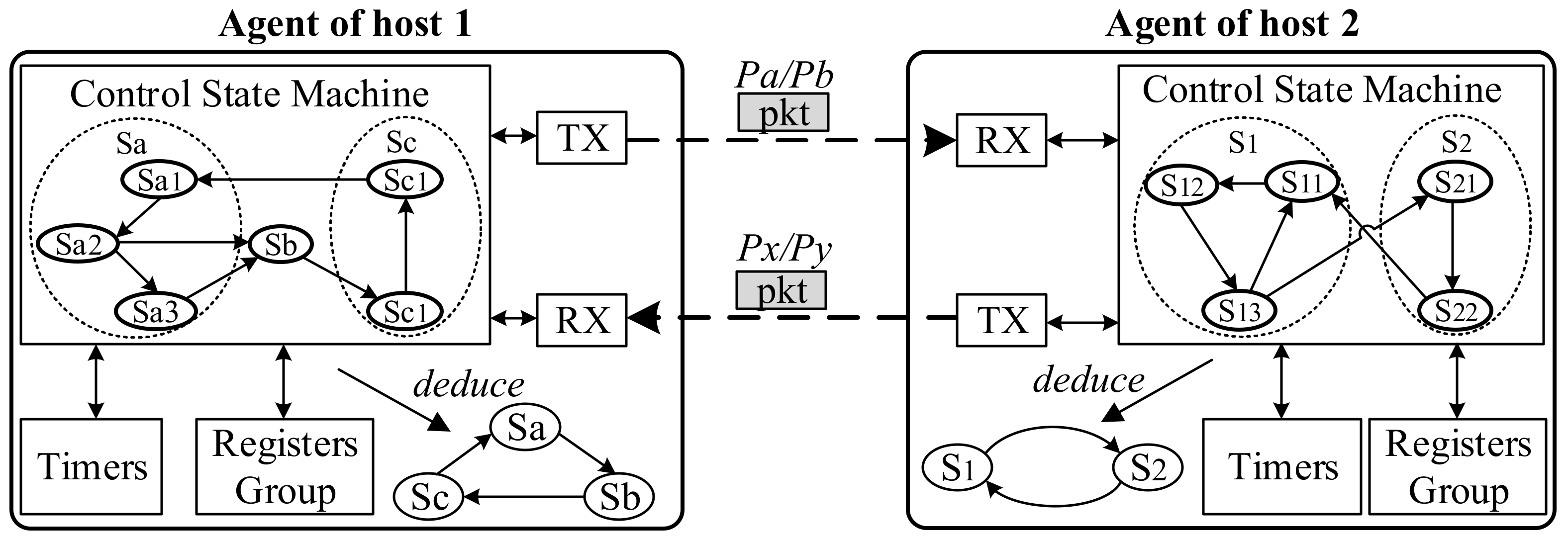
Figure 1. Example of a network protocol.
Electronics 09 01647 g001
Figure 2. Comparison of the two states. (a) Schematic diagram of the global state. (b) Schematic diagram of the local state.
Electronics 09 01647 g002
Figure 3. The DoubleDeck model consists of top SM and bottom SMs. SM is an abbreviation of State Machine. The state in the top SM is the externally visible global state. The state in bottom SMs is a local state that is not visible from the outside.
Electronics 09 01647 g003
Figure 4. The overview of bottom deck mapping mechanism.
Electronics 09 01647 g004
Figure 5. The hardware design of DoubleDeck.
Electronics 09 01647 g005
Figure 6. An experiment environment with 4 nodes (FPGAs).
Electronics 09 01647 g006
Figure 7. The implementation of the AS6802 IP core.
Electronics 09 01647 g007
Figure 8. The time used by the nodes during the startup phase.
Electronics 09 01647 g008
Figure 9. The number of global and local states of nodes in the three experiments.
Electronics 09 01647 g009
Figure 10. The start-up time of the network.
Electronics 09 01647 g010
Figure 11. Synchronization precision of the four-node network.
Electronics 09 01647 g011
Figure 12. Comparison result between traditional method and DoubleDeck method. (a) Code amount; (b) the percentage of code reduction.
Electronics 09 01647 g012
Figure 13. The synchronization precision of network comparison between traditional finite state machine (FSM) method and DoubleDeck method. (a) Traditional FSM method; (b) DoubleDeck method.
Electronics 09 01647 g013
Figure 14. The performance comparison between traditional FSM method and DoubleDeck method. (a) Throughput comparison; (b) latency comparison.
Electronics 09 01647 g014
Table 1. State transition table for the agent of host 2. The state transition table details the transition details of the control state machine.
StateGuardNext StateCommand
RX PacketTimer T1Register Local_tTX PacketTimer T1Register Local_t
S1(S11)PaNo timeout-S1(S12)-T1++0
S1(S12)-Timeout-S1(S13)Px0local_t++
S1(S13)PbNo timeout-S2(S21)-T1++local_t++
S2(S21)--t0S2(S22)Py-local_t++
S2(S22)Pa-<t0S1(S11)--local_t++
Table 2. The number of local states (LS) corresponding to the global state in the AS6802 IP core.
Global StateNum(LS)Global StateNum(LS)Global StateNum(LS)
SM_INTEGRATE4SM_SYNC9CM_WAIT2
SM_UNSYNC6SM_STABLE7CM_SYNC6
SM_FLOOD5CM_INTEGRATE2CM_STABLE5
SM_START3CM_UNSYNC3--
SM_TENTATIVE8CM_ENABLED1--
Table 3. Resource usage comparation based on Altera 10.
AS6802 IPFPGAPercentage
Slice LUTs23,982367,1806.53%
Slice Registers21,516734,3602.93%
Block Memory387,10429,306,8801.32%
Table 4. The resource consumption of key modules in PTP and TCP proxy.
ModuleSubmoduleSlice LUTsSlice RegistersBlock Memory
PTPControl logic (DoubleDeck)1822873983
Control logic (Traditional)1122312393
Processing logic3740469256,203
TCP proxyControl logic (DoubleDeck)112983428
Control logic (Traditional)71462234
Processing logic961133413,532
Publisher’s Note: MDPI stays neutral with regard to jurisdictional claims in published maps and institutional affiliations.