Article

Impact of Tolerances on the Cogging Torque of Tooth-Coil-Winding PMSMs with Modular Stator Core by Means of Efficient Superposition Technique

1
Escuela de Ingeniería Eléctrica, Pontificia Universidad Católica de Valparaíso, Valparaíso 2362804, Chile
2
Department of Electrical Drives and Power Electronics, Johannes Kepler University Linz, 4040 Linz, Austria
3
Department of Electrical Engineering, University of Concepcion, Concepcion 4070386, Chile
4
Department of Electronic and Electrical Engineering, University of Sheffield, Sheffield S1 3JD, UK
*
Author to whom correspondence should be addressed.
Electronics 2020, 9(10), 1594; https://doi.org/10.3390/electronics9101594
Submission received: 9 September 2020 / Revised: 24 September 2020 / Accepted: 26 September 2020 / Published: 29 September 2020
(This article belongs to the Special Issue Analysis and Optimal Design Method for Electric Machine and Devices)

Abstract

:
This paper analyzes the impact of manufacturing tolerances on the cogging torque of a 24-slot 28-pole tooth-coil-winding permanent magnet synchronous machine with a modular stator core (TCW-MPMSM). Dimensional tolerances and asymmetries associated with the modular topology are studied by means of finite element simulations in order to identify key parameters that increase the cogging torque above the expected values of a faultless machine. Among five selected dimensional parameters, it was found that angular displacement, radial displacement, and tooth–tip width deviations of the stator segments have the most significant impact on the cogging torque. Considering these three key parameters, a full-range tolerance analysis is carried out by means of a proposed superposition-based approach, evaluating all possible combinations of typical deviation values. It is concluded that the cogging torque increment, generated by tolerances, is relatively independent of the faultless tooth–tip width of the stator segments and the arc-to-pole ratio. Robustness of the TCW-MPMSM, regarding cogging torque generation, depends on both the tightness of the tolerances handled in the manufacturing process and the rated cogging torque: the lower the cogging torque of the ideal machine, the less robust is the machine and, therefore, manufacturing imperfections will be required to be tightened.

1. Introduction

Tooth-coil-winding (TCW) permanent magnet (PM) machines with a modular stator core have been widely investigated in recent decades, given that they offer unique manufacturing attributes, which allow the design of complex structures [1,2,3,4]. These machines are characterized by having a segmented stator core with flux barriers between adjacent segments, as shown in Figure 1.
A segmented core can be used in flux-switching PM machines to allocate the magnets, resulting in a simple and robust rotor structure [5]. The modular structure is suitable for permanent magnet synchronous machines (PMSMs), since it simplifies the winding process, increases the slot fill factor and reduces the material waste produced during the manufacturing process of the stator laminations [6]. The modular stator is also suitable in applications where fault-tolerant capability is required, as this topology reduces the magnetic and electric coupling of coils of adjacent modules [7,8].
Depending on the geometry, the modular stator structure can be classified as either an I-shape [9], E-shape, or U-shape [10] (also called a C-shape). The I-shape stator core is commonly used in yokeless and segmented armature (YASA) axial flux permanent magnet machines [9], whereas the E-shape and the U-shape structures are typically adopted in radial flux topologies.
Flux barriers (flux gaps) in the stator core can increase the reluctance of the magnetic circuit, which, in turn, decreases the magnetic coupling between stator and rotor when compared to a traditional stator structure (without the flux barrier). This can lead to a potentially lower constructive volume utilization [7]. Despite this, flux barriers can have a positive effect on the machine performance, by reducing sub- or super-space-harmonics of the on-load airgap flux density distribution generated by the TCW [11].
Several papers have studied the performance optimization of these machines [10,11,12,13]. In most cases, the constructive aspects are not thoroughly considered, and the geometry of the machine is evaluated with exact dimensions. However, due to assembly imperfections and mechanical tolerances of constructive parameters, the machine prototype may differ from the theoretical (faultless) design. Neither robust designing nor tolerance analyses of TCW-PMSMs with modular stators have yet been addressed in literature, even when these two aspects have been proven to be relevant to modern electrical machine design [13].
Tolerance analysis involves dimensional, assembly and material imperfections, and their impact on the machine performance [14]. For instance, in conventional TCW-PMSMs, assembly tolerances such as magnet misalignment affect both the period and the peak-to-peak value of the cogging torque [15]. Dimensional tolerances also modify the back electromotive force which can generate circulating currents in the stator windings [16,17]. Similar effects are obtained when the PMs feature different magnetization values [18]. Among the evaluated performance indexes for PMSMs, cogging torque and torque ripple are critical [15,16,18], as it mainly depends on the geometry of the magnets and slots, which are subjected to manufacturing imperfections.
In order to avoid unexpected effects of tolerances on the performance of a final prototype, a sensitivity analysis and a robustness study should be carried out [13,19]. As mechanical imperfections originate from different sources and combinations of parameters, finite element (FE) analysis can take considerable time; in this case, analytical or semi-analytical methods are preferred [20,21,22,23].
The classical approach to robust design considers inevitable parameter variation, aiming to trade off rated performance versus robustness. Figure 2 shows a simple optimization (maximization) decision of a target y that depends on the parameter x. The optimal solution is not robust, as a slight change of the parameter x results in a large loss of y value, whilst the robust solution does not have this deficiency. This concept has not been evaluated for TCW-PMSMs with modular stator core (TCW-MPMSM) so far.
This paper aims to determine the impact that dimensional and assembly tolerances of the stator structure have on the cogging torque of TCW-MPMSM, and to state general conclusions about the robustness of these machines, regarding the cogging torque. A set of relevant parameters will be defined for this analysis, such as tooth–tip dimension, module dimension and module displacement.
The paper is organized as follows. In Section 2, the topology and five selected variables to be subjected to analysis are described. In Section 3, the five different parameters subjected to tolerance are evaluated, considering a single module of a 24-slot 28-pole TCW-MPMSM, by means of bidimensional (2-D) FE simulations. In Section 4, a comprehensive analysis of combinations of dimensional and assembly tolerances is carried out on all the modules of a 24-slot 28-pole machine, by means of a novel semi-analytical method based on superposition techniques. The proposed method makes the full-range evaluation process feasible, significantly decreasing the computation burden and showing excellent accuracy when compared with finite element analysis (FEA). Finally, Section 5 presents the conclusions and future research possibilities.

2. Topology and Variables Subjected to Analysis

In order to maximize the flux linkage in a TCW-PMSM with a modular stator, it is recommended to choose the number of slots (Qs) close to the number of poles (2p) [7]. Typical configurations can be determined by
Q s = 2 p ± d ,
where d is an integer equal to Q s /6 [7]. In this section, a 24-slot 28-pole outer-rotor machine is analyzed, which was previously optimized with focus on the full-load electromagnetic torque mean value [10]. Tooth tips are included to increase the flux linkage and, consequently, to enlarge the back electromotive force (back-EMF) and the electromagnetic torque. For the 24-slot 28-pole machine, Q s < 2 p holds. For topologies satisfying this condition, the airgap between the modules increases the average torque [12] and, therefore, tooth tips should point towards the slot (towards the module symmetry axis) and not towards the flux gaps between modules. Main design parameters of the machine are schematized in Figure 3 and grouped in Table 1.
Displacement and dimensional tolerances of modular components (e.g., PMs), as well as tooth–tip tolerances, impact on the performance of conventional PMSMs [14,15]. In TCW-MPMSMs, fins and matches are designed in the mounting frame to assemble modular segments [6]. Both the manufacturing of these elements and the assembly process may be subjected to tolerances and, therefore, stator segment defects could affect the TCW-MPMSM cogging torque. Hence, the parameters subjected to tolerance analysis in this paper have tolerances associated with modularity: angular displacement of the modules ( α M) and radial displacement of the modules ( r M); and more commonly found tolerances in conventional PMSMs: the tooth–tip width (btt), tooth–tip height (htt) and tooth width (bt). These dimensional tolerances (Δ) are shown in Figure 4.
Given the novelty of TCW-MPMSM, clear tolerance values for their manufacturing do not exist so far. Hence, in this paper the lowest dimensional tolerance considered is 0.1 mm, typical of laser cutting machining [24], and the highest is 1.5 mm (15 times the typical tolerance value).

3. Results of Tolerance Analysis on a Single Module of TCW-MPMSM

Tolerance analysis is performed on a 24-slot 28-pole TCW-MPMSM, considering the design parameters shown in Table 1, and results that were presented in a previous conference publication [10]: a tooth–tip width of 6 mm and pole-to-arc ratio of 0.9 should be adopted in the machine. These values maximize the machine’s output torque.
The impact of the angular displacement of the modules on the performance of the selected machine is analyzed by introducing an offset angle Δ α M in a single module. Specifically, four offset angles are evaluated: 0.05°, 0.25°, 0.5° and 0.75°, which translate into tangential displacements of the modules of 0.1, 0.5, 1.0 and 1.5 mm, respectively (one, five, ten and fifteen times the typical tolerance found in laser cutting, respectively). The comparison of the cogging torque obtained when these tolerances are adopted versus the nominal case (Δ α M = 0) is shown in Figure 5 for the 24-slot 28-pole machine, considering both (a) the waveform and (b) the spectrum.
From Figure 5a, it is possible to appreciate that the angular displacement of a single module significatively affects the cogging torque amplitude and waveform, whilst from the spectrum analysis shown in Figure 5b it is observed that the angular displacement of a single module also affects the period of the cogging torque, which is in agreement with results found in [25].
The order of each non-zero harmonic, regarding a mechanical rotor rotation, is a multiple of the pole numbers. This occurs since the period of the cogging torque depends on the periodicity of rotor and stator: a certain number of identical portions into which each structure can be subdivided. The native harmonic components (NHC) of cogging torque are defined as [25]:
N N H C , k = k · lcm ( t s , t p ) ,
where lcm is the least common multiple between the periodicity of the stator (ts) and the periodicity of the rotor (tp), and k is an integer number (k = 1, 2, 3…∞). For the nominal case, ts = Qs/2 and tp = 2p. However, when a single module is shifted from its symmetry position, the stator periodicity is lost and therefore ts = 1 and tr = 2p. The fundamental harmonic order is obtained with k = 1, thus, N N H C , 1 = 28 for the selected 28-pole machine.
From Figure 5, it can be noted that the increment of the cogging torque is approximately linear with respect to the angular displacement. This is further analyzed in Figure 6, which shows, for different tolerance values, the cogging torque increment of faulty cases when compared with the nominal case. The torque increment for negative angular displacement is the same as found for positive displacement, given the symmetry of the fault.
The impact of the radial displacement of modules on the machine performance is analyzed by introducing an offset Δ r M in a single module. The variation of the cogging torque due to this tolerance is shown in Figure 7a for positive deviations (0.1, 0.5, 1.0 and 1.5 mm), and in Figure 7b for negative deviations (−0.1, −0.5, −1.0 and −1.5 mm).
It can be seen, for both cases (negative and positive deviations), that the cogging torque increases and the waveform is altered, but to a lesser extent than the previous case (angular displacement). Moreover, both positive and negative deviations seem to increase the cogging torque to a similar extent. This can be seen through the numerical increase of cogging torque peak-to-peak value of faulty scenarios when compared with the nominal value, as shown in Figure 8.
On the other hand, Figure 9a–c shows the difference between the cogging torque peak-to-peak values between faulty cases and the nominal case for the tooth–tip length tolerance, tooth–tip height tolerance and tooth width tolerance, respectively.
From Figure 9a, it can be noted that tooth–tip width tolerance increases the cogging torque to a lesser extent than the angular displacement of the modules, similar to the tolerance changes for the radial displacement. This torque increment is significant, and it should be further analyzed.
From Figure 9b, it can be seen that tooth width tolerance has a minor impact in terms of additional cogging torque when compared to the other parameters, therefore it is not considered relevant enough to be subjected to further analysis. In addition, in Figure 9c, it is appreciated that positive deviations of the tooth–tip height practically do not affect the cogging torque peak-to-peak value, while negative deviations show a small cogging–torque increase. This can be explained by analyzing the dimensions of the tooth tips: when the height decreases, the tooth–tip ferromagnetic material operates in saturation, which translates into a shorter equivalent tooth–tip accordingly, as relative permeability decreases. For instance, when 15 times the typical tolerance is considered (negative deviation), the tooth–tip height changes from 2.0 to 0.5 mm, thereby drastically increasing the saturation of the tooth–tip and decreasing the equivalent width of the tooth–tip. Thus, cogging torque increases in agreement with the behavior found in Figure 7.
It is therefore recommended, in the design stage of these machines, to include saturation into the tolerance analysis when tooth–tip height is evaluated, since deviation values with similar magnitude order to the tooth–tip height can generate a significant increment in the cogging torque.
In summary, three of the five presented and studied parameters significantly affect the cogging torque peak-to-peak value: angular displacement of the modules (Figure 6), radial displacement of the modules (Figure 8), and the tooth–tip width (Figure 9a).

4. Full-Range Tolerance Analysis and Robustness Evaluation of TCW-MPMSM

When a constructive parameter of the modules of TCW-MPMSMs is subjected to tolerance analysis, more than a single module should be taken into account to obtain comprehensive conclusions. In a real manufacturing process, multiple modules can exhibit failures (and combinations of them) and therefore a deeper analysis is required. For a single parameter subjected to analysis, when n failures are considered in addition to the faultless condition, a total of n + 1 possible combinations in a single module must be studied. This holds true for a discrete tolerance analysis. For instance, considering the lowest dimensional tolerance for the angular displacement, each module can be either centered (faultless), displaced 0.05° clockwise or displaced 0.05° counter-clockwise regarding its axis of symmetry, which sums up three combinations to be evaluated and two possible failures ( n = 2 ) for each stator segment.
For the topology under analysis, which has Qs/2 modules, the number of possible combinations which require to be evaluated is:
n eval = ( n + 1 ) Q s / 2
Hence, to analyze a single dimensional tolerance (e.g., angular displacement of modules) regarding all modules of the selected 24-slot machine, the model must be evaluated roughly 4000 times in presence of one failure per module (n = 1) and 500,000 times in case of two failures per module (n = 2), which is infeasible by means of FE simulations only.
Therefore, in order to analyze the effect of all the possible combinations of faulty modules over TCW-MPMSMs in a short frame time, a method based on the superposition techniques stated in [23,26] is proposed. These techniques are used to reconstruct the cogging torque waveform considering the contribution of a single pole-pair (in some cases, even a single magnet or a single slot).

4.1. Superposition Method

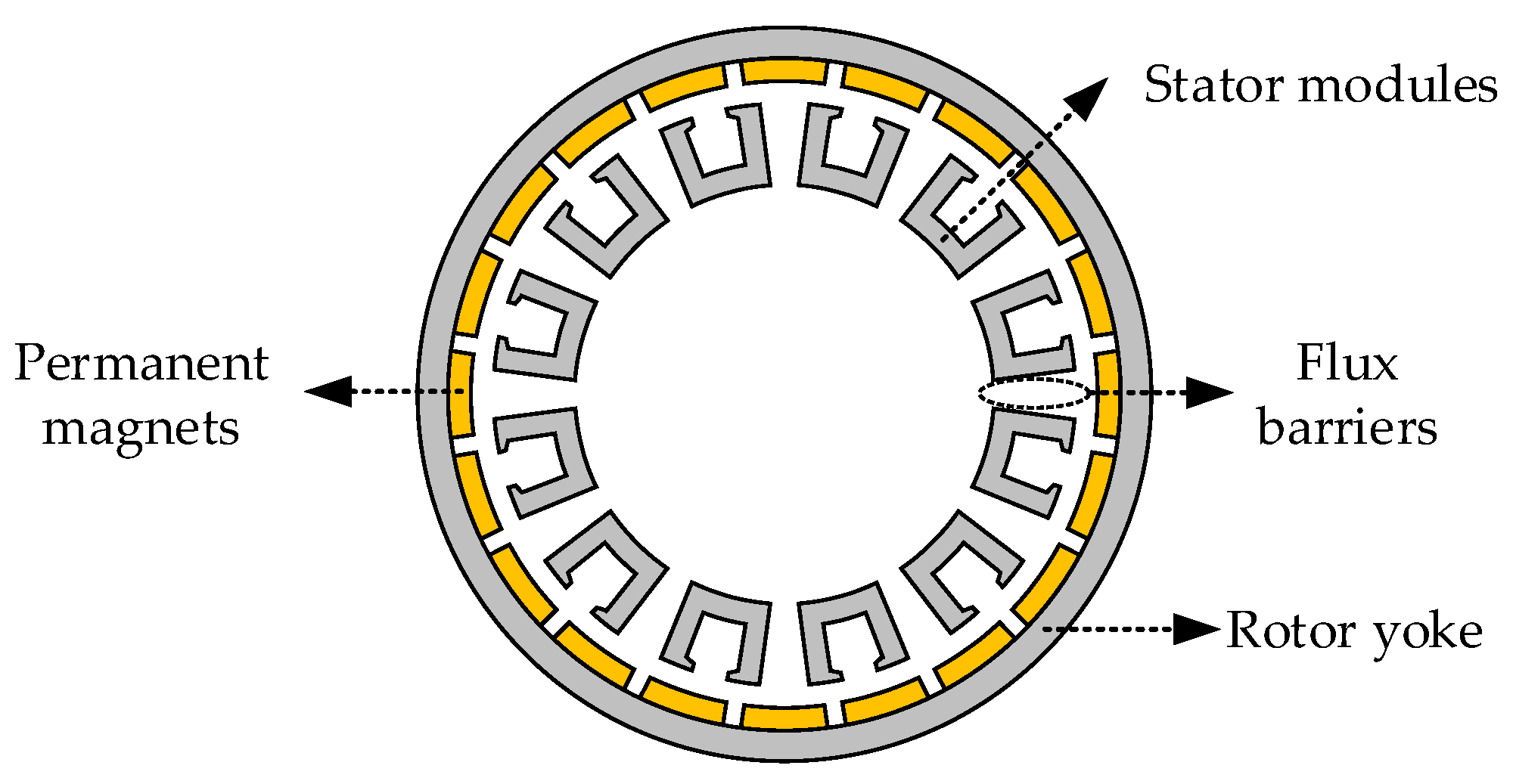
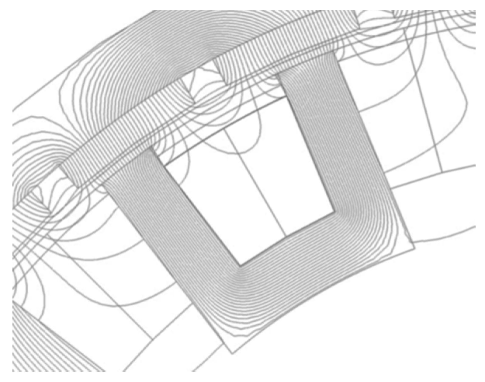
For TCW-MPMSMs with the number of slots given by (1), modules are ideally magnetically decoupled from each other, as depicted in Figure 10, which shows the no-load flux lines of a 24-slot 28-pole machine.
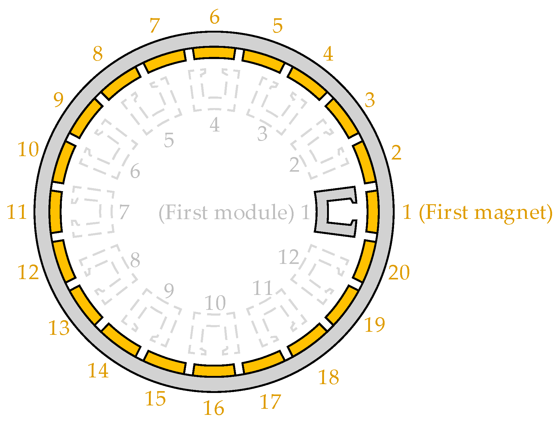
A negligible number of magnetic field lines link two or more modules, while most of the lines close the magnetic circuit through a single module. Hence, the overall cogging torque can be synthesized considering the contribution of each stator module separately. In such case, a FE simulation of the machine with only one active module should be carried out, as shown in Figure 11. The contributions of the other modules can be obtained from the cogging torque of the active module and introduction of an appropriate offset angle.
Considering a reference frame in which the first magnet is aligned with the first stator segment, as shown in Figure 11, the second magnet will be shifted by 360/(2p) degrees with respect to the first one, and the second stator segment will be shifted by 360/(Qs/2) with respect to the first module. Therefore, the second magnet will be misaligned with respect to the pertinent module by 360/(Qs/2) − 360/(2p). Following a similar analysis, the general expression for the angular displacement (in mechanical degrees) of the cogging torque produced by the i-th module is given by
α i = 360 · i · ( 2 Q s 1 2 p )
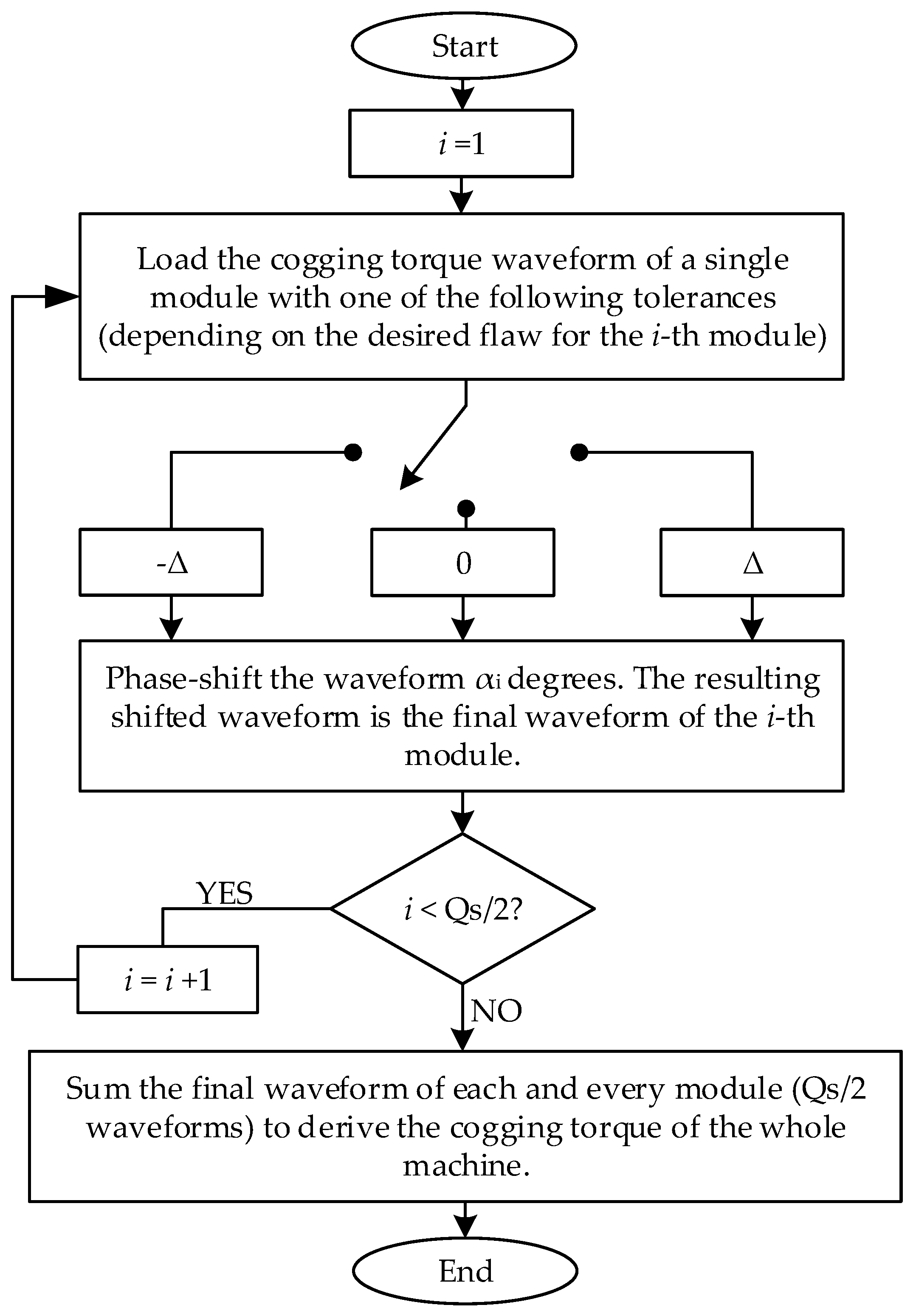
The overall cogging torque can be obtained by summing up the shifted waveforms of each module.
Different tolerances can be included in this superposition method. For instance, if angular displacement needs to be evaluated, the offset angle for the cogging torque waveform of each module is required to be adjusted, following the pertinent displacement tolerance. The general algorithm of the superposition method is described in the flowchart shown in Figure 12, which allows semi-analytical estimation of the cogging torque waveform for faultless and faulty machines.
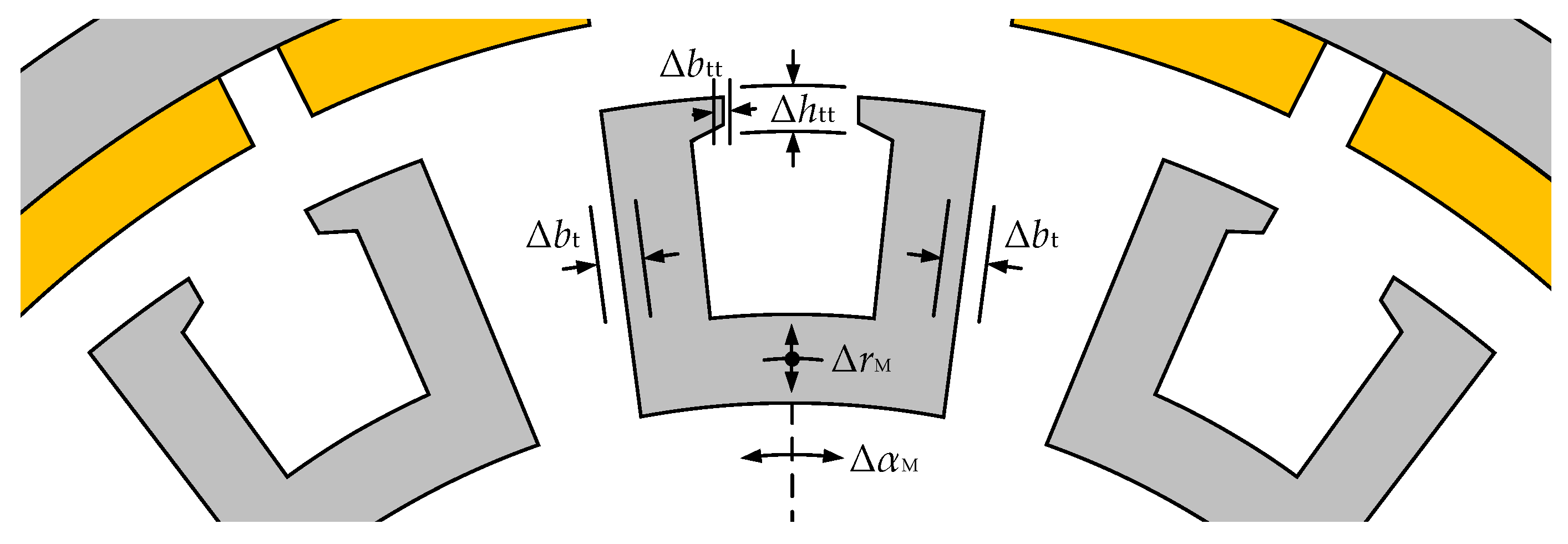
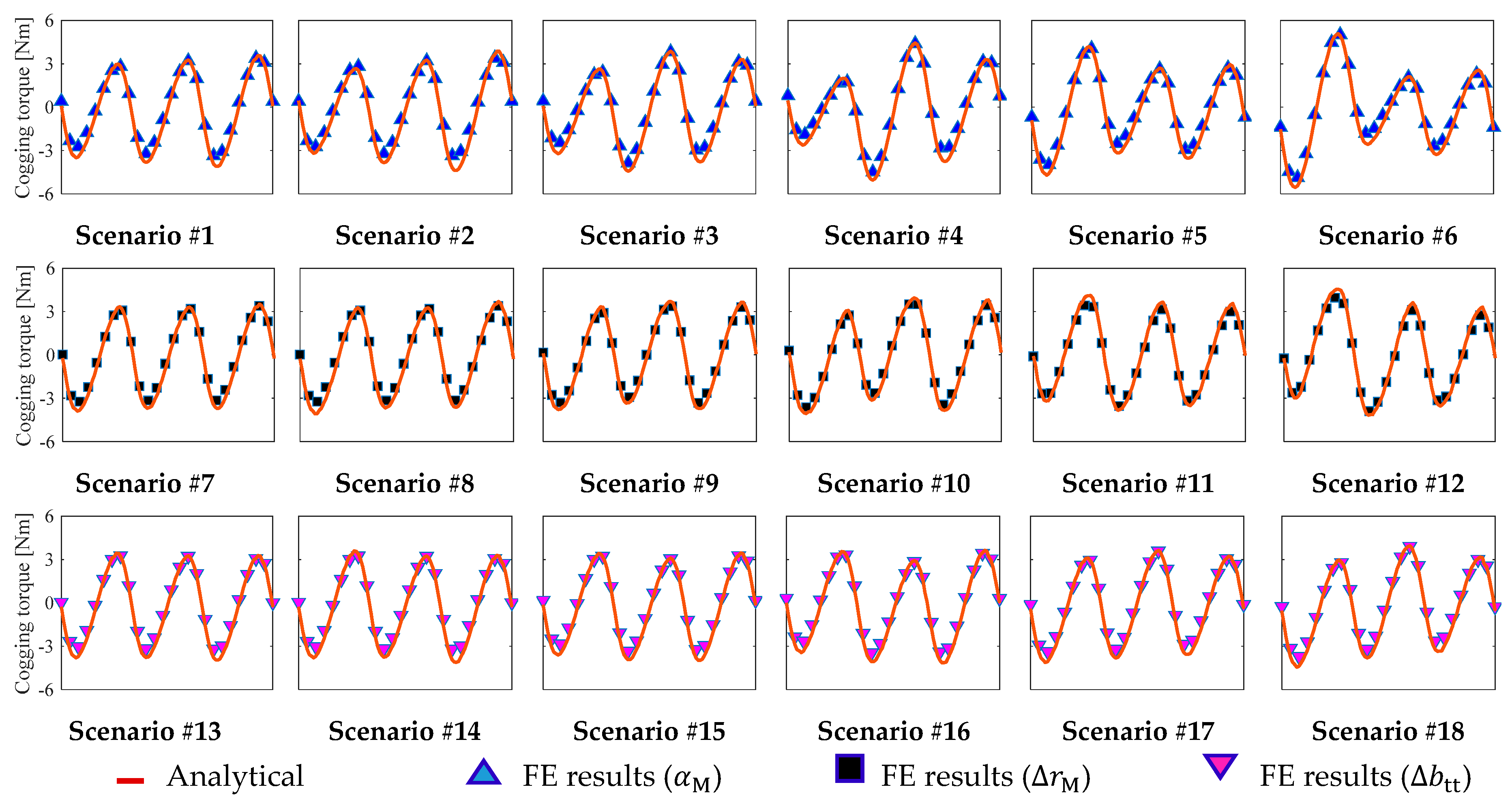
In order to validate the proposed superposition method, eighteen faulty scenarios are defined. These scenarios allow evaluating the cogging torque when angular displacements, radial displacements, and tooth–tip width deviations are applied to the modules separately. For example, the first six scenarios evaluate the angular displacement of the modules, while neglecting the other tolerances (radial displacement and tooth–tip width deviation), and the same principle is applied for every six scenarios. Also, the scenarios evaluate the presence of faults in one, three and seven modules of the machine following the same fault pattern.
Table 2 groups the main data of the validation scenarios, including the tolerance put through validation, the degree of tolerance and the modules affected by faults. The comparison of the cogging torque between FEA and the superposition method, for a 24-slot 28-pole machine is presented in Figure 13, considering the aforementioned scenarios.
It can be observed that in all 18 cases, the results provided by the different methods show good correspondence, even though the changes are large from scenario to scenario, hence proving the accuracy of the proposed method.

4.2. Results and Robustness Analysis

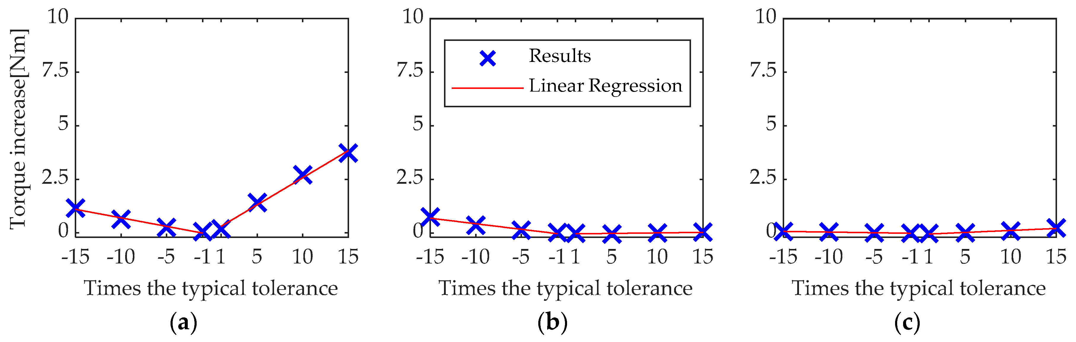
Aiming to evaluate the robustness of the selected topology, a full-range tolerance analysis considering two failures for each tolerance ( n = 2 ) is carried out by means of the superposition method presented in the previous subsection. The cases of study cover four different tooth–tip faultless/nominal widths (from 0 to 6 mm) and two magnet-to-pole arc faultless/nominal values from 0.8 to 0.9, summing up eight designs to be analyzed, as shown in Table 3.
In Section 3, angular and radial displacements of the modules, as well as the tooth–tip width tolerance, developed the most significant impacts on the cogging torque. Therefore, upon each of the eight designs, tolerance degrees of 0.05° and 0.10° will be considered for the angular displacement, and tolerance degrees of 0.1 and 0.2 mm will be applied both to the radial position and tooth–tip width of the modules.
A tolerance degree of Δ means that each module can have positive deviation (Δ), null deviation (0) or negative deviation (−Δ). E.g., a tooth–tip width subjected to a degree of tolerance of 0.1 mm means each one of the 12 modules of the machine (for a 24-slot 28-pole machine) can have tooth tips of width b tt + 0.1   mm , b tt or b tt 0.1   mm , where b tt is the faultless tooth–tip width.
To improve the visualization of the large amount of data obtained from this methodology, a statistical overview of the results is presented. A probability density distribution of the normalized peak-to-peak value of the cogging torque ( T ˜ cpp ) of each design, when all tolerance combinations are considered, is derived. T ˜ cpp is given by
T ˜ cpp = T cpp T m ,
where T m is the mean value of the full-load electromagnetic torques of the design, which depends, among other parameters, on the tooth–tip width and the magnet pole-arc ratio [10]. T m , for a TCW-MPMSM, can be approximated by using the no-load flux density distribution in the airgap of the machine and the linear current density [27], as:
T m = D 2 0 2 π B go ( θ ) A s ( θ ) D L ef 2 d θ ,
where D is the stator outer diameter; B go ( θ ) is the no-load flux density distribution in the airgap [10], A s ( θ ) is the linear current density along the perimeter of the stator, which depends on the number of turns, the winding factor and other parameters; and L ef is the effective core length.
Table 3 summarizes the mean value of the electromagnetic torque obtained with (6) for the eight designs analyzed.
After obtaining the probability density distribution of a design, two T ˜ cpp values are highlighted: the faultless/ideal case, and the expected value (probabilistic median of all tolerance cases).
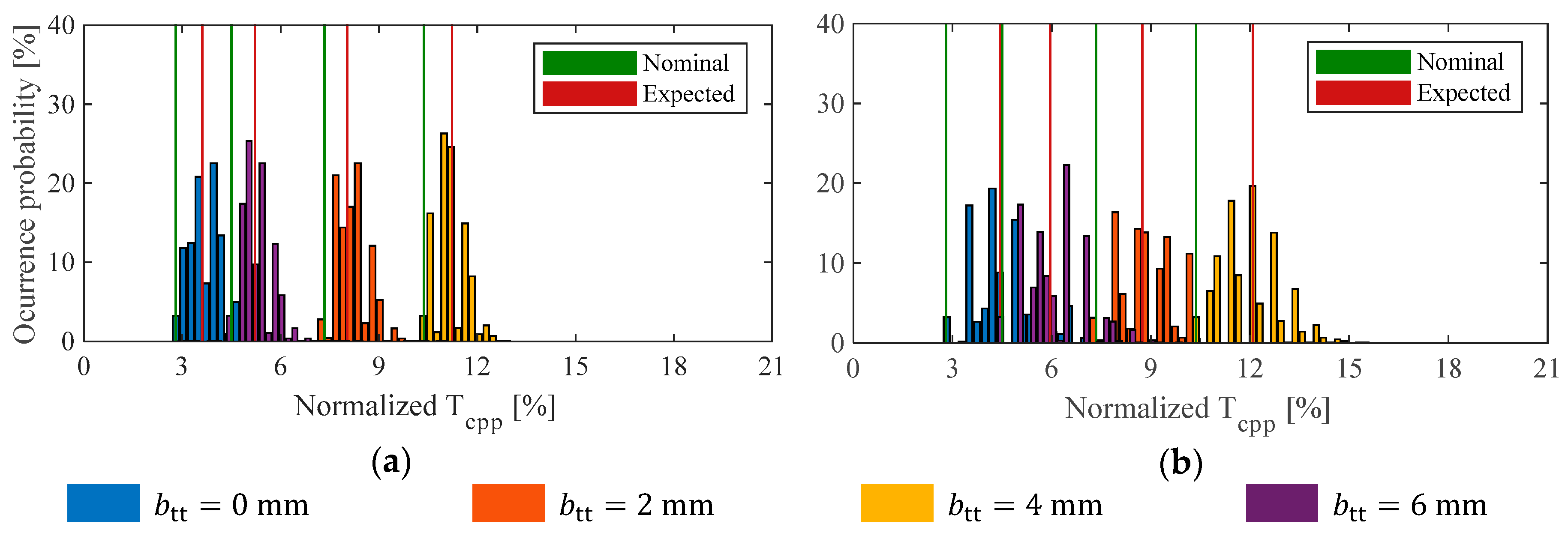
In Figure 14, the probability distribution of T ˜ cpp of the four designs with α PM = 0.8 (Design #1 to #4) are shown. Figure 14a shows the distribution when a tolerance degree of 0.05° is considered for the angular displacement of modules, whilst Figure 14b shows the distribution when the tolerance degree is 0.10°. Overall computation time for obtaining the results shown in Figure 14 was approximately 3 h, considering five FE simulations of one-magnet machine, following the procedure explained in the previous subsection, and carrying out the post-processing by means of the proposed superposition method. As roughly 1 million combinations were evaluated, carrying out this analysis entirely through FEA would be impractical to perform, as each simulation lasts 30 min until completion on a 6-core 12-thread processor.
From Figure 14, it can be noted that the T ˜ cpp density distributions (shown as groups of colored bars) substantially change for different values of tooth–tip width b tt 
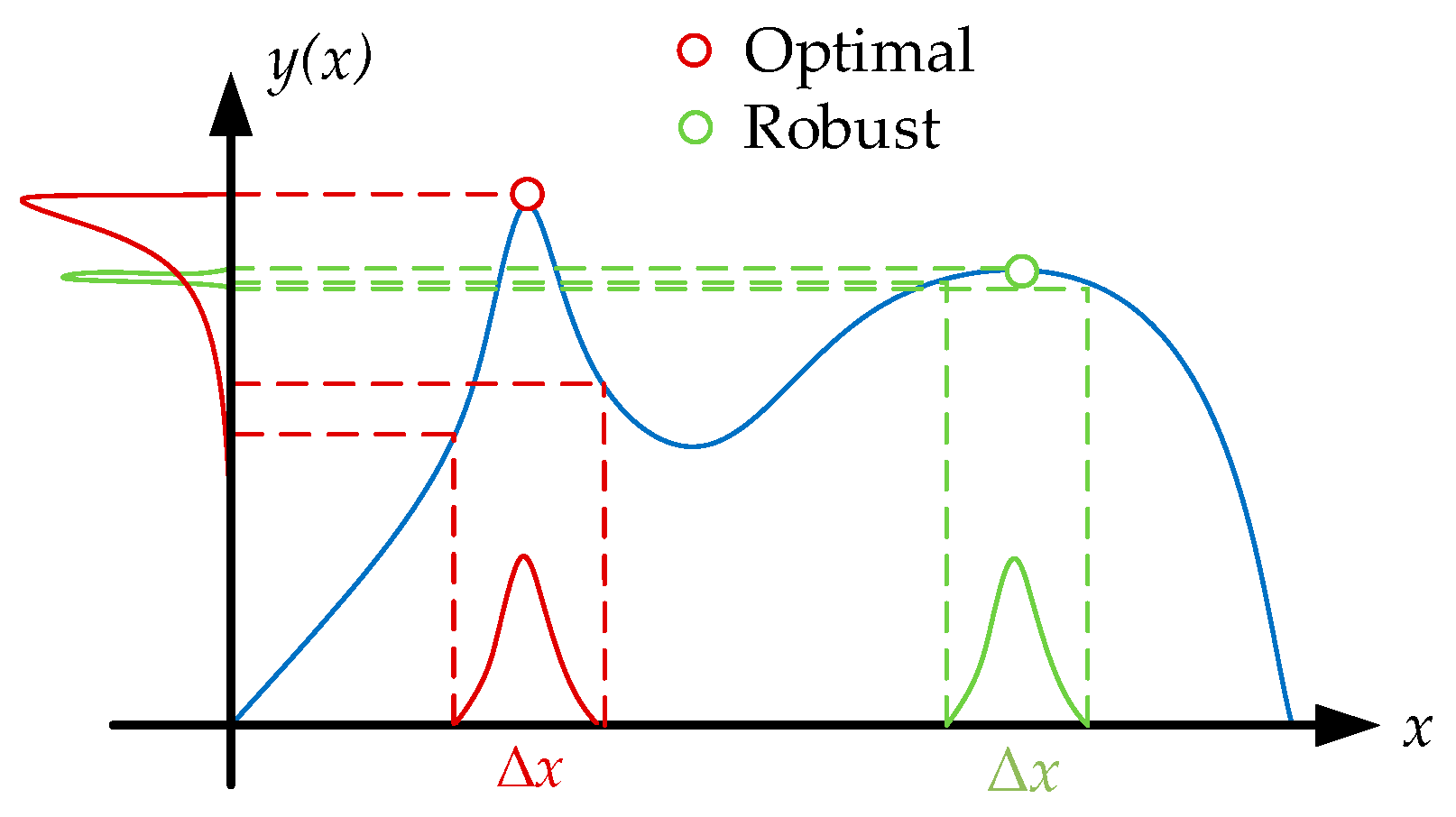
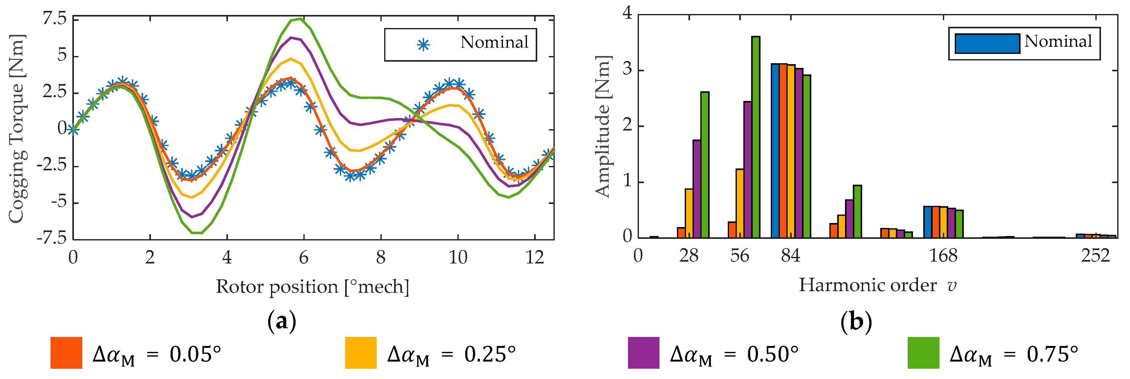
. More importantly, angular displacement of the modules causes T ˜ cpp to be higher than the nominal value, in agreement with the behavior shown in Figure 5.
The expected T ˜ cpp value, which is the probabilistic median of the results obtained for all possible faulty combinations, is also higher than the nominal one for the four designs. When the tolerance degree doubles, as depicted in Figure 14b when compared with Figure 14a, similar conclusions can be drawn: the expected cogging torque is higher than the nominal/faultless for all cases with α PM = 0.8 . As the tolerance degree increases (from 0.05° to 0.10°), the difference between the expected and the nominal values also increases.
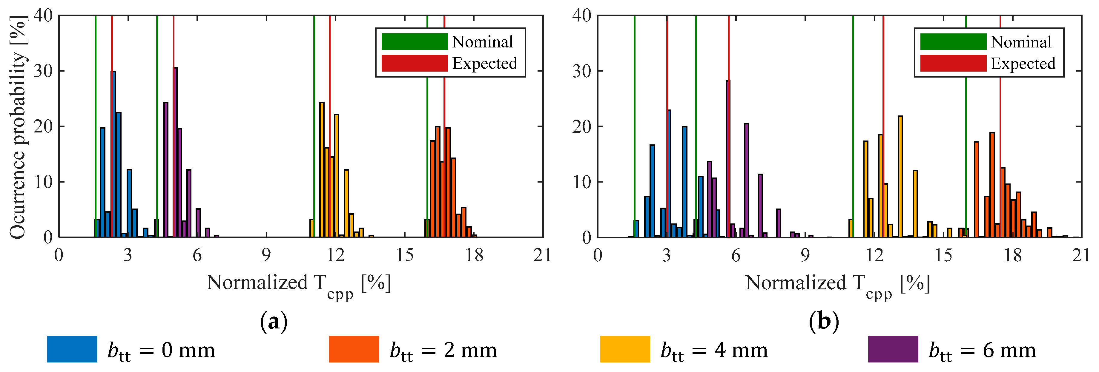
On the other hand, Figure 15 shows the probability distribution of T ˜ cpp of the four designs with α PM = 0.9 (Designs #5 to #8), evaluating two degrees of tolerances: 0.05° for the angular displacement of the modules in Figure 15a, and 0.10° in Figure 15b. From both figures it can be noted that, unlike the previous designs with α PM = 0.8 , adopting 2 mm wide tooth–tips develops the worst nominal cogging torque among all designs with α PM = 0.9 . Notice that the expected T ˜ cpp value (highlighted as a vertical red line) is higher than the nominal one (highlighted as a vertical green line) for the four designs, irrespective of the selected degree of tolerance.
With the aim of quantifying this behavior and describing the robustness of the eight designs, a robustness error ( e r r r ) is defined as
e r r r = T ˜ cpp expected T ˜ cpp nominal T ˜ cpp nominal = Δ T ˜ cpp T ˜ cpp nominal .
Table 4 summarizes the main results of the evaluation of the eight designs, when a tolerance degree of 0.05° is applied to the module angular position. These results take into account the nominal and expected values of T ˜ cpp , the difference between nominal and expected ( Δ T ˜ cpp ), and the robustness error ( e r r r ). Table 5 groups the results when a tolerance degree of 0.10° is evaluated.
From both tables, it can be noted that Δ T ˜ cpp is always positive, and its value is similar for the eight designs when a certain degree of tolerance is considered. This means that Δ T ˜ cpp can be considered as independent of the tooth–tip width as well as being independent of changes to the arc-to-pole ratio changes (e.g., in Table 4 Δ T ˜ cpp 0.7 % for all eight cases).
When the degree of tolerance doubles (from Table 4 to Table 5), Δ T ˜ cpp approximately doubles. This can be seen from Design #1 (Δ α PM = 0.8 and b tt = 0 mm) results: Δ T ˜ cpp is 0.8% in Table 4 (a tolerance degree of 0.05°), whereas Δ T ˜ cpp is 1.6% in Table 5 (a tolerance degree of 0.10°). Therefore, it can be stated that Δ T ˜ cpp mainly depends on the considered tolerance degree, while the nominal tooth–tip width and the pole-to-arc ratio show negligible influence. Furthermore, even when there are large differences between the nominal cogging torque of the designs, i.e., when different tooth–tips and pole-to-arc ratios are adopted, the variation of the cogging Δ T ˜ cpp due to mechanical tolerances is relatively constant for all the designs, when the same tolerance degree is considered.
On the other hand, in Table 6, the main results of the evaluation of the eight designs, for a tolerance degree of 0.1 mm over the radial displacement, are summarized, while Table 7 groups those results for a tolerance degree of 0.2 mm over the radial displacement.
Table 8, in turn, groups relevant results of the evaluation of the eight designs, when a tolerance degree of 0.1 mm over the tooth–tip width is considered, are summarized. Table 9 presents the results when a tolerance degree of 0.2 mm is evaluated.
Similar conclusions can be obtained from these four tables (Table 6, Table 7, Table 8 and Table 9) when compared to Table 4 and Table 5: the impact of radial displacement and tooth–tip width tolerances on the cogging torque of the machine is approximately independent of the nominal tooth–tip width and pole-to-arc ratio, and the difference between the expected and the nominal Δ T ˜ cpp mainly depends on the degree of tolerance evaluated.
However, it can be noted that tooth–tip width tolerances are not as relevant as angular displacement or radial displacement of the stator segments on modular machines. This can be seen, for example, by analyzing Design #8: angular displacement tolerances cause a robustness error of 16% and radial tolerances cause an error of 14%, whereas tooth–tip width tolerances generate a 5% error.
These findings further determine the value of the robustness error of each design: In (7), the numerator ( Δ T ˜ cpp ) of the expression has been found to be relatively constant for a certain tolerance degree. Then, e r r r can be taken as inversely proportional to the nominal cogging torque peak-to-peak value. This can be explained by separating the cogging torque “sources”. One “source” is the geometry of the design and the slot–pole count: the faultless machine generating the rated cogging torque, and the asymmetries/tolerances are another “source”, generating Δ T ˜ cpp . Therefore, minimizing the first source, i.e., the nominal cogging torque, will then lead to a higher relative cogging increment due to tolerances and a higher robustness error.
From the analysis, it can be concluded that, for lower cogging torque requirements, it will be necessary to have tighter tolerances, as lower nominal cogging torque designs exhibit lower robustness. This can be seen by analyzing the results of Design #5, which has the lowest nominal cogging–torque peak-to-peak value among the eight selected designs. However, e r r r for this design is 88% (the highest among all the designs), which means that the expected T ˜ cpp , once typical mechanical tolerances are considered, will be 88% higher (almost twice) than the original value. The optimization process of a machine, in its dimensioning stage, must be carried out carefully to integrate these properties if the goal is low cogging torque.

5. Conclusions

In this paper, the impact of dimensional and positioning tolerances on the cogging torque of a 24-slot 28-pole TCW-PMSM with a modular stator core has been analyzed. The parameters subjected to tolerance analysis were the angular and radial displacement of the stator modules, tooth–tip width, tooth–tip height, and tooth width. Using 2-D FE simulations over a single module of the machine, typical tolerance values were analyzed considering dimensional limits from 0.1 mm (tight tolerance) to 1.5 mm (loose tolerance). For all cases, the peak-to-peak value of the cogging torque linearly increases with the increment of the tolerance value. Furthermore, it was found that angular and radial displacement of the stator modules, and tooth–tip width (key parameters) have the most relevant impact on the peak-to-peak value of the cogging torque, whereas tooth width and tooth–tip height do not have a significant effect.
A superposition method was proposed to perform a full-range tolerance analysis considering all possible combinations of the three key parameters of the 24-slot 28-pole TCW-MPMSM. The proposed method was validated through several FE simulations of tolerance scenarios, showing good accuracy and significantly lower computation burden compared with a full-range FE-based analysis. From the results, it can be concluded that the increase in the cogging torque peak-to-peak value (having a faultless machine as the reference) is independent of the faultless tooth–tip width and the pole-to-arc ratio and only depends on the tolerance degree, defined as the absolute value of the possible deviations applied to the modules of the machine, as described in Section 4.1. In consequence, the robustness of the TCW-MPMSM, regarding cogging torque generation, is mostly dependent on the maximum degree of tolerance the manufacturing process handles, and it further is proportional to the peak-to-peak value of the cogging torque of the faultless design. In applications where TCW-MPSMs with reduced torque ripple are required, tight tolerances must be adopted for the design to be robust in the face of manufacturing imperfections.
The next step, which is out of the scope of this paper, is to scale the applicability of the superposition method, in order to consider combinations of different types of tolerances, hence providing a general overview of the impact of all relevant tolerances over the performance of TCW-MPMSMs.

Author Contributions

Conceptualization, C.M. and W.J.; methodology, C.M., W.J., G.B. and D.R.; software, D.R. and C.M.; validation, C.M. and D.R.; formal analysis, C.M. and W.J.; investigation, C.M.; resources, W.J., J.R., J.A.T. and G.B.; data curation, C.M.; writing—original draft preparation, C.M., W.J., G.B. and J.R.; writing—review and editing, C.M., W.J., G.B. and J.A.T.; visualization, C.M.; supervision, W.J., J.A.T. and G.B.; project administration, W.J.; funding acquisition, W.J. and J.R. All authors have read and agreed to the published version of the manuscript.

Funding

This work is supported by the COMET-K2 “Center for Symbiotic Mechatronics” of the Linz Center of Mechatronics, funded by the Austrian federal government and the federal state of Upper Austria, and by the ANID/CONICYT FONDECYT Iniciación 11170793.

Conflicts of Interest

The authors declare no conflict of interest.

References

  1. Dajaku, G.; Gerling, D. Low costs and high-efficiency electric machines. In Proceedings of the 2012 2nd International Electric Drives Production Conference (EDPC), Nuremberg, Germany, 15–18 October 2012; pp. 1–7. [Google Scholar]
  2. Jara, W.; Petrov, I.; Tapia, J.; Lindh, P.; Pyrhönen, J. Analytical model of tooth-coil winding permanent magnet synchronous machines with modular U-Shape stator. In Proceedings of the 2016 XXII International Conference on Electrical Machines (ICEM), Lausanne, Switzerland, 4–7 September 2016; pp. 145–151. [Google Scholar]
  3. Sui, Y.; Yin, Z.; Cheng, L.; Zheng, P.; Tang, D.; Chen, C.; Wang, C. Multiphase modular fault-tolerant permanent-magnet machine with hybrid single/double-layer fractional-slot concentrated winding. IEEE Trans. Magn. 2019, 55, 1–6. [Google Scholar] [CrossRef]
  4. Petrov, I.; Di, C.; Lindh, P.; Niemelä, M.; Repo, A.; Pyrhönen, J. Fault-tolerant modular stator concentrated winding permanent magnet machine. IEEE Access 2020, 8, 7806–7816. [Google Scholar] [CrossRef]
  5. Zhao, B.; Zheng, Y.; Zhu, C.; Liu, X.; Li, B. A novel modular-stator outer-rotor flux-switching permanent-magnet motor. Energies 2017, 10, 937. [Google Scholar] [CrossRef]
  6. Zheng, M.; Zhu, Z.Q.; Cai, S.; Xue, S.S. A novel modular stator hybrid-excited doubly salient synchronous machine with stator slot permanent magnets. IEEE Trans. Magn. 2019, 55, 1–9. [Google Scholar] [CrossRef] [Green Version]
  7. Li, G.J.; Zhu, Z.Q.; Chu, W.Q.; Foster, M.P.; Stone, D.A. Influence of flux gaps on electromagnetic performance of novel modular PM machines. IEEE Trans. Energy Convers. 2014, 29, 716–726. [Google Scholar] [CrossRef]
  8. Zhu, Z.Q.; Li, Y.X. Modularity techniques in high performance permanent magnet machines and applications. CES Trans. Electr. Mach. Syst. 2018, 2, 93–103. [Google Scholar] [CrossRef]
  9. Xu, L.; Xu, Y.; Gong, J. Analysis and optimization of cogging torque in yokeless and segmented armature axial-flux permanent-magnet machine with soft magnetic composite core. IEEE Trans. Magn. 2018, 54, 1–5. [Google Scholar]
  10. Madariaga, C.; Jara, W.; Tapia, J.; Riedemann, J.; Bramerdorfer, G.; Castro, P.; Sarlioglu, B. Analytical model and sensitivity analysis of tooth-coil-winding permanent magnet synchronous machine with modular U-shape stator. In Proceedings of the 2019 IEEE Energy Conversion Congress and Exposition (ECCE), Baltimore, MD, USA, 29 September–3 October 2019; pp. 1761–1768. [Google Scholar]
  11. Dajaku, G.; Xie, W.; Gerling, D. Reduction of low space harmonics for the fractional slot concentrated windings using a novel stator design. IEEE Trans. Magn. 2014, 50, 1–12. [Google Scholar] [CrossRef]
  12. Li, G.; Zhu, Z.; Foster, M.P.; Stone, D.A.; Zhan, H. Modular permanent-magnet machines with alternate teeth having tooth tips. IEEE Trans. Ind. Electron. 2015, 62, 6120–6130. [Google Scholar] [CrossRef] [Green Version]
  13. Montoya, C.; Tapia, J.; Pesce, C.; Riedemann, J.; Bramerdorfer, G.; Jara, W. Electromagnetic analysis of a novel PMSM with modular stator for low power generation. In Proceedings of the 2018 IEEE International Conference on Automation/XXIII Congress of the Chilean Association of Automatic Control (ICA-ACCA), Concepción, Chile, 17–19 October 2018; pp. 1–7. [Google Scholar]
  14. Bramerdorfer, G. Tolerance analysis for electric machine design optimization: Classification, modeling and evaluation, and example. IEEE Trans. Magn. 2019, 55, 1–9. [Google Scholar] [CrossRef]
  15. Heins, G.; Brown, T.; Thiele, M. Statistical analysis of the effect of magnet placement on cogging torque in fractional pitch permanent magnet motors. IEEE Trans. Magn. 2011, 47, 2142–2148. [Google Scholar] [CrossRef]
  16. Hyung, J.; Sarlioglu, B. Influences of manufacturing tolerance on performance of axial flux-switching permanent magnet machine. In Proceedings of the 2018 IEEE Energy Conversion Congress and Exposition (ECCE), Portland, OR, USA, 23–27 September 2018; pp. 7322–7329. [Google Scholar]
  17. Yang, L.; Zhao, J.; Liu, X.D.; Haddad, A.; Liang, J.; Hu, H. Effects of manufacturing imperfections on the circulating current in ironless brushless DC motors. IEEE Trans. Ind. Electron. 2019, 66, 338–348. [Google Scholar] [CrossRef]
  18. Coenen, I.; Giet, M.V.D.; Hameyer, K. Manufacturing tolerances: Estimation and prediction of cogging torque influenced by magnetization faults. IEEE Trans. Magn. 2012, 48, 1932–1936. [Google Scholar] [CrossRef]
  19. Bramerdorfer, G. A general investigation of the sensitiveness of brushless permanent magnet synchronous machines considering magnet tolerances. IEEE Trans. Magn. 2020, 56, 1–9. [Google Scholar] [CrossRef]
  20. Piña, A.; Xu, L. Analytical prediction of torque ripple in surface-mounted permanent magnet motors due to manufacturing variations. IEEE Trans. Energy Convers. 2016, 31, 1634–1644. [Google Scholar]
  21. Guo, B.; Huang, Y.; Peng, F.; Guo, Y.; Zhu, J. Analytical modeling of manufacturing imperfections in double-rotor axial flux PM machines: Effects on back EMF. IEEE Trans. Magn. 2017, 53, 1–5. [Google Scholar] [CrossRef] [Green Version]
  22. Lee, D.; Yoon, A.; Sirimanna, S.; Salon, S.; Haran, K. Impact of manufacturing tolerances on a low-reactance slotless PM synchronous machine. IEEE Trans. Energy Convers. 2020, 35, 366–374. [Google Scholar] [CrossRef]
  23. Klausnitzer, M.; Mockel, A. Quick cogging torque calculation for electronically commutated motors considering combinations of deviant and flawless magnets. In Proceedings of the International Symposium on Power Electronics Power Electronics, Electrical Drives, Automation and Motion, Sorrento, Italy, 20–22 June 2012; pp. 66–69. [Google Scholar]
  24. Taran, N.; Rallabandi, V.; Ionel, D.M.; Zhou, P.; Thiele, M.; Heins, G. A systematic study on the effects of dimensional and materials tolerances on permanent magnet synchronous machines based on the IEEE Std 1812. IEEE Trans. Ind. Appl. 2019, 55, 1360–1371. [Google Scholar] [CrossRef]
  25. Gasparin, L.; Cernigoj, A.; Markic, S.; Fiser, R. Additional cogging torque components in permanent-magnet motors due to manufacturing imperfections. IEEE Trans. Magn. 2009, 45, 1210–1213. [Google Scholar] [CrossRef]
  26. Zhu, Z.Q.; Ruangsinchaiwanich, S.; Chen, Y.; Howe, D. Evaluation of superposition technique for calculating cogging torque in permanent-magnet brushless machines. IEEE Trans. Magn. 2006, 42, 1597–1603. [Google Scholar] [CrossRef]
  27. Mahmoud, H.; Bianchi, N.; Bacco, G.; Chiodetto, N. Nonlinear analytical computation of the magnetic field in reluctance synchronous machines. IEEE Trans. Ind. Appl. 2017, 53, 5373–5382. [Google Scholar] [CrossRef]
Figure 1. The schematic of a permanent magnet synchronous machine (PMSM) with a modular stator and a surface-mounted permanent magnet (PM) external rotor.
Electronics 09 01594 g001
Figure 2. A trivial example for illustrating an optimal versus a robust solution based on a single parameter decision.
Electronics 09 01594 g002
Figure 3. The schematic of a section of the machine; tooth tips point towards the slot as Qs < p.
Electronics 09 01594 g003
Figure 4. Selected constructive parameters subjected to tolerance analysis.
Electronics 09 01594 g004
Figure 5. A comparison of the cogging torque of a 24-slot 28-pole TCW-MPMSM with Δ α PM = 0.9 and btt = 6 mm, considering Δ α M = 0 (symmetrical), Δ α M = 0.05°, Δ α M = 0.25°, Δ α M = 0.50° and Δ α M = 0.75°: (a) the waveform and (b) the frequency spectrum.
Electronics 09 01594 g005
Figure 6. The variation of the cogging torque in cases with different Δ α M in a single module.
Electronics 09 01594 g006
Figure 7. A comparison of the cogging torque of a 24-slot 28-pole TCW-MPMSM with Δ α PM = 0.9 and btt = 6 mm, considering Δ r M = 0 (symmetrical), Δ r M = ±0.1 mm, Δ r M = ±0.5 mm, Δ r M = ±1.0 mm, and Δ r M = ±1.5 mm: (a) positive deviations and (b) negative deviations.
Electronics 09 01594 g007
Figure 8. The variation of cogging torque in cases with different Δ α M in a single module.
Electronics 09 01594 g008
Figure 9. The variation of cogging torque of cases with: (a) different values of Δ b tt over a single module, (b) different values of Δ h tt over a single module, and (c) different values of Δ b t over a single module.
Electronics 09 01594 g009
Figure 10. The no-load flux lines of a 24-slot 28-pole TCW-MPMSM. Practically no flux lines completely cross the gap between the modules.
Electronics 09 01594 g010
Figure 11. A single active module is considered to compute the individual cogging torque through finite element (FE) simulations.
Electronics 09 01594 g011
Figure 12. The flowchart of the proposed algorithm to derive the cogging torque in faulty machines. Results for positive ( Δ ), null (0) and negative (− Δ ) tolerance over one module are obtained by means of finite element analysis (FEA). The i-th module cogging waveform will be one of the three simulated ones, but shifted by α i degrees.
Electronics 09 01594 g012
Figure 13. A comparison of the overall cogging torque between FEA and the superposition method, considering the 18 scenarios described in Table 2.
Electronics 09 01594 g013
Figure 14. A comparison of the cogging torque probability distributions of a 24-slot 28-pole TCW-MPMSM for different tooth–tip widths, with α PM = 0.8, considering two degrees of tolerance: (a) Δ α M = 0.05° and (b) Δ α M = 0.10°.
Electronics 09 01594 g014
Figure 15. A comparison of the cogging torque probability distributions of a 24-slot 28-pole TCW-MPMSM for different tooth–tip widths, where α PM = 0.9, considering two degrees of tolerance: (a) Δ α M = 0.05° and (b) Δ α M = 0.10°.
Electronics 09 01594 g015
Table 1. Main data of the selected machine.
SymbolQuantityValueUnit
l ef Effective core length70mm
r se Stator outer radius133mm
δ g Air-gap length2mm
h s Slot height21mm
b s Slot width24.8mm
h ys Height of the stator yoke10.8mm
h yr Height of the rotor yoke12mm
h t t Height of the tooth–tip2mm
h pm PM height5mm
B r PM remanence1.1T
μ r Relative recoil permeability1.041-
N Turns per phase1088-
Table 2. Validation scenarios.
# of Module (See Figure 10) and Applied Tolerance
# of ScenarioTolerance123456789101112
1 | Δ α M | = 0.05°+00000000000
2 | Δ α M | = 0.10°+00000000000
3 | Δ α M | = 0.05°++000000000
4 | Δ α M | = 0.10°++000000000
5 | Δ α M | = 0.05°+0+00+0+0
6 | Δ α M | = 0.10°+0+00+0+0
7 | Δ r M | = 0.1 mm+00000000000
8 | Δ r M | = 0.2 mm+00000000000
9 | Δ r M | = 0.1 mm++000000000
10 | Δ r M | = 0.2 mm++000000000
11 | Δ r M | = 0.1 mm+0+00+0+0
12 | Δ r M | = 0.2 mm+0+00+0+0
13 | Δ b tt | = 0.1 mm+00000000000
14 | Δ b tt | = 0.2 mm+00000000000
15 | Δ b tt | = 0.1 mm++000000000
16 | Δ b tt | = 0.2 mm++000000000
17 | Δ b tt | = 0.1 mm+0+00+0+0
18 | Δ b tt | = 0.2 mm+0+00+0+0
Table 3. The mean value of the full-load electromagnetic torque, for all eight designs subjected to a full-range tolerance analysis.
b tt ( mm ) 0246
α PM ( )
0.8Design #1Design #2Design #3Design #4
141.1 Nm145.2 Nm152.1 Nm162.9 Nm
0.9Design #5Design #6Design #7Design #8
143.5 Nm147.4 Nm156.3 Nm167.1 Nm
Table 4. The nominal and expected T ˜ cpp for all designs, when Δ α M = 0.05°.
b tt ( mm ) 0246
α PM ( )
0.8Nominal2.8%7.3%10.4%4.5%
Expected3.6%8.0%11.2%5.2%
Δ T ˜ cpp 0.8%0.7%0.8%0.7%
e r r r 29%10%8%16%
0.9Nominal1.6%16.0%11.1%4.3%
Expected2.3%16.7%11.7%5.0%
Δ T ˜ cpp 0.7%0.7%0.6%0.7%
e r r r 44%5%6%16%
Table 5. The nominal and expected T ˜ cpp for all designs, when Δ α M = 0.10°.
b tt ( mm ) 0246
α PM ( )
0.8Nominal2.8%7.3%10.4%4.5%
Expected4.4%8.7%12.1%6.0%
Δ T ˜ cpp 1.6%1.4%1.7%1.5%
e r r r 57%19%16%33%
0.9Nominal1.6%16.0%11.1%4.3%
Expected3.0%17.5%12.4%5.7%
Δ T ˜ cpp 1.4%1.5%1.3%1.4%
e r r r 88%9%12%33%
Table 6. The cogging increase for all the designs, when Δ r M = 0.1 mm.
b tt ( mm ) 0246
α PM ( )
0.8 Δ T ˜ cpp 0.8%0.8%0.7%0.7%
e r r r 29%11%7%16%
0.9 Δ T ˜ cpp 0.7%0.6%0.7%0.6%
e r r r 44%4%6%14%
Table 7. The cogging increase for all the designs, when Δ r M = 0.2 mm.
b tt ( mm ) 0246
α PM ( )
0.8 Δ T ˜ cpp 1.7%1.6%1.5%1.5%
e r r r 61%22%14%33%
0.9 Δ T ˜ cpp 1.5%1.3%1.4%1.2%
e r r r 94%8%13%28%
Table 8. The cogging increase for all the designs, when Δ b tt = 0.1 mm.
b tt ( mm ) 246
α PM ( )
0.8 Δ T ˜ cpp 0.4%0.3%0.3%
e r r r 6%3%7%
0.9 Δ T ˜ cpp 0.3%0.3%0.2%
e r r r 2%3%5%
Table 9. The cogging increase for all the designs, when Δ b tt = 0.2 mm.
b tt ( mm ) 246
α PM ( )
0.8 Δ T ˜ cpp 0.7%0.6%0.6%
e r r r 10%6%13%
0.9 Δ T ˜ cpp 0.6%0.6%0.4%
e r r r 4%5%9%

