Article

Voltage Space Vector Equivalent Substitution Fault-Tolerance Control for Cascaded H-Bridge Multilevel Inverter with Current-Tracking

1
Faculty of Electrical and Control Engineering, Liaoning Technical University, Huludao 125105, China
2
College of Mechanical Engineering, Liaoning Technical University, Fuxin 123000, China
*
Authors to whom correspondence should be addressed.
Electronics 2020, 9(1), 93; https://doi.org/10.3390/electronics9010093
Submission received: 12 December 2019 / Revised: 27 December 2019 / Accepted: 28 December 2019 / Published: 2 January 2020
(This article belongs to the Special Issue Multilevel Converters)

Abstract

:
A novel fault-tolerant control method based on the equivalent substitution of voltage space vector for cascaded H-bridge multilevel inverter with current-tracking is proposed in this paper. With this method, the fault effects on the voltage vector of each sector of the cascaded inverter is analyzed first. Then, an algorithm to substitute the voltage vector in fault state is developed. In the fault state, if the voltage vector selected by the original algorithm cannot be used normally, the redundant voltage vector with the position coincidence is preferentially selected for equivalent substitution. If there is no redundant coincidence vector, select the other vector whose position and effect are closest to it. Compared with the commonly used N + 1 redundancy method, this method does not require the spare cascaded units and can be applied to any class cascaded H-bridge multilevel inverter with current-tracking to improve its reliability. Finally, the effectiveness of the proposed method is validated by simulation and experiment results.

1. Introduction

Multilevel inverters with current-tracking are widely used in high voltage and large capacity active power filtering and reactive power compensation [1]. However, there are many power electronic components in this topology and the probability of failure are much higher [2]. Once the fault occurs, both the fault location and fault type are diagnosed by fault diagnosis [3], including open-circuit fault [4] and short-circuit fault [5]. The fault-tolerant control is performed on this.
According to the topology, the researches on fault-tolerant control of multilevel inverter are mainly as follows: Fault-tolerance of neutral point clamped (NPC) inverter [6], fault-tolerance of cascaded inverter [7], fault-tolerance of flying capacitor inverter [8], fault-tolerance of hybrid NPC four-leg inverter [9], and fault-tolerance of T-type inverter [10], etc. For all of these, the fault-tolerant control of cascaded multilevel inverters can be divided into hardware method and software method.
The hardware method usually requires the spare cascaded units [11] or other auxiliary modules [12,13] in the topology. The fault-tolerant control of cascaded inverter based on N + 1 redundancy is widely used [11,12]. Besides the series of the original N units of the cascaded inverter, one or more spare units are added to each phase. The fault-tolerant control method is proposed based on a three-phase voltage-source inverter is added as an auxiliary module in the cascaded inverter in [13]. An additional module is added to the load-side of the cascaded inverter, which can flexibly carry out structure recombination according to different faults to achieve fault-tolerance in [14]. Because the inverter works in non-fault state, the hardware method wastes spare unit and makes the topology more complicated.
The software method realizes fault-tolerant control through the algorithm and does not need to change the topology of the cascaded inverter. It can save the cost of hardware and simplify the topology. The researches of software method mainly include the following three types:
(1)
Short-circuiting the faulty unit and working in the state of reduced-capacity: This method is suitable for single-phase cascaded inverter [15]. In addition to short-circuiting the faulty unit, the non-faulty units corresponding to the faulty unit in the other two phases are also normally shielded in the three-phase inverter [16]. However, some non-faulty units are not fully utilized and there is a waste of hardware resources. The seven-level cascaded inverter was taken as an example in [17] to prove that in this fault-tolerant control, the effective output voltage amplitude of the inverter fell from 5.19Vdc in non-fault state to 3.46 Vdc in fault state, where Vdc was the DC-link voltage of the cascaded unit.
(2)
Neutral Point Shift (NPS): This method can implement fault-tolerant control in the case of only bypassing fault units [18]. The NPS is mostly used for control algorithms with modulated waves, which is not suitable for the method in this paper. With the NPS approach, the low-order harmonic and other issues can be rising [19].
(3)
Adjusting the DC-link voltage of the inverter: The DC-link voltage of the non-faulty unit in the fault phase was raised to the original 2N/(2N − 1) times in [20,21] and the fault- tolerant control was performed on the basis of this. But the method is only suitable for the case where the DC-link voltage is controllable, and the voltage stress of the power electronic component can be increased. Therefore, a fault-tolerant control method combining NPS with the adjustment of DC-link voltage was proposed in [22,23], which can reduce the voltage stress of the power electronic component under the fault state. With this method, the increase of the DC-link voltage changes the position of the voltage vectors, which makes the selection algorithm of voltage vector complex.
There are many voltage vectors in cascaded inverter and their positions are often coincident or very close. In the fault state, if the voltage vector selected by the original algorithm cannot be used normally, it can be replaced by the redundant voltage vector of position coincidence or by other vectors whose position and effectiveness are close to it. To our best knowledge, there is no study using voltage vector equivalent substitution to achieve fault-tolerant control of cascaded multilevel inverter.
In summary, a fault-tolerant control method based on voltage vector equivalent substitution for cascaded H-bridge inverter with current-tracking is proposed. Compared with the hardware method, it does not require spare cascaded unit. Compared with the method in (3), it does not require to change the DC-link voltage of the inverter, either. It can make full use of the remaining non-faulty units to achieve fault-tolerant control in the case of only bypassing the faulty unit. However, the non-faulty units corresponding to the faulty unit in the other two phases are also shielded in the three-phase inverter in (1). This method is more suitable for cascaded inverter with current-tracking, which does not require the output three-phase voltage with symmetry strictly.

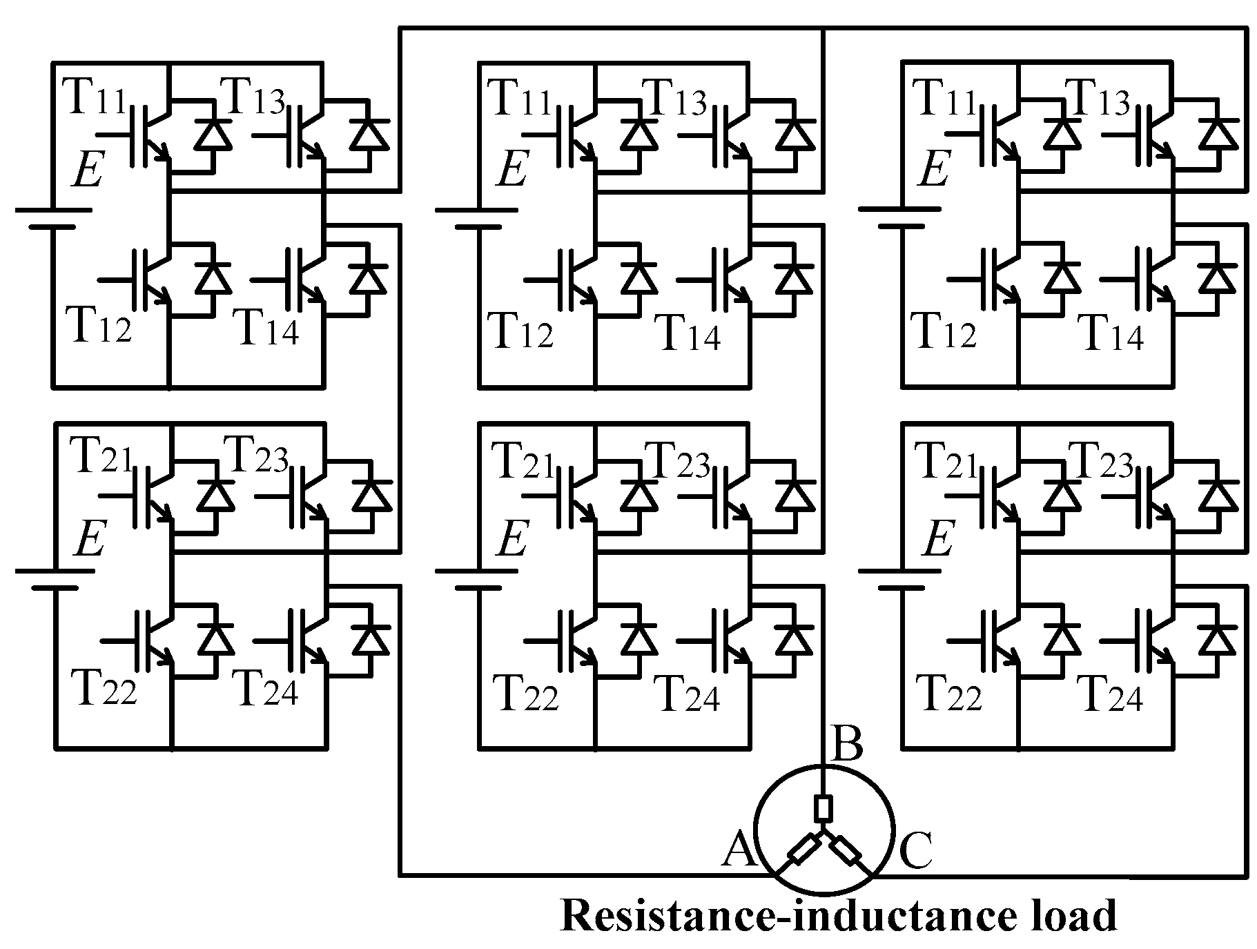
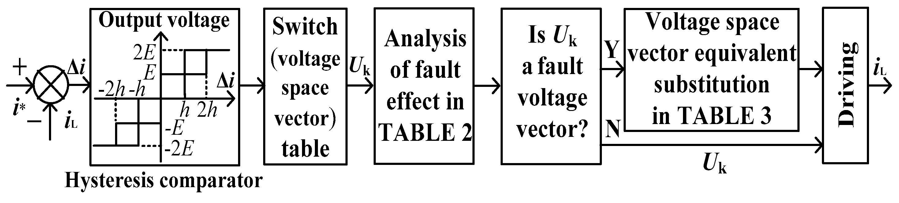
2. Strategy of Current-Tracking Control

Figure 1 shows the topology of 2-class cascaded H-bridge multilevel inverter, which is connected to RL load. The DC-link voltage of the cascaded unit is E. As shown in Figure 2, the error between the actual value of the output current of the inverter and the reference current is determined by the current hysteresis comparator. The switching states and voltage space vectors of inverter will be selected by the Equations (1)–(3) on the basis of current-tracking error. The “equivalent substitution” of the voltage vector is performed to realize fault-tolerant control in the fault state.
U a = { 2 E i a 2 h E h i a < 2 h 0 h < i a < h E 2 h < i a h 2 E i a 2 h
U b = { 2 E i b 2 h E h i b < 2 h 0 h < i b < h E 2 h < i b h 2 E i b 2 h
U c = { 2 E i c 2 h E h i c < 2 h 0 h < i c < h E 2 h < i c h 2 E i c 2 h
Let Ua, Ub, Uc be the output voltage values of phases A, B, and C. There are five levels and they are −2E, −E, 0, E, and 2E which correspond to the five states “0, 1, 2, 3, 4” respectively. For example, states “4,” “0,” and “0” in the voltage space vector “400” represent Ua = 2E, Ub = −2E, and Uc = −2E, where state “4” corresponds to the switching state of phase A as shown in line 2 of Table 1. The switching states of phase B and phase C can be obtained in the same way.
Taking ∆ia ≥ 2h of phase A as an example, it is shown that the current-tracking error of phase A is large and the load current is lower than the reference value and the voltage value 2E should be selected to eliminate the tracking error quickly. The output voltage values of phase B and phase C can be obtained in the same way according to the Equations (2) and (3).
There are many switching states for some voltage vectors and levels. Taking Ua = 0 V as an example, there are six switching states for it. In [24,25], the switching state selection method in this case is proposed based on the principle of minimal change of the switching state, which is not repeated here.

3. Fault-Tolerant Control Strategy in Fault State

The number of series units of each phase of cascaded H-bridge inverter is N. When an open-circuit or short-circuit fault occurs in the cascaded unit, the faulty unit is first quickly removed and fault-tolerant control is performed.

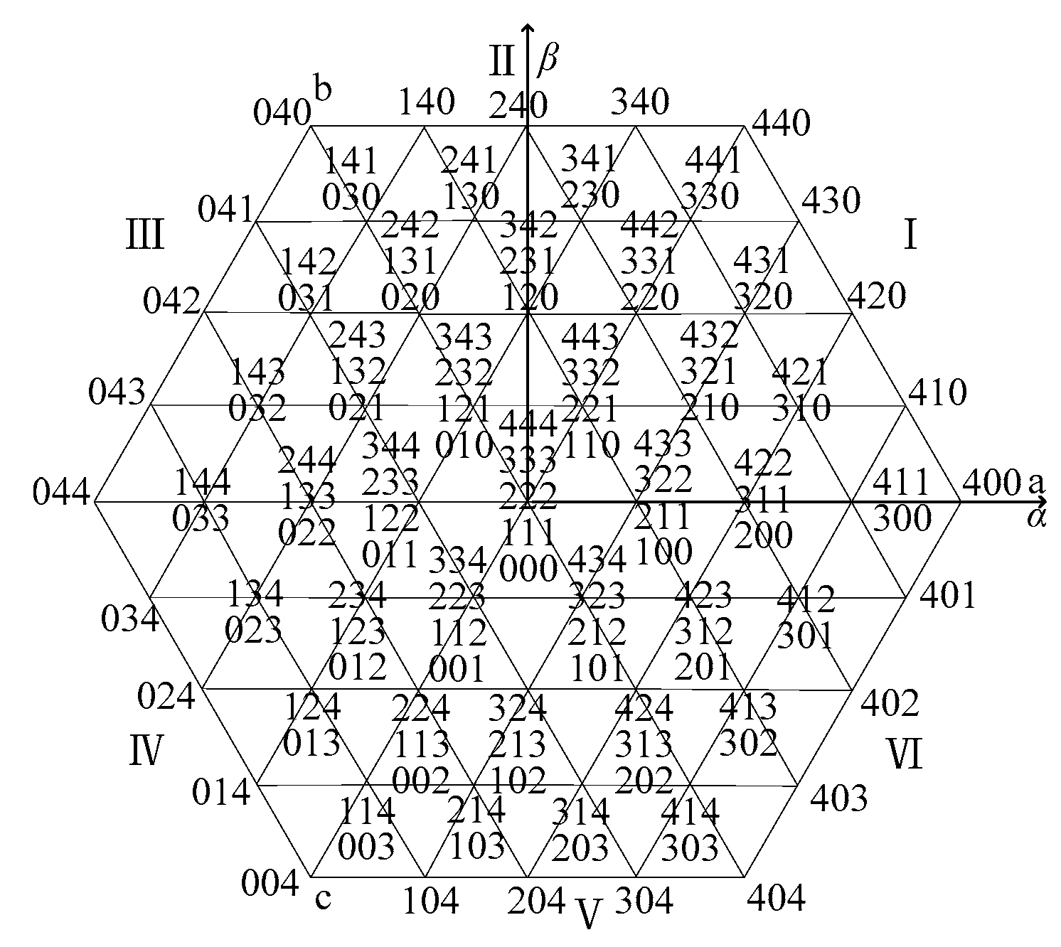
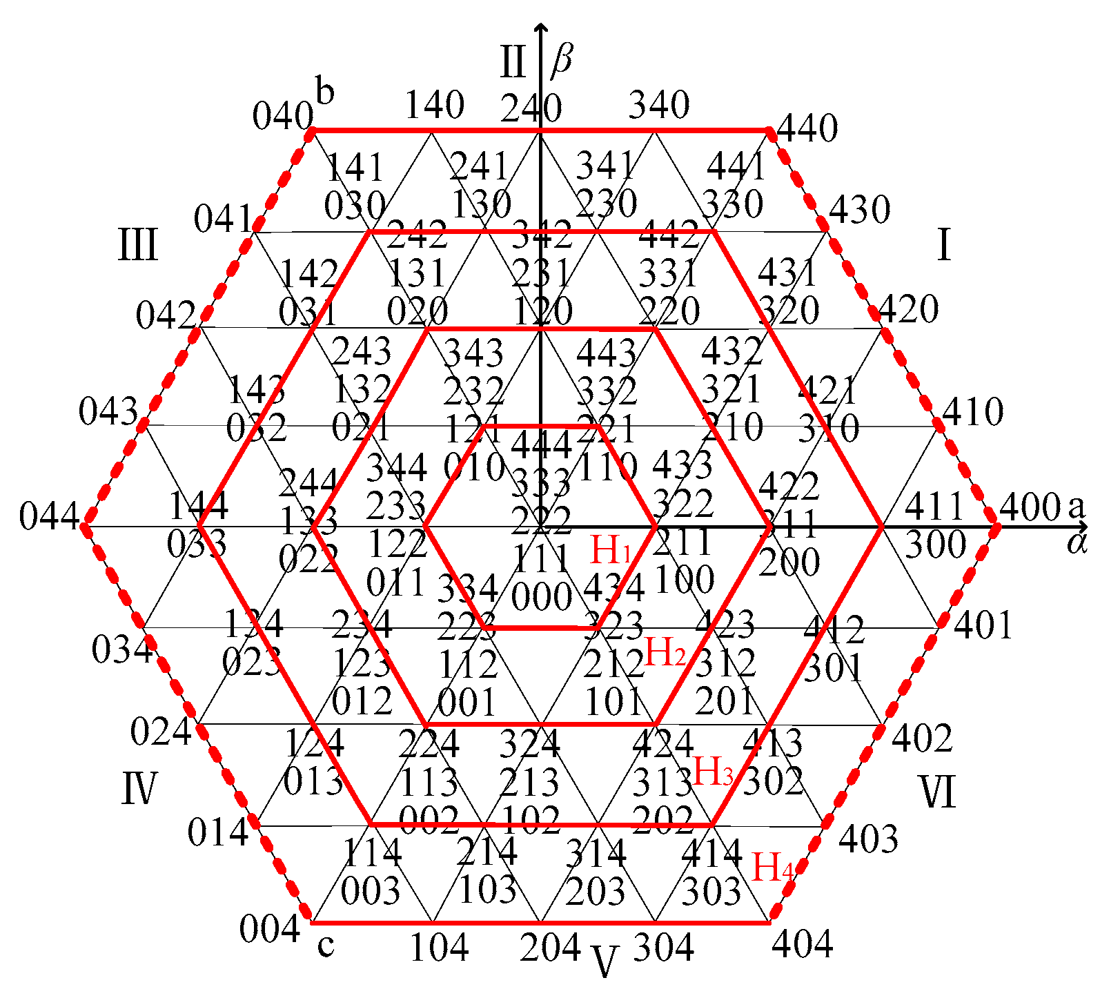
3.1. Analysis of Fault Effect

When m (0 < m < N) units in one phase of the N-class cascaded H-bridge inverter fail, the number of levels in this phase is reduced by 2 m and the effective voltage vectors of some sectors in the voltage vector diagram will be also reduced. When the fault occurs in phase A, B, and C respectively, the influence on the voltage vectors of each sector is shown in Table 2. In the table, “√” indicates that the fault has an effect on the sector and “×” indicates no effect, which does not include the voltage vectors at the sector boundary. The voltage vector that cannot be used normally in the event of a fault is called fault voltage vector. The voltage vector that can be used normally without being affected by the fault is called non-fault voltage vector.
Taking N = 2 as an example, a voltage vector diagram of non-fault is shown in Figure 3.
When one cascaded unit in phase A fails, there will be no levels of −2E and 2E in phase A, that is states “0” and “4”. The voltage vectors corresponding to the 2 states in phase A are fault vectors. The voltage vector diagram in the fault state is shown in Figure 4.
The fault voltage vector on the dotted line has no non-fault voltage vector that coincides with its position and the fault voltage vector on the solid line has the non-fault voltage vector that coincides with its position. Taking the voltage vector “400” as an example, because of the fault of one unit in phase A, the state “4” cannot occur. In other words, the vector “400” is the fault voltage vector and there is no other non-fault voltage vectors whose positions coincide with it, so that it is on the dotted line. Although the vector “411” is also a fault voltage vector, it can be replaced equivalently because its position coincides with the vector “300”. Thus, it is placed on the solid line. Similarly, the voltage vector diagrams can be obtained when one unit fails in phase B or C.
In Figure 2, if the voltage vector Uk = (x, y, z) selected by (1–3) is the fault voltage vector, the non-fault vector with the position coincidence is preferentially selected for equivalent substitution. If there is not, the other non-fault vector whose position and effect are the closest is selected for substitution. Where x, y, and z are integers greater than or equal to 0.

3.2. Strategy for Voltage Vector Substitution

The substitution method of the fault vector is as follows:
There are 2N regular hexagons (excluding the midpoint) from the midpoint in the voltage vector diagram of the N-class cascaded H-bridge inverter, which are named H1, H2 … H2N, respectively. Take the fault of m (0 < m < N) units in the phase A as an example.
(1) When the Uk = (x, y, z) is located around the outermost mth regular hexagon in the voltage vector diagram, there is no non-faulty voltage vector with position coincidence to be selected and the method of vector substitution is as follows:
When Uk is in sector I or VI, the voltage vector (x − 1, y, z) is first selected. If the voltage vector (x − 1, y, z) is also the fault voltage vector, the voltage vector (x − 2, y, z) is selected, etc. When Uk is in sector III or IV, the voltage vector (x + 1, y, z) is first selected. If the voltage vector (x + 1, y, z) is also the fault voltage vector, the voltage vector (x + 2, y, z) is selected, etc. It is not affected by the fault when Uk is in the sector II or V.
The larger the number of cascaded units N is, the smaller the errors of phase and amplitude are before and after vector substitution.
(2) When Uk = (x, y, z) is around hexagons j (1 ≤ j ≤ 2Nm), there is non-faulty voltage vector with position coincidence to be selected and the method of vector substitution is as follows:
When Uk is in sector I or VI, the voltage vector (x − 1, y − 1, z − 1) is first selected. If the voltage vector (x − 1, y − 1, z − 1) is also the fault voltage vector, the vector (x − 2, y − 2, z − 2) is selected, etc. When Uk is in sector III or IV, the voltage vector (x + 1, y + 1, z + 1) is first selected. If the vector (x + 1, y + 1, z + 1) is also the fault voltage vector, the voltage vector (x + 2, y + 2, z + 2) is selected, etc. It is not affected by the fault when the Uk is in the sector II or V. In the same way, the method of voltage vector substitution can be obtained when m units in phase B or C are in fault.
As shown in Figure 4, when one unit in phase A of 2-class cascaded inverter is in fault, the above method is shown in Table 3. There are four regular hexagons in the voltage vector diagram of the 2-class cascaded H-bridge inverter, which are named H1, H2, H3, H4, respectively. Taking the vector “400” as an example, it is located on the outermost hexagon H4 in Figure 4. There is no non-faulty voltage vector with position coincidence to be selected for “400.” The voltage vector “300” should be selected according to Table 3. The switching states of phase A before and after substitution can be seen from Table 1, where “on” represents turn-on, “off” represents turn-off and the switching state of the faulty unit is represented by “×”.
Similarly, the method of voltage vector substitution is available when one unit is in fault in phase B or C. The more the number of cascaded units is, the more voltage vectors with coincident positions are and the smaller the error of the voltage vector substitution is.

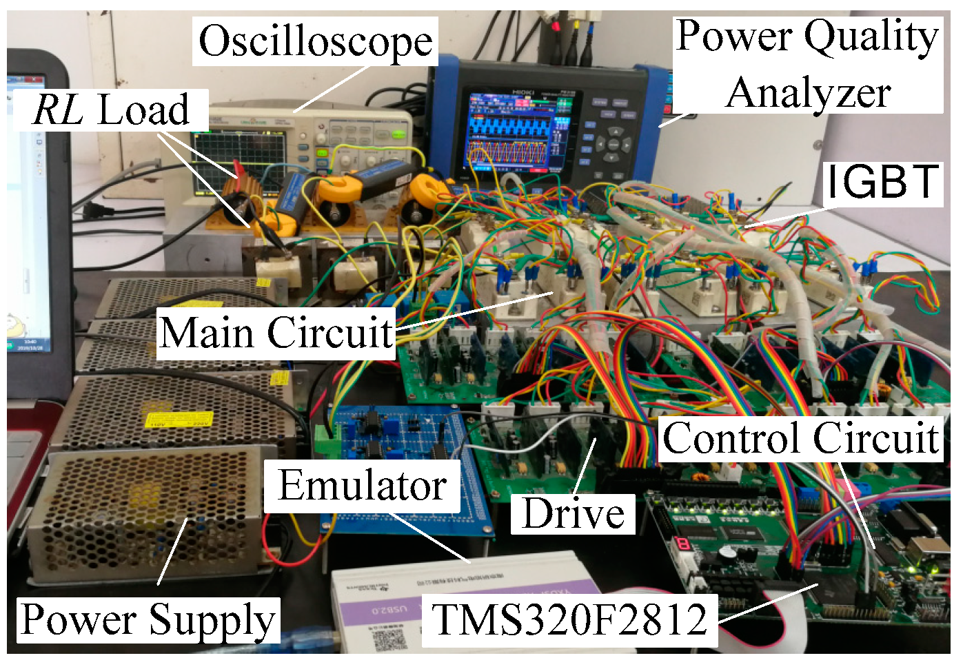
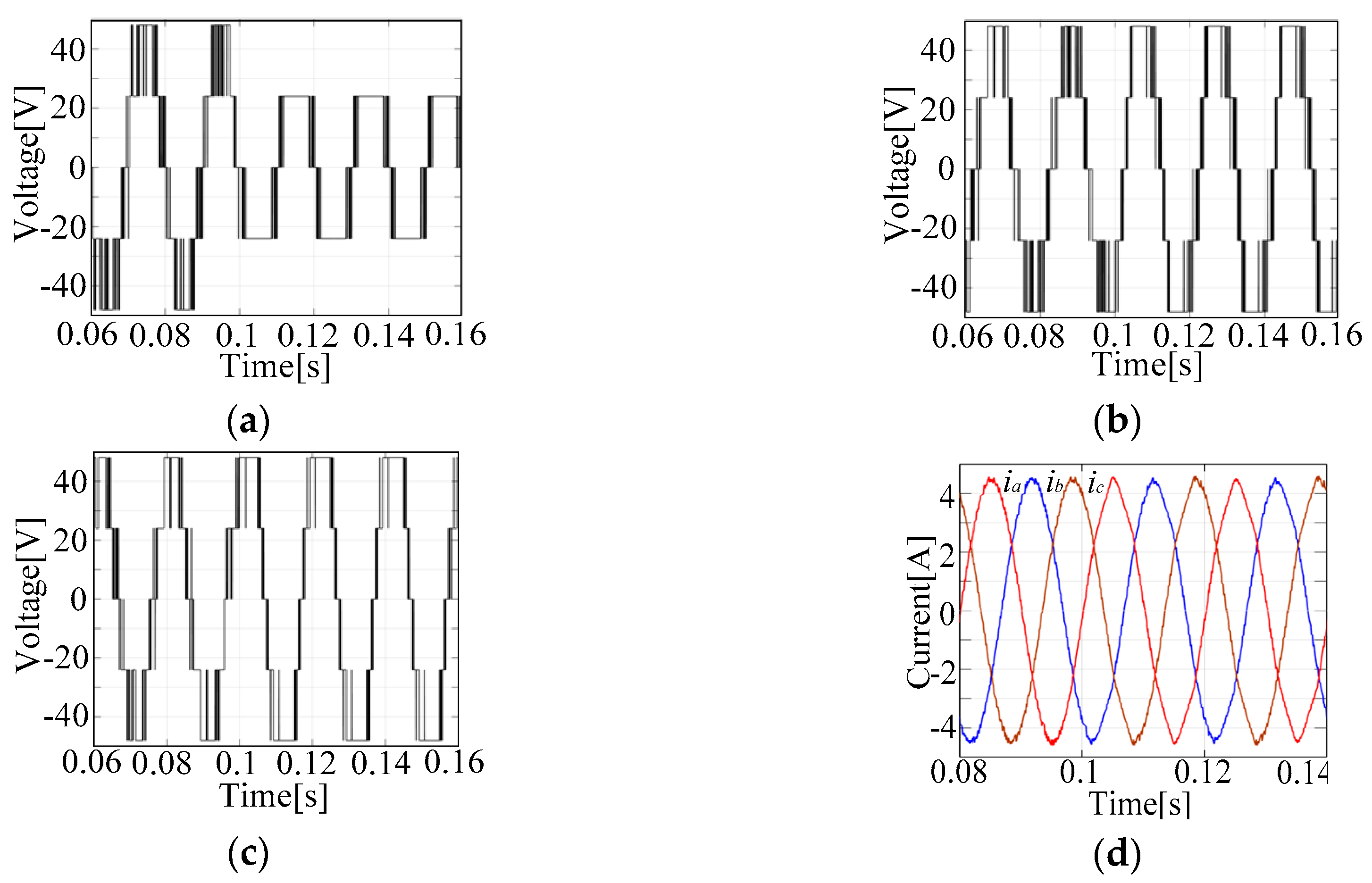
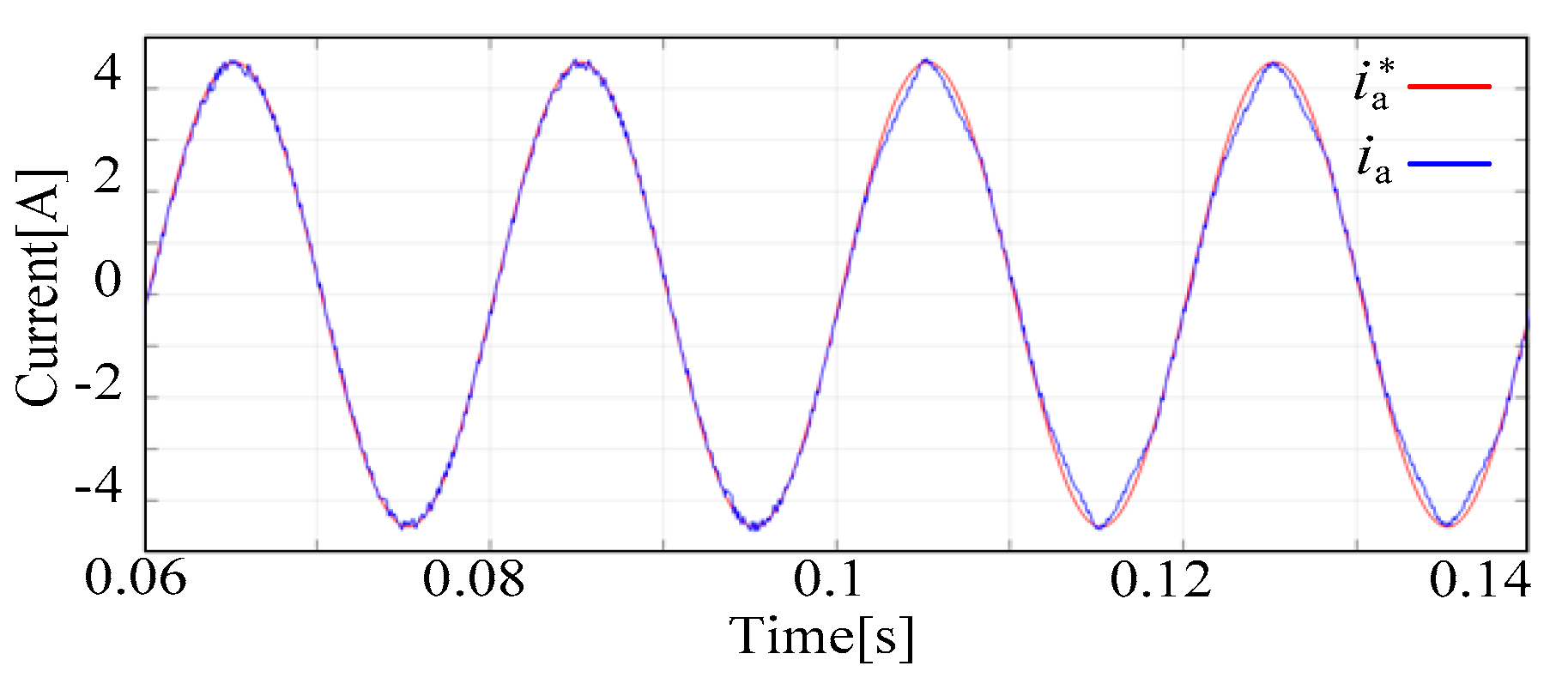
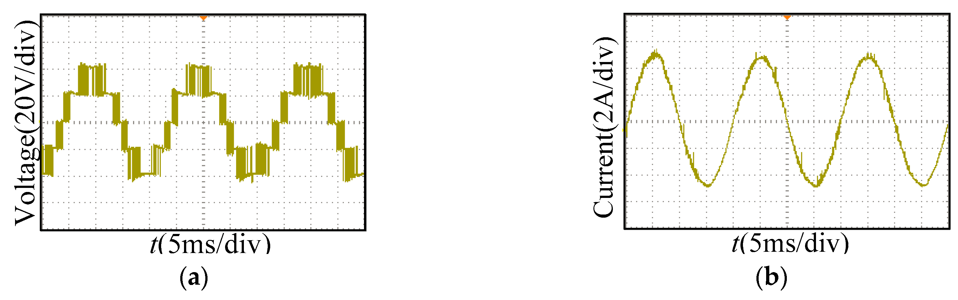
4. Simulation and Experiment

The experimental system of the 2-class cascaded H-bridge multilevel inverter is shown in Figure 5. The method is verified and analyzed by Simulink and experimental system. The power electronic component in the inverter is IGBT. The driving circuit adopts IGBT integrated driving module DA962D and the system main control chip adopts 32-bit DSP TMS320F2812. The tracking reference current of the inverter is sine wave. Its amplitude is 4.5 A and frequency is 50 Hz. The hysteresis width h is 0.2A. The DC-link voltage of the cascaded unit is 24 V. Inverter is connected to RL load with R = 10 Ω and L = 5 mH. In the experiment, the oscilloscope is DS1052E and power quality analyzer is HIOKI PW3198.
The simulation waveforms of the inverter are shown in Figure 6 when one unit of the phase A is in fault. The fault occurred in the simulation at 0.1 s. When the fault occurs, it can be seen from Figure 6a that only one unit in A-phase can work properly, which leads to the decrease of levels of ua. As can be seen from Figure 6b,c that the number of voltage levels of the B-phase and C-phase does not change. But the probability of the levels of 2E and −2E in the waveform is higher than that before the fault.
It can be seen from Figure 6d and Figure 7 that the actual value of the output current of the inverter can still track the reference current in fault state. It is proved that this method can realize fault-tolerance control.
In order to simulate the fault state in the experiment, the first unit of the phase A is shorted. Figure 8a,b are the experimental waveforms of the voltage and current of phase A before the fault. The waveforms of voltage and current of phase B and phase C before the fault are basically the same as the waveforms of phase A, but the phase are mutually different by 120°. It can be seen that the current waveform is closer to the sine wave and the reference current can be tracked accurately in non-fault state.
The voltage waveforms of phase A and phase B in the fault state are shown in Figure 9a,b. The waveform of voltage of phase C is basically the same as the waveform of phase B, but the phase are mutually different by 120°. It can be seen that the number of the levels of phase A in the fault state is reduced from 5 to 3 levels, which is consistent with the simulation analysis. The number of the levels of phase B remains unchanged and it is still 5 levels. However, compared with the non-fault state, the probability of the levels of 2E and −2E is larger. The reason is that the states “0” and “4” cannot appear in phase A because of the fault. The probability of the states “0” and “4” in phase B and phase C increases in the process of voltage vector equivalent substitution. For example, the voltage vector selected before the fault is “411” and the fault of phase A causes the vector to become the fault vector. At this time, the coincident vector “300” is selected by the fault-tolerant algorithm for equivalent substitution, which directly causes the output voltage of the phase B and phase C to change from the original −E to −2E. So the probability of the levels of 2E and −2E becomes larger in phase B and phase C.
Figure 10a,b shows the experimental waveforms of currents ia and iabc in the fault state. They are close to the sinusoidal current waveform with an amplitude of 4.5 A and a period of 50 Hz. It is proved that the actual current value can accurately track the reference value with this method and the fault-tolerant control is effective in fault state. The voltage and current waveforms in the experiment are basically consistent with the simulation results. However, because of the time delay caused by digital control, the distortion of the experimental waveforms is slightly larger than the simulated waveform.
It can be seen from Figure 11 that the total harmonic distortion rate of the current in phase A before the fault is 1.77% (Figure 11a) and which is 3.07% (Figure 11b) after the fault. The results of phase B and phase C are basically the same as phase A. It is proved that this method can realize fault tolerance control.

5. Conclusions

A fault-tolerant control method based on the equivalent substitution of voltage vector for cascaded H-bridge multilevel inverter with current-tracking was proposed. The effect of fault on the voltage vector of each sector of the cascaded inverter is analyzed and a method of voltage vector substitution in fault state is proposed to achieve fault-tolerant control. Simulation and experimental results show that by using the proposed method, the actual current value can track the reference value in fault state. The method does not require redundant cascaded units. It can reduce the size and simplify the main circuit and can be applied to any class cascaded H-bridge multilevel inverter with current-tracking. It can be tried to apply this method to active power filter and STATCOM in the next step to improve its reliability.

Author Contributions

G.L. and C.L. write the original manuscript and Y.W. proofreads the manuscript. All authors have read and agreed to the published version of the manuscript.

Funding

This research was funded by Natural Science Foundation of Liaoning Province, China, grant number 20180550268.

Acknowledgments

The authors thank Liaoning Technical University for providing the support to enable this research to be carried out.

Conflicts of Interest

The authors declare no conflict of interest.

References

  1. Sajadi, R.; Iman-Eini, H.; Bakhshizadeh, M.K.; Neyshabouri, Y.; Farhangi, S. Selective Harmonic Elimination Technique with Control of Capacitive DC-Link Voltages in an Asymmetric Cascaded H-Bridge Inverter for STATCOM Application. IEEE Trans. Ind. Electron. 2018, 65, 8788–8796. [Google Scholar] [CrossRef] [Green Version]
  2. Xu, S.; Zhang, J. Overview of fault-tolerant techniques for multilevel voltage source inverters. Trans. China Electrotech. Soc. 2015, 30, 39–50. [Google Scholar]
  3. Wu, Y.; Jiang, B.; Lu, N. A Descriptor System Approach for Estimation of Incipient Faults with Application to High-Speed Railway Traction Devices. IEEE Trans. Syst. Man Cybern. Syst. 2019, 49, 2108–2118. [Google Scholar] [CrossRef]
  4. Yang, S.; Tang, Y.; Wang, P. Seamless Fault-Tolerant Operation of a Modular Multilevel Converter with Switch Open-Circuit Fault Diagnosis in a Distributed Control Architecture. IEEE Trans. Power Electron. 2018, 33, 7058–7070. [Google Scholar] [CrossRef]
  5. de Oliveira, A.B.; Moreno, R.L.; Ribeiro, E.R. Short-Circuit Fault Diagnosis Based on Rough Sets Theory for a Single-Phase Inverter. IEEE Trans. Power Electron. 2019, 34, 4747–4764. [Google Scholar] [CrossRef]
  6. Selvaraj, R.; Desingu, K.; Chelliah, T.R.; Khare, D.; Bharatiraja, C. Fault Tolerant Operation of Parallel-Connected 3L-Neutral-Point Clamped Back-to-Back Converters Serving to Large Hydro-Generating Units. IEEE Trans. Ind. Appl. 2018, 54, 5429–5443. [Google Scholar] [CrossRef]
  7. Wu, P.; Cheng, P. A Fault-Tolerant Control Strategy for the Delta-Connected Cascaded Converter. IEEE Trans. Power Electron. 2018, 33, 10946–10953. [Google Scholar] [CrossRef]
  8. Kou, X.; Corzine, K.A.; Familiant, Y.L. A unique fault-tolerant design for flying capacitor multilevel inverter. IEEE Trans. Power Electron. 2004, 19, 979–987. [Google Scholar] [CrossRef]
  9. Abdelghani, H.B.; Abdelghani, A.B.B.; Richardeau, F.; Blaquière, J.; Mosser, F. Post-fault reconfiguration for a versatile and hybrid 4 Leg NPC-flying capacitor topology. In Proceedings of the 2014 IEEE 23rd International Symposium on Industrial Electronics (ISIE), Istanbul, Turkey, 1–4 June 2014; pp. 1502–1507. [Google Scholar]
  10. Zhang, J.; Geng, Z.; Xu, S. Fault diagnosis and fault tolerant control for APF based on T-Type inverter. Proc. CSEE 2019, 39, 245–255. [Google Scholar]
  11. Mirafzal, B. Survey of Fault-Tolerance Techniques for Three-Phase Voltage Source Inverters. IEEE Trans. Ind. Electron. 2014, 61, 5192–5202. [Google Scholar] [CrossRef]
  12. Moamaei, P.; Mahmoudi, H.; Ahmadi, R. Fault-tolerant operation of cascaded H-Bridge inverters using one redundant cell. In Proceedings of the 2015 IEEE Power and Energy Conference at Illinois (PECI), Champaign, IL, USA, 20–21 February 2015; pp. 1–5. [Google Scholar]
  13. Salimian, H.; Iman-Eini, H. Fault-Tolerant Operation of Three-Phase Cascaded H-Bridge Converters Using an Auxiliary Module. IEEE Trans. Ind. Electron. 2017, 64, 1018–1027. [Google Scholar] [CrossRef]
  14. Jahan, H.K.; Panahandeh, F.; Abapour, M.; Tohidi, S. Reconfigurable Multilevel Inverter with Fault-Tolerant Ability. IEEE Trans. Power Electron. 2018, 33, 7880–7893. [Google Scholar] [CrossRef]
  15. Haji-Esmaeili, M.M.; Naseri, M.; Khoun-Jahan, H.; Abapour, M. Fault-tolerant structure for cascaded H-bridge multilevel inverter and reliability evaluation. IET Power Electron. 2017, 10, 59–70. [Google Scholar] [CrossRef]
  16. Hammond, P.W. Enhancing the reliability of modular medium-voltage drives. IEEE Trans. Ind. Electron. 2002, 49, 948–954. [Google Scholar] [CrossRef]
  17. Aleenejad, M.; Mahmoudi, H.; Moamaei, P.; Ahmadi, R. A New Fault-Tolerant Strategy Based on a Modified Selective Harmonic Technique for Three-Phase Multilevel Converters with a Single Faulty Cell. IEEE Trans. Power Electron. 2016, 31, 3141–3150. [Google Scholar] [CrossRef]
  18. Kim, S.; Lee, J.; Lee, K. A Modified Level-Shifted PWM Strategy for Fault-Tolerant Cascaded Multilevel Inverters with Improved Power Distribution. IEEE Trans. Ind. Electron. 2016, 63, 7264–7274. [Google Scholar] [CrossRef]
  19. Sun, L.; Wu, Z.; Xiao, F.; Cai, X.; Wang, S. Suppression of Real Power Back Flow of Nonregenerative Cascaded H-Bridge Inverters Operating Under Faulty Conditions. IEEE Trans. Power Electron. 2016, 31, 5161–5175. [Google Scholar]
  20. Song, W.; Huang, A.Q. Fault-Tolerant Design and Control Strategy for Cascaded H-Bridge Multilevel Converter-Based Statcom. IEEE Trans. Ind. Electron. 2010, 57, 2700–2708. [Google Scholar] [CrossRef]
  21. Neyshabouri, Y.; Iman-Eini, H. A New Fault-Tolerant Strategy for a Cascaded H-Bridge Based STATCOM. IEEE Trans. Ind. Electron. 2018, 65, 6436–6445. [Google Scholar] [CrossRef]
  22. Maharjan, L.; Yamagishi, T.; Akagi, H.; Asakura, J. Fault-Tolerant Operation of a Battery-Energy- Storage System Based on a Multilevel Cascade PWM Converter with Star Configuration. IEEE Trans. Power Electron. 2010, 25, 2386–2396. [Google Scholar] [CrossRef]
  23. Aleenejad, M.; Mahmoudi, H.; Ahmadi, R. A Fault-Tolerant Strategy Based on Fundamental Phase-Shift Compensation for Three-Phase Multilevel Converters with Quasi-Z-Source Networks with Discontinuous Input Current. IEEE Trans. Power Electron. 2016, 31, 7480–7488. [Google Scholar] [CrossRef]
  24. Ounejjar, Y.; Al-Haddad, K.; Dessaint, L.A. A Novel Six-Band Hysteresis Control for the Packed U Cells Seven-Level Converter: Experimental Validation. IEEE Trans. Ind. Electron. 2012, 59, 3808–3816. [Google Scholar] [CrossRef]
  25. Sun, J.; Zhang, Z.; Liu, H.; Chen, Y. A hysteresis current vector control for medium voltage active power filter based on cascaded multilevel inwerter. In Proceedings of the Zhongguo Dianji Gongcheng Xuebao (Chinese Society of Electrical Engineering), Wuhan, China, 15 December 2005; Volume 25, pp. 86–90. [Google Scholar]
Figure 1. Topology of 2-class cascaded H-bridge multilevel inverter.
Electronics 09 00093 g001
Figure 2. Diagram of current-tracking control based on current hysteresis comparator.
Electronics 09 00093 g002
Figure 3. Voltage space vector diagram under non-faulty condition.
Electronics 09 00093 g003
Figure 4. Voltage space vector diagram with one unit fault in phase A.
Electronics 09 00093 g004
Figure 5. Experimental system.
Electronics 09 00093 g005
Figure 6. (a) Voltage for phase A. (b) Voltage for phase B. (c) Voltage for phase C. (d) Current for three phase.
Electronics 09 00093 g006
Figure 7. The amplification waveforms of reference current and actual current for phase A.
Electronics 09 00093 g007
Figure 8. (a) Voltage for phase A. (b) Current for phase A.
Electronics 09 00093 g008
Figure 9. (a) Voltage for phase A. (b) Voltage for phase B.
Electronics 09 00093 g009
Figure 10. (a) Current for phase A. (b) Current for three phase.
Electronics 09 00093 g010
Figure 11. The simulated waveforms of THD for ia.
Electronics 09 00093 g011
Table 1. Comparison of switching state in phase A under faulty condition.
VectorT11T12T13T14T21T22T23T24Ua
400onoffoffononoffoffon2E
300××××onoffoffonE
Table 2. The influence of fault in phase A, B, and C.
SectorIIIIIIIVVVI
Phase A××
Phase B××
Phase C××
Table 3. Substitution method of voltage vector in the fault state of one unit in phase A.
SectorUk at H4Uk at H3Uk at H2Uk at H1
I VI(x − 1, y, z)(x − 1, y − 1, z−1)(x − 1, y − 1, z − 1) (x − 2, y − 2, z − 2)(x − 1, y − 1, z − 1) (x − 2, y − 2, z − 2)(x − 3, y − 3, z − 3)
III IV(x + 1, y, z)(x + 1, y + 1, z + 1)(x + 1, y + 1, z + 1) (x + 2, y + 2, z + 2)(x + 1, y + 1, z + 1) (x + 2, y + 2, z + 2) (x + 3, y + 3, z + 3)
II V××××

