Article

DrawerPipe: A Reconfigurable Pipeline for Network Processing on FPGA-Based SmartNIC

Computer College, National University of Defense Technology, Changsha 410073, China
*
Author to whom correspondence should be addressed.
Electronics 2020, 9(1), 59; https://doi.org/10.3390/electronics9010059
Submission received: 10 December 2019 / Revised: 23 December 2019 / Accepted: 24 December 2019 / Published: 31 December 2019
(This article belongs to the Special Issue New Applications and Architectures Based on FPGA/SoC)

Abstract

:
In the public cloud, FPGA-based SmartNICs are widely deployed to accelerate network functions (NFs) for datacenter operators. We argue that with the trend of network as a service (NaaS) in the cloud is also meaningful to accelerate tenant NFs to meet performance requirements. However, in pursuit of high performance, existing work such as AccelNet is carefully designed to accelerate specific NFs for datacenter providers, which sacrifices the flexibility of rapidly deploying new NFs. For most tenants with limited hardware design ability, it is time-consuming to develop NFs from scratch due to the lack of a rapidly reconfigurable framework. In this paper, we present a reconfigurable network processing pipeline, i.e., DrawerPipe, which abstracts packet processing into multiple “drawers” connected by the same interface. NF developers can easily share existing modules with other NFs and simply load core application logic in the appropriate “drawer” to implement new NFs. Furthermore, we propose a programmable module indexing mechanism, namely PMI, which can connect “drawers” in any logical order, to perform distinct NFs for different tenants or flows. Finally, we implemented several highly reusable modules for low-level packet processing, and extended four example NFs (firewall, stateful firewall, load balancer, IDS) based on DrawerPipe. Our evaluation shows that DrawerPipe can easily offload customized packet processing to FPGA with high performance up to 100 Mpps and ultra-low latency (<10 µs). Moreover, DrawerPipe enables modular development of NFs, which is suitable for rapid deployment of NFs. Compared with individual NF development, DrawerPipe reduces the line of code (LoC) of the four NFs above by 68%.

1. Introduction

Modern public clouds provide computing, storage, and other types of services for multiple customers (i.e., tenants) on a shared infrastructure. To ensure security and performance isolation, each tenant is deployed in a virtualized network environment. Consequently, flexible network functions (NFs) are required to be deployed in two respects. First, datacenter operators need to implement NFs to enforce tenant isolation while guaranteeing Service Level Agreements (SLAs) [1,2]. Second, with the trend of network as a service (NaaS) in the cloud [3,4,5], tenants (especially enterprises) have moved line-of-business applications to the cloud [4]. For instance, Walmart has focused on migrating its thousands of internal business applications to Microsoft Azure to decrease operational costs associated with legacy architecture [6]. Thus, tenants also need to deploy a variety of customized NFs in their virtual networks.
Currently, the mainstream approach adopted by major cloud providers, such as Microsoft and Amazon [2,7], is running NFs on the commodity server, which is flexible and easy to scale out. However, software NFs often fail to meet the performance requirements in terms of throughput and latency [2,8,9]. Although some optimizations, such as bypassing kernel protocol stacks (e.g., DPDK [10]) and processing a vector of packets at a time (e.g., VPP [11]), can greatly increase the throughput of packet processing, there are still large and fluctuating processing delays [8].
Since FPGAs have perfect programmability comparable to software, and high performance efficient to hardware, FPGAs have been designed as Smart Network Interface Cards (SmartNICs) and deployed at massive scale in datacenters, such as Microsoft and Tencent [8,12]. However, the state-of-the-art SmartNIC framework, i.e., AccelNet [8], is carefully designed to accelerate datacenter provider’s NFs for high performance, which sacrifices the flexibility of rapidly deploying custom NFs. Thus, without rich hardware design experience, most tenants face two challenges in deploying their NFs on the SmartNICs.
First, due to the lack of a rapidly reconfigurable and well-optimized framework, it is difficult and time-consuming for tenants to write the complete and complicated processing logic for each NF, including lots of similar functionalities, e.g., packet parsing and packet classification. Although recent work such as ClickNP [2], ReClick [13] and EMU [14] present a new way of programming NFs in a high-level language (e.g., C/C++/C#), it is still hard to design a perfect compiler addressing all data hazards that results in performance reduction and resource increase [8,15]. Moreover, these methods have limitations in describing NFs that need to keep per-flow state [8,16], a common requirement in the world of network functions [17]. In addition, other work presents programmable architecture, such as PISA [18], abstracts packet processing into multiple Match-Action Tables (MATs) [19], and maps network processing described in P4 [20] into these MATs. Currently, PISA focuses on processing packet in hardware, and it does not support software/hardware co-processing to implement complex NFs such as intrusion detection systems (IDS) [21]. Consequently, most NFs are still manually written in hardware description languages (HDL) in the datacenter [8].
Second, existing FPGAs, such as Xilinx Vertex-7 [22] and Intel Stratix-10 [23], have sufficient resources to deploy multiple NFs at the same time. Thus, the network operator requires steering traffic to pass through these NFs on the FPGA in a particular sequence (e.g., firewall+IDS+proxy) for each tenant [24,25,26], which is commonly referred to as service chaining. However, there is limited work on flexible and dynamic sequential service chaining on the same FPGA-based SmartNIC.
In this paper, we present a reconfigurable network processing pipeline, namely DrawerPipe, for FPGA-based SmartNICs. DrawerPipe addresses the challenges of developing and deploying multiple customized NFs on the same FPGA in two steps. First, DrawerPipe abstracts packet processing into multiple “drawers” connected using the same interface. Tenants can easily extend NFs by loading their core processing logics in the “drawer” while sharing existing modules and ensuring data areolation with other NFs. The core processing logic can be manually written in HDL for high performance, or generated by High-Level Synthesis (HLS) tools [27,28] for high flexibility. Moreover, since most NFs carry out similar processing stages, DrawerPipe provides five highly reusable modules (header parser, fields extractor, packet classifier, L2 switching, and transmitter) for basic packet processing.
Second, we propose PMI, a programmable module indexing mechanism. Inspired by building linked list in C/C++, PMI allows users to specify the next module one by one for each flow. Consequently, PMI can construct various module chains, corresponding to service chains, for different tenants (or flows) to perform distinct NFs. It is easy for an operator to dynamically add or delete a module chain with PMI. In addition, we design a PMI compiler that can merge multiple NFs into a unified network processing pipeline based on DrawerPipe, and automatically compile a service chaining intent described by the simple script into module connections in this pipeline.
In summary, our main contributions are as follows:
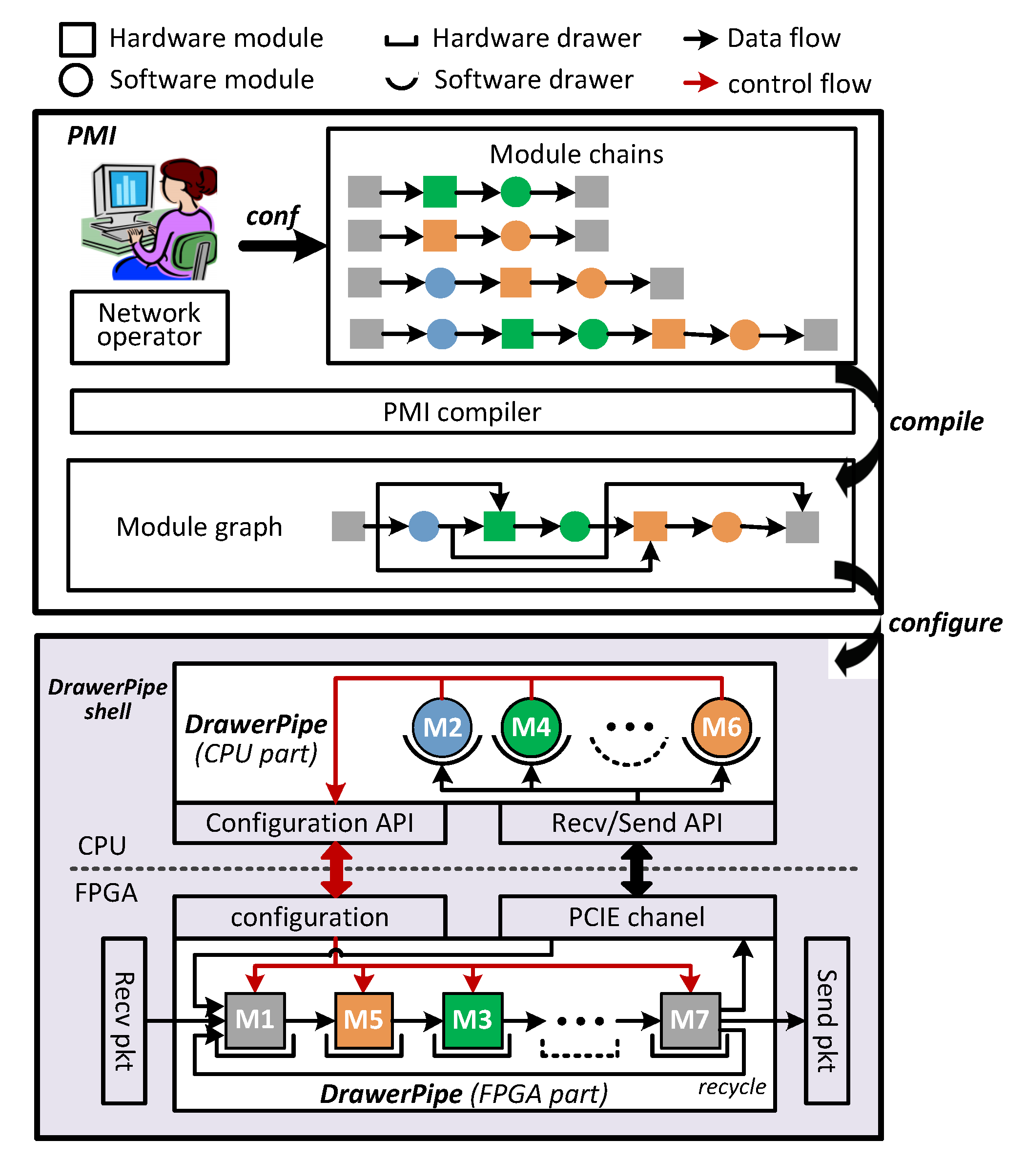
  • We present a reconfigurable network processing pipeline for SmartNIC, i.e., DrawerPipe, which abstracts packet processing into multiple “drawers” with the same interface, and provides high flexibility to add, remove, or replace modules in the “drawers” to implement custom NFs.
  • We design a Programmable Module Indexing mechanism, i.e., PMI, and a PMI compiler, which allow developers to specify the module execution order for each flow to perform required NFs.
  • We implement a DrawerPipe prototype with five reusable modules on an FPGA integrated platform, and extend four example NFs (firewall, stateful firewall, load balancer, IDS). We then evaluate the PMI by constructing multiple service chains.
Experiment results show that DrawerPipe can offload customized packet processing to FPGA with high performance up to 100 Mpps and ultra-low latency (<10 µs). NFs deployed on DrawerPipe can share the same functionalities, often significantly reducing development efforts. Compared to developing the complete logic for each NF, DrawerPipe reduces the line of code (LoC) of above four NFs by 68%. At the same time, our PMI compiler (written in Python) can quickly construct one module chain for flows that follow the same service chain. In our test, PMI compiler builds 2–32 module chains for 10K flows within 70 ms.
The rest of the paper is organized as follows: Section 2 introduces the requirements and approach of our work. Section 3 proposes the design of DrawerPipe. Section 4 shows PMI and its optimizations. Section 5 provides the experimentation and evaluation of DrawerPipe prototype, four extended NFs, and an PMI compiler. Related works on NF development are discussed in Section 6. Finally, Section 7 draws the conclusions.

2. Requirements and Approach

DrawerPipe targets designing a fast reconfigurable network processing pipeline for FPGA-based SmartNICs, which allows developers to develop and deploy multiple NFs easily on the FPGA while sharing the same functionalities. By analyzing the processing features of various commonly deployed NFs [24,25,29], we identify three key requirements for such a reconfigurable pipeline.
R1: DrawerPipe supports sharing same functionalities between NFs to prevent redundant development while ensuring the data areolation. For example, we have implemented a firewall (FW) for filtering packets from malicious hosts, and an IDS [21] to alert a system administrator after detecting intrusion, as outlined in Figure 1. To prevent redundant development, FW and IDS should share similar functionalities, e.g., header parsing and packet classification. When multiple NFs use the same module in FPGA, we should ensure the data areolation between NFs and return processed data to the right NF. For example, as shown in Figure 1c, FW gets a matched ruleID (i.e., rule a) from packet classifier, while IDS obtains another matched ruleID (i.e., rule b) even for the same flow.
R2: DrawerPipe supports FPGA/CPU co-design while using minimal FPGF-CPU communication times without affecting correctness. FPGA is no panacea, and some tasks are not suitable for FPGA [2]. Thus, DrawerPipe should support FPGA/CPU co-processing for complex NFs. Although previous work, such as ClickNP [2], has joint CPU/FPGA processing, it does not consider FPGA/CPU communication overhead as it only targets one type of NF at a time. For example, in Figure 2a, there are two NFs, i.e., IDS and an L4 load balancer (L4LB) [30] used to balance server access requests sent by external hosts. Both of them may direct packets to CPU for further processing, resulting in four FPGA-CPU communication times. The latency of PCIe-based FPGA-CPU communication ranges from 0.9 µs to 1.7 µs each time as measured in recent work [31]. Thus, DrawerPipe should reduce FPGF-CPU communication times while ensuring NF correctness, as shown in Figure 2b.
R3: DrawerPipe supports users to customize the order in which modules are executed. We found that network traffic usually traverses a sequence of NFs these days, i.e., service chain. For example, as outlined in Figure 3, while packets belonging to tenant 2 perform L4LB for balancing accessing responses, packets belonging to tenant 3 enter the FW first for filtering malicious packets. Moreover, one NF can be decomposed into multiple software or hardware modules for reusing. Thus, DrawerPipe needs to build one module execution sequence (called module chain in this paper) for each service chain. Although it is easy to customize the execution order of software modules by adjusting the order in which functions are called [32,33], the hardware pipeline cannot dynamically modify the connection relationship between modules without resynthesizing.
Our primary approach is to design a modular and reconfigurable network processing pipeline for FPGA-based SmartNICs, which allows developers to extend new NFs by inserting customized modules and specify the module execution sequence to perform required NFs. As shown in Figure 4, DrawerPipe consists of three components designed to meet all requirements:
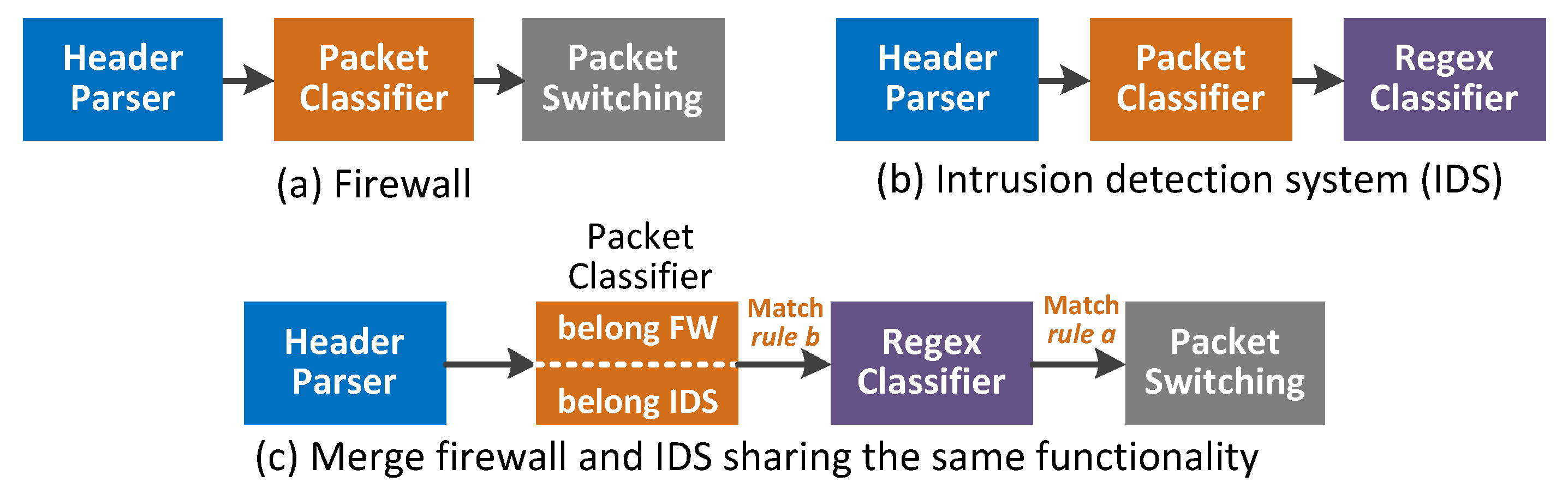
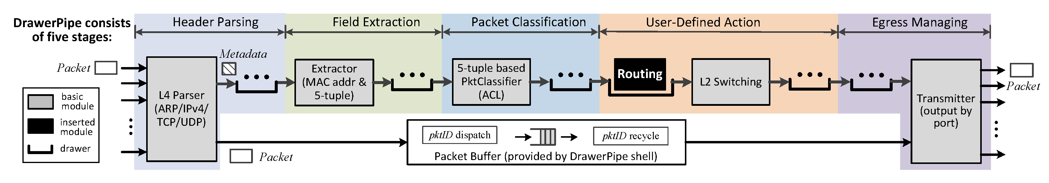
  • Modular and reconfigurable pipeline: According to the characteristics of packet processing existed in commonly deployed NFs, DrawerPipe abstract packet processing into multiple “drawers” with the same interface, and provides several highly reusable modules for low-level packet processing. DrawerPipe allows NFs sharing similar functionalities while ensuring data areolation using two methods. First, to ensure matching isolation, every rule table is divided into multiple logic tables for NFs, and each NF can only visit its own table. Second, to ensure action isolation, DrawerPipe attached metadata before each packet to carry intermediate processing result generated by modules. (R1).
  • DrawerPipe shell is the platform-related logic around DrawerPipe. DrawerPipe shell provides a set of target-agnostic APIs for receiving/sending packets, memory management, FPGA-CPU communication. Thus, developers can focus on the core application logic and write a modular code that is easily reusable (R1). In addition, we find that NF may perform three kinds of actions on packets including reading, writing, or dropping, and two independent NFs (without reading or writing the same fields) can be executed in any order. Thus, DrawerPipe merges the FPGA-CPU communication of independent NFs, and writes the intermediate processing result in the metadata. (R2).
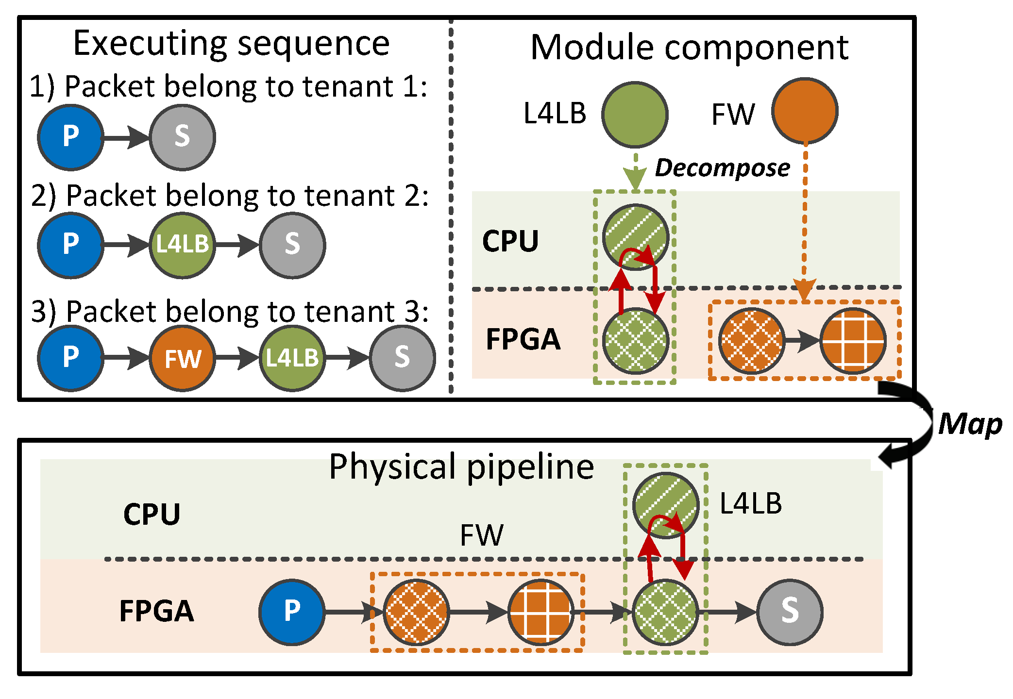
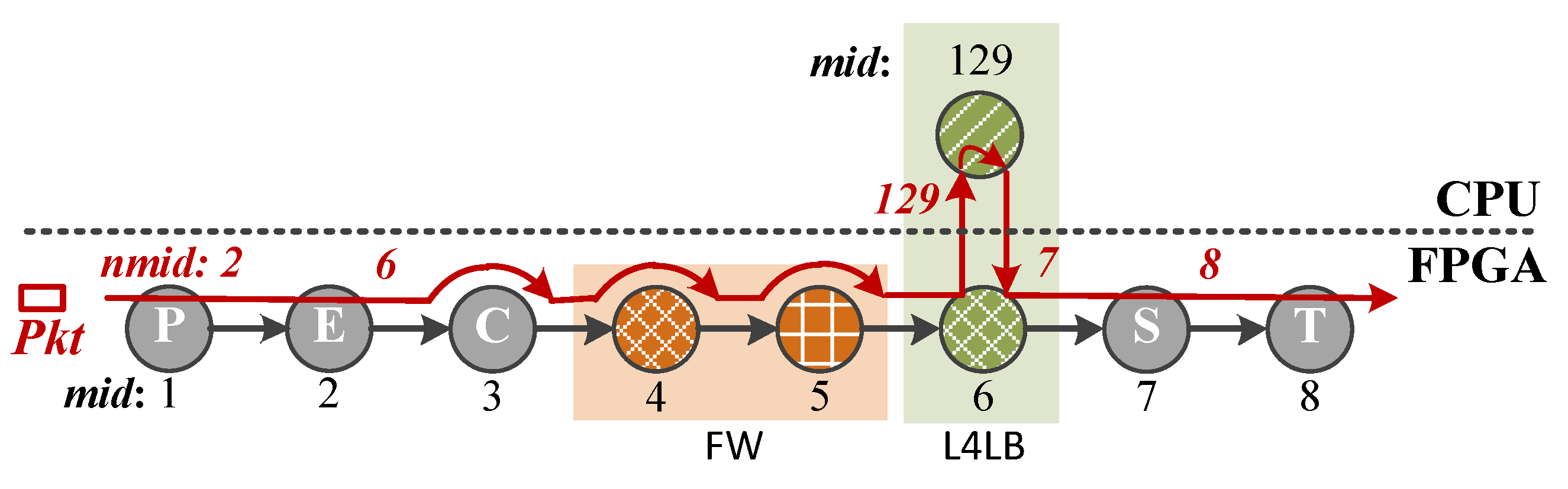
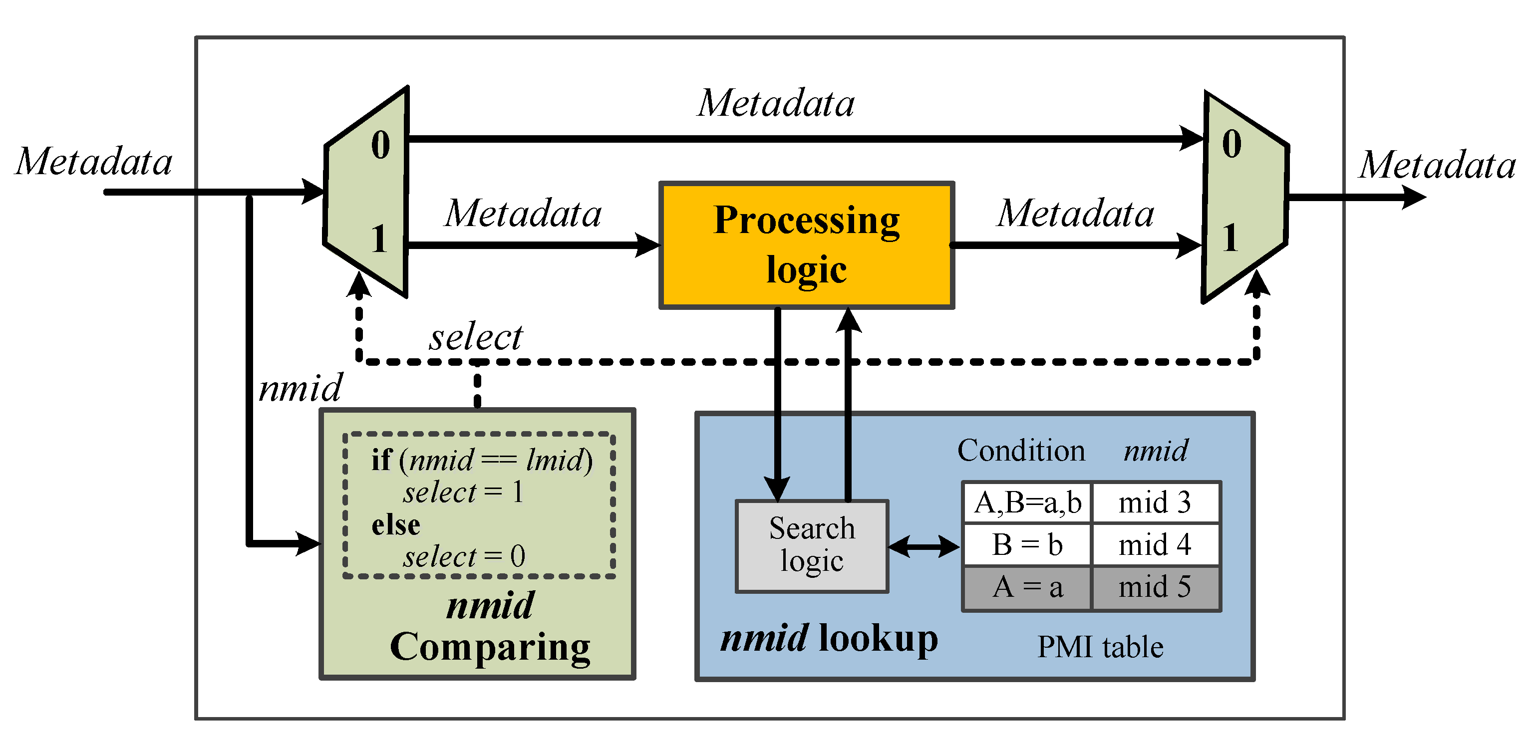
  • Programmable module indexing mechanism: Motivated by the idea of building linked list in C/C++, PMI allows users to configure the next module to process packets one by one. Thus, users can specify the module chain traversed by packets to obtain any required service chain for multiple tenants (R3). To reduce FPGA-CPU communication times, PMI steers packets through as many hardware modules as possible before passing through software ones (R2). Furthermore, we use PMI to distinguish flows or tenants that need to look up different logic rule tables for data areolation between NFs (R1).

3. Design of DrawerPipe and DrawerPipe Shell

In this section, we propose the DrawerPipe model which abstracts packet processing into multiple “drawers” with the same interface and provides five highly reusable modules for basic packet processing. Then, we present the design of DrawerPipe shell which hinds the low-level packet processing details.

3.1. DrawerPipe Model

We analyze the processing features of commonly deployed NFs [24,25,29], and find that most NFs require essential and similar processing steps. For example, most NFs parse packet headers and then classify packets based on these headers, and finally switch packets according to the destination MAC addresses. NFs can be considered as adding customized logic to these basic processing steps. For instance, we can implement an L4LB by plugging a software module allocating a server for each flow, and a hardware module searching an allocated server for each packet.
Leveraging this property, we present DrawerPipe that abstracts packet processing into five general stages, i.e., header parsing, field extraction, packet classification, user-defined action, and egress management. Each stage consists of multiple “drawers” connected by the same interface, as shown in Figure 5. Users can easily extend new NFs by inserting, removing, or replacing core application logic in the “drawers” without understanding the design details of other modules. Moreover, DrawerPipe provides five highly reusable modules (basic modules), i.e., header Parser (P), field Extractor (E), packet Classifier (C), L2 Switching (S), and Transmitter (T), for essential packet processing. Thus, modules can exchange intermediate processing results using a 256-bit metadata which includes five-tuple, MAC addresses and intermediate results (self-defined fields). In detail, if two modules have different definition of self-defined fields, we just need to modify the output metadata format of one module.
The header parsing stage is used to identify header types of packets and separate the packet header from the payload. While the payload is cached in the packet buffer, the packet header with an obtained header type is sent to the field extractor for further processing. Although the basic header parser (i.e., L4 Parser) only supports some common network protocols such as ARP, IPv4, IPv6, ICMP, TCP, and UDP, developers can easily extend custom protocols by adding new parsing modules following the basic parser without understanding or modifying existing parsing modules.
Field extraction fetches appropriate fields from the packet header according to its header type, such as extracting source and destination MAC addresses for ARP packets. The basic field extractor fetches source and destination IP addresses, IP protocol, source, and destination ports (if any) to construct a five-tuple, with source and destination MAC addresses for L2 learning and switching. As most NFs parse similar network protocols, they can share the same packet parser and only need to insert user-specific field extractors following the basic extractor for fetching required fields.
The function of packet classification is to classify or filter packets based on extracted fields, e.g., five-tuple. DrawerPipe provides a basic packet classifier based on the BitVector (BV) algorithm [34] which has predictable search latency and is suitable to be implemented in FPGAs. To trade-off hardware resource consumption and search latency, developers can replace the BV algorithm with other packet classification algorithms [35], such as decision tree (e.g., Hicuts [36], HyperCuts [37]), decomposition [38], tuple space searching (TSS) [39], or hash-based exact matching.
User-defined action is used to implement custom functionality, such as load balance. The basic module in the user-defined action stage is L2 switching, which obtains an egress port by searching the L2 forwarding table (i.e., mappings of a destination MAC address to egress port). Therefore, modification of a destination MAC address should be placed before the L2 switching, and the processing related with egress port can only be set after the L2 switching. For example, IP forwarding should be placed before the L2 switching, and measurements for counting packets sending to each egress port can only be set after the L2 switching.
The egress managing stage is used to implement packet scheduling, and drop or forward packets according to the processing actions generated during the packet classification (as ACL) or user-specific processing. DrawerPipe provides a transmitter to realize the latter functionality. NF developers can add scheduling algorithms by plugging custom modules before the transmitter. For example, we can apply Token Bucket Filtering [40] for traffic shaping, or Weighted Fair Queuing (WFQ) [41] for packet scheduling.
In detail, we take the extending L3 routing function to a basic five-stage DrawerPipe as an example. As shown in Figure 5, we add an IP forwarding module (Routing) before the L2 switching. The routing module reads a destination IP address from the metadata and performs the longest prefix match to get the next hop. Then, it uses the destination MAC address of the next hop to replace the original one, and decreases the TTL in the IP header. Finally, these modified fields will be written back to the packet in the transmitter.
To support hardware/software co-processing, users can insert either a hardware or software module in the DrawerPipe. Hardware modules can utilize massive parallelism provided by FPGAs to implement the part of packet processing that requires high performance. Software modules run as processes with high flexibility and can execute complicated logic. We extend a new NF in DrawerPipe in two steps. First, we decompose the processing logic of the NF into software and hardware parts. In each part, we share the same functionalities with existing NFs, and load customized modules in the “drawers”. Furthermore, we design a DrawerPipe shell (described in Section 3.2) to exchange packets with attached metadata between the FPGA and CPUs. As a result, software and hardware modules can share the intermediate results by reading and modifying the metadata. Second, we use PMI (described in Section 4) to link these software and hardware modules for co-processing. In addition, we leverage PMI to specify module chains traversed by packets to obtain required service chains.

3.2. DrawerPipe Shell

DrawerPipe shell is the platform-related processing logic around DrawerPipe and provides the execution environment for packet processing logic loaded in the “drawers”. It defines an API that allows hardware or software modules specified by users to access common functionality through a set of target-agnostic abstractions. Consequently, the DrawerPipe shell should meet the following requirements. First, it should provide a uniform interface that is portable across many different hardware platforms. Second, it should also provide an efficient medium to transport data across hardware and software modules. Finally, it should provide auxiliary functionalities to support receiving/sending packets from/to physical ports, buffering packets, CRC checking and calculation, attaching a receiving timestamp, and so on.
Note that developers can create a variety of potential NFs, ranging from simple ones such as firewall, to complex ones such as IDS, which needs software/hardware co-processing. To support these different use-cases, DrawerPipe shell provides hardware and software APIs. As shown in Figure 4, the hardware API includes four main functions, i.e., receiving packets from ingress ports, sending packets to egress ports, configuring registers or SRAM (tables) in hardware modules, and exchanging packets with software. The software API provides two main functions for receiving (or sending) packets from (to) hardware, and configuring hardware registers or RAM-based tables. Moreover, the functions of DrawerPipe shell are fixed, which can be implemented using IP cores provided by existing FPGA providers without frequent updates. Thus, modules in DrawerPipe do not need to modify their interface and logic when porting to other platforms.
Below, we divide the DrawerPipe shell into three major components, i.e., transceiver management, memory management, and FPGA-CPU communication.
Transceiver Management. DrawerPipe shell provides a transceiver management unit that enables DrawerPipe to use the media access control (MAC) and physical (PHY) layers specific to a target platform. The transceiver management unit uses vendor-specific protocols to receive and send packets, and provides DrawerPipe with data in a standard format. Developers do not need to understand the design details of PHY and MAC layer logic, such as gmii-rgmii conversion and CRC checking and calculation. As a result, modules in DrawerPipe are target-agnostic and portable across many FPGA platforms.
Memory Management. When packets arrive at DrawerPipe, they will be stored in the packet buffer after packet parsing, as outlined in Figure 5. The packet buffer can be designed in two ways. A straightforward approach is to use FIFO queues, i.e., one queue for each ingress port, and outputs packets in the order in which they are received. However, simple FIFO queues are not sufficient for more advanced packet processing functionalities, such as packet scheduling, which require reordering packets as they are processed.
DrawerPipe shell also provides an optional memory buffer based on SRAM. The SRAM-based memory management realizes two functions: dispatch and recycle. The dispatching function allocates a free packet block which can buffer a maximum transmission unit (MTU), and returns a unique packet identifier (packetID) when it receives a packet. Upon the completion of taking the packet out of the packet buffer, the recycling function frees the corresponding packet block, and recycles the packetID.
FPGA-CPU Communication. DrawerPipe integrates an FPGA-CPU communication channel between the hardware and software. We have designed two FPGA-CPU communication channels: one is built on top of the PCI express (PCIe) protocol [31], which is the de-facto protocol for internal communication within network devices. For example, in our previous FPGA-integrated network processing platform, such as iRouter [42], NetMagic-Pro [43], and OpenBox-S28 [44,45], we use PCIe-based channel to connect Intel FPGA (Stratix V) and Intel CPU (i7-4700eq). Another is built on top of the Advanced eXtensible Interface (AXI) [46] bus. For example, in our experiment, we use AXI-based channel to deliver message between FPGA and CPU. Based on FPGA-CPU communication channel, we provide two kinds of APIs for CPU: recv/send API and configuration API, as shown in Figure 4. The recv/send API used to exchange packets and metadata with the FPGA is the foundation for supporting FPGA-CPU co-processing. The configuration API provides functions of reading and configuring registers or SRAM-based tables in hardware modules.

4. Design of PMI

In this section, we present the strawman design of PMI and resource optimization in PMI implementation. We also design a PMI compiler to simplify the configuration of PMI table in each module.

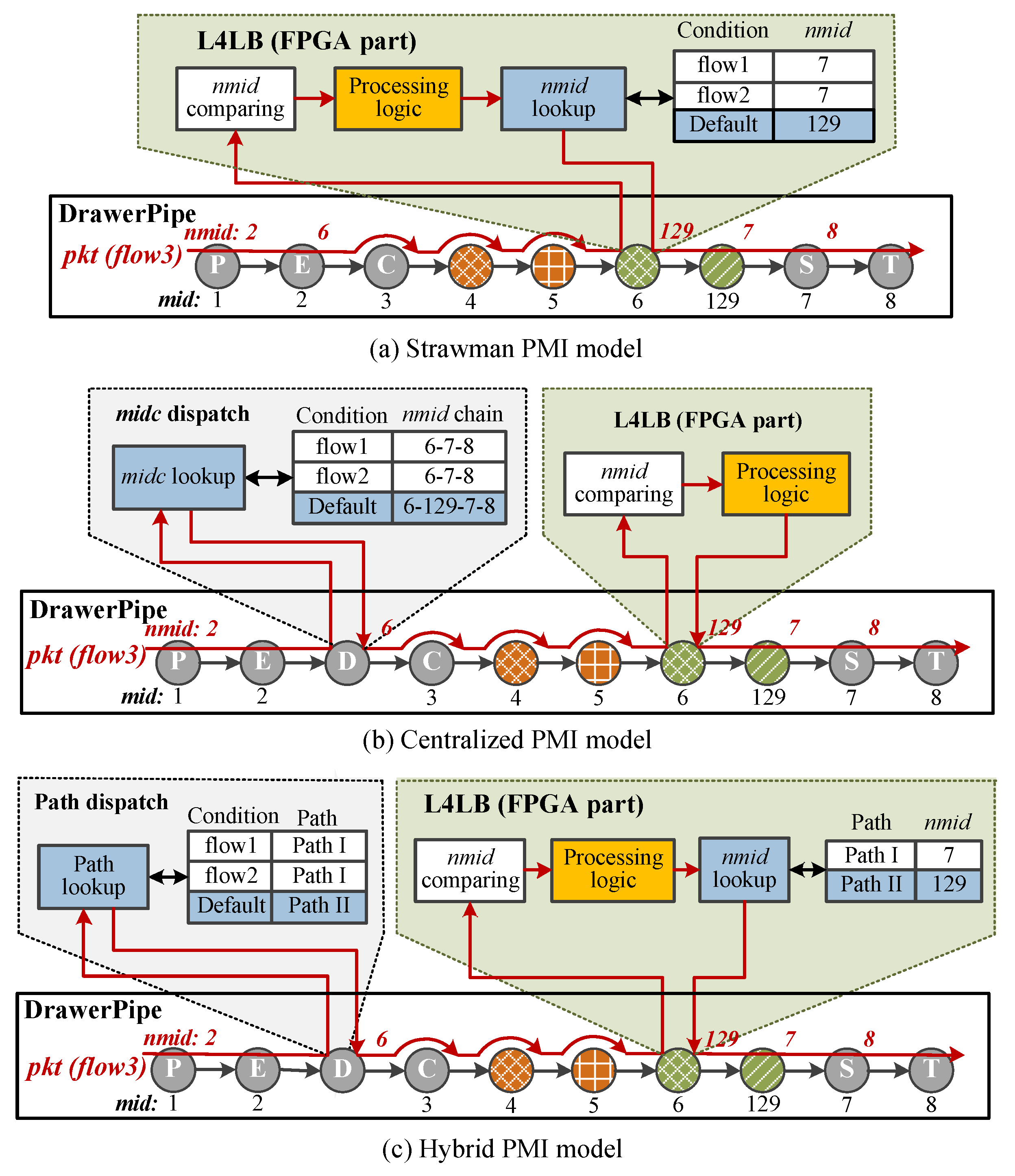
4.1. Strawman Design of PMI

Most NFs deployed in DrawerPipe are composed of multiple modules, and these NFs can share modules with similar functionalities. To perform specific NFs, we need to assign a module execution sequence for flows that follow the same service chain. Inspired by linked list in C language, PMI constructs an ordered module chain by configuring the next module to process packets for each module.
The module in DrawerPipe has a unique module identifier (mid), and PMI uses next mid (nmid) to indicate the next module following the current module. The function of nmid is similar to the GOTO command in OpenFlow [47] for skipping unrelated matching tables. Users can specify the nmid to bypass some modules that do not need to process the current packet.
PMI uses the combination of mid and nmid to construct module chains. The processing flow can be expressed as: (1) the initial module (i.e., L4 parser) receives a packet, and obtains the next module by searching mappings of flow identifier (i.e., flowID such as five-tuple) to nmid. Moreover, the obtained nmid will be filled in metadata; (2) following module compares its local mid (lmid) with the nmid carried by the metadata. If lmid is equal to nmid, the current module needs to process this packet and update the nmid; otherwise, the packet can bypass the current module; (3) repeating step (2) until the packet enters the last module of DrawerPipe (i.e., transmitter); (4) transmitter forwards the packet to egress ports when the nmid is 0 (means no succeeding module), or sends the packet back to L4 parser for performing step (1) to (4) in a new loop.
As illustrated in Figure 6, we construct a module chain, i.e., parser (P) → extractor (E) → L4LB (including a software module and a hardware module) → switching (S) → transmitter (T) for outbound TCP packets, in two steps. First, we assign one mid for each module (e.g., the mid of parser is “1”). Second, we specify nmid for outbound TCP in all traversed modules (e.g., the nmid for outbound TCP packets in the extractor is “6”). As a result, packets belong to outbound TCP will traverse parser, extractor, L4LB’s FPGA module, L4LB’s CPU module (for new flow), and transmitter before being forwarded to the egress port.
To connect software and hardware modules, we set the mid of software modules from 128, and the leverage transmitter to separate the packets sent to software modules from the packets forwarded to egress ports. Consequently, packets whose nmid is equal to or bigger than 128 are sent to software modules, and packets whose nmid smaller than 128 are returned to hardware modules.
To implement the PMI mechanism, each DrawerPipe module consists of three parts: nmid comparing logic, packet processing logic, and nmid lookup logic, as shown in Figure 7. The nmid comparing logic is relatively simple, and determines whether to process packets by comparing its lmid with the nmid conveyed in the metadata. Processing logic is realized by users to perform the application-specific function. The nmid lookup logic maintains a PMI table consisting of two fields: condition (representing flowID) and nmid. The nmid lookup logic examines packet’s flowID with entries in PMI table to find the nmid.

4.2. Optimizations of PMI

As described above, the strawman design maintains a PMI table in each module, and PMI tables are independent. In such a distributed model, packets should search multiple PMI tables to perform required NFs. A nmid lookup example is given in Figure 8a, in L4LB’s FPGA module, the first packet of f l o w 3 matches the default entry and then updates its nmid to 129.
Although it is easy to implement a PMI table and write a reusable lookup logic based on a hash algorithm, the disadvantages of the strawman PMI model are also obvious. First, as the number of flows grows, maintaining a PMI table in each module consumes lots of memory resources and introduces additional lookup delay due to hash conflict. Second, inserting a new module may need to modify the PMI table (e.g., adding matching entries or changing matching fields) of all upstream modules, which can be complicated. For instance, in Figure 8a, if there is no FW in the current pipeline and we want to add an FW after the packet classifier to filter malicious flows, we need to find the upstream modules (i.e., extractor, packet classifier) and configure their PMI tables to direct traffic to the modules of FW.
To solve the problems above, we present two optimized PMI models, i.e., centralized PMI and hybrid PMI models. While the centralized PMI model specifies the module execution sequence in a centralized module, the hybrid PMI model compresses the same execution sequence as a path, and assigns nmid by searching path-nmid mappings in each module.

4.2.1. Centralized PMI Model

As shown in Figure 8b, compared with maintaining a PMI table in each module, centralized PMI maintains only one mapping table in the mid-chain (midc) dispatcher (D) after the extractor. The mapping table includes two components, i.e., condition and mid chain. The mid chain consists of a list of modules that should be traversed by packets. Therefore, the received packet is sent to the midc dispatcher, and obtains a mid chain by examining its flowID with entries in the midc dispatch table. The following modules only need to check the mid chain, without maintaining a condition-nmid mapping table like strawman PMI model.
The processing flow of modules after midc distributor can be described as: (1) comparing the module’s lmid with the header of mid chain carried by metadata. If the lmid is equal to the head mid, this module should process the current packet; otherwise, output the current packet without processing; (2) updating the mid chain by popping out the head mid after processing.
Still, taking the first packet of f l o w 3 in Figure 8b as an example, the packet matches the default entry in the midc dispatcher and obtains a mid chain as 6 129 7 8 . That is, the current packet needs to pass through four modules (i.e., L4LB’s FPGA and L4LB’s CPU modules, switching and transmitter) after the midc dispatcher. When mid chain reaches the end of the list, the packet can jump out of the DrawerPipe and be forwarded or discarded according to the output port in the metadata.
The centralized PMI model does not maintain a PMI table in each module, which can save a lot of storage resources and time used for performing PMI table lookups. However, it is hard for hardware to maintain a long and variable mid chain in the midc dispatch table and metadata. Moreover, it causes a waste of resources if we distribute a fixed space in midc table and metadata for the longest mid chain.

4.2.2. Hybrid PMI Model

The hybrid PMI model combines the advantages of both centralized and strawman models. As outlined in Figure 8c, the hybrid PMI model has two different characteristics. First, we compress the same module execution sequence into one path, which can save a lot of memory resources by avoiding recording one module chain for each flow. For example, in Figure 8c, f l o w 1 and f l o w 2 have the same module execution sequence, and we use path I to represent this sequence. As a result, a path dispatcher in hybrid PMI model saves a mapping of condition to path identifier (pathID) instead of a variable mid chain. Second, the hybrid PMI module maintains pathID-nmid mappings (namely path table) in each module.
Taking Figure 8c as an example, the first packet of f l o w 3 matches the default entry in the path dispatcher and obtains path II, which means the packet should traverse modules represented by Path II. The following modules only need to search the path table to obtain the nmid, such as the nmid of path II in L4LB’s FPGA module being 129 (i.e., L4LB’s CPU module). Consequently, the current packet will be sent to L4LB’s CPU module after the processing of L4LB’s FPGA module.
The processing flow of hybrid PMI model can be described as: (1) DrawerPipe receives a packet, and sends it to a parser and extractor for basic packet processing; (2) then, path dispatcher gets this packet and examines its flowID with condition−path mappings to find a pathID and an initial nmid. The pathID and initial nmid will be filled in metadata; (3) succeeding modules compare their lmid with the nmid. If they are equal, the current module needs to process this packet and update nmid by searching the pathID−nmid mappings; otherwise, packet could bypass the current module; (4) if nmid is 0, this packet has already been processed by all modules, and can jump out of the pipeline.
There are two advantages in the hybrid PMI model. First, we merge the same module chain into a path, which is more memory-efficient than the centralized one. Second, as pathID is ordered from zero, modules can directly use pathID as the index to search the path-nmid table without any hash conflict. Consequently, we adopt the hybrid PMI model in DrawerPipe.

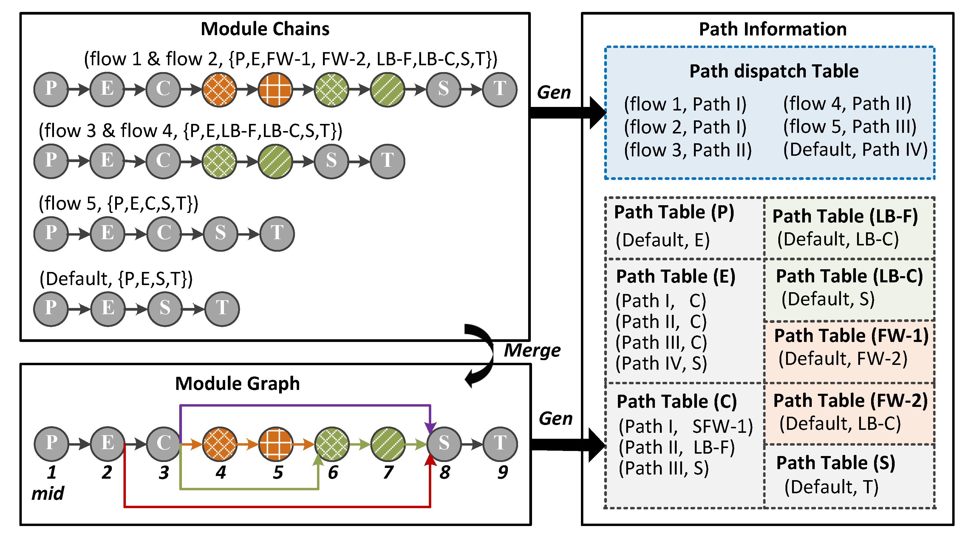
4.3. PMI Compiler Design

The intention of designing a PMI compiler is to transform service chaining intent into module connections, i.e., the configuration of path dispatch and path tables. As NFs deployed in DrawerPipe are composed of multiple modules, we can use module chains to represent service chaining intent.
Module chains are described in a simple script consisting of two-tuple, i.e., (condition, {module name}), as shown in Figure 9. The condition (i.e., flowID) consists of one or multiple matching fields, such as five-tuple. Each condition corresponds to a list of modules (i.e., {module name}), which represents the execution order of modules. In Figure 9, ( f l o w 1 , {P, E, FW-1, FW-2, LB-F, LB-C, S, T}) means packets belonging to f l o w 1 pass through parser, extractor, FW-1, FW-2, LB-F, LB-C, switching and transmitter in order.
Based on the above abstraction of module chains, the PMI compiler transforms module chains into configuration content of the path dispatch table and path table as follows. First, the PMI compiler generates a module graph based on module chains, as outlined in Figure 9. Since DrawerPipe has only one physical processing pipeline, we merge multiple module chains to this pipeline described by module graph. Referring to Algorithm 1, we firstly initialize freeMid and moduleGraph. Then, in pseudocode 3–13 lines, we traverse all module chains stored in moduleChainArray (reading from the script), and dispatch a unique mid for each module without repetition. Meanwhile, we append these modules to moduleGraph. Similarly, we dispatch each different module list a pathID in the pseudocode 12 line. Finally, in pseudocode 14–20 lines, we examine all possible downstream modules for each module, and record them in the node array (described as m o d u l e G r a p h [ n o d e ] ).
Second, the PMI compiler generates path information (configuration of path dispatch and path tables) based on module chains and the module graph, as shown in Figure 9. We find that each module chain corresponds to an entry in the path dispatch table, and each path corresponds to an entry in the path table. Moreover, if there is only one nmid in path table, we can merge these entries into one default entry. For instance, the default nmid of the parser is the extractor. Leveraging these observations, the PMI compiler generates path information in two steps, described in Algorithm 2: (1) In pseudocode 1–4 lines, we record a condition to pathID mapping for each module chain in the path dispatch table array ( p a t h D T b [ i ] ). (2) Then, in pseudocode 5–13 lines, we fill the pathID to nmid mapping for each moduleGraph module and merge the same nmid to a default entry.
Algorithm 1 Generate module graph based on module chains
1:  f r e e M i d 1
2:  m o d u l e G r a p h NULL
3: for i = 0 to Length( m o d u l e C h a i n A r r a y ) do
4:   n o d e = m o d u l e C h a i n A r r a y [ i ] . f i r s t N o d e
5:  while n o d e NULL do
6:   if n o d e not in m o d u l e G r a p h then
7:     n o d e . m i d f r e e M i d + +
8:     A p p e n d ( m o d u l e G r a p h , n o d e )
9:   end if
10:    n o d e = n o d e . n e x t N o d e
11:  end while
12:  AssignPathID m o d u l e C h a i n A r r a y [ i ] )
13: end for
14: for i = 0 to Length( m o d u l e C h a i n A r r a y ) do
15:   n o d e = m o d u l e C h a i n A r r a y [ i ] . f i r s t N o d e
16:  while n o d e NULL do
17:    m o d u l e G r a p h [ n o d e ] [ i ] . n m i d = n o d e . n e x t N o d e . m i d
18:    n o d e = n o d e . n e x t N o d e
19:  end while
20: end for
Algorithm 2 Generate path information based on module chains and module graph
1: for i = 0 to Length( m o d u l e C h a i n A r r a y ) do
2:   p a t h D T b [ i ] . c o n d i t i o n m o d u l e C h a i n A r r a y [ i ] .
    c o n d i t i o n
3:   p a t h D T b [ i ] . p a t h I D m o d u l e C h a i n A r r a y [ i ] .
    p a t h I D
4: end for
5: for n o d e in m o d u l e G r a p h do
6:  if n o d e h a s o n l y o n e n e x t n o d e then
7:    p a t h T b [ n o d e ] [ d e f a u l t ] n o d e [ 0 ] . n m i d
8:  else
9:   for i = 0 to Length( m o d u l e C h a i n A r r a y ) do
10:     p a t h T b [ n o d e ] [ m o d u l e C h a i n A r r a y [ i ] . p a t h I D ] =
    m o d u l e G r a p h [ n o d e ] [ i ] . n m i d
11:   end for
12:  end if
13: end for

5. Evaluation

Based on the DrawerPipe model, we implemented a basic five-stage pipeline on a Xilinx FPGA integrated network processing platform that consists of a Zynq-7000 SoC chip [46], 4 GB DDR3 DRAM, and four 1 Gbps ports. In more detail, the Zynq-7000 SoC chip we used integrates an FPGA chip and two ARM Cortex-A9 processors. The FPGA chip has 53200 Slice LookUp Tables (Slice LUTs), 106,400 Slice registers, and 140 Block RAM tiles (i.e., 2520 Kb).
Below, we evaluate the DrawerPipe model and PMI mechanism from three aspects. First, we have extended four example NFs based on DrawerPipe to demonstrate the flexibility of DrawerPipe model. Second, we tested the performance and resource consumption of key modules in DrawerPipe. Third, we implement and compare resource consumption of three PMI models, and construct multiple module chains to evaluate the performance of our PMI compiler.

5.1. Applications

To evaluate the flexibility of DrawerPipe model, we have extended four example NFs based on the DrawerPipe model. These NFs include five-tuple based firewall, stateful firewall, L4 load balancer, and IDS. The hardware modules are written in Verilog, and the software modules are implemented using C. Using these case studies, we demonstrate that the DrawerPipe model supports diverse applications and enables modular development by allowing developers to focus on the core application logic.
Table 1 summarizes the LoC of four NFs developed in two methods, i.e., individual and reusing. As mentioned in Section 2, individual development often requires developers to write complete packet processing code for each NF. Therefore, we adopt the reusing method to simplify NF development by reusing the same functionalities with other NFs and five basic modules provided by DrawerPipe. As shown in Table 1, compared with individual NF development, the reusing method only requires writing 12.4–54.1% code for application-specific logic based on the DrawerPipe framework. Moreover, our experience also shows that DrawerPipe provides high flexibility of adding, removing, or replacing modules to implement custom NFs.
A1. Firewall. The function of the firewall is to filter the specific flow whose flowID matches the pre-configured filtering rules. The rules of the firewall may have masks to filter one kind of packet. For instance, if we want to drop TCP packets, we can set the filtering rule as (*, *, 6, *, *) where IP protocol is equal to “6” and other fields of 5-tuple can be any value.
As DrawerPipe provides the basic packet processing functionalities of parsing, filed extraction, and packet classification, we can reuse these basic modules and add an action table to implement the firewall. The action table maintains an action (drop or accept) for each rule in the packet classifier. Consequently, if one packet hits a rule in packet classifier and gets the matched index, the firewall will drop or accept this packet according to the action directed by the index.
A2. Stateful firewall (SFW). Some NFs process packets based on connections, not just packets, such as stateful firewall and L4 load balancer. Our SFW maintains a list of IP addresses for internal hosts, and only allows the TCP connection request whose source IP address belongs to this IP address list. Consequently, SFW allows outbound TCP connections, but rejects inbound ones. However, the external host is allowed to send packets to the internal host through the established TCP connection. Thus, SFW needs to track the status of all active connections, including both client and server connection statuses, such as requested or established, sequence and acknowledgement numbers, and window size scaling factor.
We implement SFW by plugging two hardware modules between packet classifier and L2 switching. One module is used to examine the source IP address of packets with the internal IP address list for filtering inbound TCP connections. The other module tracks TCP connections, and drops invalid packets according to the connection status. SFW discards packets in three situations. First, the packet’s sequence number exceeds the safe range of a received acknowledgement number (occurring in replay attacks [48]). Second, packets do not belong to the current status, e.g., receiving an FIN packet in the requested status which waits for an SYN-ACK packet). Third, packets match a closed or time-out connection. Thus, we maintain a timer for each connection, and close the connection when its timer expires (e.g., out timeout is set to 100 sec).
A3. L4 load balancer (L4LB). Load balancer has been widely used in modern network, such as loading traffic to different paths in a multi-path environment, sending accessing requests to distinct servers to balance the workload in datacenter. Our L4LB is the latter, which balances the workload by sending more requests to servers that have lower CPU usage while guaranteeing the same flow processed by the same server based on 5-tuple.
L4LB also needs to track TCP status, e.g., assigning a destination server for each new connection, replacing destination (or source) IP address for established connections, and deleting the mapping of flowID to a destination server when the connection is closed. In our implementation, we insert a mapping searching module after the SFW, and share the connection management function with SFW. The mapping searching module is used to examine 5-tuple of packets with mappings to find the destination server. In addition, we developed a software module to communicate with servers to obtain their CPU usages, and to dispatch an appropriate server for each new connection to balance workload.
A4. Simplified IDS. Snort [21] is an open source intrusion detection system developed by the C language. The processing flow of snort can be decomposed into four steps. First, Snort receives packets from the network interface card (NIC) based on libpcap or DPDK [10]. Second, it parses received packet and extracts five-tuple according to the header type. In particular, it extracts source and destination IP addresses, IP protocol, ICMP type and code for ICMP packets. Third, it examines these extracted fields with pre-configured rules, and executes the last step if they match. Finally, it performs option fields lookups which consist of exact matching and regular expression matching. If they match, it will generate alarm information according to the processing action.
Due to the limited performance and high processing delay of Snort software, it is difficult to achieve line rate processing of 10 Gps. For this reason, we offload part of the processing of Snort to FPGA for acceleration, including packet parsing and packet classification used for rule matching based on 5-tuple, and left option matches on software. In our implementation, we added a hardware module after the packet classifier to direct specific flows to software, and developed a software module to perform option fields lookups to filter malicious packets. Finally, hardware and software modules interact with packet and control information through the DrawerPipe shell.

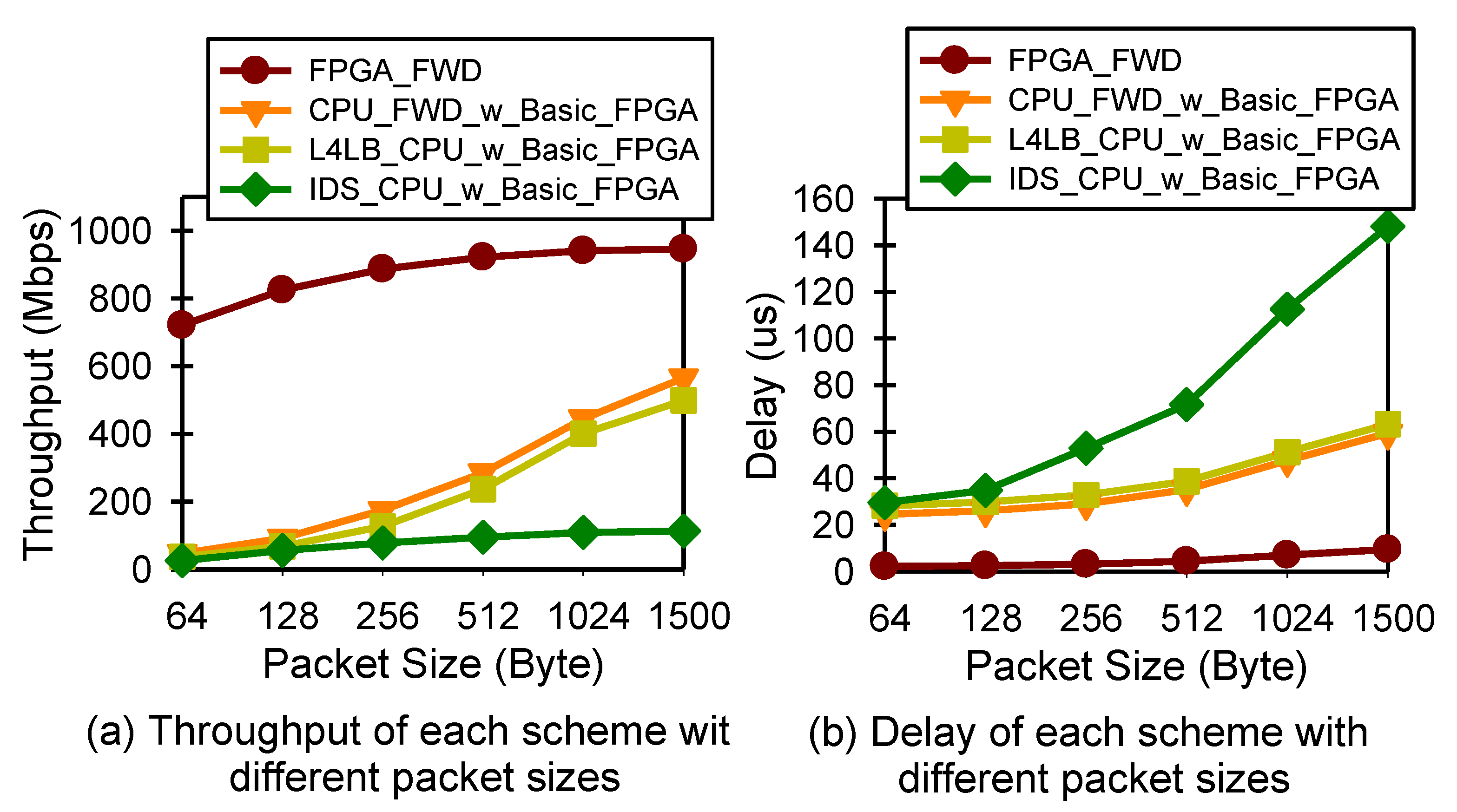
5.2. Performance and Resource Utilization
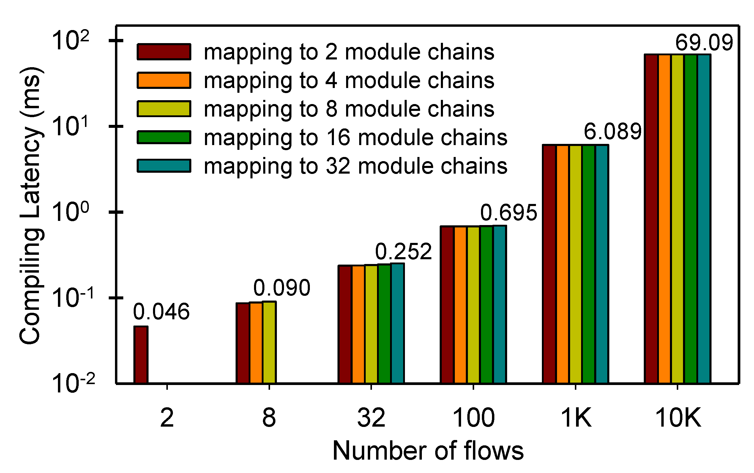
In this experiment, we evaluate the performance and resource utilization of key modules in DrawerPipe, including five basic modules and application-specific modules for implementing the four NFs above. Since our platform does not provide multiple 10 Gbps interfaces, we test the performance of these modules using simulation by Xilinx Vivado (the version is 2017.04) [27] and Intel Quartus (the version is Quartus prime 16.0.2) [28], which have been common choices in previous hardware tests [49,50]. We further investigate the performance of software modules contained in four NFs on our platform.
Table 2 presents the key modules we have implemented in DrawerPipe. The listed modules include five basic modules: (L4_Parser, Extractor, Packet Classifier, Switching, Transmitter), two kinds of packet buffers (based on FIFO and SRAM), and six application-related modules (Firewall, Stateful Firewall, L4LB_FPGA, L4LB_CPU, IDS_FPGA, IDS_CPU). We first test the Maximum clock Frequency (FMax) of each module, and the lowest one is 232.88 MHz, as shown in Table 2. Thus, in the following simulation experiment, we test the throughput and latency under the clock frequency of 200 MHz, which is a typical clock frequency of FPGAs [2]. For the top part of Table 2, the module needs to touch every byte of a packet. We show the throughput in Gbps. The modules in the bottom part of the table, however, process only the packet header (metadata). Therefore, it makes more sense to measure the throughput using packet per second (pps). Although most modules can be completely pipelined, i.e., it can input search key and output result of every clock, some modules cannot process one metadata every clock, such as extractor processes with one metadata every two clocks, and can only achieve 100 Mpps. The width of Metadata we adapt is 256 bits, which includes five tuple.
We also show the processing latency of each module in Table 2. As we see, this latency is low: the mean is 8 clocks (equal to 40 ns at 200 MHz), and the maximum is merely 26 clocks (Stateful firewall). We note that the delay is not related to the throughput, as modules can leverage FPGA’s parallelism to process multiple packets at the same time. For instance, a BV-based packet classifier incurs a long delay (i.e., 17 clocks in our design) to find the matched rule with the highest priority. However, this packet classifier can be completely pipelined, i.e., it can input search key and output matched rule every clock.
We evaluate the three types of resource utilization for each module, including Slice LUTs, Slice registers, Block memory, and summarize the result in the last three columns of Table 2. The utilization is normalized to the capacity of the FPGA chip. We can see that most modules use only a small amount of logic and register resources. This is reasonable as most operations on packets are simple. Packet classifiers have moderate usage of logic and register resources because they have bigger logic, such as shift operation for updating match rules. The block memory usage, however, heavily relies on configurations of modules. For example, the block memory usage grows linearly with the number of rules supported in the packet classifier. Overall, our FPGA chip has sufficient capacity to support multiple simplified NFs by assembling above modules. Thus, a developer can use the onboard DDR memory to get enough storage space at the expense of introducing additional access delay.
Since servers in the datacenter are always virtualized to deploy multiple virtual machines, we encountered a problem that FPGA (i.e., Xilinx Zynq-7000 SoC chip we use) has limited resources to support tens of thousands of flows (or rules) when we implemented NFs. We find that there are three methods to support more flows (or rules). First, we can use high-capability FPGAs such as Xilinx Virtex UltraScale series and Intel Stratix 10 series, which have 20× memory resources than Xilinx Zynq-7000 SoC chip. However, the maximum flows (or rules) that can be maintained by onboard SRAM is less than the worst case even if we use the most advanced FPGA chip. Second, we can use onboard DDR memory (DRAM) to get enough storage space at the expense of introducing additional access delay. As the total number of supported flows or rules is limited only by the DRAM capacity, it is sufficient to support O(1M) flows and O(100K) rules with 4 GB DDR memory. Third, similar to processing of SDN, we can maintain part of the flows on FPGA’s SRAM and send packets that miss the flow table to CUP for processing. This method uses DDR to storage flows (or rules), which has good scalability. However, compared to SRAM-based strategy, two DRAM-based methods incur additional access latency. To maintain a high performance, we can use SRAM as an L1 cache and use DRAM to store the left flows (or rules). At the same time, we should adopt an efficient replacement strategy to maintain a high SRAM hit rate to reduce the DRAM access times. In fact, considering scalability and implementation complexity, we adopt the third approach, i.e., maintaining a part of flows on FPGA’s SRAM and sending packets that miss the flow table to CUP for processing. In addition, we can also use a high-capability FPGA to store more flows (or rules) in the next work.
We also evaluate the power of four NFs (i.e., firewall, stateful firewall, L4LB, IDS) integrated project with a 40-rule packet classification. The result shows that the total power is 2.139 w, consisting of 0.050 w for clocks, 0.089 w for signals, 0.0058 w for logics, 0.018 for BRAM; 0.0055 w for MMCM, 0.154 w for I/O, 1.544 w for PS7 and 0.172 w for Device static. Then, we test the schematic RTL of a four-NF integrated project. The results show that there are six cells, 262 I/O ports, and 343 Nets in the entire SoC project.
Furthermore, we evaluate the performance of software modules in two NFs (i.e., L4LB and IDS) on our platform. As mentioned above, the function of L4LB_CPU module is to dispatch a relatively idle server for each new connection, and IDS_CPU module is used to inspect packet payload with pre-configured rules. In the performance test of the L4LB_CPU module, we set the number of servers available for selection to 10, and configure the maximum number of flows to 1 K. That is, we support a load balance of 1 K active flows for 10 servers. We configure IDS_CPU module with almost 2 K option rules commonly used in the Snort.
In this experiment, we connect our platform with an IXIA emulator [51] which can generate packets with different size. The packets sent by IXIA pass through L4LB_CPU or IDS_CPU module and then return to IXIA. Consequently, we subtract the timestamps of sending and receiving packets to get processing delay, and calculate the throughput by counting the number of packets received per second. To better illustrate the performance of L4LB_CPU module, we also test the performance of L2 forwarding packets by FPGA (FPGA_FWD) and L2 forwarding packets by CPU (CPU_FWD), and use them as a reference. Moreover, in the scheme of L4LB_CPU_w_Basic_FPGA, the function of allocating server for new flows is implemented on CPU while the basic processing such as header parsing is implemented on FPGA.
Figure 10a shows the throughput with different packet sizes. With all sizes, FPGA L2 forwarding can almost achieve line rates, i.e., 764 Mbps with 64 B packets and 981 Mbps with 1500 B packets. This is reasonable as two packets have to maintain an Interframe Gap (IFG), and sending smaller packets wastes more bandwidth. CPU straight forwarding, however, achieves only a maximum of 565 Mbps, and the throughput decreases as packets become smaller. This is because, with a smaller size, the number of packets needing to be processed increases. While L4LB_CPU_w_Basic_FPGA module can achieve 37 Mbps with 64 B packets and 499 Mbps with 1500 B packets, IDS_CPU_w_Basic_FPGA can only achieve 26 Mbps and 113 Mbps when packet sizes are 64 B and 1500 B, respectively. The reason is that the packet processing of L4LB_CPU module is relatively simple, but IDS_CPU module needs to perform much more complicated logic such as regular expression matching. In addition, since IDS_CPU module inspects every byte of a packet, its throughput does not increase significantly as the packet size increases. Fortunately, since the number of packets that need to be sent to the CPU is small, such as L4LB only needing to send the first packet of each flow to CPU, using two low-power ARM cores is enough to handle these exception packets.
Figure 10b shows the latency with different packet sizes. Again, FPGA L2 forwarding yields low latency smaller than 10 µs, but CPU L2 forwarding incurs a larger latency up to 60 µs. For the same reason, the latency of L4LB_CPU_w_Basic_FPGA is a little more than CPU L2 forwarding, but the latency of IDS_CPU_w_Basic_FPGA is large and increases significantly as the packet size increases. We note that the difference between FPGA and CPU L2 forwarding delay is mainly caused by DMA, and the difference between CPU L2 forwarding and L4LB_CPU_w_Basic_FPGA or IDS_CPU_w_Basic_FPGA delay is the overhead for implementing application-related processing.

5.3. PMI Evaluation

In this subsection, we compare the resource consumption of three PMI models and evaluate the performance of our PMI compiler based on hybrid PMI model.
In this experiment, we implement three PMI model, i.e., strawman, centralized, and hybrid. The PMI tables in all models are implemented using Cuckoo Hashing (with two hash buckets) and contains 2K entries that match against flow 5-tuples. We fix the number of total flows to 1K and construct four kinds of module chains outlined in Figure 9. Table 3 shows three kinds of resource utilization in each PMI model. We can see that all schemes use only a small amount of logic and register resources and have a moderate usage of block memory to maintain PMI tables and buffer packet/metadata. The resource utilization of nmid lookup in each scheme is almost equal. However, strawman needs to maintain a nmid lookup in each module except the parser and the transmitter, which consume more resources than the centralized and hybrid models. Moreover, as mentioned above, the centralized model needs to maintain a module chain for each flow, which also uses more block memory resources than the hybrid one. Therefore, the total block memory used by strawman is centralized PMI models are 4.15× and 1.20× more than the hybrid one.
In addition, we evaluate the performance of a PMI compiler on a machine with Intel core i7-8550U CPUs (1.80 GHz, 8 cores in total), 16 GB of RAM. Figure 11 shows the compiling latency of generating 2–32 module chains combining the four NFs above with the different number of flows. We can see that the compiling latency grows linearly as the number of flows increase. However, the difference between constructing 2–32 module chains for the same number of flows is very small. For instance, the compiling latency of mapping 100 flows to 2 and 32 module chains are 0.681 ms and 0.695 ms, respectively. This is because most of the time is spent reading module chains described in the script and generating the corresponding module graph, and the time consumed by generating configuration rules for path dispatch and path tables is small.

6. Related Work

Software NFs have perfect flexibility and can implement many complicated packet processing. Recently, many software systems have been designed to implement various types of NFs [25,29,33,52]. However, software NFs have two fundamental limitations: limited capacity and highly variable latency. However, most software systems exploit the multi-core parallelism in CPUs to achieve close to 10 Gbps throughput per machine, and scale out to use more machines when higher capacity is needed. While software NFs can scale out to provide more capacity, doing so adds considerable costs in both capital expenditure and operating expense [2,8]. Some other optimizations, such as bypassing kernel protocol stacks (e.g., DPDK [10]) and processing a vector of packets at a time (e.g., VPP [11]), can greatly increase the throughput of packet processing, but there are still large and fluctuating processing delays [8].
To accelerate software packet processing, recent work has proposed using GPUs [53], NPs [54], or FPGAs [2,55,56,57]. GPU leverages batch operations to improve throughput, but it has a high delay. For example, the forwarding latency reported in [53] is about 200 us. NP is specialized to handle network traffic, resulting in portability difficulties. In contrast, FPGAs are more power-efficient and have a lower delay than GPUs [58,59], and have better reconfigurability than specialized NFs [2]. Therefore, FPGA has be popularly used to accelerate network processing, such as scheduling [60], software-defined network (SDN) [14,44,55,61,62], NFs [2,8,56], and network applications [63,64,65,66].
Recent work presents the idea of developing NFs on FPGA-based SmartNICs to accelerate specific NFs while maintaining high flexibility [2,8,67]. However, the state-of-the-art SmartNIC framework, i.e., AccelNet [8], is carefully designed to accelerate specific NFs for datacenter operators, which require professional hardware design ability. Thus, without rich experience and expertise, it is still challenging for most tenants to rapidly deploy their NFs on the SmartNICs. Moreover, there is limited work on orchestrating the performing order of NFs (i.e., service chaining), on the same FPGA/CPU co-processing platform.
There is also some related work presented to reduce the difficulty of developing NFs with FPGAs [2,14,15]. The core idea of these methods is describing NF in high-level languages (e.g., C/C++), and then compiling it to hardware code using High-Level Synthesis (HLS) tools (e.g., Xilinx Vivado HLS [27] or Altera OpenCL SDK [28]). Existing HLS tools, however, are still difficult to address data hazards, resulting in low processing performance and high resource consumption [8,15]. Moreover, the current work of developing NFs using high-level languages, e.g., ClickNP [2], EMU [14], focuses on accelerating individual NF, and lacks the way of deploying multiple NFs on one FPGA where NFs should share same functionalities while ensuring the data areolation. In addition, other work presents programmable architecture, such as PISA [18], abstracts packet processing into multiple Match-Action Tables (MATs) [19], and mapping network processing described in P4 [20] into these MATs. Currently, PISA focuses on processing packet in hardware, and it does not support software/hardware co-processing. In DrawerPipe, software module is equivalent to the hardware module, and both can be designed for data-plane processing. For example, limited by FPGA resources, we only offload part of the processing of Snort to FPGA for acceleration, including packet parsing, packet classification used, and left option matches on software. Therefore, a packet may be processed by hardware and software modules.
DrawerPipe is compatible with two methods using high-level programmable language, i.e., modules generated by HLS tools or MATs can be loaded in the “Drawer” to construct NFs with handwritten modules. Currently, although most NFs are still manually written in hardware description languages (HDL) in the datacenter [8], we may use high performance modules generated by HLS tools with the optimization of compilers in the future.

7. Conclusions and Future Work

In this paper, we present DrawerPipe, a modular and reconfigurable network processing pipeline for FPGA-based SmartNICs. DrawerPipe abstracts packet processing into multiple “drawers” connected using the same interface, and allows users to extend NFs by loading their core processing logic in the “drawers” while reusing the existing modules. As most NFs carry out similar processing stages, DrawerPipe also provides five highly reusable modules for basic packet processing. Furthermore, DrawerPipe adopts a programmable module indexing mechanism, namely PMI, to connect software and hardware modules for FPGA/CPU co-processing and to construct various module chains to perform required NFs for different flows. Although we need to redefine Metadata when change supported protocols (e.g., replacing IPv4 with IPv6), it is easy to extend the width of Metadata. In DrawerPipe, we only need to redefine the width of Metadata and modify the logic of extracting fields from Metadata for each module, without redesigning the core application logic. Moreover, we have designed an IPv6-based DrawerPipe, and implemented a switch supporting IPv6-based Segment Routing (SRv6) [68], which can be used to construct multiple overlay networks for different services. Our practice shows that DrawerPipe is flexible as it can rapidly reconfigure FPGA to construct specific NFs and achieves high performance using well-designed modules.
However, there are also some avenues that suggest improvements in scalability. For example, current SBV-based packet classification and SRAM-based packet buffer consume a lot of on-chip memory resource. Our future work will focus on reducing the resource consumption by optimizing or redesigning packet classification algorithm, such as employing the TSS [39] algorithm to replace the SBV algorithm. We will also extend the API of DrawerPipe shell for developers to use the onboard DDR memory to buffer packets or rules with an efficient replacement strategy.

Author Contributions

Conceptualization, J.L. and Z.S.; Methodology, J.L. and Z.S.; Hardware and software, J.L. and J.Y.; Validation, J.L., J.Y., X.Y., and Y.J.; Investigation, X.Y. and W.Q.; Writing—original draft preparation, J.L.; writing—review and editing, Y.J. and Z.S.; funding acquisition, Z.S. and W.Q. All authors have read and agreed to the published version of the manuscript.

Funding

This work was supported in part by grants from the National Natural Science Foundation of China (No. 61802417 and No. 61702538), and the Scientific Research Program of the National University of Defense Technology (No. ZK18-03-40 and No. ZK17-03-53).

Acknowledgments

The authors would like to thank the anonymous reviewers for their valuable feedback.

Conflicts of Interest

The authors declare no conflict of interest.

References

  1. Firestone, D. VFP: A Virtual Switch Platform for Host SDN in the Public Cloud. In Proceedings of the 14th USENIX Symposium on Networked Systems Design and Implementation (NSDI 17), Boston, MA, USA, 27–29 March 2017; pp. 315–328. [Google Scholar]
  2. Li, B.; Tan, K.; Luo, L.L.; Peng, Y.; Luo, R.; Xu, N.; Xiong, Y.; Cheng, P.; Chen, E. Clicknp: Highly flexible and high performance network processing with reconfigurable hardware. In Proceedings of the 2016 ACM SIGCOMM Conference, Florianopolis, Brazil, 22–26 August 2016; pp. 1–14. [Google Scholar]
  3. Costa, P.; Migliavacca, M.; Pietzuch, P.; Wolf, A.L. NaaS: Network-as-a-Service in the Cloud. In Proceedings of the part of the 2nd USENIX Workshop on Hot Topics in Management of Internet, Cloud, and Enterprise Networks and Services, San Jose, CA, USA, 24 April 2012. [Google Scholar]
  4. Benson, T.; Akella, A.; Shaikh, A.; Sahu, S. CloudNaaS: A cloud networking platform for enterprise applications. In Proceedings of the 2nd ACM Symposium on Cloud Computing, Cascais, Portugal, 26–28 October 2011; p. 8. [Google Scholar]
  5. Varadharajan, V.; Tupakula, U. Security as a service model for cloud environment. IEEE Trans. Netw. Serv. Manag. 2014, 11, 60–75. [Google Scholar] [CrossRef]
  6. A New Walmart ’Cloud Factory’ Will Accelerate Digital Innovation, Boost Business Efficiency 2018. Available online: https://news.microsoft.com/transform/new-walmart-cloud-factory-innovation-business-efficiency/ (accessed on 5 November 2018).
  7. Da Silva, L.B.; Almeida, D.; Nacif, J.A.M.; Sánchez-Osorio, I.; Hernández-Martínez, C.A.; Ferreira, R. Exploring the dynamics of large-scale gene regulatory networks using hardware acceleration on a heterogeneous CPU-FPGA platform. In Proceedings of the 2017 International Conference on ReConFigurable Computing and FPGAs (ReConFig), Cancun, Mexico, 4–6 December 2017; pp. 1–7. [Google Scholar]
  8. Firestone, D.; Putnam, A.; Mundkur, S.; Chiou, D.; Dabagh, A.; Andrewartha, M.; Angepat, H.; Bhanu, V.; Caulfield, A.; Chung, E.; et al. Azure accelerated networking: SmartNICs in the public cloud. In Proceedings of the 15th USENIX Symposium on Networked Systems Design and Implementation (NSDI 18), Rention, WA, USA, 9–11 April 2018; pp. 51–66. [Google Scholar]
  9. Gandhi, R.; Liu, H.H.; Hu, Y.C.; Lu, G.; Padhye, J.; Yuan, L.; Zhang, M. Duet: Cloud scale load balancing with hardware and software. In Proceedings of the ACM SIGCOMM Symposium, Chicago, IL, USA, 17–22 August 2014; Volume 44, pp. 27–38. [Google Scholar]
  10. Data Plane Development Kit 2019. Available online: https://www.dpdk.org (accessed on 10 December 2019).
  11. Barach, D.; Linguaglossa, L.; Marion, D.; Pfister, P.; Pontarelli, S.; Rossi, D. High-speed software data plane via vectorized packet processing. IEEE Commun. Mag. 2018, 56, 97–103. [Google Scholar] [CrossRef]
  12. Towards Converged SmartNIC Architecture for Bare Metal and Public Clouds at Tencent Scale. In Proceedings of the Asia-Pacific Workshop on Networking (APNet), Beijing, China, 2–3 August 2018.
  13. Unnikrishnan, D.; Lu, J.; Gao, L.; Tessier, R. Reclick-a modular dataplane design framework for fpga-based network virtualization. In Proceedings of the 2011 ACM/IEEE Seventh Symposium on Architectures for Networking and Communications Systems, Brooklyn, NY, USA, 3–4 October 2011; pp. 145–155. [Google Scholar]
  14. Sultana, N.; Galea, S.; Greaves, D.; Wójcik, M.; Shipton, J.; Clegg, R.; Mai, L.; Bressana, P.; Soulé, R.; Mortier, R.; et al. Emu: Rapid prototyping of networking services. In Proceedings of the 2017 USENIX Annual Technical Conference (USENIX ATC 17), Santa Clara, CA, USA, 12–14 July 2017; pp. 459–471. [Google Scholar]
  15. Rinta-Aho, T.; Karlstedt, M.; Desai, M.P. The click2netfpga toolchain. In Proceedings of the 2012 USENIX Annual Technical Conference (USENIX ATC 12), Boston, MA, USA, 13–15 June 2012; pp. 77–88. [Google Scholar]
  16. Sivaraman, A.; Cheung, A.; Budiu, M.; Kim, C.; Alizadeh, M.; Balakrishnan, H.; Varghese, G.; McKeown, N.; Licking, S. Packet transactions: High-level programming for line-rate switches. In Proceedings of the 2016 ACM SIGCOMM Conference, Florianopolis, Brazil, 22–26 August 2016; pp. 15–28. [Google Scholar]
  17. Pontarelli, S.; Bifulco, R.; Bonola, M.; Cascone, C.; Spaziani, M.; Bruschi, V.; Sanvito, D.; Siracusano, G.; Capone, A.; Honda, M.; et al. FlowBlaze: Stateful Packet Processing in Hardware. In Proceedings of the NSDI, Boston, MA, USA, 26–28 February 2019; pp. 531–548. [Google Scholar]
  18. Wrold’s Fastest P4-Programmable Ethernet Switch ASICs 2019. Available online: https://www.barefootnetworks.com/products/brief-tofino (accessed on 10 December 2019).
  19. Forwarding Metamorphosis: Fast Programmable Match-Action Processing in Hardware for SDN 2019. Available online: https://www.barefootnetworks.com/products/brief-tofino/ (accessed on 10 December 2019).
  20. Bosshart, P.; Daly, D.; Gibb, G.; Izzard, M.; McKeown, N.; Rexford, J.; Schlesinger, C.; Talayco, D.; Vahdat, A.; Varghese, G.; et al. P4: Programming protocol-independent packet processors. ACM SIGCOMM Comput. Commun. Rev. 2014, 44, 87–95. [Google Scholar] [CrossRef]
  21. The Snort Project 2019. Available online: https://www.snort.org (accessed on 10 December 2019).
  22. Virtex 7 Series FPGA White Paper 2019. Available online: https://www.xilinx.com/products/silicon-devices/fpga/virtex-7.html (accessed on 10 December 2019).
  23. Intel Stratix 10 FPGAs 2019. Available online: https://www.intel.cn/content/www/cn/zh/products/programmable/soc/stratix-10.html (accessed on 10 December 2019).
  24. Bremler-Barr, A.; Harchol, Y.; Hay, D. OpenBox: A software-defined framework for developing, deploying, and managing network functions. In Proceedings of the 2016 ACM SIGCOMM Conference, Florianopolis, Brazil, 22–26 August 2016; pp. 511–524. [Google Scholar]
  25. Sun, C.; Bi, J.; Zheng, Z.; Yu, H.; Hu, H. Nfp: Enabling network function parallelism in nfv. In Proceedings of the Conference of the ACM Special Interest Group on Data Communication, Los Angeles, CA, USA, 21–25 August 2017; pp. 43–56. [Google Scholar]
  26. “Service Function Chaining (sfc) Architecture” in RFC 7665. 2015. Available online: https://datatracker.ietf.org/doc/rfc7665 (accessed on 10 November 2015).
  27. Vivado Design Suit 2019. Available online: https://www.xilinx.com/products/design-tools/vivado.html (accessed on 10 December 2019).
  28. FPGA Development Tools 2019. Available online: https://www.intel.com/content/www/us/en/software/programmable/quartus-prime/overview.html (accessed on 10 December 2019).
  29. Sekar, V.; Egi, N.; Ratnasamy, S.; Reiter, M.K.; Shi, G. Design and implementation of a consolidated middlebox architecture. In Proceedings of the 9th USENIX Symposium on Networked Systems Design and Implementation (NSDI 12), San Jose, CA, USA, 25–27 April 2012; pp. 323–336. [Google Scholar]
  30. Patel, P.; Bansal, D.; Yuan, L.; Murthy, A.; Greenberg, A.; Maltz, D.A.; Kern, R.; Kumar, H.; Zikos, M.; Wu, H.; et al. Ananta: Cloud scale load balancing. In Proceedings of the ACM SIGCOMM Symposium, Hong Kong, China, 12–16 August 2013; Volume 43, pp. 207–218. [Google Scholar]
  31. Neugebauer, R.; Antichi, G.; Zazo, J.F.; Audzevich, Y.; López-Buedo, S.; Moore, A.W. Understanding PCIe performance for end host networking. In Proceedings of the 2018 Conference of the ACM Special Interest Group on Data Communication, Budapest, Hungary, 20–25 August 2018; pp. 327–341. [Google Scholar]
  32. Panda, A.; Han, S.; Jang, K.; Walls, M.; Ratnasamy, S.; Shenker, S. NetBricks: Taking the V out of NFV. In Proceedings of the 12th USENIX Symposium on Operating Systems Design and Implementation (OSDI 16), Savannah, GA, USA, 2–4 November 2016; pp. 203–216. [Google Scholar]
  33. Jamshed, M.A.; Moon, Y.; Kim, D.; Han, D.; Park, K. mos: A reusable networking stack for flow monitoring middleboxes. In Proceedings of the 14th USENIX Symposium on Networked Systems Design and Implementation (NSDI 17), Boston, MA, USA, 27–29 March 2017; pp. 113–129. [Google Scholar]
  34. Ganegedara, T.; Jiang, W.; Prasanna, V.K. A scalable and modular architecture for high-performance packet classification. IEEE Trans. Parallel Distrib. Syst. 2013, 25, 1135–1144. [Google Scholar] [CrossRef]
  35. Taylor, D.E. Survey and taxonomy of packet classification techniques. ACM Comput. Surv. (CSUR) 2005, 37, 238–275. [Google Scholar] [CrossRef] [Green Version]
  36. Gupta, P.; McKeown, N. Packet classification using hierarchical intelligent cuttings. In Proceedings of the Hot Interconnects VII, Stanford, CA, USA, 18–20 August 1999; Volume 40. [Google Scholar]
  37. Singh, S.; Baboescu, F.; Varghese, G.; Wang, J. Packet classification using multidimensional cutting. In Proceedings of the 2003 Conference on Applications, Technologies, Architectures, and Protocols for Computer Communications, Karlsruhe, Germany, 25–29 August 2003; pp. 213–224. [Google Scholar]
  38. Gupta, P.; McKeown, N. Packet classification on multiple fields. ACM SIGCOMM Comput. Commun. Rev. 1999, 29, 147–160. [Google Scholar] [CrossRef] [Green Version]
  39. Srinivasan, V.; Suri, S.; Varghese, G. Packet classification using tuple space search. In Proceedings of the ACM SIGCOMM Symposium, Cambridge, MA, USA, 30 August–3 September 1999; pp. 135–146. [Google Scholar]
  40. Tang, P.P.; Tai, T.Y. Network traffic characterization using token bucket model. In Proceedings of the Conference on Computer Communications, Eighteenth Annual Joint Conference of the IEEE Computer and Communications Societies, The Future Is Now (Cat. No. 99CH36320) (IEEE INFOCOM’99), New York, NY, USA, 21–25 March 1999; pp. 51–62. [Google Scholar]
  41. Demers, A.; Keshav, S.; Shenker, S. Analysis and simulation of a fair queueing algorithm. In Proceedings of the ACM SIGCOMM Symposium, Austin, Texas, USA, 19–22 September 1989; pp. 1–12. [Google Scholar]
  42. Fu, W.; Li, T.; Yang, J.; Li, J.; Sun, Z. STRIDE: Single-Trip-Time Based Reliable Data Transport Protocol for the Reconfigurable Cloud. In Proceedings of the ICC 2019–2019 IEEE International Conference on Communications (ICC), Shanghai, China, 20–24 May 2019; pp. 1–7. [Google Scholar]
  43. Mao, J.; Han, B.; Sun, Z.; Lu, X.; Zhang, Z. Efficient mismatched packet buffer management with packet order-preserving for OpenFlow networks. Comput. Netw. 2016, 110, 91–103. [Google Scholar] [CrossRef]
  44. Yang, X.; Sun, Z.; Li, J.; Yan, J.; Li, T.; Quan, W.; Xu, D.; Antichi, G. FAST: Enabling fast software/hardware prototype for network experimentation. In Proceedings of the International Symposium on Quality of Service, Phoenix, Arizona, 24–25 June 2019; p. 32. [Google Scholar]
  45. Hardware/Software Co-Processing Platforms Designed by FAST Group 2019. Available online: www.fastswitch.org/platform/ (accessed on 10 December 2019).
  46. Zynq-7000 soc 2019. Available online: https://www.xilinx.com/products/silicon-devices/soc/zynq-7000.html (accessed on 10 December 2019).
  47. McKeown, N.; Anderson, T.; Balakrishnan, H.; Parulkar, G.; Peterson, L.; Rexford, J.; Shenker, S.; Turner, J. OpenFlow: Enabling innovation in campus networks. ACM SIGCOMM Comput. Commun. Rev. 2008, 38, 69–74. [Google Scholar] [CrossRef]
  48. Zhu, S.; Bi, J.; Sun, C.; Wu, C.; Hu, H. Sdpa: Enhancing stateful forwarding for software-defined networking. In Proceedings of the 2015 IEEE 23rd International Conference on Network Protocols (ICNP), San Francisco, CA, USA, 10–13 November 2015; pp. 323–333. [Google Scholar]
  49. Xu, C.; Niu, D.; Muralimanohar, N.; Balasubramonian, R.; Zhang, T.; Yu, S.; Xie, Y. Overcoming the challenges of crossbar resistive memory architectures. In Proceedings of the 2015 IEEE 21st International Symposium on High Performance Computer Architecture (HPCA), Burlingame, CA, USA, 7–11 February 2015; pp. 476–488. [Google Scholar]
  50. Catania, V.; Mineo, A.; Monteleone, S.; Palesi, M.; Patti, D. Cycle-accurate network on chip simulation with noxim. ACM Trans. Model. Comput. Simul. (TOMACS) 2016, 27, 4. [Google Scholar] [CrossRef]
  51. ixia emulator 2019. Available online: https://www.ixiacom.com/products/network-emulator-ii (accessed on 10 December 2019).
  52. Martins, J.; Ahmed, M.; Raiciu, C.; Olteanu, V.; Honda, M.; Bifulco, R.; Huici, F. ClickOS and the art of network function virtualization. In Proceedings of the 11th USENIX Symposium on Networked Systems Design and Implementation (NSDI 14), Seattle, WA, USA, 2–4 April 2014; pp. 459–473. [Google Scholar]
  53. Han, S.; Jang, K.; Park, K.; Moon, S. PacketShader: A GPU-accelerated software router. ACM SIGCOMM Comput. Commun. Rev. 2011, 41, 195–206. [Google Scholar]
  54. Song, H. Protocol-oblivious forwarding: Unleash the power of SDN through a future-proof forwarding plane. In Proceedings of the Second ACM SIGCOMM Workshop on Hot Topics in Software Defined Networking, Hong Kong, China, 12–16 August 2013; pp. 127–132. [Google Scholar]
  55. Naous, J.; Gibb, G.; Bolouki, S.; McKeown, N. NetFPGA: Reusable router architecture for experimental research. In Proceedings of the ACM Workshop on Programmable Routers for Extensible Services of Tomorrow, Seattle, WA, USA, 22 August 2008; pp. 1–7. [Google Scholar]
  56. Rubow, E.; McGeer, R.; Mogul, J.; Vahdat, A. Chimpp: A click-based programming and simulation environment for reconfigurable networking hardware. In Proceedings of the 6th ACM/IEEE Symposium on Architectures for Networking and Communications Systems, San Diego, CA, USA, 25–26 October 2010; p. 36. [Google Scholar]
  57. Kachris, C.; Sirakoulis, G.; Soudris, D. Network Function Virtualization based on FPGAs: A Framework for all-Programmable network devices. arXiv 2014, arXiv:1406.0309. [Google Scholar]
  58. Betkaoui, B.; Thomas, D.B.; Luk, W. Comparing performance and energy efficiency of FPGAs and GPUs for high productivity computing. In Proceedings of the 2010 International Conference on Field-Programmable Technology, Beijing, China, 8–10 December 2010; pp. 94–101. [Google Scholar]
  59. Kestur, S.; Davis, J.D.; Williams, O. Blas comparison on fpga, cpu and gpu. In Proceedings of the 2010 IEEE Computer Society Annual Symposium on VLSI, Lixouri, Kefalonia, Greece, 5–7 July 2010; pp. 288–293. [Google Scholar]
  60. Shrivastav, V. Fast, scalable, and programmable packet scheduler in hardware. In Proceedings of the ACM Special Interest Group on Data Communication, Beijing, China, 19–23 August 2019; pp. 367–379. [Google Scholar]
  61. Jiang, Y.; Chen, H.; Yang, X.; Sun, Z.; Quan, W. Design and Implementation of CPU & FPGA Co-Design Tester for SDN Switches. Electronics 2019, 8, 950. [Google Scholar]
  62. Ibanez, S.; Brebner, G.; McKeown, N.; Zilberman, N. The P4-> NetFPGA Workflow for Line-Rate Packet Processing. In Proceedings of the 2019 ACM/SIGDA International Symposium on Field-Programmable Gate Arrays, Seaside, CA, USA, 24–26 February 2019; pp. 1–9. [Google Scholar]
  63. Shu, R.; Cheng, P.; Chen, G.; Guo, Z.; Qu, L.; Xiong, Y.; Chiou, D.; Moscibroda, T. Direct Universal Access: Making Data Center Resources Available to FPGA. In Proceedings of the NSDI, Boston, MA, USA, 26–28 February 2019; pp. 127–140. [Google Scholar]
  64. De Matteis, T.; de Fine Licht, J.; Beránek, J.; Hoefler, T. Streaming Message Interface: High-performance distributed memory programming on reconfigurable hardware. In Proceedings of the International Conference for High Performance Computing, Networking, Storage and Analysis, Denver, CO, USA, 17–19 November 2019; p. 82. [Google Scholar]
  65. Eran, H.; Zeno, L.; Tork, M.; Malka, G.; Silberstein, M. NICA: An Infrastructure for Inline Acceleration of Network Applications. In Proceedings of the 2019 USENIX Annual Technical Conference (USENIX ATC 19), San Diego, CA, USA, 10–12 July 2019; pp. 345–362. [Google Scholar]
  66. Phothilimthana, P.M.; Liu, M.; Kaufmann, A.; Peter, S.; Bodik, R.; Anderson, T. Floem: A programming system for NIC-accelerated network applications. In Proceedings of the 13th USENIX Symposium on Operating Systems Design and Implementation (OSDI 18), Carlsbad, CA, USA, 8–10 October 2018; pp. 663–679. [Google Scholar]
  67. Nobach, L.; Hausheer, D. Open, elastic provisioning of hardware acceleration in nfv environments. In Proceedings of the 2015 International Conference and Workshops on Networked Systems (NetSys), Cottbus, Germany, 9–12 March 2015; pp. 1–5. [Google Scholar]
  68. Filsfils, C.; Nainar, N.K.; Pignataro, C.; Cardona, J.C.; Francois, P. The segment routing architecture. In Proceedings of the 2015 IEEE Global Communications Conference (GLOBECOM), San Diego, CA, USA, 6–10 December 2015; pp. 1–6. [Google Scholar]
Figure 1. Simple processing pipelines for firewall and IDS. The IDS shares similar functionalities with a firewall while keeping data isolation.
Electronics 09 00059 g001
Figure 2. It is necessary for several FPGA-CPU communication times when deploying multiple NFs. Therefore, we should reduce FPAG-CPU communication times without affecting correctness.
Electronics 09 00059 g002
Figure 3. The NF developer specifies the module execution sequence for each type of packets. We need to decompose NFs and map them to one physical pipeline according to module execution sequence.
Electronics 09 00059 g003
Figure 4. NF developers write scripts to describe module chains, which are compiled into a module graph for constructing and configuring the packet processing pipeline based on DrawerPipe.
Electronics 09 00059 g004
Figure 5. Extending L3 routing function by adding a Routing module (black) in the five-stage DrawerPipe.
Electronics 09 00059 g005
Figure 6. Performing L4LB by configuring nmid to direct outbound TCP packets passing through required modules.
Electronics 09 00059 g006
Figure 7. Each DrawerPipe module contains three parts: nmid comparing, packet processing, and nmid lookup logic.
Electronics 09 00059 g007
Figure 8. The mechanism of three PMI models.
Electronics 09 00059 g008
Figure 9. PMI compiler uses module chains to generate the module graph, and uses module chains and the module graph to generate the path information (configuration of path dispatch and path tables).
Electronics 09 00059 g009
Figure 10. Throughput and latency evaluation at different packet sizes in each scheme.
Electronics 09 00059 g010
Figure 11. Compiling delay with different number of flows in each scheme. We list the maximum compiling delay in each number of flows.
Electronics 09 00059 g011
Table 1. The LoC of four NFs developed in two methods: individual and reusing.
NF NameLoCDescription
IndividualReusing
Firewall2358294Filtering malicious packets based on five-tuple
Stateful Firewall50952129Filtering invalid packets according to flow’s status
L4 Load Balancer4277805Balancing server accessing requests based on five-tuple
IDS40231686Inspecting traffic according to pre-configured rules
total157534914N/A
Table 2. Performance and resource consumption of key modules in DrawerPipe.
ModuleHW/SWConfigurationPerformanceResource (%)
FMax ( MHz)Throughput at 200 MHzDelay (Cycles)Slice LUTsSlice RegistersBlock Memory
L4_ParserHWN/A487.3351.2 Gbps62.32%2.33%2.86%
SwitchingHW100 entries313.8751.2 Gbps72.20%1.68%8.58%
TransmitterHWN/A389.7151.2 Gbps51.34%1.14%8.58%
pktBuffer_FIFOHW16 KB438.0251.2 Gbps30.31%0.68%2.86%
pktBuffer_RAMHW32 KB460.6251.2 Gbps40.38%0.72%12.86%
ExtractorHWN/A421.41100 Mpps20.27%0.63%0%
Packet ClassifierHW100 entries404.86200 Mpps174.52%4.35%31.43%
FirewallHW100 entries403.39200 Mpps70.37%0.93%1.79%
Stateful FirewallHW1 K flows232.88100 Mpps262.58%2.84%13.93%
L4LB_FPGAHW1 K flows314.86100 Mpps50.83%0.80%4.64%
IDS_FPGAHW100 entries399.36200 Mpps70.36%0.93%1.79%
Table 3. The resource utilization of three PMI models, i.e., strawman, centralized and hybrid, when constructing four module chains (outlined in Figure 9) for 1K flows.
PMI ModelMain ModulesResource (%)
Module NameNumSlice LUTsSlice RegistersBlock Memory
Strawmannmid comparing70.36%0.01%0.68%
nmid lookup70.78%0.006%6.43%
total7.96%0.11%45.23%
Centralizednmid dispatcher11.32%0.02%9.64%
nmid comparing70.43%0.006%3.21%
total4.31%0.06%13.12%
Hybridpath dispatcher11.20%0.01%7.86%
nmid comparing70.35%0.006%0.46%
nmid lookup70.20%0.01%0%
total5.07%0.08%10.90%

