Distributed Identifier-Locator Mapping Management in Mobile ILNP Networks


 , , and
Abstract
1. Introduction
2. Materials and Methods
2.1. ILNP-Global
2.2. ILNP-Local
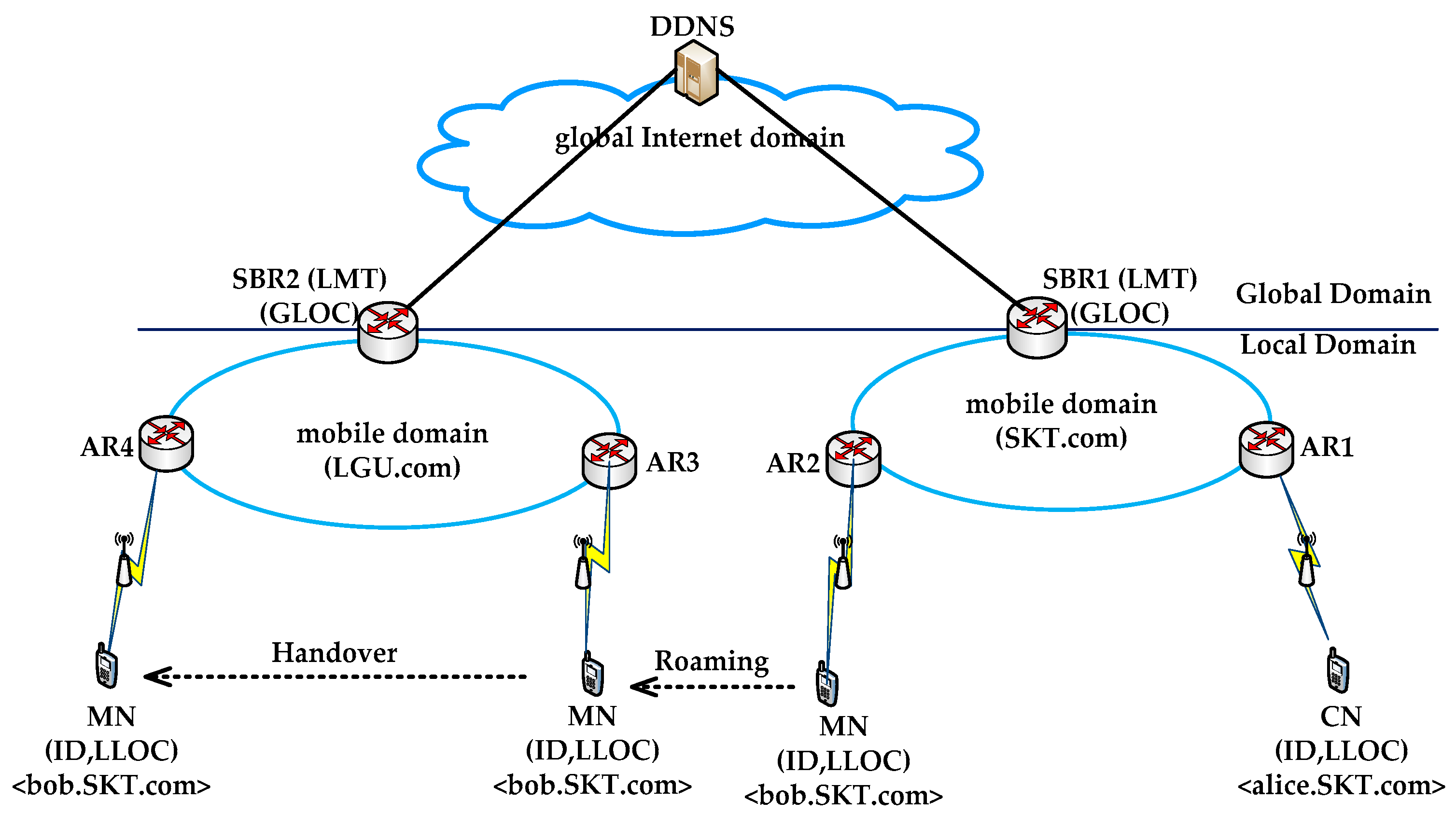
3. Proposed Scheme
3.1. Overview
3.2. Procedures for Non-Roaming Scenario
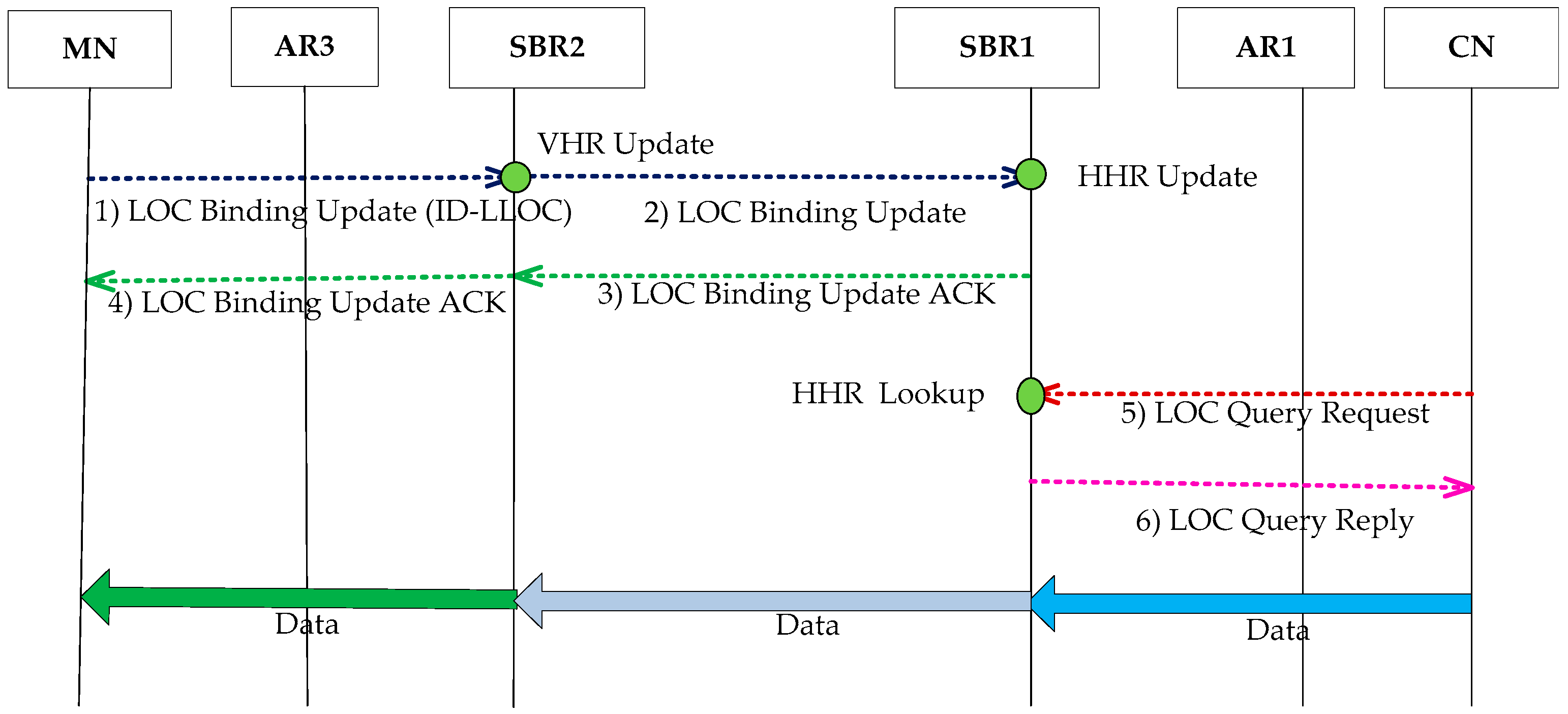
3.3. Procedures for Roaming Scenario
3.4. Procedures for the Handover Scenario
4. Performance Analysis
4.1. Analysis Model
4.2. Analysis of Control Traffic Overhead
4.2.1. ILNP-Global
4.2.2. ILNP-Local
4.2.3. ILNP-Distributed
4.3. Analysis of Total Transmission Delay
4.3.1. ILNP-Global
4.3.2. ILNP-Local
4.3.3. ILNP-Distributed
4.4. Analysis of Handover Delay
4.4.1. ILNP-Global
4.4.2. ILNP-Local
4.4.3. ILNP-Distributed
5. Numerical Results
5.1. Non-Roaming Case
5.1.1. Control Traffic Overhead (CTO)
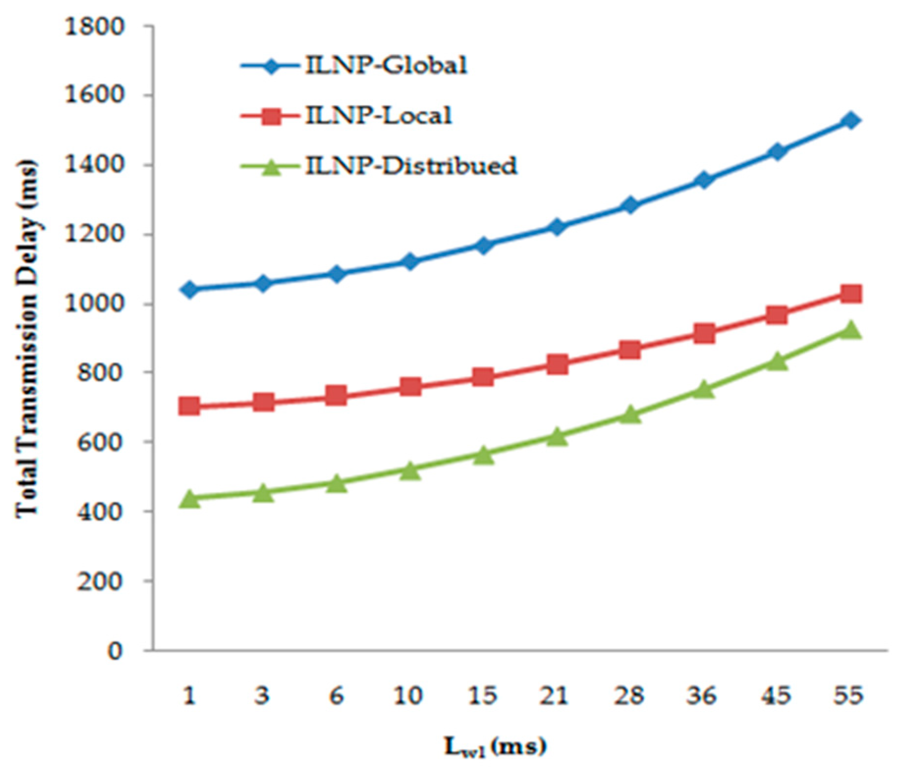
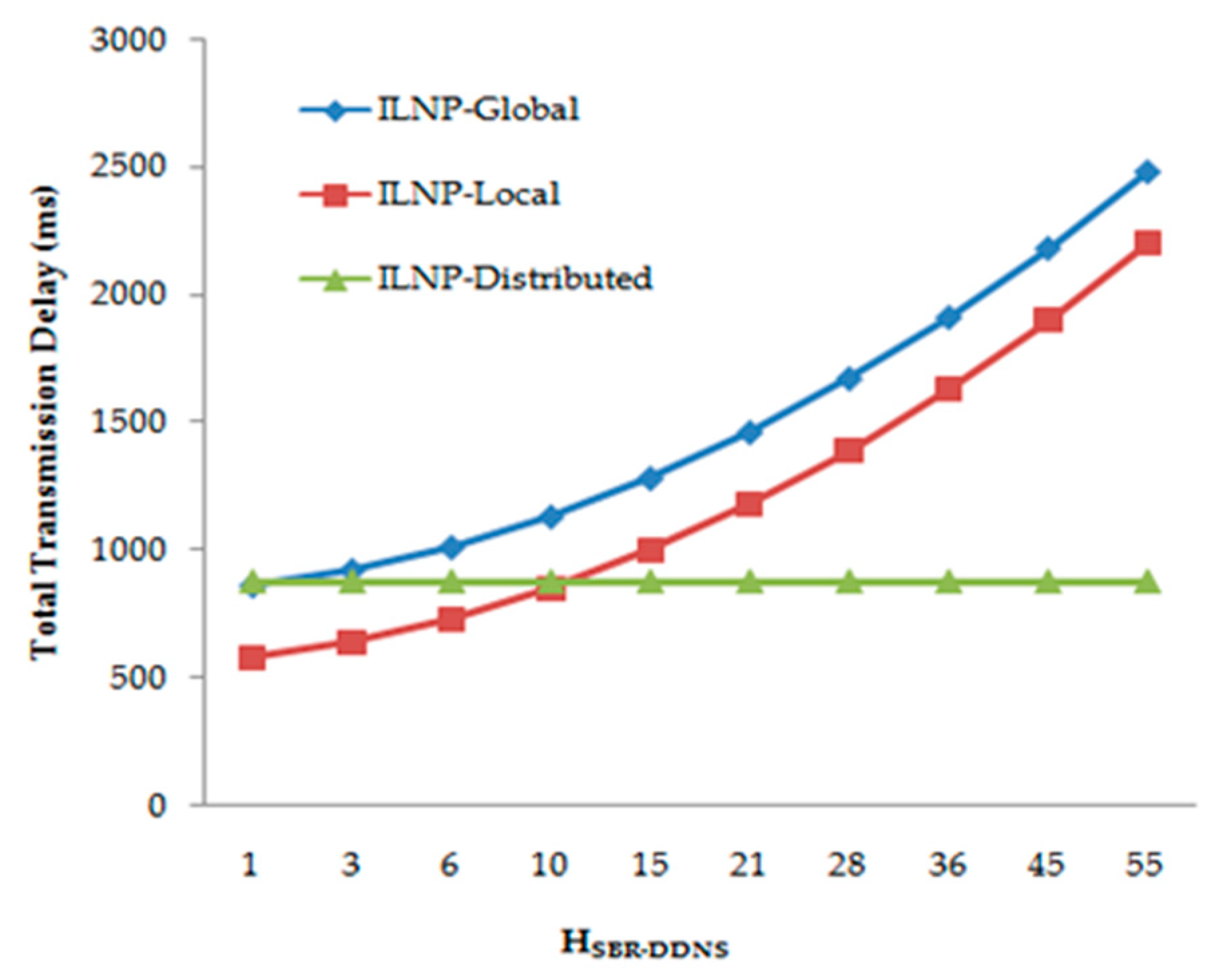
5.1.2. Total Transmission Delay (TTD)
5.2. Roaming Case
5.2.1. Control Traffic Overhead (CTO)
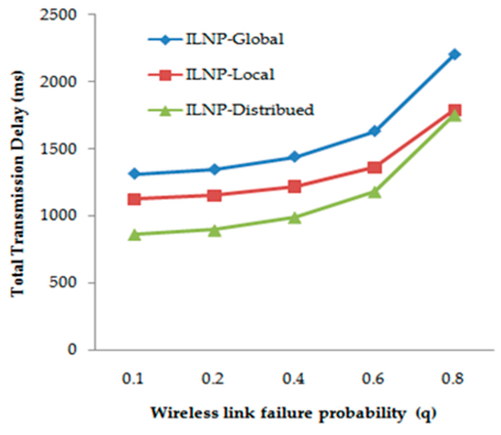
5.2.2. Total Transmission Delay (TTD)
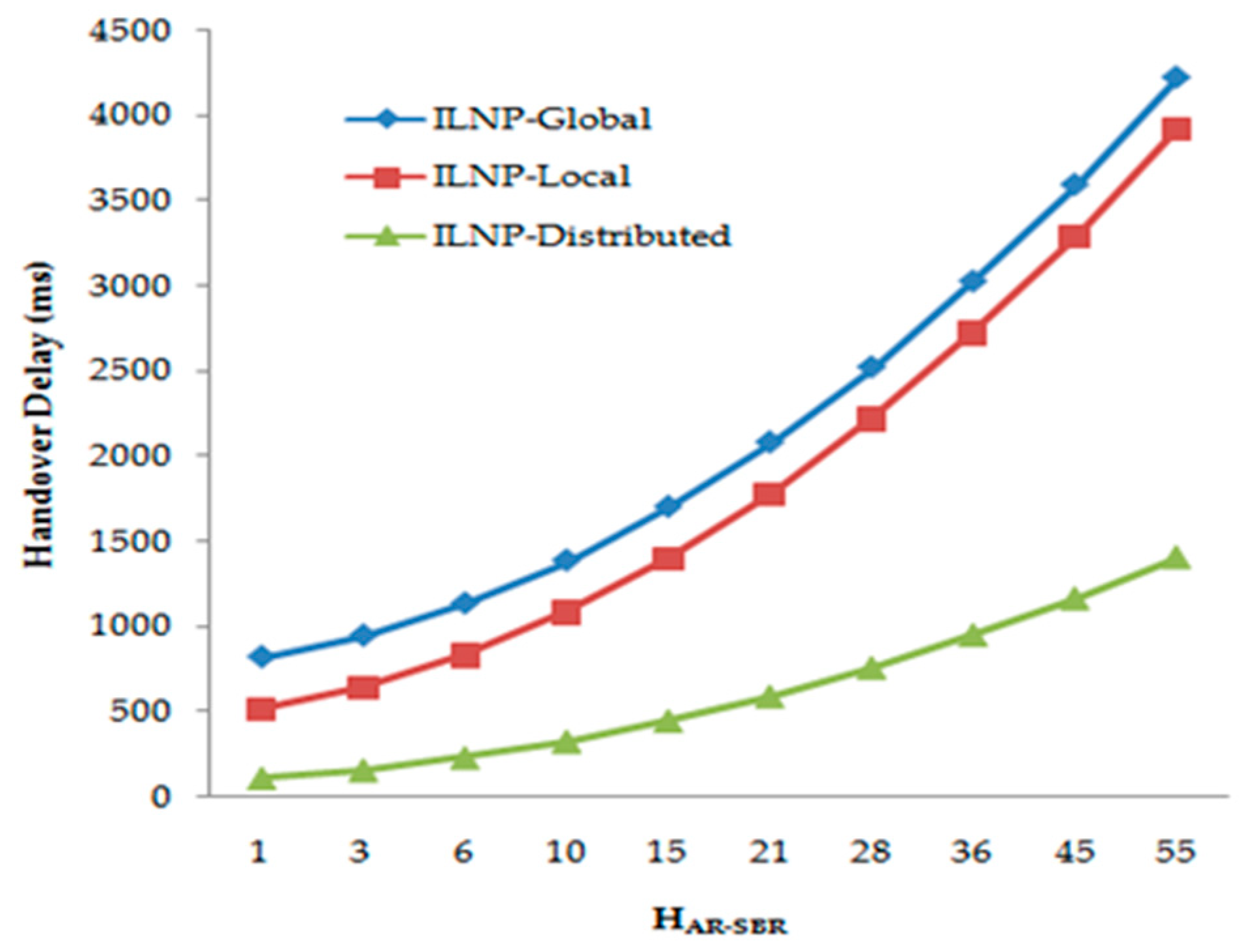
5.3. Handover Delay (HOD)
5.4. Implementation Perspective
6. Conclusions
Author Contributions
Funding
Conflicts of Interest
List of Acronyms
| Acronym | Description |
| ILNP | Identifier Locator Network Protocol |
| DDNS | Dynamic Domain Name Service |
| ID-LOCs | Identifier-locators |
| m-DDNS | mobile DDNS m-DDNS |
| HHR | Home Host Register |
| VHR | Visiting Host Register |
| IETF | Internet Engineering Task Force |
| SBR | Site Border Router |
| LLOC | Local Locator |
| GLOC | Global Locator |
| AR | Access Router |
| LMT | Local Mapping Table |
| LD | Link Detected |
| CTO | Control. Traffic Overhead |
| TTD | Total Transmission Delay |
| BUD | binding update Delay |
| BQD | Binding Query Delay |
| DDD | Data Delivery Delay |
| HOD | Handover Delay |
References
- Gohar, M.; Jung, H.; Koh, S.J. Distributed Mapping Management of Identifiers and Locators in Mobile-Oriented Internet Environment. Int. J. Commun. Syst. 2014, 27, 95–115. [Google Scholar] [CrossRef]
- Morgan Stanley Report, Internet Trends. 2010. Available online: http://www.morganstanley.com/ (accessed on 28 September 2019).
- Meyer, D.L.; Zhang, K. Fall, Report from the IAB Workshop on Routing and Addressing; IET: Fremont, CA, USA, 2007; RFC 4984. [Google Scholar]
- Atkinson, R.J.; Bhatti, S.N.; Andrews, S.T. Identifier-Locator Network Protocol (ILNP) Architecture Description; IETF: Fremont, CA, USA, 2012; RFC 6740. [Google Scholar]
- Atkinson, R.J.; Bhatti, S.N.; Andrews, S.T. Optional Advances Deployment Scenarios for the Identifier-Locator Network Protocol (ILNP); IETF: Fremont, CA, USA, 2012; RFC 6748. [Google Scholar]
- Atkinson, R.J.; Bhatti, S.N.; Andrews, S.T.; Rose, S. DNS Resource Records for the Identifier-Locator Network Protocol (ILNP); IETF: Fremont, CA, USA, 2012; RFC 6742. [Google Scholar]
- Atkinson, R.J.; Bhatti, S.N.; Stephen, H. ILNP: Mobility, multi-homing, localised addressing and security through naming. Telecommun. Syst. 2009, 42, 273–291. [Google Scholar] [CrossRef]
- Atkinson, R.J. An Introduction to the Identifier-Locator Network Protocol (ILNP). In Proceedings of the IEEE London Communications Symposium (LCS), London, UK, 14–15 September 2006. [Google Scholar]
- Atkinson, R.J.; Bhatti, S.N.; Stephen, H. Mobility as an Integrated Service Through the Use of Naming. In Proceedings of the 2nd ACM International Workshop on Mobility in the Evolving Internet (MobiArch), Kyoto, Japan, 27–30 August 2007. [Google Scholar]
- Atkinson, R.J.; Bhatti, S.N.; Stephen, H. A Proposal for Unifying Mobility with Multi-Homing, NAT, & Security. In Proceedings of the 5th ACM International Workshop on Mobility Management and Wireless Access (MobiWAC), Chania, Crete, 22 October 2007. [Google Scholar]
- Atkinson, R.J.; Bhatti, S.N.; Stephen, H. Mobility Through Naming: Impact on DNS. In Proceedings of the 3rd ACM International Workshop on Mobility in the Evolving Internet (MobiArch), Seatlle, WA, USA, 22 August 2008. [Google Scholar]
- Atkinson, R.J.; Bhatti, S.N.; Stephen, H. Harmonized Resilience, Security and Mobility Capability for IP. In Proceedings of the 28th IEEE Military Communications Conference (MILCOM), Boston, MA, USA, 18–21 October 2009. [Google Scholar]
- Rehunathan, D.; Atkinson, R.J.; Bhatti, S.N. Enabling Mobile Networks Through Secure Naming. In Proceedings of the 27th IEEE Military Communications Conference (MILCOM), San Diego, CA, USA, 16–19 November 2008. [Google Scholar]
- Makaya, C.; Pierre, S. An analytical framework for performance evaluation of IPv6-based mobility management protocols. IEEE Trans. Wirel. Commun. 2008, 7, 972–983. [Google Scholar] [CrossRef]
- Choi, N.J.; Gohar, M.; Koh, S.J. Domain-based distributed identifier-locator mapping management in Internet-of-Things networks. Int. J. Netw. Manag. 2018, 28, e2035. [Google Scholar] [CrossRef]
- Kim, J.I.; Jung, H.; Koh, S.J. Mobile-Oriented Future Internet: Implementation and Experimentations over EU-Korea Testbed. Electronics 2019, 8, 338. [Google Scholar] [CrossRef]
- Gohar, M.; Ahmed, W.; Bashir, F.; Choi, J.G.; Koh, S.J. A hash-based distributed mapping control scheme in mobile locator-identifier separation protocol networks. Int. J. Netw. Manag. 2017, 27, e1961. [Google Scholar] [CrossRef]
- Atkinson, R.J.; Bhatti, S.N.; Stephen, H. Evolving the Internet Architecture Through Naming. IEEE J. Sel. Areas Commun. 2010, 28, 1319–1325. [Google Scholar] [CrossRef]
- IEEE 802.21. Local and Metropolitan Area Networks: Media Independent Handover (MIH); IEEE: Piscataway, NJ, USA, 2006. [Google Scholar]
- Jung, H.; Gohar, M.; Kim, J.I.; Koh, S.J. Distributed mobility control in proxy mobile IPv6 networks. IEICE Trans. Commun. 2011, 94, 2216–2224. [Google Scholar] [CrossRef]
- Gohar, M.; Koh, S.J. A distributed mobility control scheme in LISP network. Wirel. Netw. 2014, 20, 245–259. [Google Scholar] [CrossRef]


| No. | Host Name | ID | LOC | Status |
|---|---|---|---|---|
| 1 | alice.SKT.com | ID1 | LLOC | Home |
| 2 | bob.SKT.com | ID2 | GLOC | Roaming |
| 3 | ∙∙∙ | ∙∙∙ | ∙∙∙ | ∙∙∙ |
| No. | Host Name | ID | LOC | Home Domain |
|---|---|---|---|---|
| 1 | bob.SKT.com | ID2 | LLOC | GLOC |
| 2 | ∙∙∙ | ∙∙∙ | ∙∙∙ | ∙∙∙ |
| 3 | ∙∙∙ | ∙∙∙ | ∙∙∙ | ∙∙∙ |
| Schemes | LOC | Mapping Architecture | Mobility Agent |
|---|---|---|---|
| ILNP-Global | GLOC | Centralized | DDNS |
| ILNP-Local | LLOC, GLOC | Centralized | SBR (LMT), DDNS |
| ILNP-Distributed | LLOC, GLOC | Distributed | SBR (m-DDNS) |
| Parameters | Description |
|---|---|
| Sc | Size of control packets (bytes) |
| Sd | Size of data packets (bytes) |
| Bw | Bandwidth of a wired link (Mbps) |
| Bwl | Bandwidth of a wireless link (Mbps) |
| Lw | Latency of a wired link (ms) |
| Lwl | Latency of a wireless link (ms) |
| Hx-y | Hop count between nodes x and y |
| α [17] | Unit cost for binding update |
| β [17] | Unit cost for database search |
| NHost/AR | Number of hosts attached to an AR |
| NAR | Number of ARs in the domain |
| NSBR | Number of SBRs |
| q | Wireless link failure probability |
| Tq [15,16,17,19,20,21] | Average queuing delay at each router |
© 2019 by the authors. Licensee MDPI, Basel, Switzerland. This article is an open access article distributed under the terms and conditions of the Creative Commons Attribution (CC BY) license (http://creativecommons.org/licenses/by/4.0/).
Share and Cite
Gohar, M.; Choi, J.-G.; Ahmed, W.; Rahman, A.U.; Muzammal, M.; Koh, S.-J. Distributed Identifier-Locator Mapping Management in Mobile ILNP Networks. Electronics 2020, 9, 58. https://doi.org/10.3390/electronics9010058
Gohar M, Choi J-G, Ahmed W, Rahman AU, Muzammal M, Koh S-J. Distributed Identifier-Locator Mapping Management in Mobile ILNP Networks. Electronics. 2020; 9(1):58. https://doi.org/10.3390/electronics9010058
Chicago/Turabian StyleGohar, Moneeb, Jin-Ghoo Choi, Waleed Ahmed, Arif Ur Rahman, Muhammad Muzammal, and Seok-Joo Koh. 2020. "Distributed Identifier-Locator Mapping Management in Mobile ILNP Networks" Electronics 9, no. 1: 58. https://doi.org/10.3390/electronics9010058
APA StyleGohar, M., Choi, J.-G., Ahmed, W., Rahman, A. U., Muzammal, M., & Koh, S.-J. (2020). Distributed Identifier-Locator Mapping Management in Mobile ILNP Networks. Electronics, 9(1), 58. https://doi.org/10.3390/electronics9010058