Article

Self-Powered Operational Amplifying System with a Bipolar Voltage Generator Using a Piezoelectric Energy Harvester

1
Department of Electrical Engineering, Hanyang University, Wangsimni-ro, Seongdong-gu, Seoul 133–791, Korea
2
Department of Mechatronics Engineering, College of EME, National University of Sciences and Technology (NUST), Islamabad 44000, Pakistan
3
Korea Electric Power Research Institute, Daejeon 34056, Korea
*
Author to whom correspondence should be addressed.
These authors contributed equally to this work.
Electronics 2020, 9(1), 41; https://doi.org/10.3390/electronics9010041
Submission received: 20 November 2019 / Revised: 23 December 2019 / Accepted: 25 December 2019 / Published: 27 December 2019
(This article belongs to the Special Issue Energy Harvesting and Storage Applications)

Abstract

:
Piezoelectric devices previously studied usually generated a single voltage to power an electronic device. However, depending on the user’s purpose, the electronic device may need dual power supply. Here, we report a self-powered bipolar voltage generator using a piezoelectric energy harvester with two piezoelectric devices. When a force is applied to the piezoelectric energy harvester, the two piezoelectric devices separately supply positive and negative voltages to the operational amplifier that requires dual power supply to amplify an AC signal that have positive and negative polarity. At the same time, the harvester supplies additional power to an electronic device through a DC-to-DC converter with an output voltage of 3.3 V. This technique proves the feasibility of applying the piezoelectric energy harvester to operational amplifying systems in the field of sound, earthquake, and sonar that require both bipolar and single voltages without external power sources.

1. Introduction

Most electronic devices need electrical energy to operate. When a battery is discharged, it must be recharged or replaced. As recharging and replacing are inconvenient, energy harvesting technologies have been developed to use renewable electricity from wasted energy. The technology used to supply power to electronic devices by energy harvesting is an integral part of modern society.
The main advantage of energy harvesting using piezoelectric materials is suitable to capture small scale vibrations. In addition, this harvesting method is unaffected by nature. Various methods have been researched to obtain renewable electrical energy from environmental energy wasted [1,2,3,4,5]. Among them, the most well-known method involves solar power, which generate electrical energy from sunlight [6,7]. However, those methods have a disadvantage in that they depend on the natural environment, such as the weather. Therefore, instead of energy harvesting from nature, many other energy harvesting technologies are have been studied, including energy harvesters that use piezoelectric materials [8,9,10,11]. Piezoelectric materials are able to convert mechanical energy to electrical energy. Among piezoelectric materials, lead zirconate titanate (PZT) has been widely used as an energy harvester to generate electricity from wasted vibration and kinetic energy for the operation of electronic devices with or without batteries [12,13,14,15].
Most studies on piezoelectric energy harvesting have been performed with single layer [16,17,18,19] or multi-layer piezoelectric device [20] to produce a single voltage for power supply. However, depending on the purpose of the user, it is necessary to apply a dual power supply to an electronic device. The operational amplifier (op-amp), which is used to amplify an input signal generated from real environments (sound, earthquake, sonar), is an example (Figure 1). To amplify a small signal using an op-amp, Dual power supply is needed because the output voltage cannot be larger than the voltage supplied to the op-amp.
A voltage divider is also used to make voltages with dual-polarity from one voltage source. However, the use of voltage divider causes power loss and the use of additional components increases the circuit size. Instead of using an additional voltage divider, we used two piezoelectric devices as a single harvester and used it as independent power sources. It can provide higher power generation than when using one piezoelectric device.
Herein, we propose a self-powered operational amplifying system with a bipolar voltage generator using a piezoelectric energy harvester. The piezoelectric energy harvester (PEH) was fabricated with two independent PZTs and used to apply dual power supply for operation of an op-amp to amplify a small signal that have positive and negative polarity. Additionally, single voltage can be used to supply power for a DC-to-DC converter and a final load device. This self-power generator supplies power for electronic devices using the PEH without external power sources.

2. Method

2.1. Energy Harvester Design

A piezoelectric device consisting of a substrate, SUS304, and PZT ceramic can convert mechanical energy to electrical energy when external pressure is applied to the PZT [21,22,23]. Figure 2a illustrates the piezoelectric device with dimensions of 60 × 40 mm2, a substrate thickness of 0.1 mm, and a 0.2-mm-thick ceramic. Other material properties are shown in Table 1. One of the sides has holes to fix the piezoelectric device to the structure with screws. In order for each piezoelectric device to generate independent voltage without electrical influence on each other, insulating layers added to each piezoelectric device. A double-sided adhesive tape was used between the two piezoelectric devices to form the PEH as shown in Figure 2b. The purpose of the PEH is to supply power to electronic devices that need dual power supply for operation. To clarify the superiority of our design, we conducted the linear static analysis to compare with a single layer harvester which has the same thickness of PZT ceramic using ANSYS v17.2 (type of element: SOLID186 with 20 nodes) as shown in Figure S1 (See Supplementary Materials). In result, our design showed a higher electrical output of 0.47 mJ than the single layer type harvester of 0.32 mJ because of the farther distance between the PZT layer and a neutral axis.

2.2. Simulation of Piezoelectric Devices

Van Dyke’s model is a representative of piezoelectric equivalent circuit model, and is shown in Figure 3a [24]. The PZT can be described as an equivalent circuit consisting of a resistor, an inductor, and capacitors. Each parameter of the elements can be obtained using an impedance analyzer (E4990A, KEYSIGHT, USA), which sends a frequency sweep signal to the sample. One end of the PEH was fixed to a support structure then mounted to a vibration exciter as a cantilever [25,26]. The values of L1, C1, R1, and C0 of PZT1 and PZT2 were determined; schematics of the PZTs are shown in Figure 3b,c.
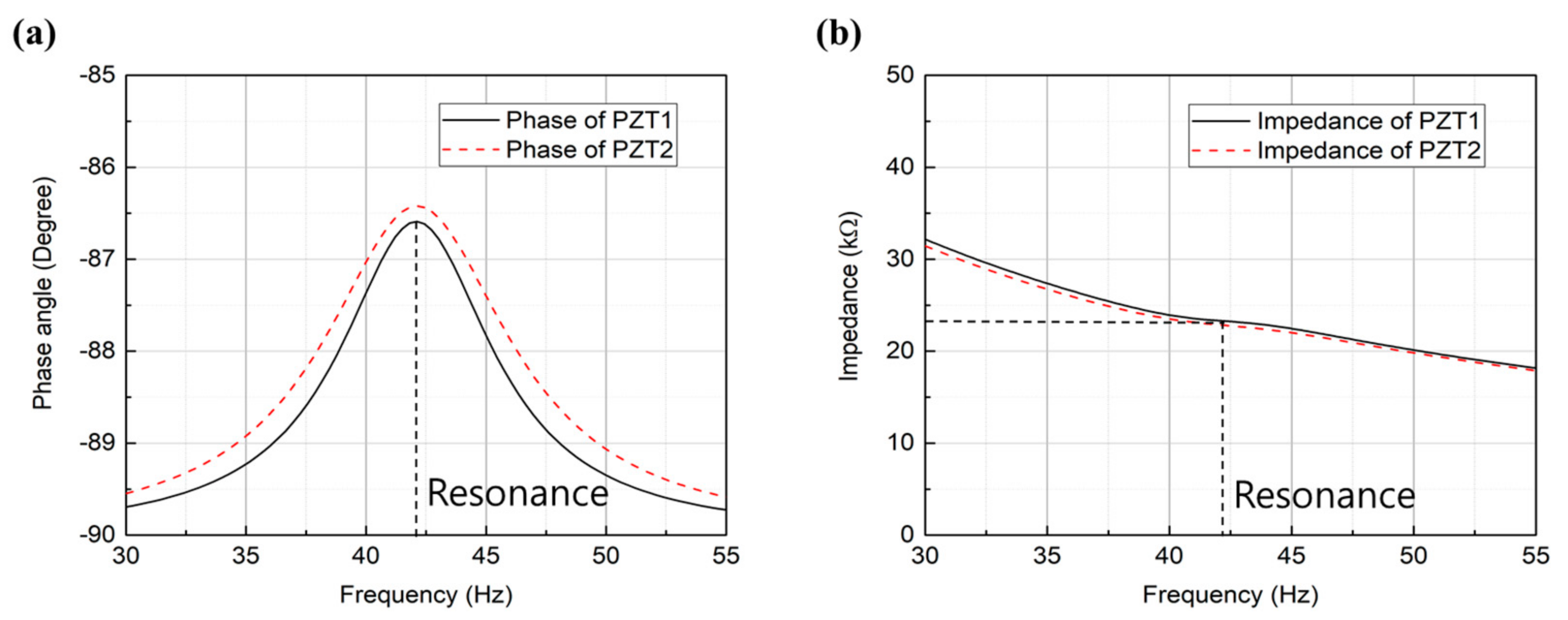
To determine the power generation characteristics of the piezoelectric devices, the impedance matching point [27] and PEH resonance frequency are considered [28]. Although both of them can be obtained experimentally, such an approach can be time consuming. We estimated the resonance frequency and impedance matching point with equivalent circuit simulation. The phase and impedance characteristics (Figure 4a,b) of the piezoelectric devices were obtained using the LTspice simulation tool in the range of 30-55 Hz using the parameters shown in Table 2.
PZT was dominated by the internal capacitor at the low frequency, whose phase was close to −90° at non-resonance frequencies, and increased at the resonance frequency. The simulation results confirmed that 42 Hz is the resonance frequency and impedance is 23 kΩ at 42 Hz.

2.3. Experimental Analysis

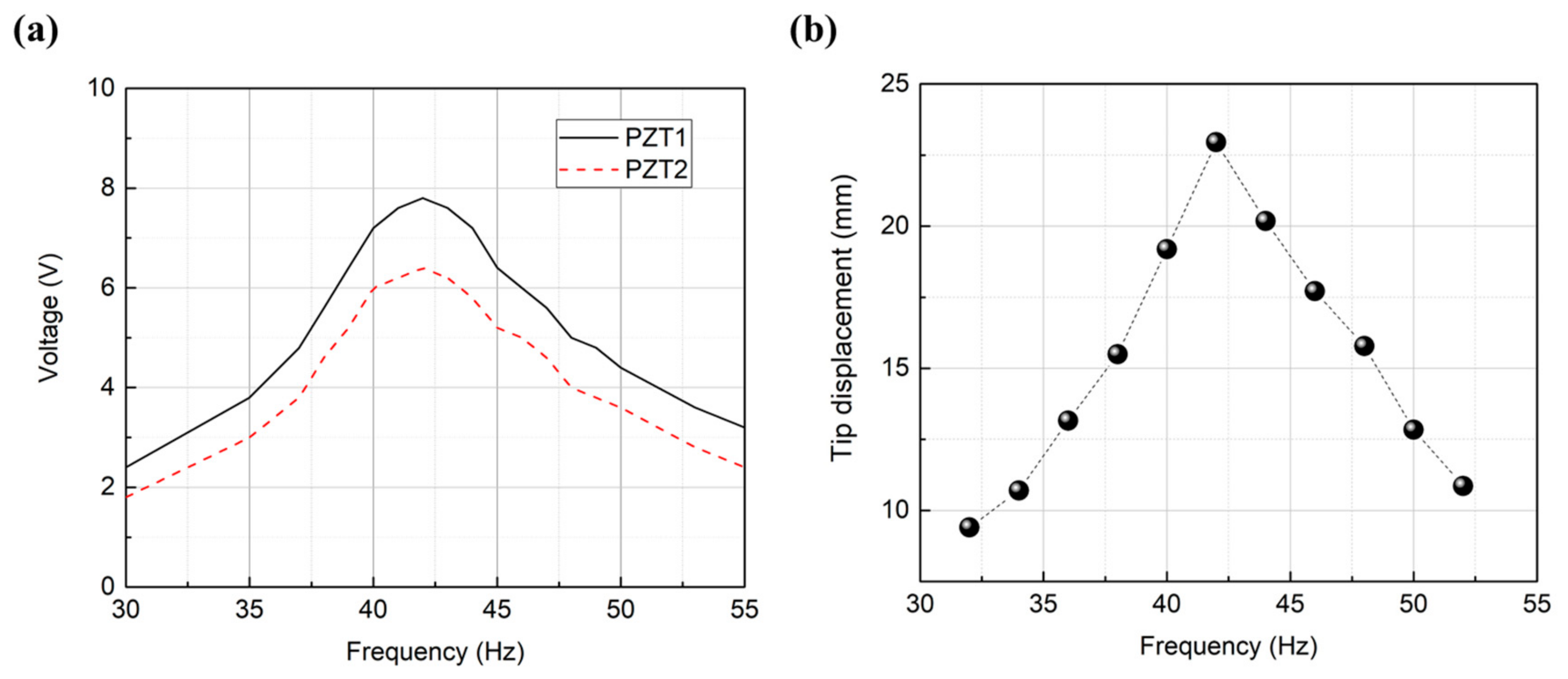
For reliability, the resonance frequencies of the PEH, which combined PZT1 and PZT2, were experimentally obtained with a vibration exciter. As confirmed by the simulation results in Figure 4a, the voltage generated (Figure 5a) and the tip displacement of the PEH (Figure 5b) is also maximized at the resonance frequency (42 Hz).

3. Results and Discussion

To receive the electrical energy from the PZTs, a standard interface circuit as shown in Figure 6a is needed. The values of the current sources of PZT1 and PZT2 were obtained by measuring the voltages of the PZTs at a resonance frequency of 42 Hz with a vibration exciter. Positive and negative cycles exist in the PEH with a sine waveform obtained by the vibration exciter. To use the power from the PEH for electronic devices, the waveform needed to be rectified. Each rectified waveform from the PZTs is respectively stored in two capacitors: Crect1 and Crect2. The negative polarity of Vrect1 and the positive polarity of Vrect2 were connected in series. Finally, positive and negative sources were obtained from the node A for devices that require bipolar voltage for operation, such as an op-amp. Figure 6b shows the experimental setup, including a digital oscilloscope (DPO 4054B, Tektronix, USA), a waveform generator (33500B Series, Keysight Technologies, USA), a power amplifier (Type 2718, Brüel & Kjaer, Denmark), a vibration exciter (Type 4809, Brüel & Kjaer, Denmark) with the PEH, and a circuit board with a standard interface circuit. The PEH was attached to the structure and fixed at the vibration exciter. The sinusoidal wave was amplified at the power amplifier to drive the vibration exciter. The output power generated from the PEH was connected to the circuit board, which had rectifiers. The voltages of the PEH were measured using the oscilloscope. Figure 6c shows the sine waveforms generated from PZT1 and PZT2 without load at a resonance frequency of 42 Hz using the vibration exciter. The peak voltages of PZT1 and PZT2 were 8 and 6.2 V, respectively. The voltage rectified with two rectifiers at the resistive matching point of 23 kΩ for each PZT had one polarity, as shown in Figure 6d. Since the input voltage to the interface circuit is 8 V at 23 kΩ, the input power is 2.78 mW, and the output voltage of the interface circuit is 5.9 V, so the output power is 1.51 mW as calculated using Equation (1). Therefore, the efficiency of the interface circuit is 54% and the power consumption is 1.27 mW.
P = V 2 R
Crect1 and Crect2 were connected in series and the bipolar voltage was obtained from the node A, as shown in Figure 6e. The voltages from the two PZTs individually charged at Crect1 and Crect2 are shown in Figure 6f. This energy which is divided into each polarity can be used for electronic devices that need dual power supply.
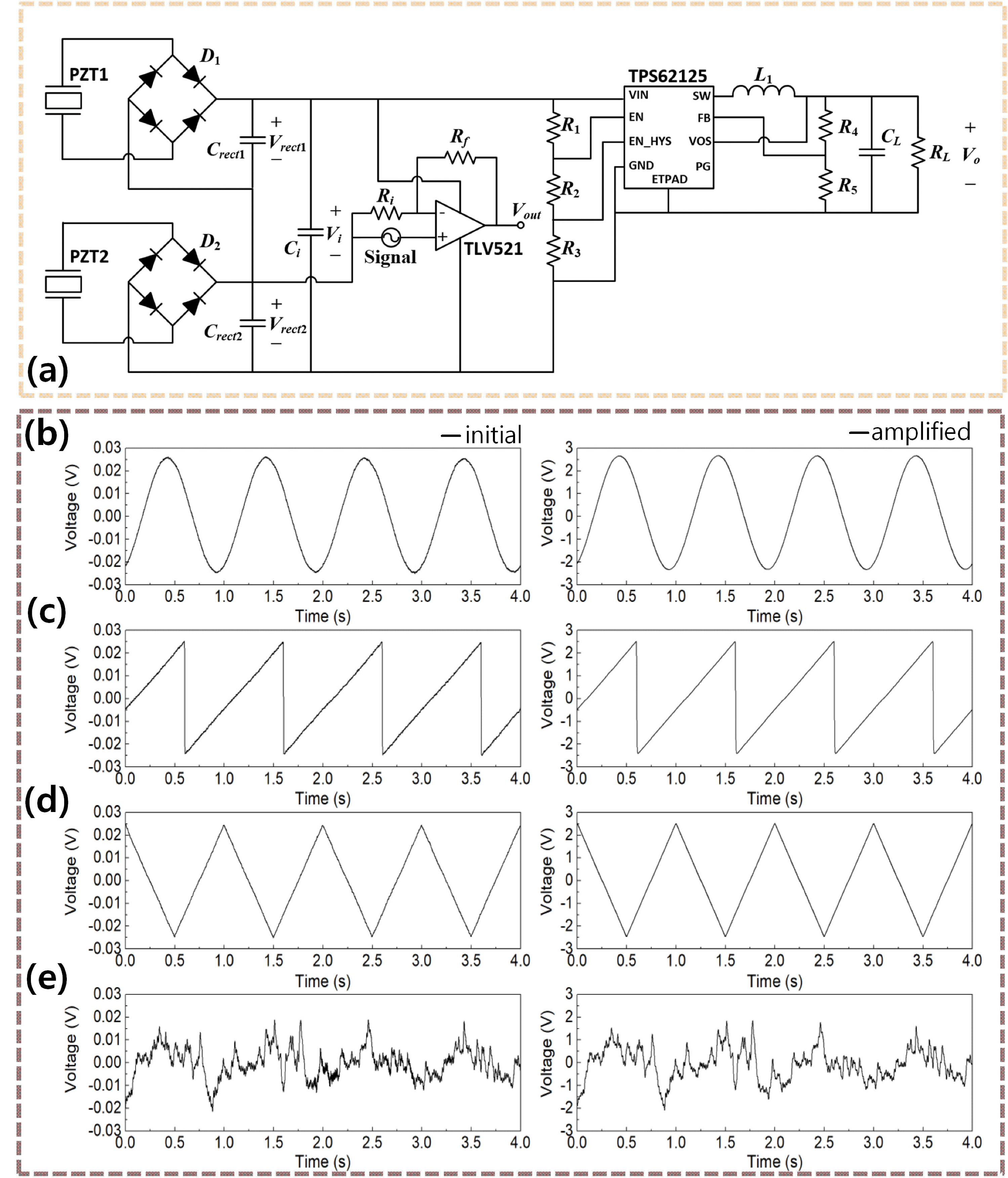
The op-amp is usually used for amplification of the input signal when an input signal from sound, earthquake, or sonar is too small to use. As the output amplitude of the op-amp cannot be larger than the supplied amplitude of the voltage to the op-amp, a higher voltage needs to be applied to produce the appropriate amplitude. In such a case, only a positive voltage is supplied to the amplifier; the output voltage cannot be negative. In order to amplify the input signal with positive and negative voltages, bipolar voltage needs to be supplied to the two power terminals of the op-amp. Figure 7a shows the entire circuit system of the self-powered operational amplifying system, in which the energy generated from the PZTs is rectified by D1 and D2 to be stored in Crect1 and Crect2 as the shape generated from the PZTs is sinusoidal.
A non-inverting amplifier was obtained with the operational op-amp; the output gain is:
Vout/Vin = Rf/Ri + 1
Ri and Rf were 10 kΩ and 1 MΩ, respectively, yielding an output 101 times higher than the input. By changing Rf, the gain can be easily adjusted according to the user’s requirement. The waveform generator was used to supply an input voltage of 50 mV (peak-to-peak) assuming an environment where a minor signal occurs. As the gain was 101, the output voltage was approximately 5 V (peak-to-peak). The resistors have an error of 5%, and thus the output voltage may also have an error of 5%. However, if a resistor with a low error is used, a more accurate result can be obtained. The parameters used in the circuit system are shown in Table 3. Four types of waveforms, (b) sine, (c) saw-tooth, (d) triangle, and (e) random assuming real environments (sound, earthquake, sonar etc.) were supplied to the (+) input of the amplifier using the waveform generator. The amplified output signal exactly amplified the shape of the input signal, as shown in Figure 7b–e. The results confirmed that the PEH can operate the op-amp using both positive and negative voltages.
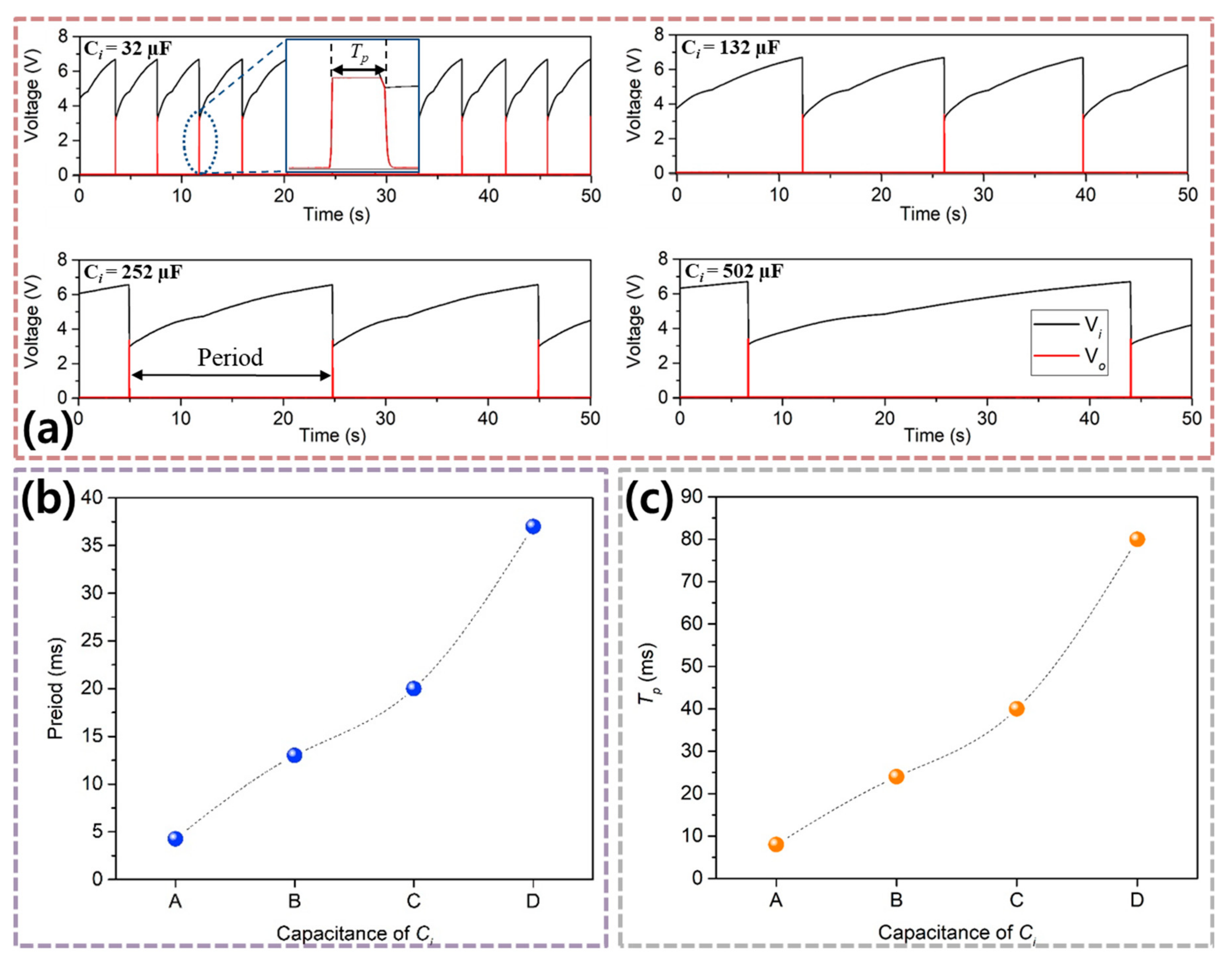
DC-to-DC converter with a UVLO function (TPS62125, Texas Instruments, USA) was used in this system to supply a single voltage to a load. The ULVO indicates an under voltage lockout function of a circuit, which generates a constant voltage as output when the input voltage is larger than the specific rising threshold voltage set by adjusting the values of the input resistors; the circuit is turned off when the input voltage is smaller than the falling threshold level as a hysteresis. Therefore, when power is not supplied to the device, it is possible to operate the device by storing sufficient energy in the input capacitors. We set the rising threshold voltage to 6.7 V, the falling threshold voltage to 3 V, and the output voltage to 3.3 V, which is the rated voltage of a wireless sensor (eZ430-RF2500, Texas Instruments, USA), which consists of a TI MSP430 series MCU and a CC2500 (RF transceiver). The turn-on and turn-off states of the DC-to-DC converter are determined by the voltage level of the capacitor, Ci. According to the capacitance of Ci, the time and period of the power transmission for RL are adjusted. When the capacitance of the capacitor increases, more energy is stored and the power transmission time period to RL increases. Conversely, when the capacitance of the capacitor is small, less energy is stored in the capacitor, so that the power transmission time period is reduced and the device can be operated more frequently. Therefore, a user can set the value of Ci according to the requirements of the electronic application, such as a wireless sensor. In this study, a 100-Ω resistor was connected at the output of the converter because devices such as those for wireless communication have an input resistance of 100 Ω. Any electronic device or additional circuit system that needs a single voltage source can be a load. We confirmed the trends of time and period by changing the value of Ci; four capacitors with different capacities were used, as shown in Table 4. Vi increased from 3 to 6.7 V; when Vi reached the rising threshold voltage of 6.7 V, the circuit turned on, whose output is denoted as Vo. Graphs of Vi and Vo along the capacitances of the capacitor are shown in Figure 8a. The exact period and power transmission time (Tp) of the circuit are shown in Figure 8b,c, respectively.

4. Conclusions

We designed and manufactured a self-powered operational amplifying system with a bipolar voltage generator using a piezoelectric energy harvester (PEH) for applying to various real fields (sound, earthquake, and sonar). The PEH consisted of two piezoelectric devices with an insulating layer to prevent energy loss. A standard interface circuit was designed and tested to output bipolar voltages for self-operating an operational amplifier using two capacitors which were connected in series. Furthermore, we verified that the PEH can simultaneously supply additional power to an electronic device as a load through a DC-to-DC converter with an output voltage of 3.3 V which is the rated voltage of a wireless sensor. In conclusion, this technique proves the potential and the feasibility of applying the piezoelectric energy harvester to operational amplifying systems, which is essentially used for amplifying small signals in various fields as well as self-powered electronic devices.

Supplementary Materials

The following are available online at https://www.mdpi.com/2079-9292/9/1/41/s1, Figure S1: Linear static analysis (a) Single layer type piezoelectric energy harvester (b) Suggested piezoelectric energy harvester.

Author Contributions

Conceptualization, S.Y.J.; Investigation, J.Y.C. and S.D.H.; Visualization, W.H.; Methodology, H.J.; Resources, J.H.A. and J.P.J.; Writing-review & editing, T.H.S. All authors have read and agreed to the published version of the manuscript.

Funding

This research was funded by the Ministry of Science and ICT grant number 2017H1D8A2032495.

Acknowledgments

This research was supported by a Program for Fostering Next-generation Researchers in Engineering of the National Research Foundation of Korea (NRF).

Conflicts of Interest

The authors declare no conflict of interest.

References

  1. Yang, W.; Towfighian, S. Low frequency energy harvesting with a variable potential function under random vibration. Smart Mater. Struct. 2018, 27, 114004. [Google Scholar] [CrossRef]
  2. Liao, Y.; Liang, J. Maximum power, optimal load, and impedance analysis of piezoelectric vibration energy harvesters. Smart Mater. Struct. 2018, 27, 075053. [Google Scholar] [CrossRef]
  3. Woo, M.S.; Hong, S.K.; Jung, H.J.; Yang, C.H.; Song, D.; Sung, T.H. Study on the Strain Effect of a Piezoelectric Energy Harvesting Module. Ferroelectrics 2013, 449, 33–41. [Google Scholar] [CrossRef]
  4. Seung, W.; Gupta, M.K.; Lee, K.Y.; Shin, K.S.; Lee, J.H.; Kim, T.Y.; Kim, S.; Lin, J.; Kim, J.H.; Kim, S.W. Nanopatterned textile-based wearable triboelectric nanogenerator. ACS Nano 2015, 9, 3501–3509. [Google Scholar] [CrossRef] [PubMed]
  5. Yi, F.; Lin, L.; Niu, S.; Yang, P.K.; Wang, Z.; Chen, J.; Zhou, Y.; Zi, Y.; Wang, J.; Liao, Q.; et al. Stretchable-rubber-based triboelectric nanogenerator and its application as self-powered body motion sensors. Adv. Funct. Mater. 2015, 25, 3688–3696. [Google Scholar] [CrossRef]
  6. Brogan, Q.; O’Connor, T.; Ha, D.S. Solar and thermal energy harvesting with a wearable jacket. In Proceedings of the 2014 IEEE International Symposium on Circuits and Systems (ISCAS), Melbourne, Australia, 1–5 June 2014; pp. 1412–1415. [Google Scholar]
  7. Wang, C.; Li, J.; Yang, Y.; Ye, F. Combining Solar Energy Harvesting with Wireless Charging for Hybrid Wireless Sensor Networks. IEEE Trans. Mob. Comput. 2018, 17, 560–576. [Google Scholar] [CrossRef]
  8. Jeong, S.Y.; Hwang, W.S.; Cho, J.Y.; Jeong, J.C.; Ahn, J.H.; Kim, K.B.; Do Hong, S.; Song, G.J.; Jeon, D.H.; Sung, T.H. Piezoelectric device operating as sensor and harvester to drive switching circuit in LED shoes. Energy 2019, 177, 87–93. [Google Scholar] [CrossRef]
  9. Zhang, H.; Corr, L.R.; Ma, T. Effects of electrical loads containing non-resistive components on piezoelectric energy harvesting. Mech. Syst. Signal Process. 2018, 111, 210–221. [Google Scholar] [CrossRef]
  10. Ko, E.J.; Jeon, S.J.; Han, Y.W.; Jeong, S.Y.; Kang, C.Y.; Sung, T.H.; Seong, K.W.; Moon, D.K. Synthesis and characterization of nanofiber-type hydrophobic organic materials as electrodes for improved performance of PVDF-based piezoelectric nanogenerators. Nano Energy 2019, 58, 11–22. [Google Scholar] [CrossRef]
  11. Kim, M.O.; Pyo, S.; Oh, Y.; Kang, Y.; Cho, K.H.; Choi, J.; Kim, J. Flexible and multi-directional piezoelectric energy harvester for self-powered human motion sensor. Smart Mater. Struct. 2018, 27, 035001. [Google Scholar] [CrossRef]
  12. Jeong, S.Y.; Jung, H.J.; Jabbar, H.; Hong, S.K.; Ahn, J.H.; Sung, T.H. Design of a multi-array piezoelectric energy harvester for a wireless switch. Int. J. Hydrogen Energy 2016, 41, 12696–12703. [Google Scholar] [CrossRef]
  13. Cho, J.Y.; Choi, J.Y.; Jeong, S.W.; Ahn, J.H.; Hwang, W.S.; Yoo, H.H.; Sung, T.H. Design of hydro electromagnetic and piezoelectric energy harvesters for a smart water meter system. Sens. Actuators A Phys. 2017, 261, 261–267. [Google Scholar] [CrossRef]
  14. Jung, H.J.; Song, Y.; Hong, S.K.; Yang, C.H.; Hwang, S.J.; Jeong, S.Y.; Sung, T.H. Design and optimization of piezoelectric impact-based micro wind energy harvester for wireless sensor network. Sens. Actuators A Phys. 2015, 222, 314–321. [Google Scholar] [CrossRef]
  15. Jabbar, H.; Do Hong, S.; Hong, S.K.; Yang, C.H.; Jeong, S.Y.; Sung, T.H. Sustainable micro-power circuit for piezoelectric energy harvesting tile. Integr. Ferroelectr. 2017, 183, 193–209. [Google Scholar] [CrossRef]
  16. Chang, S.K.; Chen, K.W.; Yang, S.D.; Yang, C.L.; Cheng, K.W. An Autonomous Wireless Transmitter with Piezoelectric Energy Harvester from Short-Duration Vibrations. In Proceedings of the 2018 IEEE International Symposium on Circuits and Systems, Florence, Italy, 27–30 May 2018; pp. 1–4. [Google Scholar]
  17. Lee, M.; Yang, J.; Park, M.J.; Jung, S.Y.; Kim, J. Design and Analysis of Energy-Efficient Single-Pulse Piezoelectric Energy Harvester and Power Management IC for Battery-Free Wireless Remote Switch Applications. IEEE Trans. Circuits Syst. I Regul. Pap. 2018, 65, 366–379. [Google Scholar] [CrossRef]
  18. Kumar, A.; Kiran, R.; Kumar, S.; Chauhan, V.S.; Kumar, R.; Vaish, R. A Comparative Numerical Study on Piezoelectric Energy Harvester for Self-Powered Pacemaker Application. Glob. Chall. 2018, 2, 1700084. [Google Scholar] [CrossRef]
  19. Bouzelata, Y.; Kurt, E.; Uzun, Y.; Chenni, R. Mitigation of high harmonicity and design of a battery charger for a new piezoelectric wind energy harvester. Sens. Actuators A Phys. 2018, 273, 72–83. [Google Scholar] [CrossRef]
  20. Zhao, S.; Erturk, A. Deterministic and band-limited stochastic energy harvesting from uniaxial excitation of a multilayer piezoelectric stack. Sens. Actuators A Phys. 2014, 214, 58–65. [Google Scholar] [CrossRef]
  21. Hwang, S.J.; Jung, H.J.; Kim, J.H.; Ahn, J.H.; Song, D.; Song, Y.; Lee, H.L.; Moon, S.P.; Park, H.; Sung, T.H. Designing and manufacturing a piezoelectric tile for harvesting energy from footsteps. Curr. Appl. Phys. 2015, 15, 669–674. [Google Scholar] [CrossRef]
  22. Gatto, A.; Frontoni, E. Energy Harvesting system for smart shoes. In Proceedings of the 2014 IEEE/ASME 10th International Conference on Mechatronic and Embedded Systems and Applications, Senigallia, Italy, 10–12 September 2014; pp. 1–6. [Google Scholar]
  23. Yang, C.H.; Song, Y.; Woo, M.S.; Eom, J.H.; Song, G.J.; Kim, J.H.; Kim, J.; Lee, T.H.; Choi, J.Y.; Sung, T.H. Feasibility study of impact-based piezoelectric road energy harvester for wireless sensor networks in smart highways. Sens. Actuators A Phys. 2017, 261, 317–324. [Google Scholar] [CrossRef]
  24. Guan, M.; Liao, W.H. Studies on the circuit models of piezoelectric ceramics. In Proceedings of the International Conference on Information Acquisition, Hefei, China, 21–25 June 2004; pp. 26–31. [Google Scholar]
  25. Rakotondrabe, M.; Ivan, I.A.; Khadraoui, S.; Clevy, C.; Lutz, P.; Chaillet, N. Dynamic displacement self-sensing and robust control of cantilever piezoelectric actuators dedicated for microassembly. In Proceedings of the 2010 IEEE/ASME International Conference on Advanced Intelligent Mechatronics, Montreal, ON, Canada, 6–9 July 2010; pp. 557–562. [Google Scholar]
  26. Palosaari, J.; Leinonen, M.; Juuti, J.; Jantunen, H. The effects of substrate layer thickness on piezoelectric vibration energy harvesting with a bimorph type cantilever. Mech. Syst. Signal Process. 2018, 106, 114–118. [Google Scholar] [CrossRef] [Green Version]
  27. Fan, X.; Li, J.; Hao, H. Impedance resonant frequency sensitivity based structural damage identification with sparse regularization: Experimental studies. Smart Mater. Struct. 2019, 28, 015003. [Google Scholar] [CrossRef]
  28. Ahn, J.H.; Woo, M.S.; Song, D.; Hong, S.K.; Baek, K.H.; Hwang, S.J.; Sung, T.H. Establishment of the evaluation standard and the analysis technique for the tip mass method in piezoelectric energy-harvesting systems. J. Korean Phys. Soc. 2014, 65, 1943–1950. [Google Scholar] [CrossRef]
Figure 1. Conceptual design of a self-powered operational amplifying system with a bipolar voltage generator.
Electronics 09 00041 g001
Figure 2. Schematics of (a) the piezoelectric device and (b) the piezoelectric energy harvester.
Electronics 09 00041 g002
Figure 3. Equivalent circuit of the lead zirconate titanate (PZT): (a) Van Dyke’s model. Equivalent circuits of (b) PZT1 and (c) PZT2.
Electronics 09 00041 g003
Figure 4. Waveform characteristics of the PZTs: (a) phases, (b) impedances as a function of the frequency.
Electronics 09 00041 g004
Figure 5. (a) Voltage characteristics of the PZTs, (b) tip displacement of the piezoelectric energy harvester (PEH) as a function of the frequency.
Electronics 09 00041 g005
Figure 6. (a) Schematic of the standard interface circuit. (b) Experimental setup for testing the standard interface circuit. Waveforms of the PEH (c) Output voltages of PZT1 and PZT2. (d) Rectified voltages. (e) Bipolar voltages. (f) Charged voltages in the capacitors.
Electronics 09 00041 g006
Figure 7. (a) Entire circuit diagram of the self-powered operational amplifying system. Original and amplified signals: (b) Sine, (c) saw-tooth, (d) triangle, and (e) random assuming real environments (sound, earthquake, sonar etc.).
Electronics 09 00041 g007
Figure 8. (a) Power transmission time and period as a function of the capacitance Ci. (b) Period of the output voltage. (c) Power transmission time of the output voltage.
Electronics 09 00041 g008
Table 1. Material properties of the piezoelectric device.
MaterialParameterValue
Piezoelectric
ceramic
Density (g/cm3)7.6
eT33/e02300.0
d31 (10−12 mV)156.0
g31 (10−3 V·m/N)12.0
Kp (%)62.4
S11E (×10−12 m2/N)13.8
S11E (×10−12 m2/N)11.8
Steel substrateYoung’s modulus (GPa)193.0
Density (g/cm3)8.0
Table 2. Parameters of PZT1 and PZT2.
L1C1R1C0
PZT18.1 KH1.76 nF392.5 KΩ161.5 nF
PZT26.0 KH2.29 nF366.6 KΩ164.5 nF
Table 3. Parameters of the entire circuit system.
ParameterValueParameterValue
Crect147 µFCrect247 µF
Ri10 KΩRf10 MΩ
R12.5 MΩR2442 KΩ
R3808 KΩR41.8 MΩ
R5576 KΩRL100 Ω
L115 µHCL10 µF
Table 4. Capacitance values.
ABCD
32 µF132 µF252 µF502 µF