Compact Switched-Beam Array Antenna with a Butler Matrix and a Folded Ground Structure


Abstract
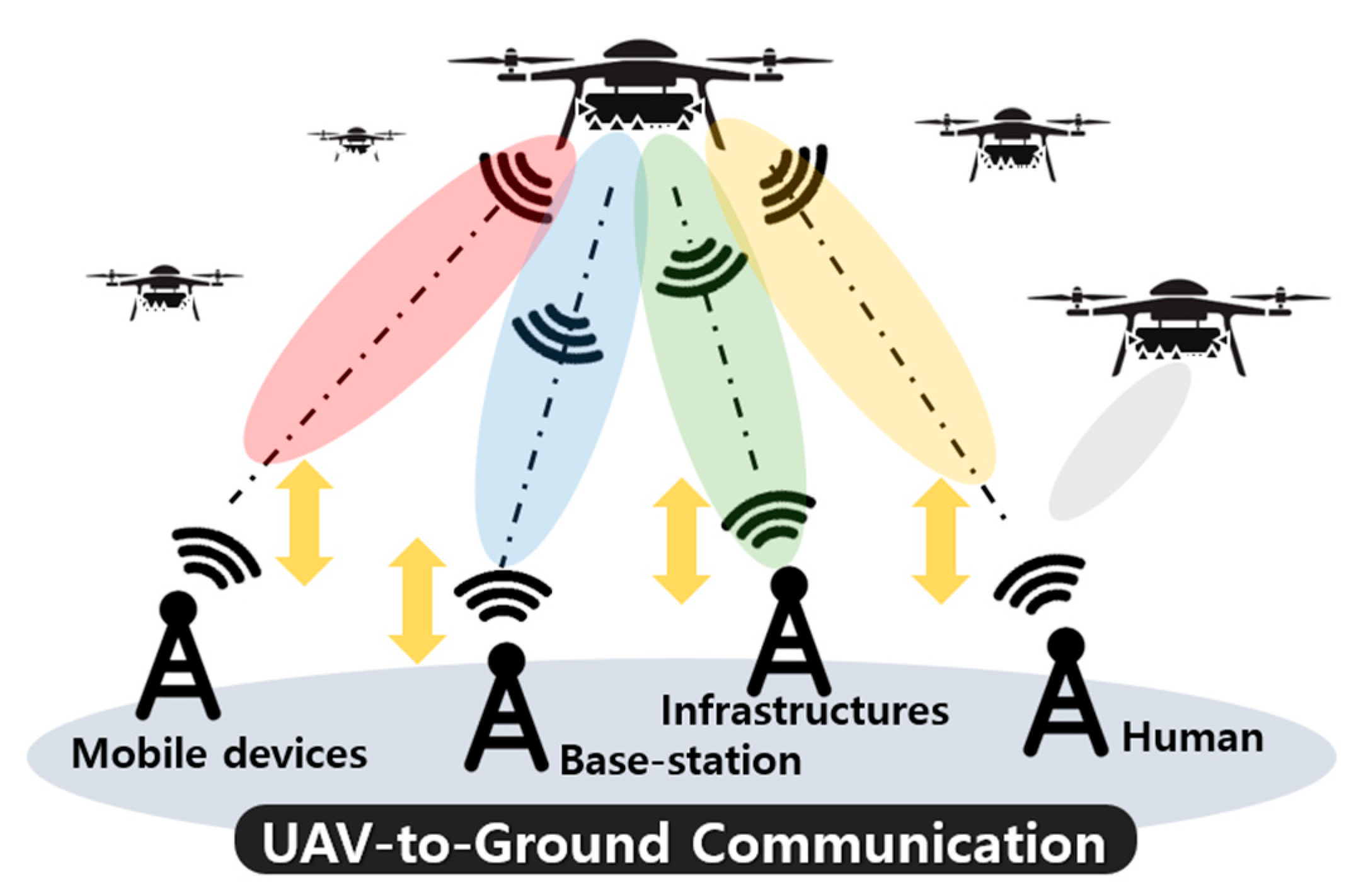
:1. Introduction
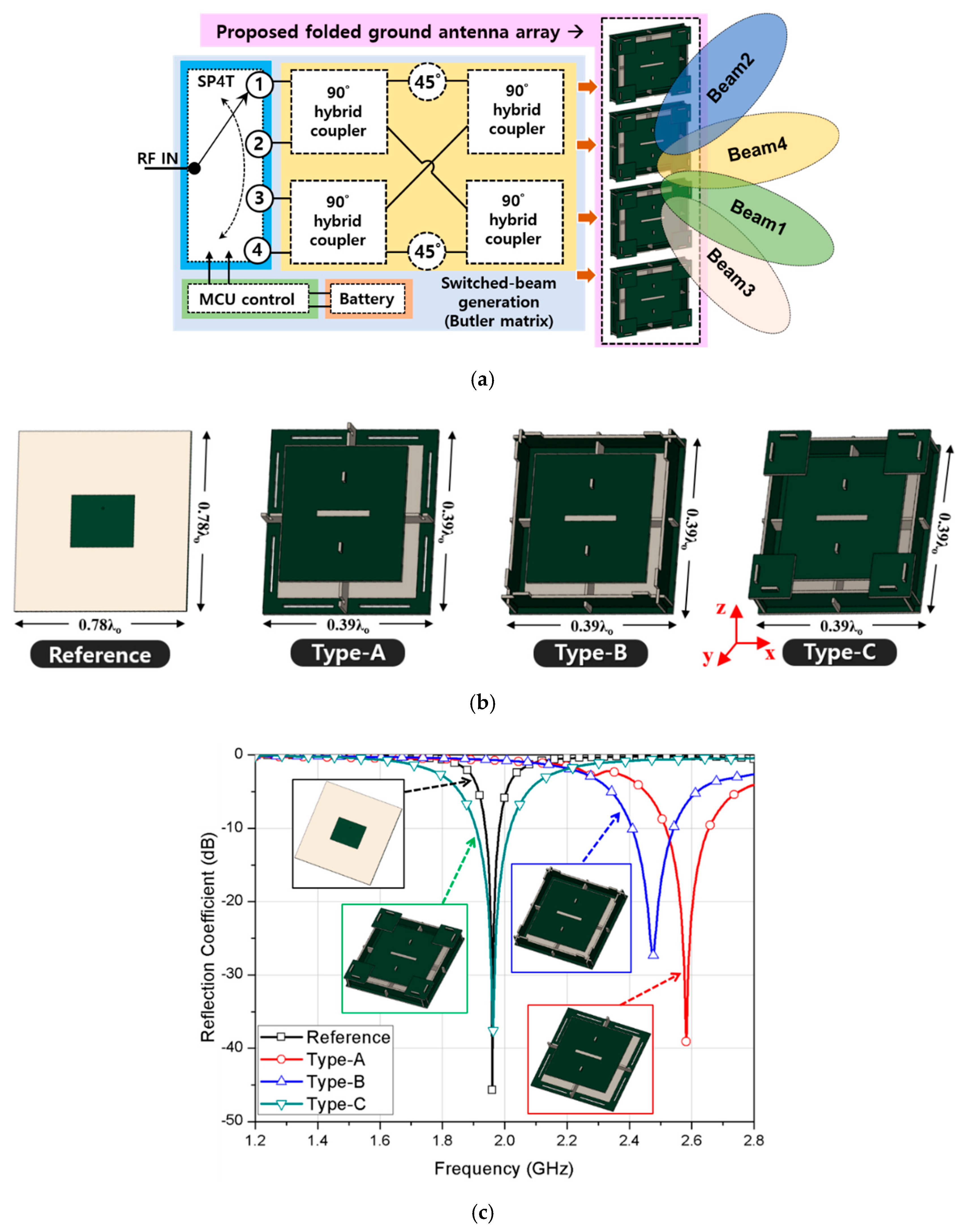
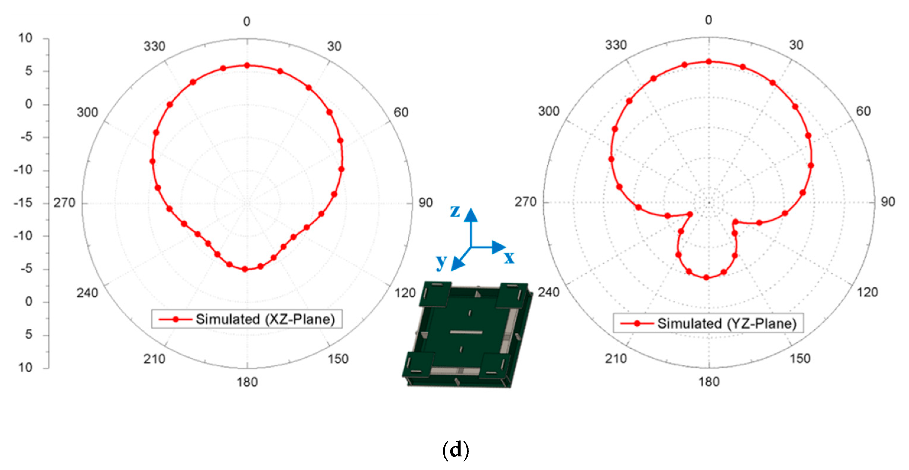
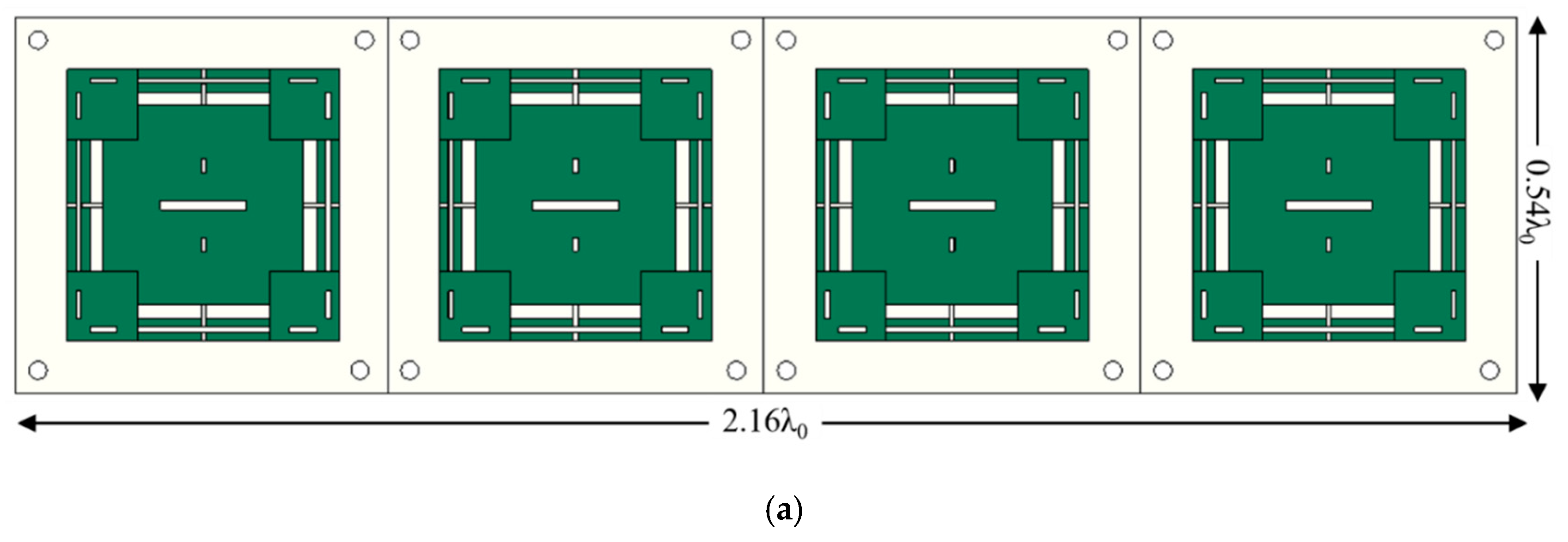
2. Design of the Proposed Structure
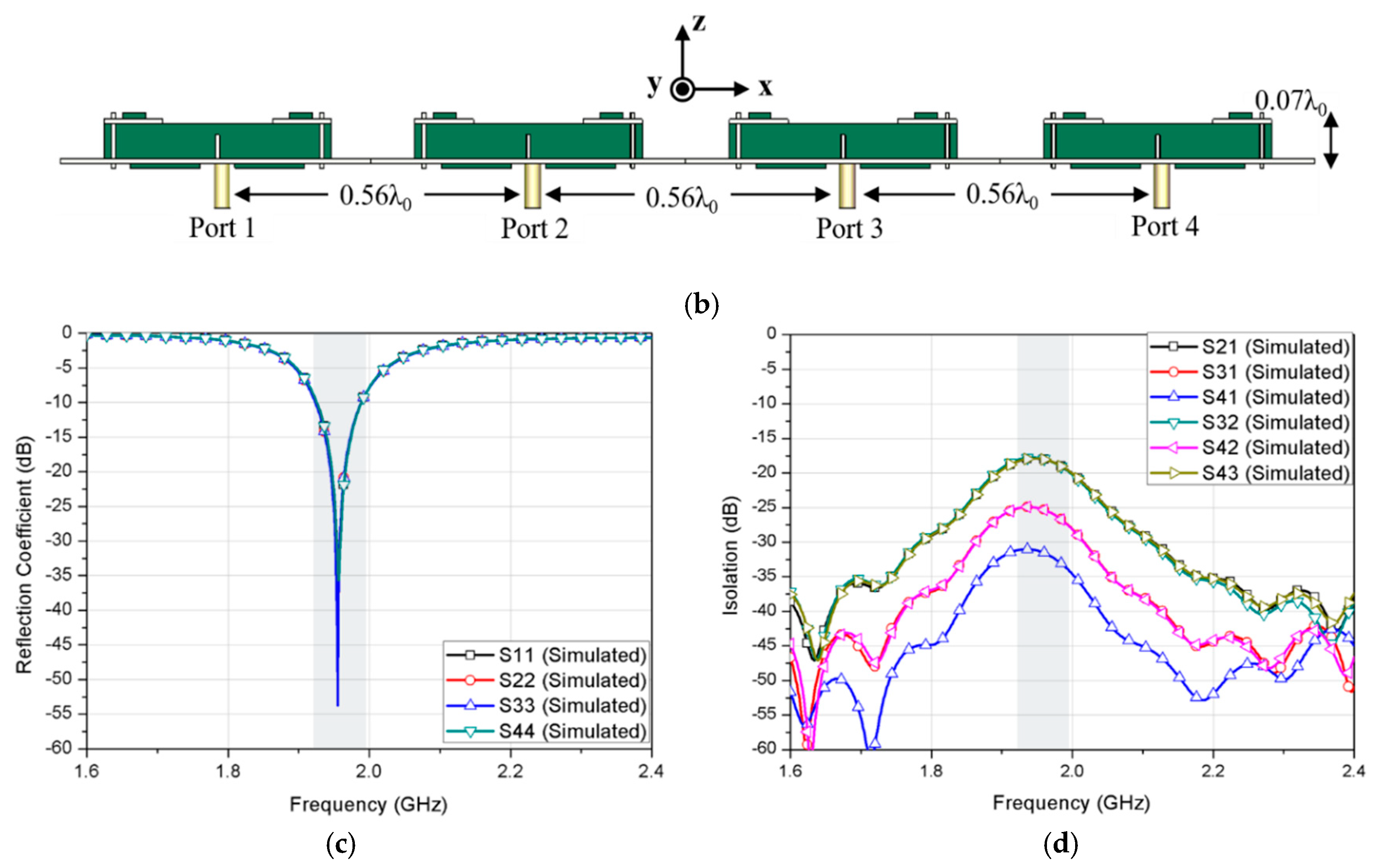
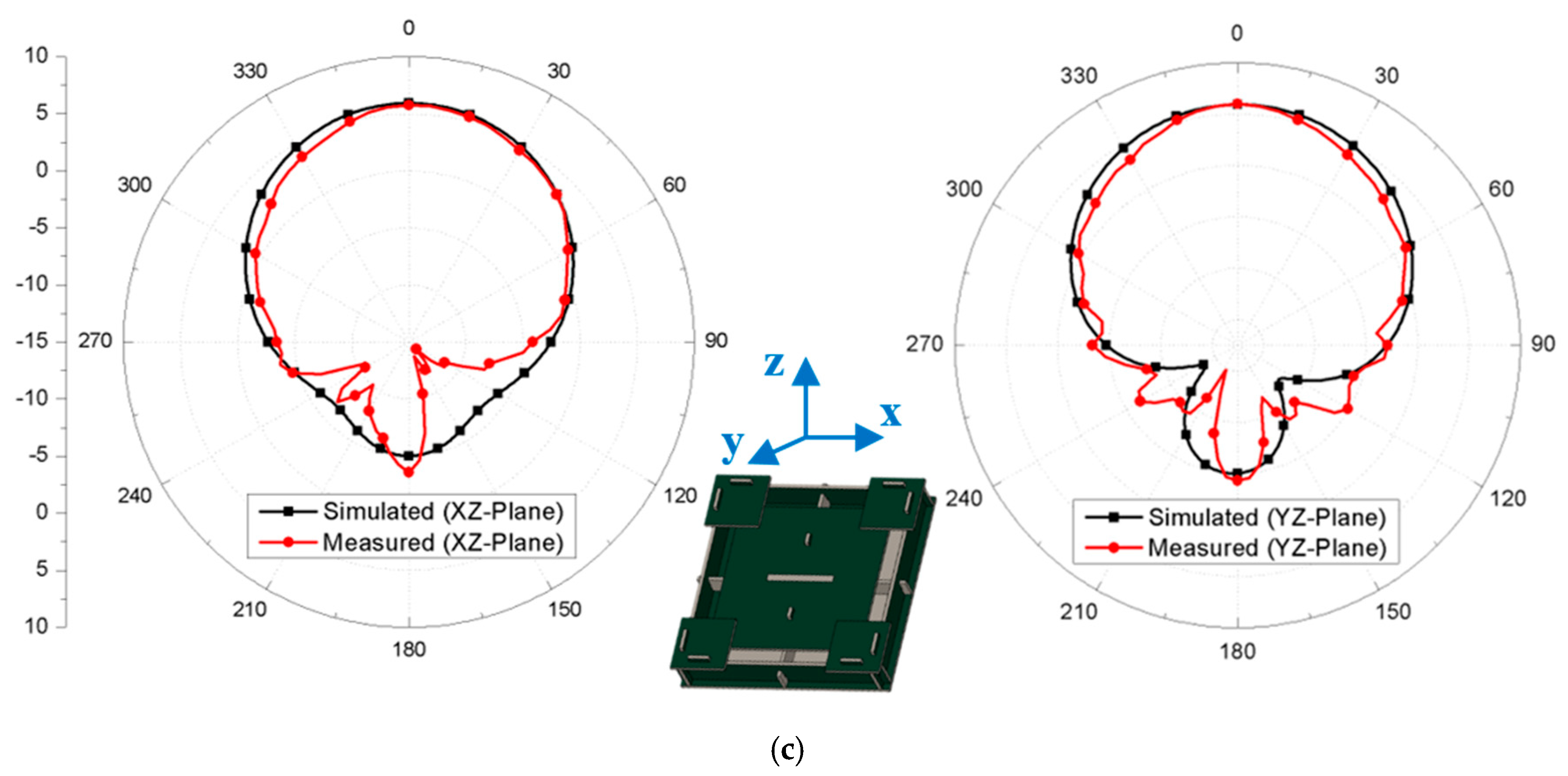
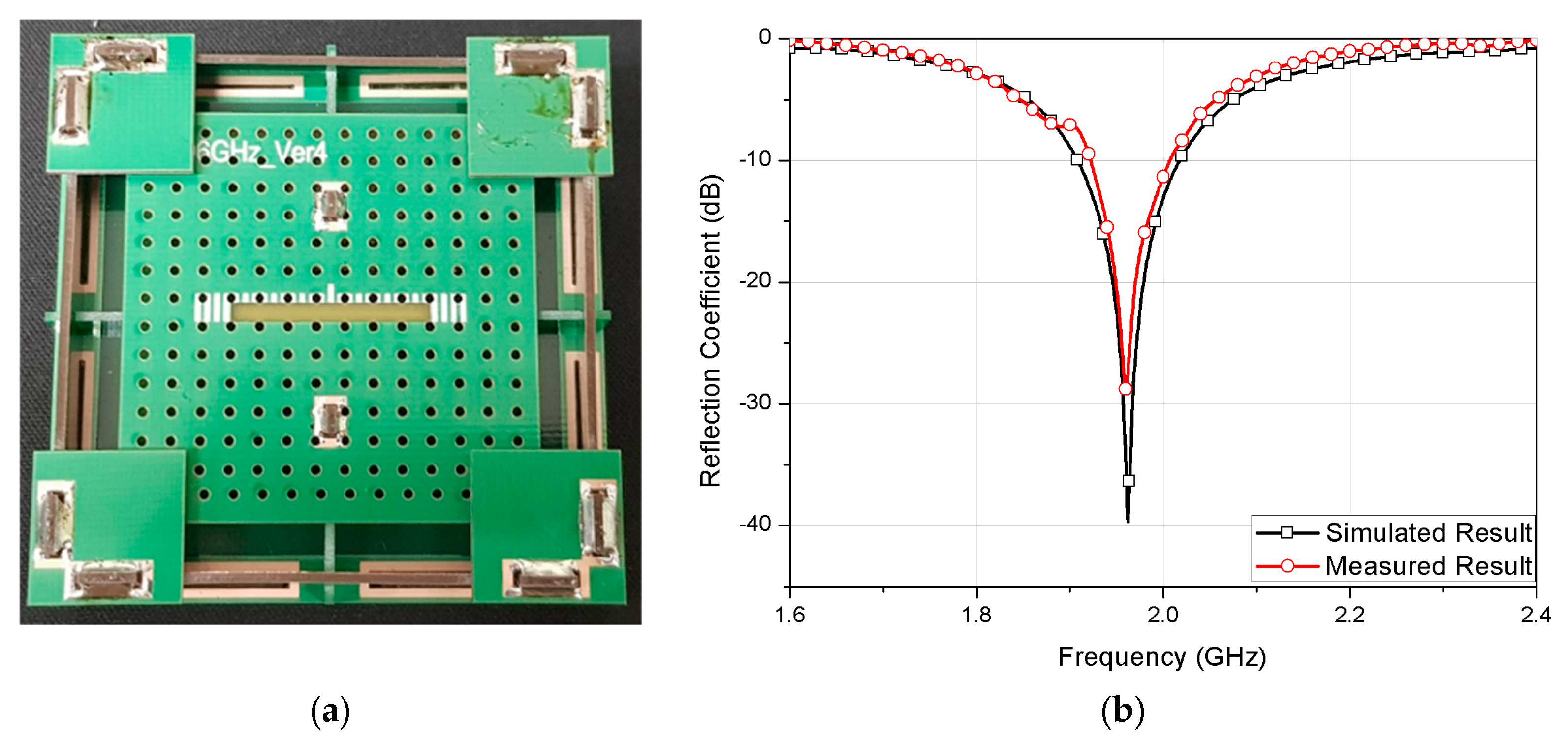
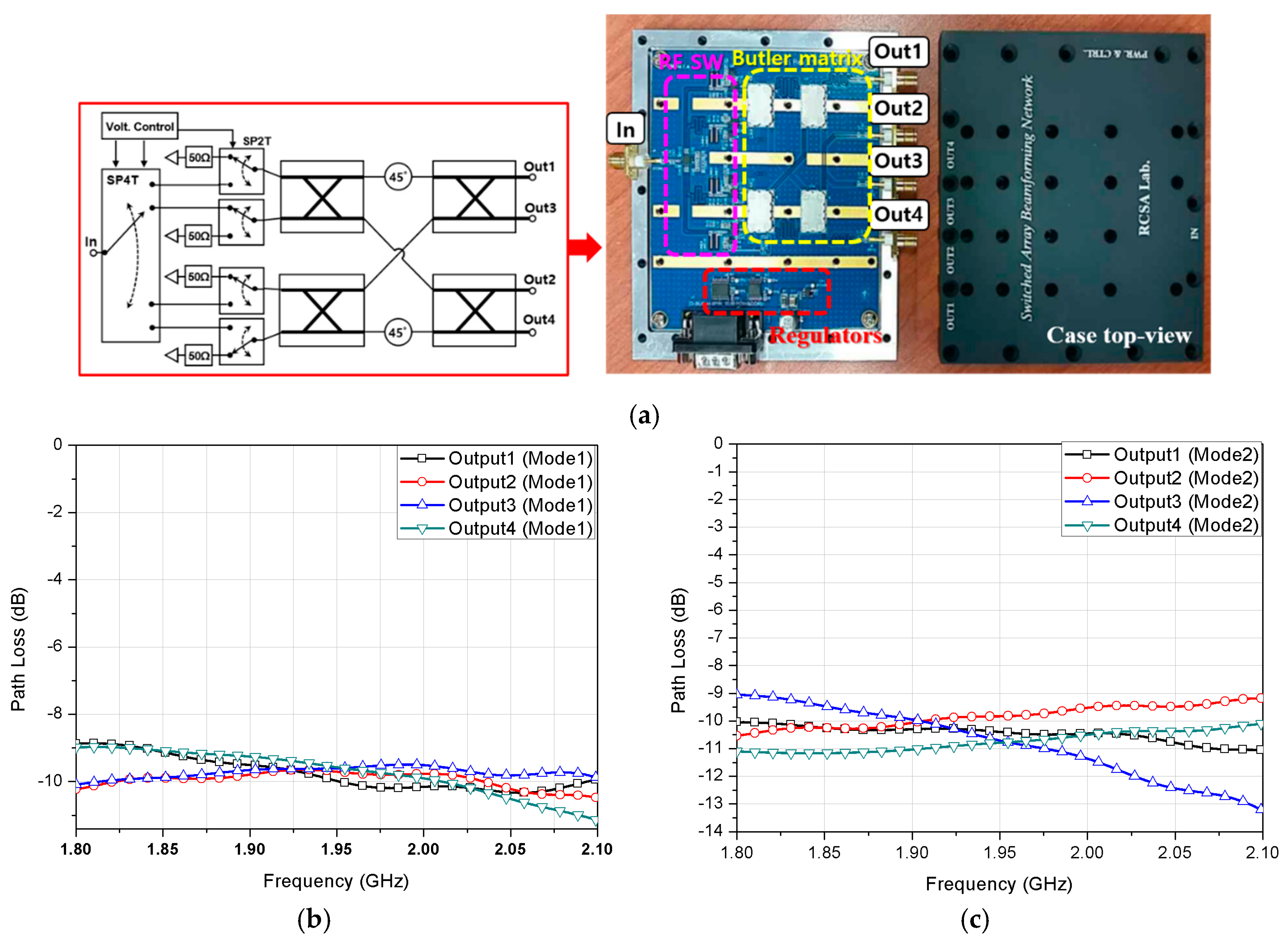
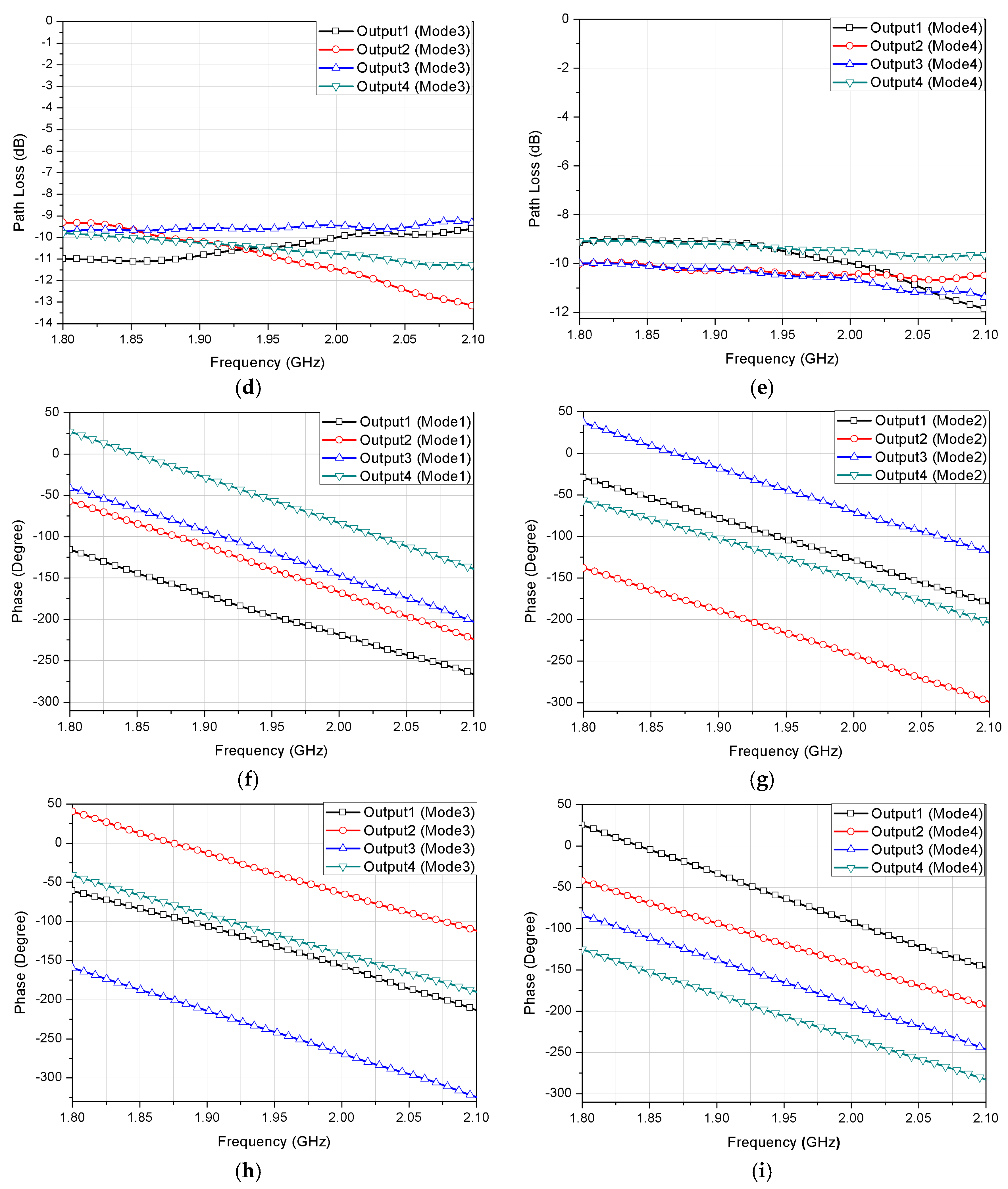
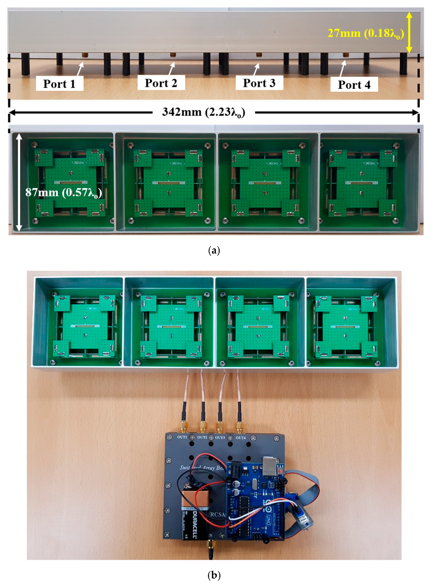
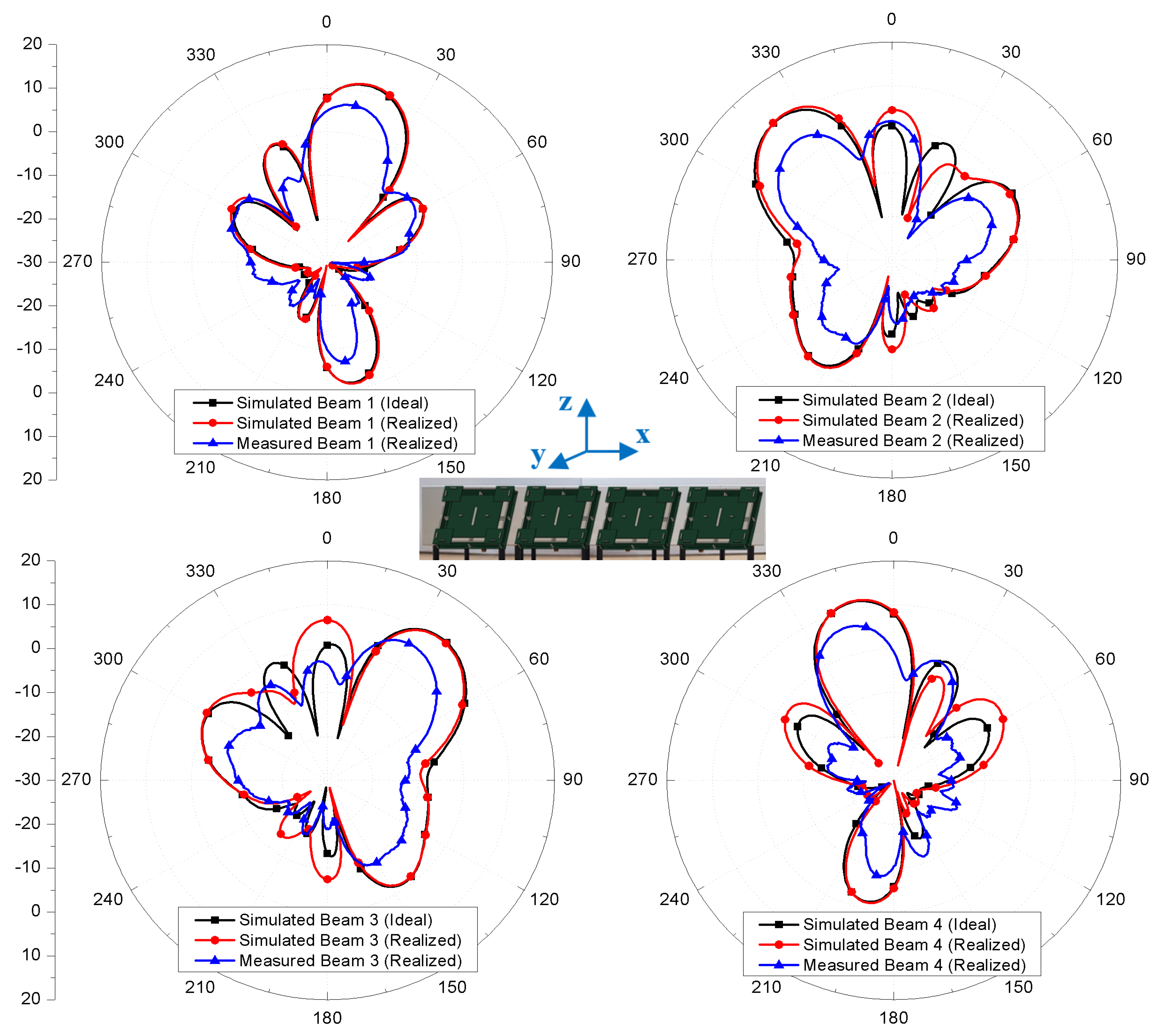
3. Measured Results
4. Conclusions
Author Contributions
Funding
Acknowledgments
Conflicts of Interest
References
- Grimaccia, F.; Bonfante, F.; Battipede, M.; Maggiore, P.; Filippone, E. Risk Analysis of the Future Implementation of a Safety Management System for Multiple RPAS Based on First Demonstration Flights. Electronics 2017, 6, 50. [Google Scholar] [CrossRef]
- Wan, P.; Hao, B.; Li, Z.; Ma, X.; Zhao, Y. Accurate Estimation the Scanning Cycle of the Reconnaissance Radar Based on a Single Unmanned Aerial Vehicle. IEEE Access 2017, 5, 22871–22879. [Google Scholar] [CrossRef]
- Baek, H.; Lim, J. Design of Future UAV-Relay Tactical Data Link for Reliable UAV Control and Situational Awareness. IEEE Commun. Mag. 2018, 56, 144–150. [Google Scholar] [CrossRef]
- Kim, S.J.; Cho, J.; Cote, M.J. Drone-Aided Healthcare Services for Patients with Chronic Diseases in Rural Areas. J. Intell. Robot. Syst. 2017, 88, 163–180. [Google Scholar] [CrossRef]
- Mitcheson, P.D.; Boyle, D.; Kkelis, G.; Yates, D.; Saenz, J.A.; Aldhaher, S.; Yeatman, E. Energy-Autonomous Sensing Systems Using Drones. In Proceedings of the 2017 IEEE Sensors, Glasgow, UK, 29 October–1 November 2017. [Google Scholar]
- Ullah, H.; Nair, N.G.; Moore, A.; Nugent, C.; Muschamp, P.; Cuevas, M. 5G Communication: An Overview of Vehicle-to-Everything, Drones, and Healthcare Use-Cases. IEEE Access 2019, 7, 37251–37268. [Google Scholar] [CrossRef]
- Kovalchukov, R.; Moltchanov, D.; Samuylov, A.; Ometov, A.; Andreev, S.; Koucheryavy, Y.; Samouylov, K. Analyzing Effects of Directionality and Random Heights in Drone-Based mmWave Communication. IEEE Trans. Veh. Technol. 2018, 67, 10064–10069. [Google Scholar] [CrossRef]
- Naqvi, S.A.R.; Hassan, S.A.; Pervaiz, H.; Ni, Q. Drone-Aided Communication as a Key Enabler for 5G and Resilient Public Safety Networks. IEEE Commun. Mag. 2018, 56, 36–42. [Google Scholar] [CrossRef] [Green Version]
- Fotouhi, A.; Ding, M.; Hassan, M. Flying Drone Base Stations for Macro Hotspots. IEEE Access 2018, 6, 19530–19539. [Google Scholar] [CrossRef]
- Hildmann, H.; Kovacs, E. Review: Using Unmanned Aerial Vehicles (UAVs) as Mobile Sensing Platforms (MSPs) for Disaster Response, Civil Security and Public Safety. Drones 2019, 3, 59. [Google Scholar] [CrossRef] [Green Version]
- Park, K.; Joung, J.; Lim, S.; Lee, H.L. A Compact Crossed Inverted-V Antenna with a Common Reflector for Polarization Diversity in the IoT. Electronics 2019, 8, 637. [Google Scholar] [CrossRef] [Green Version]
- Khang, S.T.; Yu, J.W.; Lee, W.S. Compact folded dipole rectenna with RF-based energy harvesting for IoT smart sensors. Electron. Lett. 2015, 51, 926–928. [Google Scholar] [CrossRef]
- Bhatti, R.A.; Im, Y.T.; Park, S.O. Compact PIFA for mobile terminals supporting multiple cellular and non-cellular standards. IEEE Trans. Antennas Propag. 2009, 57, 2534–2540. [Google Scholar] [CrossRef]
- Saed, M.A.; Yadla, R. Microstrip-fed low profile and compact dielectric resonator antennas. Prog. Electromagn. Res. 2006, 56, 151–162. [Google Scholar] [CrossRef] [Green Version]
- Samsuzzaman, M.D.; IsLam, M.T.; Singh, M.S.J. A Compact Printed Monopole Antenna with Wideband Circular Polarization. IEEE Access 2018, 6, 54713–54725. [Google Scholar] [CrossRef]
- Azadegan, R.; Sarabandi, K. A novel approach for miniaturization of slot antennas. IEEE Trans. Antennas Propag. 2003, 51, 421–429. [Google Scholar] [CrossRef] [Green Version]
- Quan, X.; Li, R.; Cui, Y.; Tentzeris, M.N. Analysis and Design of a Compact Dual-Band Directional Antenna. IEEE Antennas Wirel. Propag. Lett. 2012, 11, 547–550. [Google Scholar] [CrossRef] [Green Version]
- Guo, J.; Zou, Y.; Liu, C. Compact Broadband Crescent Moon-Shape Patch-Pair Antenna. IEEE Antennas Propag. Mag. 2011, 10, 435–437. [Google Scholar]
- Wen, L.H.; Gao, S.; Luo, Q.; Mao, C.X.; Hu, W.; Yin, Y.; Zhou, Y.; Wang, Q. Compact Dual-Polarized Shared-Dipole Antennas for Base Station Applications. IEEE Trans. Antennas Propag. 2018, 66, 6826–6834. [Google Scholar] [CrossRef] [Green Version]
- Wang, M.S.; Zhu, X.Q.; Guo, Y.X.; Wu, W. Compact Circularly Polarized Patch Antenna with Wide Axial-Ratio Beamwidth. IEEE Antennas Wirel. Propag. Lett. 2018, 17, 714–718. [Google Scholar] [CrossRef]
- Wong, H.; So, K.K.; Ng, K.B.; Luk, K.M.; Chan, C.H.; Xue, Q. Virtually shorted patch antenna for circular polarization. IEEE Antennas Wirel. Propag. Lett. 2010, 9, 1213–1216. [Google Scholar] [CrossRef]
- Kim, K.-S.; Kim, G.; Chae, S.-C.; Jo, H.-W.; Yu, J.-W.; Lee, H.L. A Compact Circular Polarization Antenna Using Folded Ground Elements. IEEE Trans. Antennas Propag. 2019, 67, 3472–3477. [Google Scholar] [CrossRef]
- Row, J.S.; Tsai, C.W. Pattern Reconfigurable Antenna Array with Circular Polarization. IEEE Trans. Antennas Propag. 2016, 64, 1025–1030. [Google Scholar] [CrossRef]
- Row, J.S.; Huang, Y.J. Reconfigurable Antenna with Switchable Broadside and Conical Beams and Switchable Linear Polarized Patterns. IEEE Trans. Antennas Propag. 2018, 66, 3752–3756. [Google Scholar] [CrossRef]
- Chen, S.L.; Qin, P.Y.; Lin, W.; Guo, Y.J. Pattern-Reconfigurable Antenna with Five Switchable Beams in Elevation Plane. IEEE Antennas Wirel. Propag. Lett. 2018, 17, 454–457. [Google Scholar] [CrossRef] [Green Version]
- Kim, S.; Yoon, S.; Lee, Y.; Shin, H. A Miniaturized Butler Matrix Based Switched Beamforming Antenna System in a Two-Layer Hybrid Stackup Substrate for 5G Applications. Electronics 2019, 8, 1232. [Google Scholar] [CrossRef] [Green Version]
- Mousavi, Z.; Rezaei, P. Millimetre-wave beam-steering array antenna by emphasising on improvement of Butler matrix features. IET Microw. Antennas Propag. 2019, 13, 1287–1292. [Google Scholar] [CrossRef]
- Trinh-Van, S.; Lee, J.M.; Yang, Y.; Lee, K.-Y.; Hwang, K.C. A Sidelobe-Reduced, Four-Beam Array Antenna Fed by a Modified 4 × 4 Butler Matrix for 5G Applications. IEEE Trans. Antennas Propag. 2019, 67, 4528–4536. [Google Scholar] [CrossRef]
- Cheng, X.; Yao, Y.; Tomura, T.; Hirokawa, J.; Yu, T.; Yu, J.; Chen, X. A Compact Multi-Beam End-Fire Circularly Polarized Septum Antenna Array for Millimeter-Wave Applications. IEEE Access 2018, 6, 62784–62792. [Google Scholar] [CrossRef]


| Mode | Output1 | Output2 | Output3 | Output4 | |||||
|---|---|---|---|---|---|---|---|---|---|
| Measured | Ideal | Measured | Ideal | Measured | Ideal | Measured | Ideal | ||
| MAG (dB) | 1 | −10.0 | −9 | −9.7 | −9 | −9.5 | −9 | −9.6 | −9 |
| 2 | −10.4 | −9 | −9.8 | −9 | −10.8 | −9 | −10.7 | −9 | |
| 3 | −10.4 | −9 | −10.9 | −9 | −9.5 | −9 | −10.5 | −9 | |
| 4 | −9.6 | −9 | −10.4 | −9 | −10.5 | −9 | −9.4 | −9 | |
| PH (°) | 1 | 159 | 159 | −145 | −156 | −125 | −111 | −61 | −66 |
| 2 | −109 | −109 | 138 | 116 | −49 | −19 | −131 | −154 | |
| 3 | −136 | −136 | −44 | −1 | 114 | 134 | −122 | −91 | |
| 4 | −69 | −69 | −124 | −114 | −170 | −159 | 149 | 156 | |
© 2019 by the authors. Licensee MDPI, Basel, Switzerland. This article is an open access article distributed under the terms and conditions of the Creative Commons Attribution (CC BY) license (http://creativecommons.org/licenses/by/4.0/).
Share and Cite
Kim, Y.-J.; Kim, Y.-B.; Dong, H.-J.; Cho, Y.S.; Lee, H.L. Compact Switched-Beam Array Antenna with a Butler Matrix and a Folded Ground Structure. Electronics 2020, 9, 2. https://doi.org/10.3390/electronics9010002
Kim Y-J, Kim Y-B, Dong H-J, Cho YS, Lee HL. Compact Switched-Beam Array Antenna with a Butler Matrix and a Folded Ground Structure. Electronics. 2020; 9(1):2. https://doi.org/10.3390/electronics9010002
Chicago/Turabian StyleKim, Young-Jun, Ye-Bon Kim, Hyun-Jun Dong, Yong Soo Cho, and Han Lim Lee. 2020. "Compact Switched-Beam Array Antenna with a Butler Matrix and a Folded Ground Structure" Electronics 9, no. 1: 2. https://doi.org/10.3390/electronics9010002
APA StyleKim, Y.-J., Kim, Y.-B., Dong, H.-J., Cho, Y. S., & Lee, H. L. (2020). Compact Switched-Beam Array Antenna with a Butler Matrix and a Folded Ground Structure. Electronics, 9(1), 2. https://doi.org/10.3390/electronics9010002