Article

Joint Design and Performance Analysis of a Full-Duplex UAV Legitimate Surveillance System

1
School of Cyber Science and Engineering, Southeast University, Nanjing 210096, China
2
National Mobile Communications Research Laboratory, Southeast University, Nanjing 210096, China
3
Purple Mountain Laboratories, Nanjing 211100, China
*
Author to whom correspondence should be addressed.
Electronics 2020, 9(3), 407; https://doi.org/10.3390/electronics9030407
Submission received: 21 January 2020 / Revised: 25 February 2020 / Accepted: 26 February 2020 / Published: 28 February 2020
(This article belongs to the Special Issue RF/Microwave Antenna, Circuit, and System Design for UAV Applications)

Abstract

:
In this paper, we propose a legitimate surveillance system, where a full-duplex unmanned aerial vehicle (UAV) legitimate monitor with simultaneous passive surveilling and active jamming is deployed to monitor a suspicious communication link between a dubious pair on the ground. Two different scenarios for the UAV, single-input single-output (SISO) and multiple-input multiple-output (MIMO), are studied. Three low-complexity linear beamforming schemes, transmit zero-forcing (TZF)/maximum ratio combing (MRC), maximum ratio transmission (MRT)/receive zero-forcing (RZF), and maximum ratio transmission (MRT)/maximum ratio combing (MRC) are considered for MIMO UAV. The surveilling non-outage probability is derived and analyzed, and optimal jamming power is obtained. Simulation and numerical results are used to validate the derivation.

1. Introduction

Unmanned aerial vehicles (UAVs) will probably be widely used in on-demand mobile communication networks through flexible deployment. On one hand, since the UAV operates in relatively high attitude with a dominant line-of-sight (LoS) channel environment, the air-to-ground channel provides a superior communication channel in the cellular network compared to heavily fading ground channels. On the other hand, the UAV can make use of spatial freedom for best performance. The scenes in which the UAV participates in wireless communication are mainly divided into four categories: UAV aerial base station [1,2,3], UAV aerial legitimate terminals [4,5,6], UAV friendly relays [7,8,9] and UAV friendly jamming [10,11].
Wireless surveillance equipment can be used to monitor a suspicious communication link. The ground monitor is studied in [12,13,14,15]. In order to ensure effective surveilling, a novel approach, namely, proactive surveilling via cognitive jamming, is proposed in [12,13], where the legitimate monitor uses full-duplex techniques to simultaneously receive suspicious information and interfere with the suspicious link. In reference [12], the surveilling performance of the legitimate monitor is analyzed in fading channel scenarios. In reference [13], the surveilling performance of the legitimate monitor is further investigated in communication scenarios that are delay-sensitive and delay-insensitive. Authors in reference [14] propose a new proactive surveilling approach, where the legitimate monitor acts as a spoofing relay to change the suspicious transmission rate for enhancing the surveilling performance. Later in reference [15], under full-duplex conditions, multi-antenna technology is used to effectively eliminate self-interference of the legitimate monitor and ensure that the surveilling rate is greater than the suspicious transmission rate for successful surveilling.
However, a ground surveillance link suffers from severe fading communication. A UAV provides an advantageous surveilling channel for the surveilling communication link and can be equipped with a series of sensors and execution equipment to perform corresponding surveillance tasks [16]. The authorities might detect two radio stations communicating by radio for doing some illegal activities, so they send a UAV to surveil the communication and want to know the optimal strategy to improve the surveilling performance.
Compared with the ground monitor, UAV operates in relatively high attitude with a dominant LoS channel environment. As such, the UAV has good visibility and better channel quality to receive dubious information from the transmitter of a suspicious link, together with a better jamming effect on the receiver of suspicious link. Therefore, the UAV monitor is worth further investigation. In reference [17], the scenario that a legitimate UAV monitors a suspicious communication link between a dubious UAV pair via an energy-efficient track is proposed. In reference [18], the scenario that a legitimate UAV monitor a ground suspicious relay network is proposed, where the source transmits the dubious information to the destination only via the relay. In reference [19], the scenario that multiple UAVs cooperate to surveil a ground suspicious relay network with multiple relays is proposed, where UAVs operate in a half-duplex mode that either jams or surveils. Authors in reference [20] consider the scenario that a legitimate UAV surveils a suspicious communication link between a dubious UAV pair under power-limited constraints. In reference [21], authors consider the system that a legitimate UAV surveils a suspicious communication link between a dubious UAV pair with two surveilling schemes: proactive surveilling and spoofing relaying. Further, the authors consider two scenarios: enough jamming power and limited jamming power throughout flight time. However, the UAV operates in a half-duplex mode in the above studies.
The full-duplex technique is widely used in the UAV relay system [22], but is not used in the UAV legitimate surveillance system. A UAV monitor is far away from the suspicious link and the information rate received by the monitoring link is smaller than the suspicious link. Hence, a UAV monitor needs to work in a full-duplex mode to improve surveilling performance.
In this paper, we propose a legitimate surveillance system, where a full-duplex UAV legitimate monitor is introduced to monitor a suspicious communication link between a dubious pair on the ground. A UAV monitor performs passive surveilling to acquire the information of the source, together with active jamming to degrade the ability of the source to transmit suspicious messages to the destination. An LoS link with a certain probability is adopted as a ground-UAV-channel model. We then evaluate the surveilling performance of the UAV monitor with the non-outage probability.
The main contributions of this paper are summarized as follows:
  • We propose a full-duplex UAV monitor scheme which is different from [18], where a Rayleigh channel is adopted to characterize all channels. An LoS link with a certain probability is adopted for the ground-UAV-channel model.
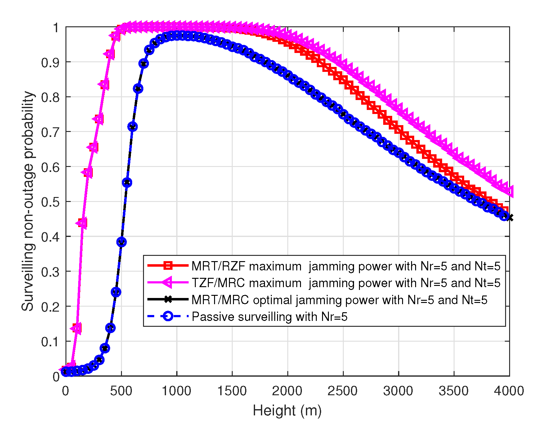
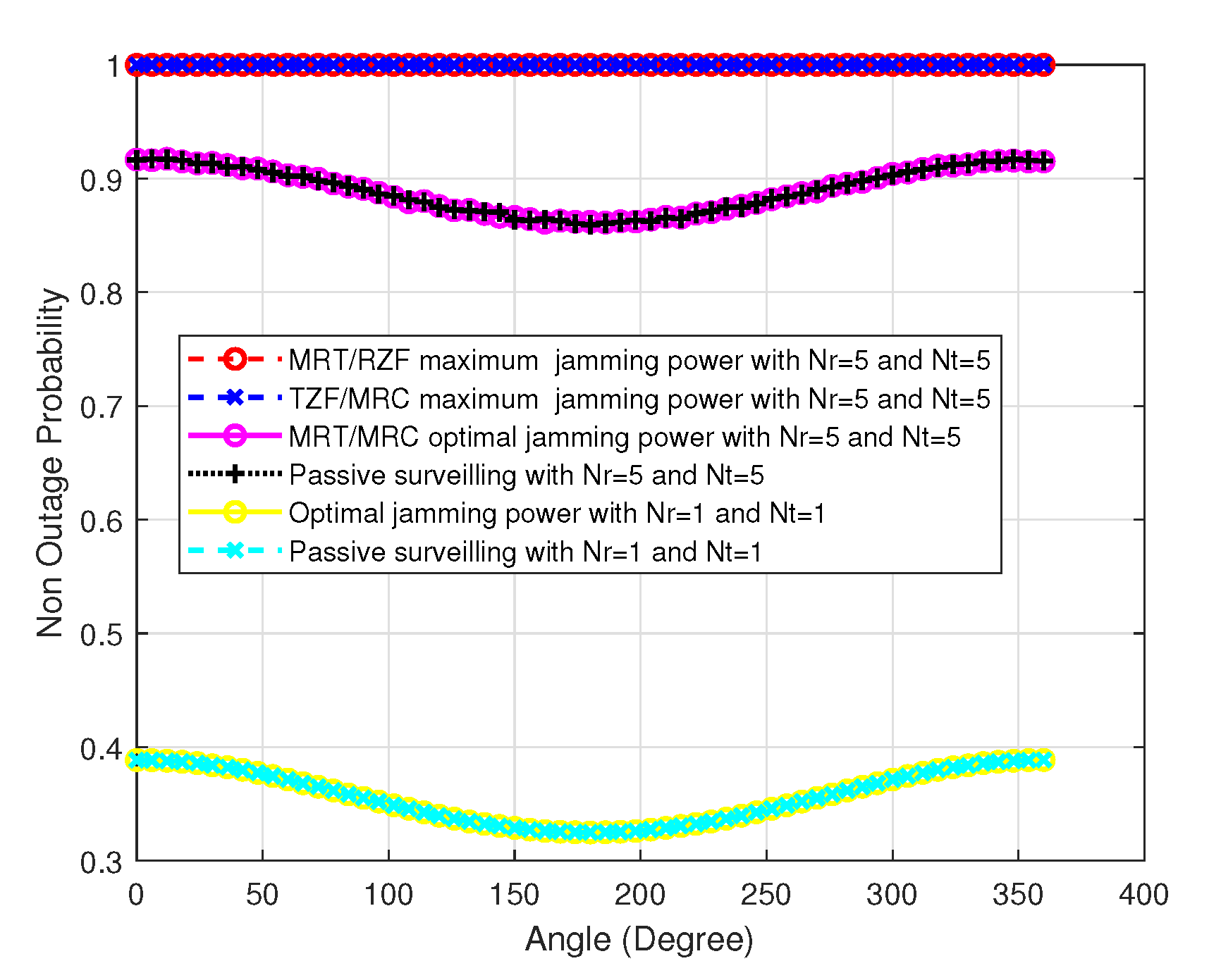
  • The surveilling non-outage probability for single-input single-output (SISO) and multiple-input multiple-output (MIMO) UAV with transmit zero-forcing (TZF)/maximum ratio combing (MRC), maximum ratio transmission (MRT)/receive zero-forcing (RZF), and maximum ratio transmission (MRT)/ maximum ratio combing (MRC) is derived.
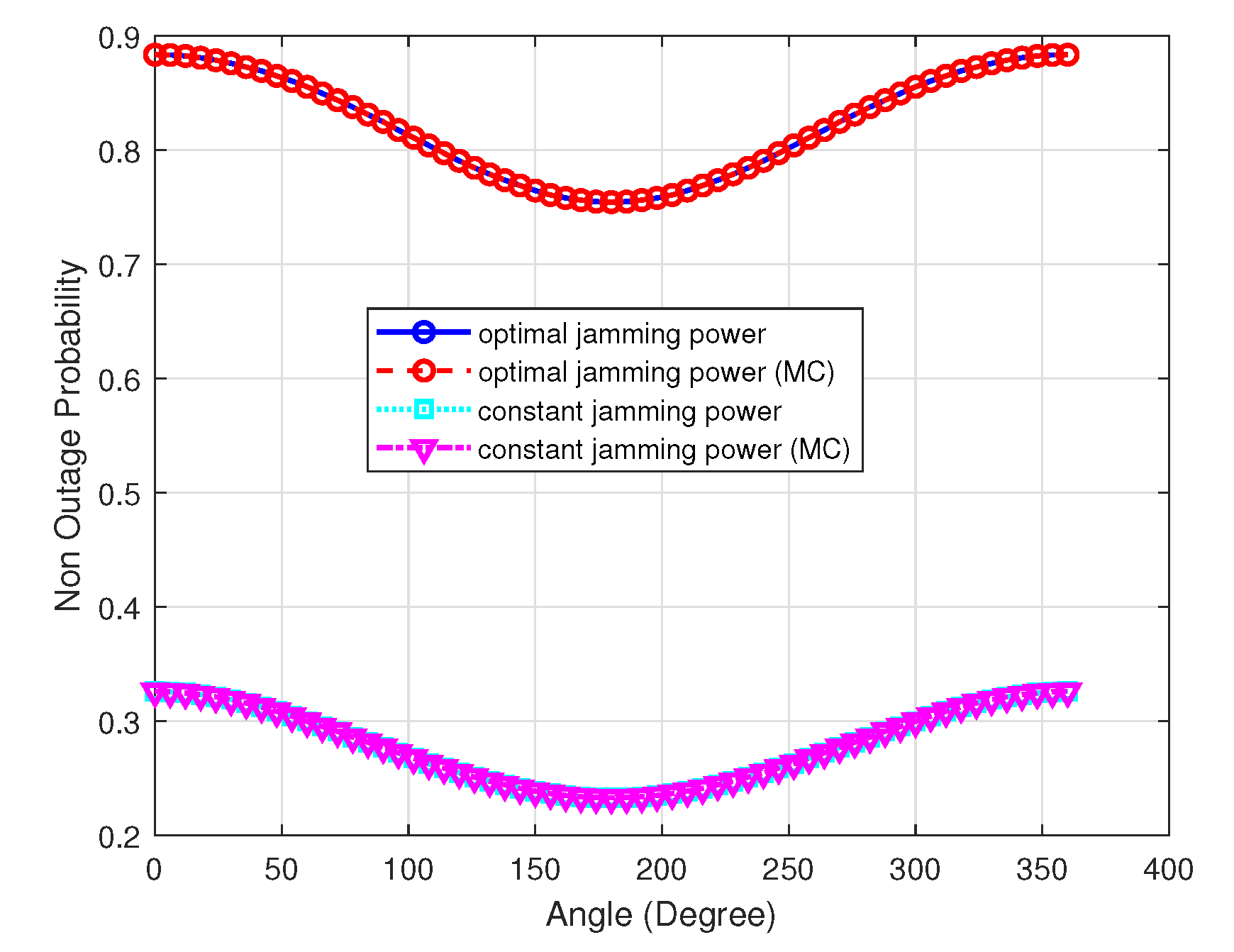
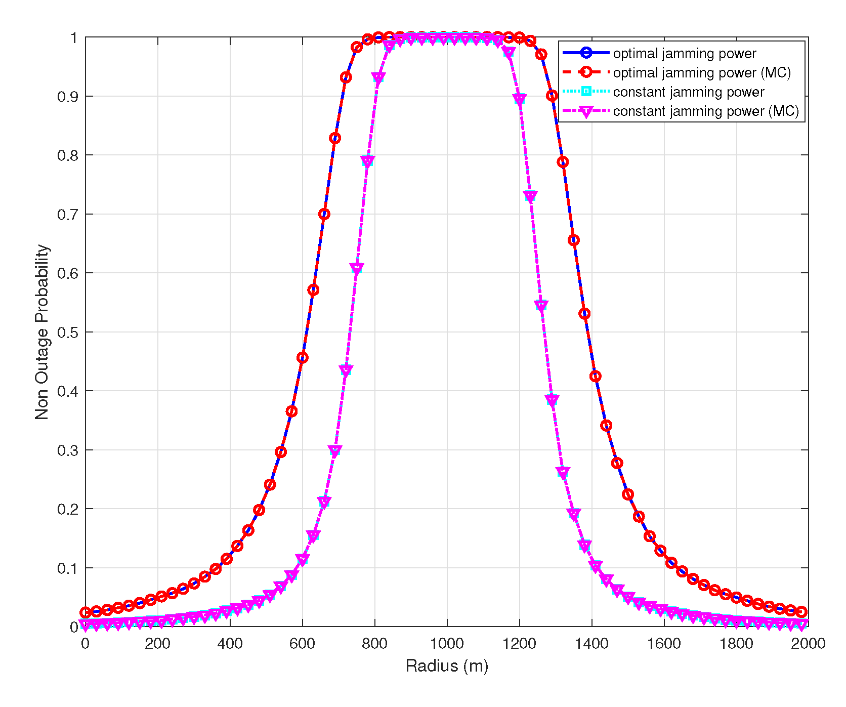
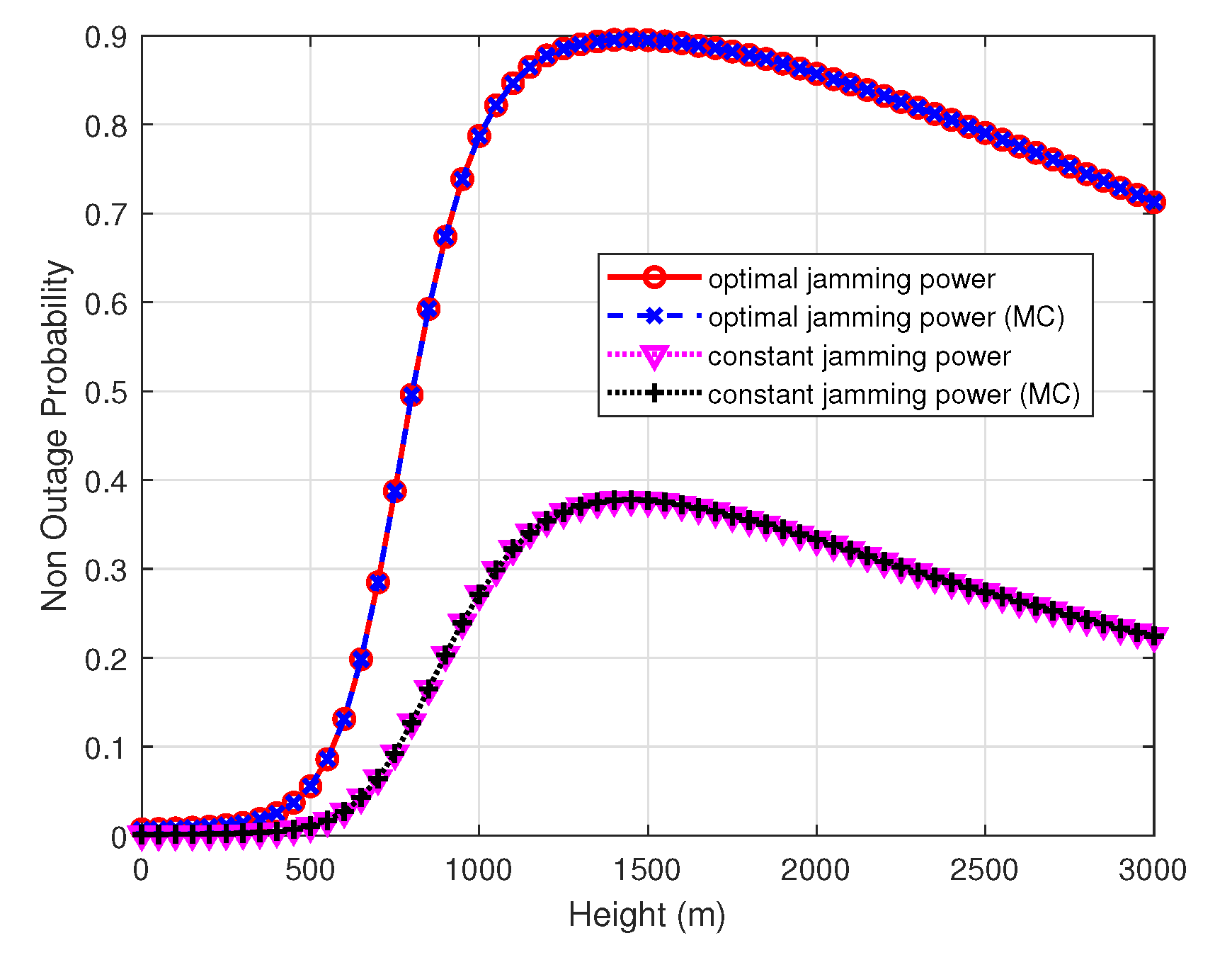
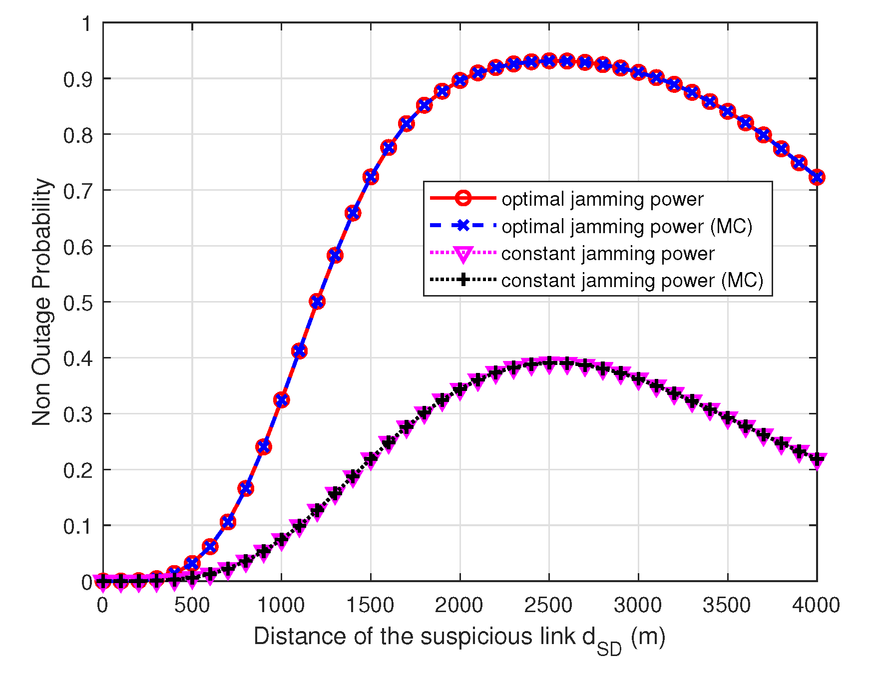
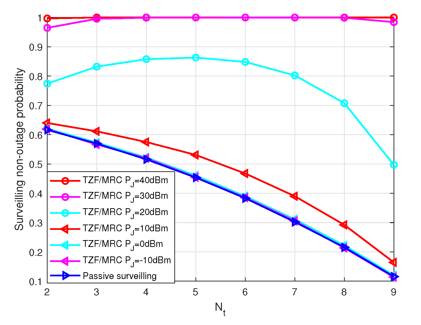
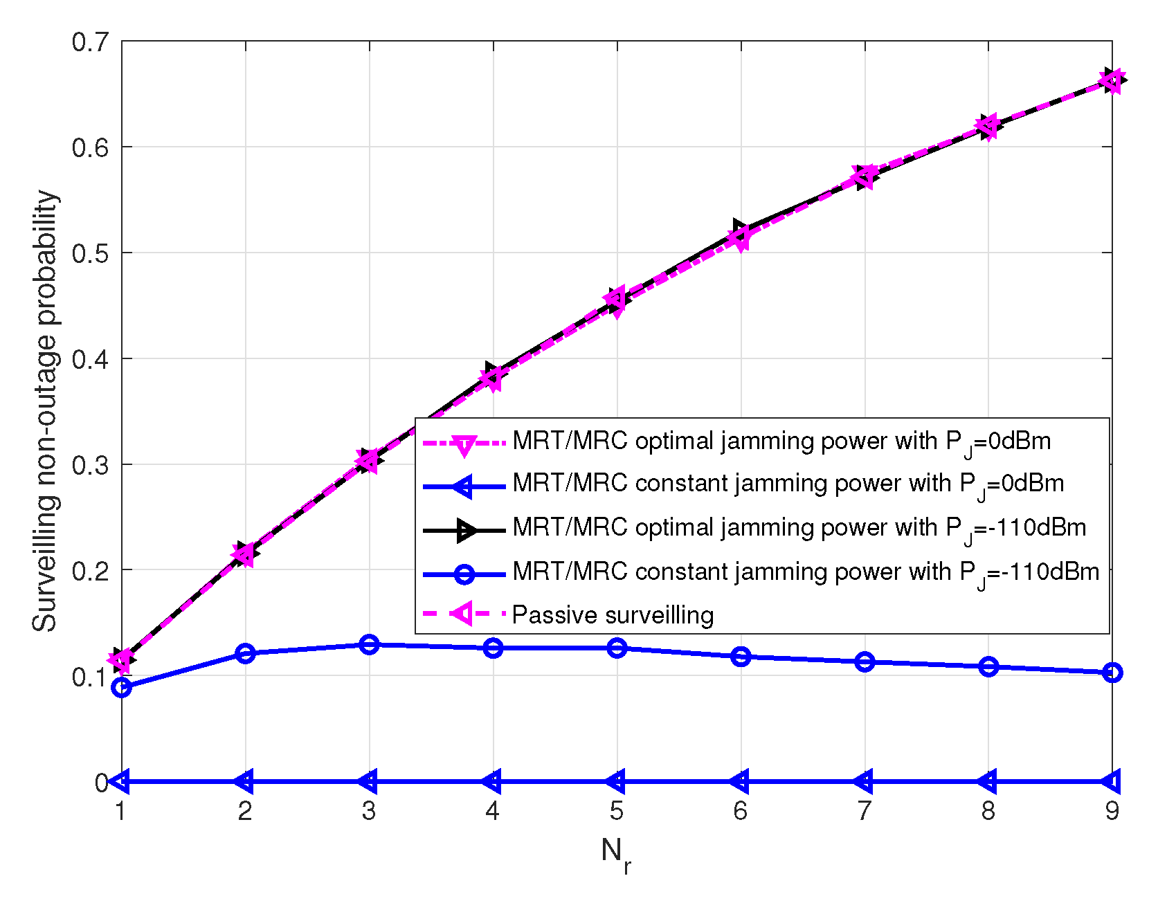
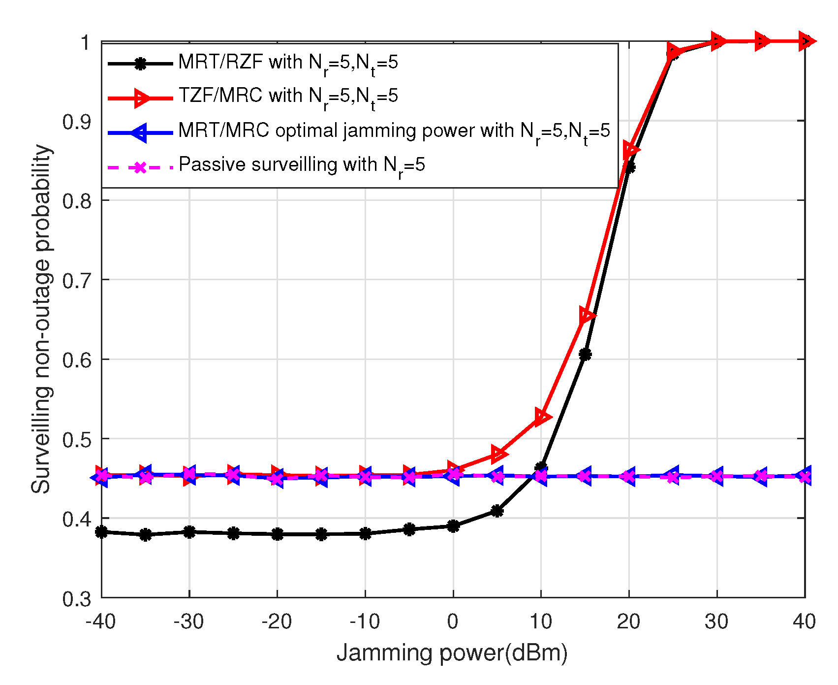
  • Optimal jamming power and 3D location of the UAV monitor that maximize the surveilling non-outage probability of the UAV monitor are determined, and the impacts of the antenna number/angle/radius/height, as well as the distance of the suspicious link, on the surveilling non-outage probability are analyzed.

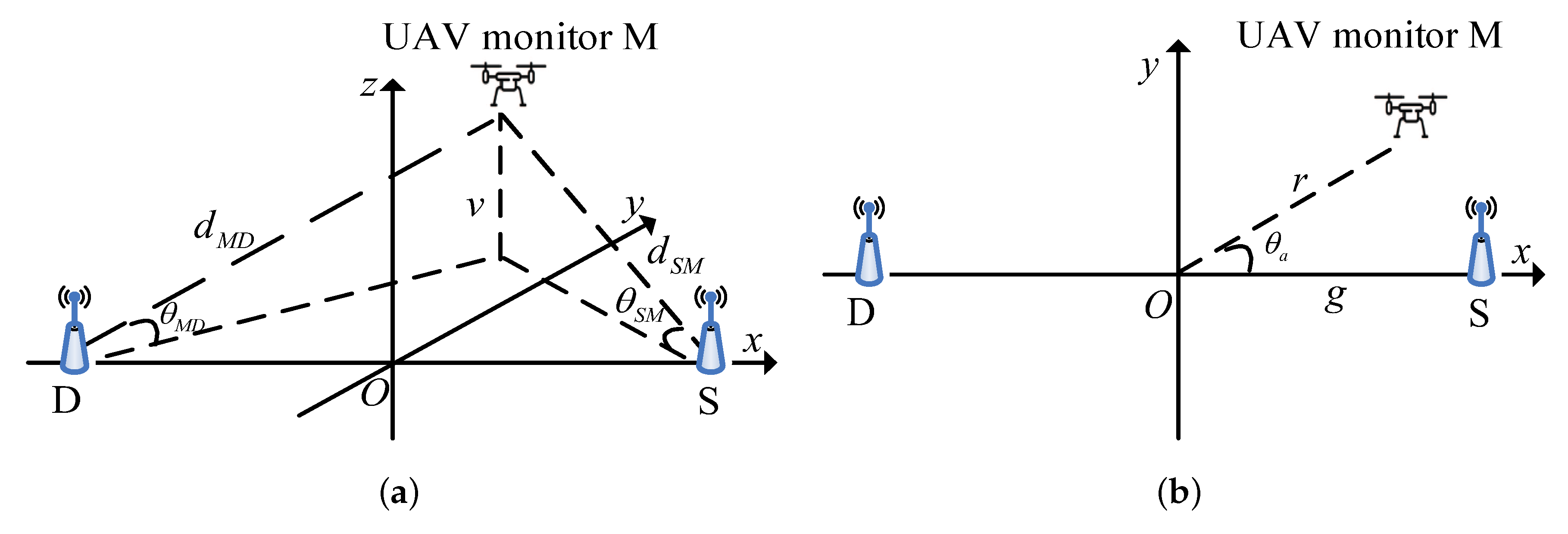
2. System Model and Problem Formulation

Consider a legitimate surveillance system where a suspicious source (S) communicates with a suspicious destination (D) on the ground, and a full-duplex UAV legitimate monitor (M) is deployed to monitor this suspicious communication link, as shown in Figure 1 with 3-D view and top view.
A UAV legitimate monitor operates in a full-duplex mode with simultaneous surveilling and jamming. Assume that the legitimate monitor has N r receiving antenna for surveilling and N t transmitting antenna for jamming, while the suspicious source and destination each have a single antenna. We adopt the three-dimensional Cartesian coordinate system, where S, D and M are located at at ( g , 0 , 0 ) , ( g , 0 , 0 ) , and ( r cos θ a , r sin θ a , v ) , respectively, g is half of the suspicious link, r is the UAV radius ranging from 0 to r m a x , θ a is the UAV azimuth angle ranging from 0 to 2 π and v is the UAV altitude ranging from 0 to v m a x . As in reference [12,22], all channel state information (CSI) is available to UAV, while the suspicious link only knows its own CSI. In practice, we can locate illegal radio stations via received signal strength (RSS), angle of arrival (AOA), time of arrival (TOA), and time difference of arrival (TDOA), etc. If the location is not known, the jamming power and 3-D location optimization cannot be used for enhancing the surveilling performance.
Denote h S M , h M D and h S D the N r × 1 channel from S to M, the 1 × N t channel from M to D and the channel from S to D, respectively. Assume h S D is Rayleigh channel and the S-D channel is modeled as β 1 h S D / d S D 4 , where β 1 denotes the channel power gain at the ground reference distance of 1 m, h S D represents the ground small-scale fading which is assumed to be zero-mean circularly symmetric complex Gaussian random variable with variance λ 1 and d S D denotes the distance between S and D. Model the self-interference channel as ρ H M M [23], where H M M denotes a Rayleigh channel with entries being independent and identically distributed (i.i.d.) zero-mean circularly symmetric complex Gaussian random variable with variance λ 2 . ρ represents the effect of self-interference with 0 < ρ < 1 .
Since UAVs operate in high altitude, the ground-UAV channels typically have a high probability of LoS link [24] as
P r L o S ( θ i ) = ( 1 + δ 1 e δ 2 θ i ) 1 ,
where δ 1 , δ 2 are constant values determined by the environment, θ i , i { S M , M D } is the elevation angle and
θ i = arcsin v d i , i { S M , M D } ,
where d S M denotes the distance between S and M and d M D denotes the distance between M and D, which can be respectively given by
d S M = ( g 2 + r 2 + v 2 2 g r cos θ a ) 1 / 2
and
d M D = ( g 2 + r 2 + v 2 + 2 g r cos θ a ) 1 / 2 .
Note that the LoS probability in (1) increases as the elevation angle θ i , i { S M , M D } increases.
From [25], the ground-UAV channel can be modeled as a Rice fading channel and the path loss exponent and Rice factor are related to the environment and elevation angle.
We then express the path loss exponent between S (or D) and M as τ i = α 1 P r L o S ( θ i ) + α 2 and the Rician factor as K i = α 3 e δ 3 θ i , where α 1 , α 2 , α 3 , and δ 3 are constants relating to environment and frequency. Therefore, the S-M and M-D channels can be modeled as β 2 h i / d i τ i , i { S M , M D } [22], where β 2 denotes the channel power gain at the air reference distance of 1 m, h i represents the small-scale fading in the air, which is given by
h i = K i K i + 1 h ¯ i + 1 K i + 1 h ˜ i , i { S M , M D } ,
where h ¯ i is the deterministic LoS components of the channel between S (or D) and M satisfying t r a c e ( h ¯ S M h ¯ S M ) = N r and t r a c e ( h ¯ M D h ¯ M D ) = N t , respectively. h ˜ S M C N r × 1 , h ˜ M D C 1 × N t respectively denotes the scattered components of the channel between S (or D) and M, the elements of which are assumed to be i.i.d. circular symmetric complex Gaussian random variables with zero mean and unit variance.
Therefore, the received signal at the UAV monitor M can be expressed as
y M = P S β 2 d S M τ S M h S M s + ρ P M H M M w t x + n M ,
where P S represents the transmitting power of the source and P M represents the jamming power of the UAV monitor satisfying 0 P M P J . In addition, s is the suspicious symbol with unit power sent by the source and x is the jamming symbol with unit power sent by the UAV. Further, w t is the transmit beamforming vector at UAV monitor with w t = 1 . Finally, n M is the zero-mean additive white Gaussian noise (AWGN) at the UAV monitor M with the variance E { n M n M } = σ M 2 I N r .
Assume that UAV adopts linear receiver w r with w r = 1 for signal detection, hence, the output of linear filter w r can be expressed as
y M ˜ = w r y M = w r P S β 2 d S M τ S M h S M s + w r ρ P M H M M w t x + w r n M ,
Similarly, the signal received by the suspicious receiver D is given by
y D = P S β 1 d S D 4 h S D s + P M β 2 d M D τ M D h M D w t x + n D ,
where n D is the zero-mean AWGN at the suspicious receiver D with variance σ D 2 .
Therefore, the signal to interference-plus-noise ratio (SINR) at the destination node D and at UAV monitor M are, respectively, given by
SIN R D = P S β 1 d S D 4 | h S D | 2 P M β 2 d M D τ M D | h M D w t | 2 + σ D 2
and
SIN R M = P S β 2 d S M τ S M | w r h S M | 2 ρ P M | w r H M M w t | 2 + σ M 2 .
If SIN R M SIN R D , the legitimate monitor can reliably decode the message. It represents a successful surveilling at the legitimate monitor. If SIN R M < SIN R D , the legitimate monitor cannot correctly decode the message, then the legitimate monitor fails.
As in [15], surveilling non-outage probability P non-out = Prob ( SIN R M SIN R D ) is used to represent the successful interception performance at UAV legitimate monitor.
The main objective is to determine the optimal parameters ( P M , θ a , v , r ) for maximizing the surveilling non-outage probability. Therefore, the optimization problem can be expressed as
( P 1 ) : max P M , θ a , v , r Prob ( SIN R M SIN R D ) s . t . 0 P M P J 0 θ < 2 π 0 v v m a x 0 r r m a x .
In (P1), the convexity of the objective function is difficult to analyze, since θ a , v, r is implicit in the path loss exponent, the elevation angle, and the Rician factor. Consequently, it is difficult to obtain the optimal θ a , v and r from mathematics. However, we can deal with the problem (P1) in two steps:
First, for a fixed 3D location ( θ a , v , r ) of UAV, we find the power P M * ( θ a , v , r ) that maximizes the surveilling non-outage probability Prob ( SIN R M SIN R D ) * .
Then, we find the optimal 3D location of the UAV ( θ a * o , v * o , r * o ) to maximizes Prob ( SIN R M SIN R D ) * for 0 θ < 2 π , 0 v v m a x , 0 r r m a x . Accordingly, the value of P M * ( θ a , v , r ) associated with θ a * o , v * o , r * o is defined as P M * o .

3. Jamming Power Optimization and Performance Analysis

3.1. SISO UAV

When θ a , v, r are fixed, P1 can be simplified to
( P 2 ) : max P M Prob P S β 2 d S M τ S M | h S M | 2 ρ P M | h M M | 2 + σ M 2 P S β 1 d S D 4 | h S D | 2 P M β 2 d M D τ M D | h M D | 2 + σ D 2 s . t . 0 P M P J .
Note that the objective function of the problem (P2) is non-convex in terms of the jamming power P M and independent of the transmit power P S at the suspicious transmitter. However, problem (P2) can be reformulated as
( P 3 ) : min P M ρ P M | h M M | 2 + σ M 2 P M β 2 d M D τ M D | h M D | 2 + σ D 2 s . t . 0 P M P J .
Theorem 1. 
The optimal jamming power of the UAV can be expressed as
P M = P J if σ D 2 σ M 2 < β 2 | h M D | 2 ρ d M D τ M D | h M M | 2 , 0 o t h e r w i s e .
Proof of Theorem 1. 
Define
f ( x ) = ρ x | h M M | 2 + σ M 2 β 2 x d M D τ M D | h M D | 2 + σ D 2
with 0 x P J . It is not difficulty to obtain the first-order derivative of f ( x ) ,
f ( x ) = ρ σ D 2 | h M M | 2 β 2 σ M 2 d M D τ M D | h M D | 2 ( β 2 x d M D τ M D | h M D | 2 + σ D 2 ) 2 .
Hence, the surveilling non-outage probability optimization problem (P2) is transformed into problem (P3), and problem (P3) finds the optimal jamming power. When σ D 2 / σ M 2 < β 2 | h M D | 2 / ρ d M D τ M D | h M M | 2 , problem (P3) is a monotone increasing function in 0 x P J and the maximum value of the function is obtained at P J . Otherwise, problem (P3) is a monotone decreasing function in 0 x P J and the maximum value of the function is obtained at 0. □
Therefore, the optimal interference strategy of problem (P2) is as follows: the optimal jamming strategy at UAV legitimate monitor is an on-off policy, where the legitimate monitor either jams at full power or keeps silent. This interference strategy is an intuitive approach, since if the interference of the suspect receiver caused by the UAV is greater than the UAV self-interference power, then using the full power to confuse suspicious receiver is always beneficial. Otherwise, it is better to keep silent.
The surveilling non-outage probability of the UAV monitor is given by
P non-out = 1 T 1 × exp ( K S M ( T 1 1 ) ) + T 3 e K S M i = 0 ( K M D ) i i ! j = 0 i ( K M D + 1 ) j j ! × k = 0 j C j k A σ M 2 x σ D 2 B P J j k ρ A x B k 1 λ 2 k ! ( K M D + 1 ) ρ A x B + 1 λ 2 k 1 × exp K M D ( K M D + 1 ) A σ M 2 x σ D 2 B P J t = 0 ( t + 1 ) ( K S M ) t ( K S M + 1 ) t + 1 t ! x λ 1 A + K S M + 1 t + 2 d x
where
T 1 = K S M + 1 K S M + 1 + T 2 T 2 = T 3 λ 1 T 3 = β 2 σ D 2 d S D 4 β 1 σ M 2 d S M τ S M A = β 1 d S M τ S M β 2 d S D 4 B = β 2 d M D τ M D .
Proof. 
See Appendix A. □

3.2. MIMO UAV

For MIMO UAV, three low- complexity linear beamforming schemes, transmit zero-forcing (TZF)/maximum ratio combing (MRC), maximum ratio transmission (MRT)/receive zero-forcing (RZF), and maximum ratio transmission (MRT)/ maximum ratio combing (MRC) are used to improve surveilling performance.

3.2.1. TZF/MRC

The basic design of the TZF scheme aims to completely eliminate the self-interference by using multiple antennas at the transmitter of UAV monitor M. According to [26], the w t can be obtained in compact form as
w t = Π 1 h M D Π 1 h M D
where Π 1 = I N t H M M h S M h S M H M M h S M H M M 2 spans the null space of h S M H M M .
Further, the receive antennas of UAV monitor M adopts the MRC scheme to maximize reception, i.e.,
w r = h S M h S M
Since UAV eliminates the self-interference completely [15], the jamming power has no impact on the signal receiving end of the UAV. Consequently, the full power P J is used for jamming the destination of the suspicious link.
The surveilling non-outage probability of the UAV monitor is given by
P non-out = 1 k = 0 ( K S M + 1 ) N r + k ( K S M N r ) k k ! i = 0 ( K M D ( N t 1 ) ) i i ! × j = 0 N t + i 2 ( K M D + 1 ) N r + k + j D λ 1 σ M 2 B C P J N r + k 1 σ D 2 B P J D λ 1 σ M 2 ( K S M + 1 ) B C P J j j ! ( N t + i j 2 ) ! × exp K S M N r K M D ( N t 1 ) + ( K M D + 1 ) σ D 2 B P J + D λ 1 σ M 2 ( K S M + 1 ) B C P J × Γ N t N r k + i j 1 , D ( σ D 2 + λ 1 σ M 2 ( K S M + 1 ) ) ( K M D + 1 ) B C P J
where
C = β 2 d S M τ S M D = β 1 d S D 4 .
Proof. 
See Appendix B. □

3.2.2. MRT/RZF

Different from the TZF scheme, the RZF scheme aims to completely eliminate the self-interference by using multiple antennas at the receiving end of UAV monitor M. According to [26], the w r can be obtained in compact form as
w r = Π 2 h S M Π 2 h S M
where Π 2 = I N r H M M h M D h M D H M M H M M h M D 2 spans the null space of H M M h M D .
Further, the transmit antennas of UAV monitor M adopts the MRT scheme to interfere with the receiving signal of the suspicious destination, i.e.,
w t = h M D h M D
Since UAV eliminates the self-interference completely [15], the jamming power has no impact on the signal receiving end of the UAV. Consequently, the full power P J is used for jamming the destination of the suspicious link.
The surveilling non-outage probability of the UAV monitor is given by
P non-out = 1 k = 0 ( K S M + 1 ) N r + k 1 ( K S M ( N r 1 ) ) k k ! i = 0 ( K M D N t ) i i ! × j = 0 N t + i 1 ( K M D + 1 ) N r + k + j 1 D λ 1 σ M 2 B C P J N r + k 2 σ D 2 B P J D λ 1 σ M 2 ( K S M + 1 ) B C P J j j ! ( N t + i j 1 ) ! × exp K S M ( N r 1 ) K M D N t + ( K M D + 1 ) σ D 2 B P J + D λ 1 σ M 2 ( K S M + 1 ) B C P J × Γ N t N r k + i j + 1 , D ( σ D 2 + λ 1 σ M 2 ( K S M + 1 ) ) ( K M D + 1 ) B C P J
Proof. 
See Appendix B. □

3.2.3. MRT/ MRC

In contrast to the TZF/MRC scheme and the MRT/RZF Scheme, the MRT/ MRC cannot eliminate the self-interference completely, but has a lower computation complexity. The receiver and transmitter beamforming vector are given by
w r = h S M h S M
and
w t = h M D h M D
respectively.
Since UAVs cannot eliminate the self-interference completely [15], the jamming power has an impact on the signal receiving end of the UAV. Consequently, the jamming power P M needs to be optimized. The optimal jamming power can be expressed as
P M = P J if σ D 2 σ M 2 < J , 0 otherwise .
where
J = β 2 h M D 2 ρ d M D τ M D | h S M H M M h M D | 2 h S M 2 h M D 2
The surveilling non-outage probability of the UAV monitor is given by
P non-out = e K S M N r k = 0 ( K S M N r ) k k ! 1 K S M + 1 T 3 λ 1 + K S M + 1 N r + k + T 3 i = 0 ( K M D N t ) i i ! j = 0 N t + i 1 ( K M D + 1 ) j j ! × k = 0 j C j k A σ M 2 x σ D 2 B P J j k ρ A x B k 1 λ 2 k ! ( K M D + 1 ) ρ A x B + 1 λ 2 k 1 × exp K M D N t ( K M D + 1 ) A σ M 2 x σ D 2 B P J f a ( x ) d x ,
where
f a ( x ) = e K S M N r t = 0 ( t + N r ) ( K S M N r ) t ( K S M + 1 ) N r + t t ! x λ 1 A + K S M + 1 N r + t + 1 .
Proof. 
See Appendix C. □

4. Numerical and Simulation Results

In this section, numerical and simulation results are provided to verify the performance of the UAV monitor. The self-interference coefficient is ρ = 0.1 and λ 1 = λ 2 = 1 . The channel power gain of the reference distance 1m at SD and SM/MD is β 1 = 5 dB and β 2 = 65 dB . The flying height of the UAV varies from 0 to 4000 m and the circle radius of UAV varies from 0 to 2000 m. The suspicious link distance varies from 0 to 4000 m. The environment and frequency parameters are α 1 = 1 , α 2 = 3 , α 3 = 5 , δ 1 = 44 , δ 2 = 9 and δ 3 = 2 π ln 3 as in [25]. We use MATLAB for numerical and simulation results. The numerical results are obtained through our derived formulas. The simulation results are obtained through Monte Carlo (MC) simulation and the number of simulations is 100,000. The curve without (MC) means the numerical result and the curve with (MC) means the simulated result.

4.1. SISO UAV

Figure 2 shows the numerical and simulated UAV surveilling non-outage probability of the optimal and constant power allocation scheme versus θ a in the UAV. The numerical and simulated results coincide exactly, which validates our derivation. It is obvious that the optimal power allocation scheme outperforms the constant power allocation scheme. The non-outage probability of the two schemes approaches a minimum when the azimuth angle is π . When the azimuth angle ranges from 0 to π , since the UAV surveilling communication distance increases and the channel quality of the surveillance link becomes worse as the LoS probability becomes smaller, the surveilling performance becomes worse. However, as the azimuth angle ranges from π to 2 π , the UAV surveilling performance becomes better. From the figure, we can see that 0 is the optimal azimuth angle when the suspicious link distance d S D is 2000 m.
Figure 3 shows the numerical and simulated UAV surveilling non-outage probability of the optimal power allocation scheme and the constant power allocation scheme versus radius in the UAV. The UAV non-outage probability increases with the radius because the legitimate surveillance communication distance decreases and the surveillance link has better channel quality until the UAV radius is 1000 m, where the non-outage probability is the largest, and then the UAV non-outage probability decreases since the legitimate surveillance link distance increases and the LoS probability becomes smaller. The result shows that the reasonable control of the radius can improve the surveilling performance of a UAV monitor. From the figure, we can see that half of the suspicious link distance is the optimal radius, i.e., 1000 m is the optimal radius when the suspicious link distance d S D is 2000 m.
Figure 4 shows the UAV surveilling non-outage probability of the optimal and constant power allocation scheme versus the height of the UAV. The UAV non-outage probability increases with the height because the surveillance link can have better channel quality than the suspicious link and the jamming signal received at the receiver of suspicious link becomes large until UAV height is 1451 m, where the non-outage probability is the largest, and then with an increasing of the UAV height, the UAV non-outage probability decreases since the surveillance distance becomes larger, while channel quality remains unchanged and the jamming signal received at the receiver of suspicious link becomes smaller. The result shows that the reasonable control of the height can improve the surveilling performance of a UAV monitor that is consistent with our analysis. When the distance of the suspicious link is two kilometers, the theoretically optimal value is at the location (1000,0,1451). In this case, the monitoring performance is guaranteed, and the UAV is far away from the suspicious link to avoid being detected. The simulation parameters such as the distance between illegal nodes, the UAV height, etc., are set to be the same as or even smaller than other studies [18]. The 2 km is only a simulated distance, and the proposed method is applicable to cases with other distances.
Figure 5 shows the UAV surveilling non-outage probability versus d S D of proposed schemes with the optimal and constant power allocation scheme in the UAV. They all change with the distance of the suspicious link of the UAV. The UAV non-outage probability increases with d S D since the legitimate surveillance communication distance decreases and the surveillance links can have better channel quality than the suspicious links until d S D is 2500 m, where the non-outage probability is the largest. Then the UAV surveilling non-outage probability decreases since the surveillance distance becomes larger and the channel quality of the legitimate surveillance link becomes worse.

4.2. MIMO UAV

Figure 6 shows the surveilling non-outage probability versus receiving antenna numbers for the MRT/RZF beamforming scheme with different jamming power in the MIMO UAV. We can see that the surveilling performance increases as the number of receiving antennas increases, since the surveilling channel quality becomes better, and the surveilling non-outage probability increases as jamming power increases, since the jamming effect on the surveilling link is larger than that of the suspicious link.
Figure 7 shows the surveilling non-outage probability versus receiving antenna number for the TZF/MRC beamforming scheme with different jamming power in the MIMO UAV. We can see that the surveilling performance decreases as the number of transmitting antennas increases, since the surveilling channel quality becomes worse, and the surveilling non-outage probability increases as jamming power increases, since the jamming effect on the surveilling link is larger than that of the suspicious link.
Figure 8 shows the surveilling non-outage probability versus receiving antenna number for MRT/MRC beamforming scheme with different jamming power in the MIMO UAV. We can see that the surveilling non-outage probability of MRT/MRC scheme with optimal jamming power and passive surveilling scheme increase as the number of receiving antennas increase, since the surveilling channel quality becomes better. Further, the surveilling non-outage probability of MRT/MRC scheme with constant jamming power is smaller than that of optimal jamming power, since optimal jamming power can improve the surveilling performance.
Figure 9 shows the surveilling non-outage probability versus the jamming power for four schemes in the MIMO UAV. It can be seen from the figure that for different jamming power, a UAV can adopt an adaptive jamming scheme for improving surveilling performance.
Figure 10 shows the surveilling non-outage probability versus height for the MRT/RZF beamforming scheme with maximum power, TZF/MRC beamforming scheme with maximum power, MRT/MRC beamforming scheme with optimal power allocation and passive surveilling scheme in the MIMO UAV. We can see that the MRT/RZF and TZF/MRC beamforming schemes with maximum jamming power have better surveilling performance than passive surveilling scheme. It indicates that we can use proactive jamming with MRT/RZF and TZF/MRC beamforming schemes to improve the surveilling performance. Further, the MRT/MRC beamforming scheme with optimal power allocation and passive surveilling scheme have the same surveilling performance. It indicates that we do not need proactive jamming for the MRT/MRC beamforming scheme. The reason why the surveilling performance varies with height is the same as SISO UAV.
Figure 11 shows the surveilling non-outage probability comparison versus azimuth angle θ a of six schemes in a UAV. We can see that the TZF/MRC and MRT/RZF beamforming scheme with maximum jamming power has the best surveilling performance in the MIMO UAV. Then, the MRT/MRC beamforming scheme with optimal power allocation and the passive surveilling scheme has the second-best surveilling performance in the MIMO UAV. Finally, SISO UAV with optimal jamming power and the passive surveilling scheme has the worse surveilling performance. It indicates that we can use proactive jamming with TZF/MRC and MRT/RZF beamforming schemes to improve surveilling performance. The surveilling performance of the MRT/RZF and TZF/MRC schemes are not affected by the change of azimuth angle in this case since the jamming effect on the suspicious link is large enough. Except for MRT/RZF and TZF/MRC schemes, the reason why all surveilling performance decreases with angle and then rises with angle is the same as SISO UAV.

5. Discussion

According to our proposed system, a UAV should be adopted. In our simulations, 2000 meters separation between the illegal nodes is assumed, and optimal UAV height is 1451 meters. However, the separation between the illegal nodes can be even larger in practice.
The rotary-wing UAV can hover, while the fixed-wing UAV cannot hover. Therefore, the fixed-wing UAV cannot be used in our proposed system. According to our discussion with DJI, in general, the lifted battery-powered rotary-wing UAV can fly up to 2000 meters and the flight time is about half an hour. If enhanced, it can even fly up to a height of 4500 meters for up to 45 min. For enhancing the surveilling performance, we can adopt an oil-powered rotary-wing UAV. In fact, in 2016, a four-rotor UAV powered by fuel was developed to overcome the current shortcomings of battery-powered rotary-wing UAVs, such as short flight time and low flying height. For example, the A-HAWK II oil-powered heavy-duty rotary-wing UAV is one of the heaviest four-rotor oil-powered UAVs currently made in China, with a maximum endurance time of four hours and a maximum flying height of 5000 meters in [27]. Hence, our proposed system can be used in practice.

6. Conclusions

This paper proposes a full-duplex UAV legitimate surveillance system in which a suspicious source transmits dubious information to a suspicious destination. A UAV legitimate monitor performs passive surveilling and active jamming simultaneously. The non-outage probability for surveilling is derived and the surveilling performance is analyzed for SISO and MIMO UAV. Even if the transmission rate of the surveilling link is less than the transmission rate of the suspicious link, the UAV can degrade the transmission rate of the suspicious link through active jamming, so it can improve the surveilling performance.

Author Contributions

Conceptualization, Y.S. and Z.P.; methodology, Y.S.; software, Y.S.; validation, Y.S., Z.P., N.L. and X.Y.; formal analysis, Y.S.; investigation, Y.S.; resources, Y.S.; data curation, Y.S.; writing–original draft preparation, Y.S.; writing—review and editing, Y.S.; visualization, Y.S.; supervision, Y.S.; project administration, Y.S.; funding acquisition, Z.P. All authors have read and agreed to the published version of the manuscript.

Acknowledgments

This work is partially supported by the National Key Research and Development Project under Grant 2018YFB1802402.

Conflicts of Interest

The authors declare no conflict of interest.The funders had no role in the design of the study; in the collection, analyses, or interpretation of data; in the writing of the manuscript, or in the decision to publish the results.

Appendix A

The surveilling non-outage probability of the UAV monitor is given by
P non-out = Prob P S β 2 d S M τ S M | h S M | 2 ρ P M | h M M | 2 + σ M 2 P S β 1 d S D 4 | h S D | 2 P M β 2 d M D τ M D | h M D | 2 + σ D 2 ,
which can be computed via
P non-out = Prob ( b < c ) × Prob ( a < c | b < c ) p 1 + Prob ( c < b ) × Prob a c ρ γ M M P J σ M 2 ( b a ) | c < b p 2 ,
where
a = γ S D γ S M , b = γ M D ρ γ M M , c = σ D 2 σ M 2 , γ S D = β 1 d S D 4 | h S D | 2 , γ S M = β 2 d S M τ S M | h S M | 2 ,
γ M D = β 2 d M D τ M D | h M D | 2 , γ M M = | h M M | 2 .
Note that γ S D , γ M M follow the exponential distribution with mean λ 1 , λ 2 and γ S M , γ M D follows the noncentral chi-squared distribution with 2 degrees of freedom. The cumulative distribution function (cdf) of random variables a and b can be derived as
F a ( x ) = 0 0 x z A 1 λ 1 e y λ 1 ( K S M + 1 ) e ( ( K S M + 1 ) z + K S M ) × I 0 ( 2 ( K S M + 1 ) K S M z ) dy dz
and
F b ( x ) = 0 0 ρ d M D τ M D x z β 2 1 λ 2 e y λ 2 ( K M D + 1 ) e ( ( K M D + 1 ) z + K M D ) × I 0 ( 2 ( K M D + 1 ) K M D z ) dy dz .
Then p 2 can be divided into three simple parts as follows
p 2 = Prob ( a < c < b ) × 1 p 3 + Prob ( c < b < a ) × 0 p 4 + Prob ( c < a < b ) × Prob a c ρ γ M M P J σ M 2 ( b a ) | c < a < b p 5 ,
p 1 and p 3 can be evaluated by
p 1 + p 3 = F a ( c ) F b ( c ) + F a ( c ) ( 1 F b ( c ) ) = F a ( σ D 2 σ M 2 ) = 1 T 1 × exp ( K S M ( T 1 1 ) ) .
The next step is to calculate p 5 , and we have
p 5 = Prob a c ρ γ M M P J σ M 2 ( b a ) , σ D 2 σ M 2 < γ S D γ S M < γ M D ρ γ M M .
Averaging cdf over γ M D and γ M M , we obtain
p 5 = T 3 i = 0 ( K M D ) i i ! j = 0 i ( K M D + 1 ) i j ! × k = 0 j C j k A σ M 2 x σ D 2 B P J j k ρ A x B k × 1 λ 2 k ! ( K M D + 1 ) ρ A x B + 1 λ 2 k 1 × exp K M D ( K M D + 1 ) A σ M 2 x σ D 2 B P J f a ( x ) dx ,
where f a ( x ) is the probability density function (pdf) of a random variable a.
The exact surveilling non-outage probability of the UAV monitor is given by
P non-out = 1 T 1 × exp ( K S M ( T 1 1 ) ) + T 3 e K S M i = 0 ( K M D ) i i ! j = 0 i ( K M D + 1 ) i j ! × k = 0 j C j k A σ M 2 x σ D 2 B P J j k ρ A x B k × 1 λ 2 k ! ( K M D + 1 ) ρ A x B + 1 λ 2 k 1 × exp K M D ( K M D + 1 ) A σ M 2 x σ D 2 B P J × t = 0 ( t + 1 ) ( K S M ) t ( K S M + 1 ) t + 1 t ! x λ 1 A + K S M + 1 t + 2 dx .

Appendix B

Define
γ S M = β 2 d S M τ S M h S M 2
and
γ M D = | h M D Π 1 h M D | 2 ,
then it is easy to show that γ S M follows the noncentral chi-squared distribution with 2 N r degrees of freedom, with pdf given by [22]
f S M ( x ) = ( K S M + 1 ) e ( ( K S M + 1 ) x + K S M N r ) ( K S M + 1 ) x K S M N r N r 1 2 × I N r 1 ( 2 ( K S M + 1 ) K S M N r x )
Also, the pdf of γ M D is given by [22]
f M D ( x ) = ( K M D + 1 ) e ( ( K M D + 1 ) x + K M D ( N t 1 ) ) ( K M D + 1 ) x K M D ( N t 1 ) N t 2 2 × I N t 2 ( 2 ( K M D + 1 ) K M D ( N t 1 ) x )
As such, the surveilling non-outage probability can be written as
P non-out = Prob P S β 2 d S M τ S M γ S M σ M 2 P S β 1 d S D 4 γ S D P J β 2 d M D τ M D γ M D + σ D 2
Conditioning on γ S M and γ M D , we obtain
P non-out = 1 exp β 2 d S D 4 σ D 2 γ S M d S M τ S M β 1 σ M 2 P J β 2 d M D τ M D γ M D + σ D 2
Averaging cdf over γ S M and γ M D and invoking [28] Equation (3.351.3), we have the desired result.

Appendix C

Define
γ M M = | h S M H M M h M D | 2 h S M 2 h M D 2
then according to [15], γ M M follows an exponential distribution with mean λ 2 . Then, we have
F a ( x ) = 0 0 x z A 1 λ 1 e y λ 1 ( K S M + 1 ) e ( ( K S M + 1 ) z + K S M N r ) × ( K S M + 1 ) z K S M N r N r 1 2 × I N r 1 ( 2 ( K S M + 1 ) K S M N r z ) dydz = e K S M N r k = 0 ( K S M N r ) k k ! 1 K S M + 1 x A λ 1 + K S M + 1 N r + k
and
F b ( x ) = 0 0 ρ d M D τ M D x z β 2 ( K M D + 1 ) e ( ( K M D + 1 ) y + K M D N t ) ( K M D + 1 ) y K M D N t N t 1 2 × I N t 1 ( 2 ( K M D + 1 ) K M D N t y ) 1 λ 2 e z λ 2 dy dz = e K S M N t j = 0 ( K S M N t ) j j ! 1 1 λ 2 i = 0 N t + j 1 ρ d M D τ M D β 2 ( K M D + 1 ) i x ρ d M D τ M D β 2 ( K M D + 1 ) x + 1 λ 2 i + 1 .
Therefore,
p 1 + p 3 = e K S M N r k = 0 ( K S M N r ) k k ! 1 K S M + 1 T 3 λ 1 + K S M + 1 N r + k .
Invoking [28] Equation (3.351.2) and [28] Equation (3.351.3), can be computed as
p 4 = T 3 i = 0 ( K M D N t ) i i ! j = 0 N t + i 1 ( K M D + 1 ) j j ! × k = 0 j C j k A σ M 2 x σ D 2 B P J j k ρ A x B k 1 λ 2 k ! ( K M D + 1 ) ρ A x B + 1 λ 2 k 1 × exp K M D N t ( K M D + 1 ) A σ M 2 x σ D 2 B P J f a ( x ) d x .
where f a ( x ) is the probability density function (pdf) of random variable a.

References

  1. Zhang, G.; Wu, Q.; Cui, M.; Zhang, R. Securing UAV communications via joint trajectory and power control. IEEE Trans. Wirel. Commun. 2019, 18, 1376–1389. [Google Scholar] [CrossRef] [Green Version]
  2. Cui, M.; Zhang, G.; Wu, Q.; Ng, D.W.K. Robust trajectory and transmit power design for secure UAV communications. IEEE Trans. Veh. Technol. 2018, 67, 9042–9046. [Google Scholar] [CrossRef] [Green Version]
  3. Zhu, Y.; Zheng, G.; Fitch, M. Secrecy rate analysis of UAV-enabled mm Wave networks using matern hardcore point processes. IEEE J. Sel. Areas Commun. 2018, 36, 1397–1409. [Google Scholar] [CrossRef] [Green Version]
  4. Liu, C.; Quek, T.Q.S.; Lee, J. Secure UAV communication in the presence of active eavesdropper. In Proceedings of the 9th International Conference on Wireless Communications and Signal Processing (WCSP), Nanjing, China, 11–13 October 2017; pp. 1–6. [Google Scholar]
  5. Zeng, Y.; Zhang, R. Energy-efficient UAV communication with trajectory optimization. IEEE Trans. Wirel. Commun. 2017, 16, 3747–3760. [Google Scholar] [CrossRef] [Green Version]
  6. Wang, H.; Chen, J.; Ding, G.; Sun, J. Trajectory planning in UAV communication with jamming. In Proceedings of the 10th International Conference on Wireless Communications and Signal Processing (WCSP), Hangzhou, China, 18–20 October 2018; pp. 1–6. [Google Scholar]
  7. Wang, Q.; Chen, Z.; Mei, W.; Fang, J. Improving physical layer security using UAV-enabled mobile relaying. IEEE Wirel. Commun. Lett. 2017, 6, 310–313. [Google Scholar] [CrossRef]
  8. Wang, Q.; Chen, Z.; Li, H.; Li, S. Joint power and trajectory design for physical-layer secrecy in the UAV-aided mobile relaying system. IEEE Access 2018, 6, 62849–62855. [Google Scholar] [CrossRef]
  9. Liu, H.; Yoo, S.; Kwak, K.S. Opportunistic relaying for low-altitude UAV swarm secure communications with multiple eavesdroppers. J. Commun. Netw. 2018, 20, 496–508. [Google Scholar] [CrossRef]
  10. Li, A.; Wu, Q.; Zhang, R. UAV-enabled cooperative jamming for improving secrecy of ground wiretap channel. IEEE Wirel. Commun. Lett. 2019, 8, 181–184. [Google Scholar] [CrossRef] [Green Version]
  11. Zhou, Y.; Yeoh, P.L.; Chen, H.; Li, Y.; Schober, R.; Zhuo, L.; Vucetic, B. Improving physical layer security via a UAV friendly jammer for unknown eavesdropper location. IEEE Trans. Veh. Technol. 2018, 67, 11280–11284. [Google Scholar] [CrossRef]
  12. Xu, J.; Duan, L.; Zhang, R. Proactive surveilling via cognitive jamming in fading channels. IEEE Trans. Wirel. Commun. 2017, 16, 2790–2806. [Google Scholar] [CrossRef] [Green Version]
  13. Xu, J.; Duan, L.; Zhang, R. Proactive surveilling via jamming for rate maximization over Rayleigh fading channels. IEEE Wirel. Commun. Lett. 2016, 5, 80–83. [Google Scholar] [CrossRef] [Green Version]
  14. Zeng, Y.; Zhang, R. Wireless information surveillance via proactive surveilling with spoofing relay. IEEE J. Sel. Top. Signal Process. 2016, 10, 1449–1461. [Google Scholar] [CrossRef] [Green Version]
  15. Zhong, C.; Jiang, X.; Qu, F.; Zhang, Z. Multi-antenna wireless legitimate surveillance systems: Design and performance analysis. IEEE Trans. Wirel. Commun. 2017, 16, 4585–4599. [Google Scholar] [CrossRef] [Green Version]
  16. Hayat, S.; Yanmaz, E.; Muzaffar, R. Survey on unmanned aerial vehicle networks for civil applications: A communications viewpoint. IEEE Commun. Surv. Tuts. 2016, 18, 2624–2661. [Google Scholar] [CrossRef]
  17. Li, K.; Voicu, R.C.; Kanhere, S.S.; Ni, W.; Tovar, E. Energy efficient legitimate wireless surveillance of UAV communications. IEEE Trans.Veh. Technol. 2019, 68, 2283–2293. [Google Scholar] [CrossRef]
  18. Hu, D.; Zhang, Q.; Li, Q.; Qin, J. Proactive Unmanned Aerial Vehicle Surveilling via Jamming in Decode-and-Forward Relay Networks. IEEE Access 2019, 7, 90465–90475. [Google Scholar] [CrossRef]
  19. Hu, G.; Cai, Y. UAVs-Assisted Proactive Eavesdropping in AF Multi-Relay System. IEEE Commun. Lett. 2019, 1, 1089–7798. [Google Scholar] [CrossRef]
  20. Zhang, M.; Yi, H.; Chen, Y.; Tao, X. Proactive Eavesdropping Via Jamming for Power-Limited UAV Communications. In Proceedings of the IEEE International Conference on CommunicationsWorkshops (ICC Workshops), Shanghai, China, 20–24 May 2019. [Google Scholar]
  21. Zhang, M.; Chen, Y.; Tao, X.; Darwazeh, I. Power Allocation for Proactive Eavesdropping withSpoofing Relay in UAV Systems. In Proceedings of the 26th International Conference on Telecommunications (ICT), Hanoi, Vietnam, 8–10 April 2019; pp. 8–10. [Google Scholar]
  22. Song, Q.; Zheng, F.-C.; Zeng, Y.; Zhang, J. Joint beamforming and power allocation for UAV-enabled full-duplex relay. IEEE Trans. Veh. Technol. 2019, 68, 1657–1671. [Google Scholar] [CrossRef]
  23. Zheng, G.; Krikidis, I.; Li, J.; Petropulu, A.P.; Ottersten, B. Improving physical layer secrecy using full-duplex jamming receivers. IEEE Trans. Signal Process. 2013, 61, 4962–4974. [Google Scholar] [CrossRef] [Green Version]
  24. Matolak, D.W.; Sun, R. Unmanned aircraft systems: Air-ground channel characterization for future applications. IEEE Veh. Technol. Mag. 2015, 10, 79–85. [Google Scholar] [CrossRef] [Green Version]
  25. Azari, M.M.; Rosas, F.; Chen, K.C.; Pollin, S. Ultra reliable UAV communication using altitude and cooperation diversity. IEEE Trans. Commun. 2018, 66, 330–344. [Google Scholar] [CrossRef] [Green Version]
  26. Mohammadi, M.; Chalise, B.K.; Suraweera, H.A.; Zhong, C.; Zheng, G.; Krikidis, I. Throughput analysis and optimization of wireless-powered multiple antenna full-duplex relay systems. IEEE Trans. Commun. 2016, 64, 1769–1785. [Google Scholar] [CrossRef] [Green Version]
  27. Available online: https://www.sohu.com/a/293811994$_$175233 (accessed on 9 February 2019).
  28. Gradshteyn, I.S.; Ryzhik, I.M. Table of Integrals, Series, and Products, 6th ed.; Academic: San Diego, CA, USA, 2000. [Google Scholar]
Figure 1. System model. (a) 3-D view; (b) Top view.
Electronics 09 00407 g001
Figure 2. The surveilling non-outage probability of the optimal and constant power allocation scheme versus θ a , d = 1000 m , h = 2500 m , r = 800 m, σ D 2 = σ M 2 = 1 W and P J / σ D 2 = P J / σ M 2 = 20 dB .
Electronics 09 00407 g002
Figure 3. The surveilling non-outage probability of the optimal and constant power allocation scheme versus radius, d = 1000 m , h = 100 m , θ a = π , σ D 2 = σ M 2 = 1 W and P J / σ D 2 = P J / σ M 2 = 20 dB .
Electronics 09 00407 g003
Figure 4. The surveilling non-outage probability of the optimal and constant power allocation scheme versus height, d = 1000 m , r = 400 m , θ a = π , σ D 2 = σ M 2 = 1 W and P J / σ D 2 = P J / σ M 2 = 20 dB .
Electronics 09 00407 g004
Figure 5. The surveilling non-outage probability of the optimal and constant power allocation scheme versus d S D , h = 1200 m , r = 400 m , θ a = π , σ D 2 = σ M 2 = 1 W and P J / σ D 2 = P J / σ M 2 = 20 dB .
Electronics 09 00407 g005
Figure 6. The surveilling non-outage probability of MRT/RZF scheme with different jamming power versus the number of receiving antennas N r , h = 3000 m , d = 600 m , r = 400 m , θ a = π , σ D 2 = σ M 2 = 115 dBm and N r + N t = 10 .
Electronics 09 00407 g006
Figure 7. The surveilling non-outage probability of the MRT/RZF scheme with different jamming power versus the number of receiving antennas N t , h = 4000 m , d = 600 m , r = 400 m , θ a = π , σ D 2 = σ M 2 = 115 dBm and N r + N t = 10 .
Electronics 09 00407 g007
Figure 8. The surveilling non-outage probability of MRT/MRC scheme with different jamming power versus the number of transmitting antennas N r , h = 4000 m , d = 600 m, r = 400 m , θ a = π , σ D 2 = σ M 2 = 115 dBm and N r + N t = 10 .
Electronics 09 00407 g008
Figure 9. The surveilling non-outage probability of four scheme versus jamming power, h = 4000 m , d = 600 m , r = 400 m , θ a = π , σ D 2 = σ M 2 = 115 dBm .
Electronics 09 00407 g009
Figure 10. The surveilling non-outage probability of four schemes versus height, d = 600 m , r = 400 m , θ a = π , σ D 2 = σ M 2 = 115 dBm and P J = 10 dBm .
Electronics 09 00407 g010
Figure 11. The surveilling non-outage probability comparison of six schemes versus azimuth angle θ a , d = 600 m , r = 400 m , h = 2000 m , σ D 2 = σ M 2 = 115 dBm and P J = 40 dBm .
Electronics 09 00407 g011

