Article

Area-Efficient Error Detection Structure for Linear Feedback Shift Registers

1
Department of Electronics Engineering, Chungnam National University, Daejeon 34134, Korea
2
Division of Electrical, Electronic and Control Engineering, Kongju National University, Cheonan 31080, Korea
*
Author to whom correspondence should be addressed.
Electronics 2020, 9(1), 195; https://doi.org/10.3390/electronics9010195
Submission received: 10 December 2019 / Revised: 16 January 2020 / Accepted: 18 January 2020 / Published: 20 January 2020
(This article belongs to the Section Circuit and Signal Processing)

Abstract

:
This paper presents a novel error detection linear feedback shift register (ED-LFSR), which can be used to realize error detection with a small hardware overhead for various applications such as error-correction codes, encryption algorithms and pseudo-random number generation. Although the traditional redundancy methods allow the incorporation of the error detection/correction capability in the original LFSRs, they suffer from a considerable amount of hardware overheads. The proposed ED-LFSR alleviates such problems by employing the parity check technique. The experimental results indicate that the proposed ED-LFSR requires an additional area of only 31.1% compared to that required by the conventional LFSR and it saves 39.1% and 31.9% of the resources compared to the corresponding utilization of the hardware and time redundancy methods.

1. Introduction

Reduction in the size of semiconductors tends to increase the number of faults in semiconductor fabrication [1,2]. With electronic circuits becoming more compact, they are vulnerable to faults resulting from external noises such as electromagnetic noises, cross-talk and cosmic rays [3,4,5,6]. Thus, error detection/correction designs have become important to improve the reliability and availability of system control. In particular, in the case of critical applications such as automotive systems, defense surveillances and space applications, the use of error detection/correction designs is necessary because even a tiny fault can disrupt the entire functionality of the system [7,8,9]. Because it is difficult to detect faults in the fabrication stage, error detection/correction design should be carefully incorporated the design stage.
The linear feedback shift register (LFSR) is one of the most widely used sequential logics, which produces the linear function of its previous state [10,11,12,13,14,15,16,17,18,19,20,21]. The conventional LFSR consists of shift registers and XORs, as shown in Figure 1. Figure 1a illustrates the conventional LFSR and Figure 1b exemplifies the conventional LFSR associated with the generator polynomial G(x) = x4 + x2 + x + 1. The number of shift registers are equal to the length N of the generator polynomial G(x) and the placement of the XORs is determined by the coefficient gn for 0 ≤ n < N within G(x). For each XOR, one input comes from the previous shift register and the other comes from the feedback signal F[i]. According to Figure 1, the conventional LFSR updates the next state as.
S n [ i + 1 ] = S n 1 [ i ] + g n F [ i ]   for   0 n < N ,
where n and i indicate the polynomial and cycle index, respectively. Based on (1), the n-th shift register Sn[i + 1] at the (i + 1)-th clock cycle is linearly updated by adding the (n − 1)-th shift register Sn−1[i] and n-th feedback signal gnF[i] at the i-th clock cycle. As a result, LFSRs can generate the linear functionality of the previous state according to the generator polynomial and feedback signal [10,11,12,13,14,15,16,17,18,19,20,21].
Because of the use of linear functions, LFSRs are widely employed in various fields [21,22,23,24,25,26,27]. For instance, LFSRs are used to perform the polynomial division for encoding error-correction codes and produce pseudo-random patterns for encryption algorithms and test pattern generations [21,22,23,24]. There are many literatures associated with efficient LFSR structures but they mainly focus on parallel and low-power designs. Efficient parallel designs achieve a high throughput with a small hardware increase [15,16,17,18,19] and efficient low-power designs alleviate severe power consumption resulting from register update at every clock cycle [19,20,21]. As far as we searched, there are seldom recent literatures that describe the error detection/correction designs for LFSR implementation. Traditional redundancy methods [28,29,30,31,32] can be applied to LFSRs to attain a highly reliable design by duplicating the original LFSR [10,11,12,13,14,15,16,17,18,19,20,21] in terms of time and hardware. However, the overheads from the duplication are inevitable and they become a serious burden when the length of the generator polynomial is large. To avoid this problem, we propose a novel error detection LFSR structure that can detect undesirable errors with only a small hardware increase.

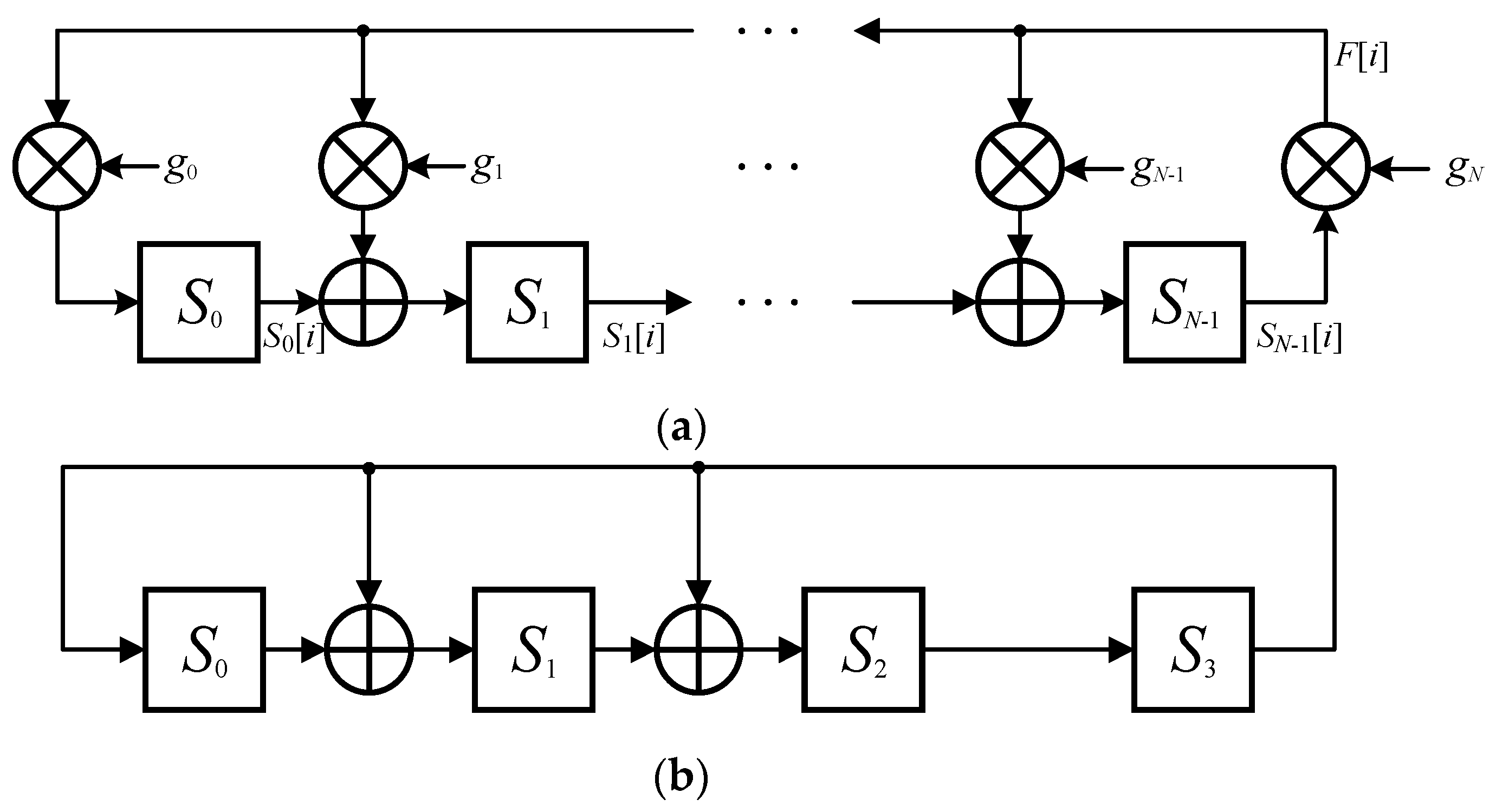
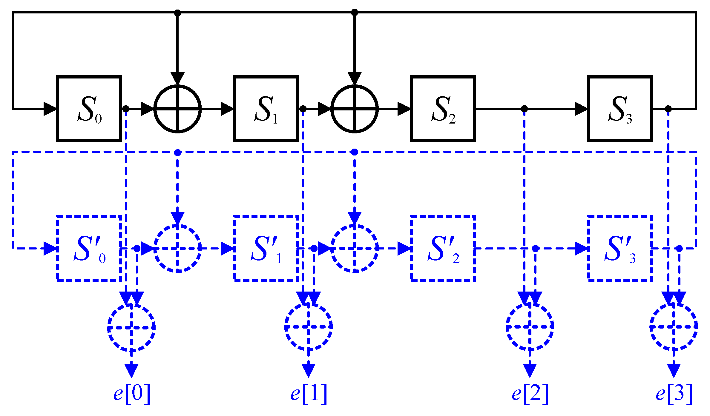
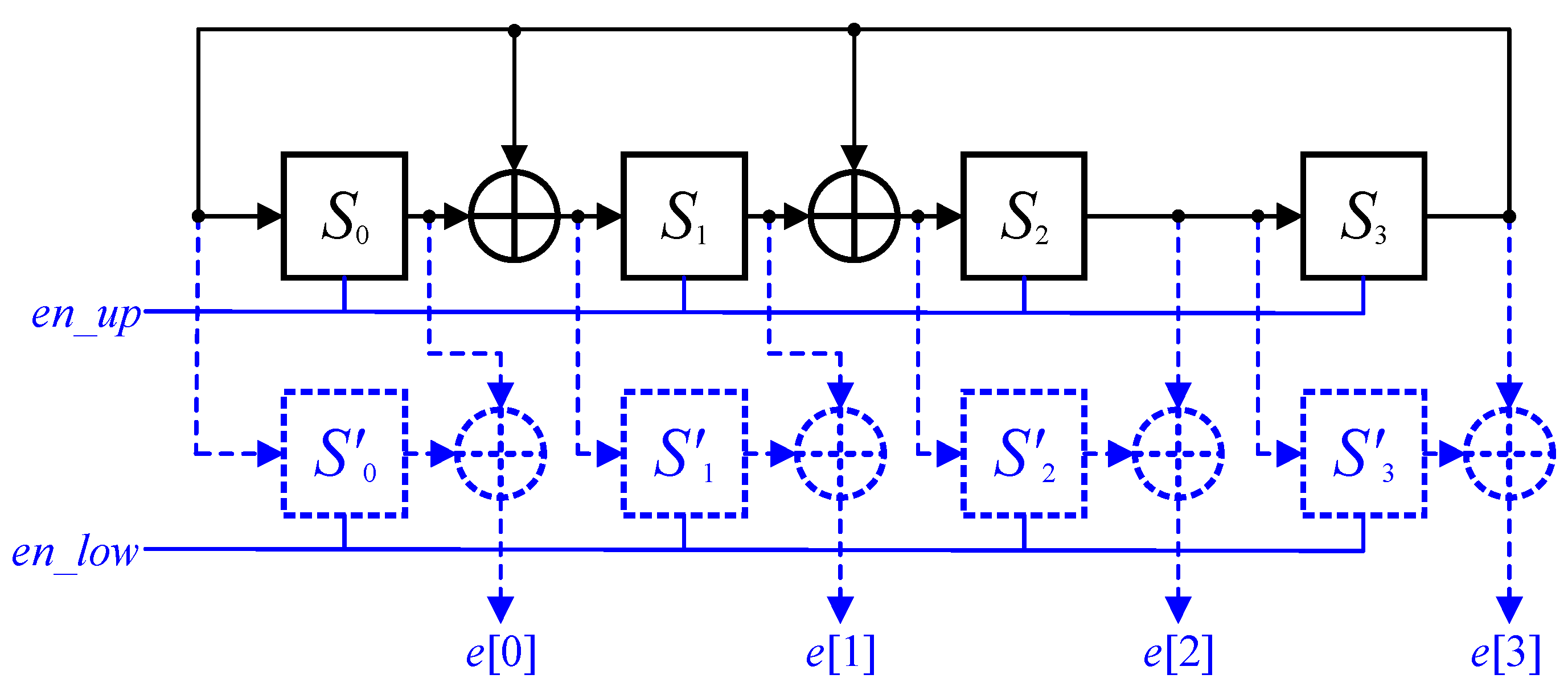
2. Existing Error Detection/Correction LFSRs
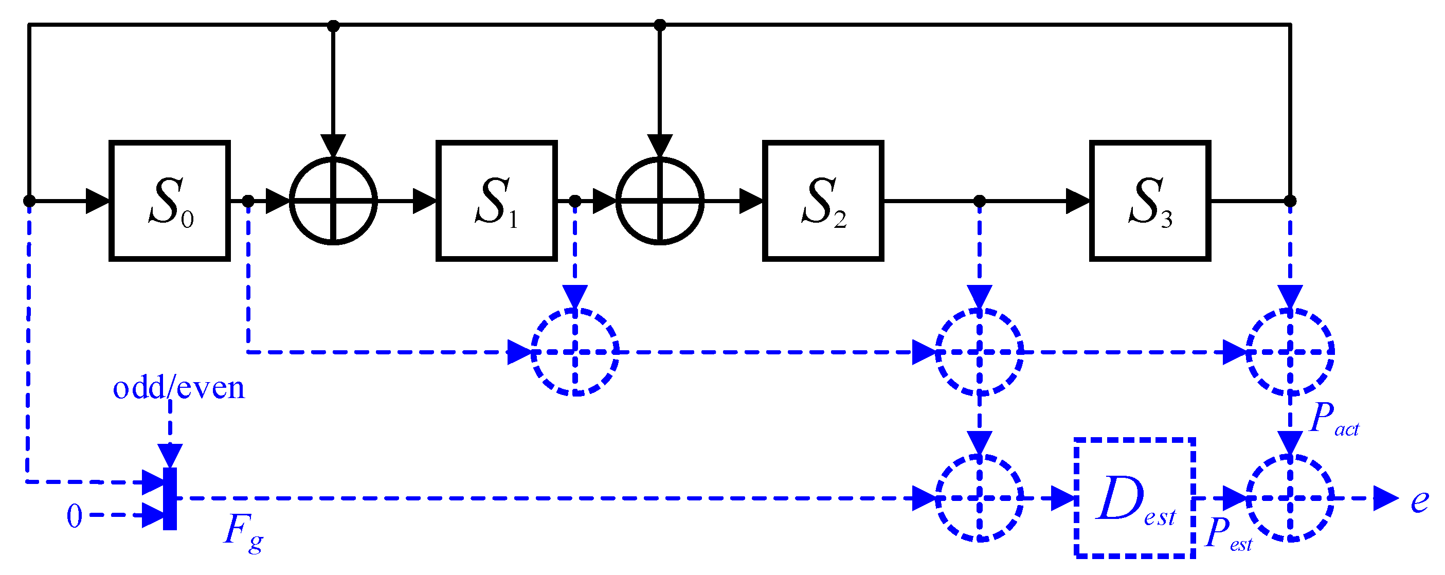
Redundancy methods are simple and efficient error detection/correction design techniques and they can be traditionally categorized into hardware and time redundancy methods [28,29,30,31,32]. Hardware redundancy [28,29,30] can be accomplished by adding copies of the original design to protect the design against malicious faults. For instance, dual modular redundancy (DMR) duplicates the original design to detect the failure of one of two copies and triple modular redundancy (TMR) triplicates the original design to correct an incorrect output, according to majority voting. In general, hardware redundancy [28,29,30] has only negligible effects on the overall system performance but incurs significant hardware overheads to maintain the desired level of reliability. Time redundancy [31,32] employs redundancy in terms of time instead of hardware and the same operation is executed multiple times with the same hardware resource. This approach detects or corrects faults by comparing all the results obtained at different times. For instance, two-time-redundancy, which is similar to DMR, allows the failure detection in one of two execution times and three-time-redundancy, which is similar to TMR allows the correction of an incorrect output according to majority voting. Unlike hardware redundancy [28,29,30], time redundancy [31,32] involves an affordable hardware overhead but incurs a performance penalty. Examples of hardware [28,29,30] and time [31,32] redundancy methods to detect undesirable faults are shown in Figure 2 and Figure 3, respectively. In both figures, the black line corresponds to the conventional LFSR [10,11,12,13,14,15,16,17,18,19,20,21] and the dashed blue line indicates the additional hardware overhead.
As shown in Figure 2, hardware redundancy [28,29,30] is simply realized by duplicating the conventional LFSR [10,11,12,13,14,15,16,17,18,19,20,21] shown in Figure 1 to operate with the same functionality in parallel. Accordingly, this approach requires more than twice hardware resources compared to the conventional LFSR [10,11,12,13,14,15,16,17,18,19,20,21]. In contrast, as shown in Figure 3, the time redundancy [31,32] approach computes the same functionality using the same hardware resources in series, although additional registers are necessary to store and compare the outputs obtained at different times. The outputs of the first computation are stored in the lower registers activated by en_low and those from the second computation are stored in the upper registers activated by en_up alternately. Although the time redundancy technique [31,32] improves the reliability, it demands a latency that is two times longer than that of the conventional LFSR [10,11,12,13,14,15,16,17,18,19,20,21]. These examples indicate that the overheads resulting from the redundancy methods [28,29,30,31,32] are as high as those of the conventional LFSR [10,11,12,13,14,15,16,17,18,19,20,21] and the overhead becomes more severe when the length N of the generator polynomial G(x) is large. Recently, more advanced redundancy technique is introduced targeting for error detection/correction adders [33,34,35], which achieves error detection/correction using information redundancy. Information redundancy saves hardware resources but demands additional computation overhead. As far as we know, there is no such information redundancy approach for an error detection LFSR structure.

3. Proposed ED-LFSR

To overcome the limitations of the existing redundancy methods, we propose a new error detection LFSR, which can detect errors with a small hardware overhead by employing the parity check technique [25,26,27]. The proposed error detection lFSR (ED-LFSR) estimates the parity of the next state by using the linear operation of the LFSRs. At the next clock cycle, the actual parity is generated and compared with the estimated one to detect the occurrence of errors. For further mathematical explanation, we adopt the parity function P(S), where P(S) = 0 and P(S) = 1 indicate even and odd parities, respectively. It can be noted that the parity function contains a linear property as it satisfies the additivity P(S0 + S1) = P(S0) + P(S1) and homogeneity P(cS) = cP(S) conditions.
The proposed ED-LFSR expects the estimation of the next parity at the i-th clock cycle by applying the parity function to the right-hand-side of (1) for 0 ≤ n < N as
P est [ i ] = P ( n = 0 N 1 ( S n 1 [ i ] + g n F [ i ] ) ) .
Although (2) can be directly used to implement an error detection LFSR, it is necessary to simplify (2) to reduce the hardware complexity. Using the additive and homogeneity properties of the parity function, (2) can be expressed as
P est [ i ] = P ( n = 0 N 1 S n 1 [ i ] ) + P ( n = 0 N 1 g n F [ i ] ) = P ( n = 0 N 1 S n 1 [ i ] ) + F [ i ] P ( n = 0 N 1 g n ) .
The last term of (3) can be implemented using a single variable as either F[i] or zero. When the parity of the generator polynomial is even, P ( n = 0 N g n ) = 0 , the last term of (3) becomes F[i] since P ( n = 0 N 1 g n ) = 1 due to the fact that the most significant coefficient gn is always one in the generator polynomial G(x). Otherwise, when the parity of the generator polynomial is odd, P ( n = 0 N g n ) = 1 , the last term of (3) becomes zero since P ( n = 0 N 1 g n ) = 0 , which becomes independent of the feedback F[i]. In other words, (2) requires 2N − 1 binary additions and (3) requires N binary additions and 1 selection. Note that the initial S−1[i] is assumed to be zero because no corresponding shift register exists.
Furthermore, the actual parity at the (i + 1)-th clock cycle is obtained by applying the parity function to the left-hand-side of (1) for 0 ≤ n < N as
P act [ i + 1 ] = P ( n = 0 N 1 S n [ i + 1 ] ) ,
where N − 1 binary additions are required. The proposed ED-LFSR compares the estimated parity Pest [i] computed at the i-th clock cycle using (3) and the actual parity Pact[i + 1] determined at the (i + 1)-th clock cycle using (4) to detect faults. Because the conventional LFSR updates the state linearly, the parity function is seamlessly applicable to the LFSR and the simple comparison allows error detection at every clock cycle.
Figure 4 shows the proposed ED-LFSR based on (3) and (4). The proposed ED-LFSR requires additional circuitry to perform the operations related to Pest and Pact. At the i-th clock cycle, the proposed ED-LFSR estimates Pest for the next clock cycle and stores it in the additional register Dest. The left-sided MUX shown in Figure 4 selectively adds either the feedback or no feedback based on the parity of the generator polynomial G(x). At the next (i + 1)-th clock cycle, the proposed ED-LFSR computes Pact and compares it with the previously estimated Pest to detect malicious faults. It can be noted that the XORs to perform the binary additions for (3) and (4) are shared to save hardware resources. While (3) is implemented to estimate the parity of the next state by using the XORs, (4) is implemented to compute and compare the parity of the current state by using a part of the same XORs. Thus, the estimation and comparison of the parities occur simultaneously at each clock cycle. Without loss of generality, the black and dashed blue lines in Figure 4 represent the conventional LFSR and additional hardware overhead, respectively. Unlike the traditional redundancy methods that require a large amount of hardware overheads, the proposed ED-LFSR incurs a small hardware overhead owing to the use of the parity check technique [25,26,27]. The parity function enables the use of only one additional register rather than N registers, as shown in Figure 2 and Figure 3. Moreover, we can further eliminate the selective MUX from the implementation point of view, as the generator polynomial is normally determined before the design stage. According to the parity of the determined generator polynomial, hard-wiring is applicable to the proposed ED-LFSR. As a result, the proposed ED-LFSR can provide the fault-detection functionality to the conventional LFSR with only a minor increase in the hardware.
Figure 5 shows the operation of the proposed ED-LFSR in detail, where even generator polynomial x4 + x2 + x + 1 and odd generator polynomial x4 + x + 1 are exemplified. Fg indicates the output of the left-sided MUX representing the last term of (3) and S0, S1, S2 and S3 represent the output from the registers shown in Figure 4. Although both even and odd polynomials generate the actual parity Pact in the same way by XORing all the register outputs based on (4), the estimated parity Pest is determined in a different way according to the parity of the generator polynomial based on (3). When the generator polynomial G(x) is even, Fg is selected as F[i] leading from S3 as shown in Figure 5a. Otherwise, Fg is selected as zero as shown in Figure 5b. According to Figure 5, we can find that the estimated parity Pest[i] always have the same pairty as the actural parity Pact[i + 1] at the (i + 1)-th clock cycle. Therefore, the proposed ED-LFSR allows error detection at every clock cycle by comparing the estimated parity and actual parity.
In general, practical LFSR applications including error-correction codes, encryption algorithms and pseudo-random number generation adopt a high number of parallel factor to provide a high system throughput, so that it is important whether the proposed method can be applied to a parallel structure with any number of parallel factor. Among various parallel structures, the simplest LFSR structure can be obtained by concatenating the XOR network as many as the number of parallel factor [14,15]. Figure 6 shows that the proposed method can be applied seamlessly to the parallel LFSR structure. Without loss of generality, the black and dashed blue lines represent the conventional parallel LFSR and additional hardware overhead, respectively. According to Figure 4 and Figure 6, the extra hardware circuitry is independent of the number of parallel factor. Therefore, the proposed method can be widely used to realize error detection with a small hardware overhead for various applications.

4. Experimental Results

For a fair comparison, we implemented various LFSRs including the conventional LFSR (Figure 1a), LFSRs with hardware [28,29,30] (Figure 2) and time redundancies [31,32] (Figure 3) and the proposed ED-LFSR (Figure 4) by using 180-nm CMOS technology with the typical case of 1.8 Voltage and 25 Celsius degree. Table 1 presents the equivalent gate counts of the error detection methods for generator polynomials of different lengths synthesized with an operating frequency of 200 MHz. Note that the equivalent gate count is calculated by dividing the total design area by the 2-input NAND gate for a fair complexity comparison. Because the traditional redundancy methods [28,29,30,31,32] require overheads that are as high as those of the conventional LFSR [10,11,12,13,14,15,16,17,18,19,20,21], the total hardware complexity for the hardware and time redundancy LFSRs [28,29,30,31,32] is almost two times that of the conventional LFSR [10,11,12,13,14,15,16,17,18,19,20,21] regardless of the length of the generator polynomial. Although the time redundancy technique [31,32] exhibits a complexity slightly less than that of the hardware redundancy approach [28,29,30], the system throughput is degraded by 50% to perform the same operation two times. Unlike the traditional redundancy methods [28,29,30,31,32] whose complexities are approximately two times that of the conventional LFSR, the proposed ED-LFSR considerably reduces the hardware resources by employing the linear property of the parity check function according to (3) and (4). For a length of 64, the proposed ED-LFSR requires an additional hardware of only 31.1% compared to that required by the original LFSR [10,11,12,13,14,15,16,17,18,19,20,21] and it saves 39.1% and 31.9% of the resources compared to the corresponding utilization of the hardware and time redundancy methods [28,29,30,31,32].
To bring a practical analysis, Table 2 compares the physical metrics for each LFSR structure with a length of 64. Synopsys Design compiler are used to measure equivalent gate count, area and critical-path delay and Synopsys Power compiler are used to estimate power consumption with 180-nm CMOS technology. Compared to the conventional LFSR, ED-LFSRs including hardware redundancy, time redundancy and proposed ones inevitably increases equivalent gate count, area, power consumption, critical-path delay and decreases throughput due to additional detection circuits. Although the proposed ED-LFSR requires slightly longer critical-path delay and lower throughput, the proposed ED-LFSR improves equivalent gate count, area and power consumption significantly compared to the previous hardware and time redundancies. Note that the throughputs for the conventional, hardware redundancy, proposed are obtained by taking the inverse of the clock period or critical-path delay since one clock cycle is necessary to operate one bit shift or operation. However, the throughput for the time redundancy is obtained by taking a half of the inverse of the clock period or critical-path delay. The previous time redundancy needs two clock cycles to operate one bit shift since the time redundancy computes the same operation twice to detect an error using the same hardware. As a result, the proposed ED-LFSR outperforms the previous ED-LFSRs for the normalized performance metrics while allowing error detection capability to the conventional LFSR structure.
Table 3 presents the hardware resources required by the various LFSRs in terms of the length N and weight G of a generator polynomial. In all cases, the proposed ED-LFSR requires the smallest overheads to improve the reliability and availability of the conventional LFSRs [10,11,12,13,14,15,16,17,18,19,20,21] regardless of the considered generator polynomial.
In addition, Missed Detection Rate (MDR) is calculated for more accurate performance measurement of the proposed ED-LFSR. Due to the nature of the 1-bit parity code, the proposed ED-LFSR is able to detect the odd number of errors completely but not the even number of errors. Accordingly, MDR of the n-bit ED-LFSR with respect to the probability of error occurrence p is obtained as
M D R = k = 1 n / 2 n C 2 k p 2 k ( 1 p ) n 2 k .
Figure 7 shows theoretical and experimental results for various lengths of LFSR with different error occurrence p ranging from 10−1 to 10−4. The theoretical results obtained from (5) are shown as lines and the experimental results obtained from simulations are indicated as markers. According to Figure 7, the experimental results are exactly fit in the theoretical results.

5. Conclusions

We proposed a new error detection linear feedback shift register that can detect the undesirable errors with only a small hardware overhead by employing the parity check technique [25,26,27]. The parity function is applied to the conventional LFSR [10,11,12,13,14,15,16,17,18,19,20,21] and later simplified using the linear property of the parity function. The proposed structure is carefully designed to reduce hardware complexity by sharing a part of the circuitries. The experimental results indicate that the proposed ED-LFSR always maintains the smallest hardware complexity among all the error detection LFSR designs, regardless of the employed generator polynomials. Thus, the proposed method can provide an area-efficient solution to incorporate the error detection technique in the conventional LFSRs [10,11,12,13,14,15,16,17,18,19,20,21]. The further work includes the complete error detection and the error-correction methods for LFSRs since the proposed method can support only the odd numbers of error detection due to the property of the parity check.

Author Contributions

Conceptualization, B.Y.K.; Data curation, H.S.; Formal analysis, B.Y.K.; Funding acquisition, H.Y.; Investigation, S.C. and J.P.; Methodology, H.S.; Project administration, H.Y.; Resources, H.S.; Software, J.P.; Supervision, H.Y.; Validation, S.C.; Visualization, H.S.; Writing—Original draft, H.S.; Writing—Review & editing, H.Y. All authors have read and agreed to the published version of the manuscript.

Funding

This research received no external funding.

Acknowledgments

This work was supported by the National Research Foundation of Korea (NRF) grant funded by the Korea government (MSIT) (NRF-2019M3F3A1A01074449) and EDA tools were supported by IDEC, Korea.

Conflicts of Interest

The authors declare no conflict of interest.

References

  1. He, Q.P.; Wang, J. Fault Detection Using the k-Nearest Neighbor Rule for Semiconductor Manufacturing Processes. IEEE Trans. Semicond. Manuf. 2007, 20, 345–354. [Google Scholar] [CrossRef]
  2. Cherry, G.A.; Qin, S.J. Multiblock principal component analysis based on a combined index for semiconductor fault detection and diagnosis. IEEE Trans. Semicond. Manuf. 2006, 19, 159–172. [Google Scholar] [CrossRef]
  3. Cangellaris, A.C.; Pinello, W.; Ruehli, A. Circuit-based description and modeling of electromagnetic noise effects in packaged low-power electronics. In Proceedings of the International Conference on Computer Design VLSI in Computers and Processors, Austin, TX, USA, 12–15 October 1997; pp. 136–142. [Google Scholar]
  4. Catt, I. Crosstalk (Noise) in Digital Systems. IEEE Trans. Electron. Comput. 1967, 16, 743–763. [Google Scholar] [CrossRef]
  5. Paul, B.C.; Roy, K. Testing cross-talk induced delay faults in static CMOS circuit through dynamic timing analysis. In Proceedings of the International Test Conference, Baltimore, MD, USA, 7–10 October 2002; pp. 384–390. [Google Scholar]
  6. O’Gorman, T.J.; Ross, J.M.; Taber, A.H.; Ziegler, J.F.; Muhlfeld, H.P.; Montrose, C.J.; Curtis, H.W.; Walsh, J.L. Field testing for cosmic ray soft errors in semiconductor memories. IBM J. Res. Dev. 1996, 40, 41–50. [Google Scholar] [CrossRef]
  7. Isermann, R.; Schwarz, R.; Stolzl, S. Fault-tolerant drive-by-wire systems. IEEE Control Syst. Mag. 2002, 22, 64–81. [Google Scholar]
  8. Baleani, M.; Ferrari, A.; Mangeruca, L.; Sangiovanni-Vincentelli, A.; Peri, M.; Pezzini, S. Fault-tolerant platforms for automotive safety-critical applications. In Proceedings of the 2003 international conference on Compilers, architectures and synthesis for embedded systems, San Jose, CA, USA, 30 October–1 November 2003; pp. 170–177. [Google Scholar]
  9. Cardarilli, G.C.; Ottavi, M.; Pontarelli, S.; Re, M.; Salsano, A. Fault tolerant solid state mass memory for space applications. IEEE Trans. Aerosp. Electron. Syst. 2005, 41, 1353–1372. [Google Scholar] [CrossRef]
  10. Cheng, C.; Parhi, K.K. High speed VLSI architecture for general linear feedback shift register (LFSR) structures. In Proceedings of the 2009 Conference Record of the Forty-Third Asilomar Conference on Signals, Systems and Computers, Pacific Grove, CA, USA, 1–4 November 2009; pp. 713–717. [Google Scholar]
  11. Aloisi, W.; Mita, R. Gated-Clock Design of Linear-Feedback Shift Registers. IEEE Trans. Circuits Syst. Π Express Briefs 2008, 55, 546–550. [Google Scholar] [CrossRef]
  12. Wang, L.-T.; McCluskey, E.J. Linear feedback shift register design using cyclic codes. IEEE Trans. Comput. 1988, 37, 1302–1306. [Google Scholar] [CrossRef]
  13. Bagalkoti, A.; Shirol, S.B.; Ramakrishna, S.; Kumar, P.; Rajashekar, B.S. Design and Implementation of 8-bit LFSR, Bit-Swapping LFSR and Weighted Random Test Pattern Generator: A Performance Improvement. In Proceedings of the 2019 International Conference on Intelligent Sustainable Systems (ICISS), Palladam, Tamilnadu, India, 21–22 February 2019; pp. 82–86. [Google Scholar]
  14. Sprachmann, M. Automatic generation of parallel CRC circuits. IEEE Des. Test Comput. 2001, 18, 108–114. [Google Scholar] [CrossRef]
  15. Jung, J.; Yoo, H.; Lee, Y.; Park, I.C. Efficient Parallel Architecture for Linear Feedback Shift Registers. IEEE Trans. Circuits Syst. Π Express Briefs 2015, 62, 1068–1072. [Google Scholar] [CrossRef]
  16. Ayinala, M.; Parhi, K.K. Efficient parallel VLSI architecture for linear feedback shift registers. 2010 IEEE Workshop Signal Process. Syst. 2010, 52–57. [Google Scholar]
  17. Ayinala, M.; Parhi, K.K. High-Speed Parallel Architectures for Linear Feedback Shift Registers. IEEE Trans. Signal Process. 2011, 59, 4459–4469. [Google Scholar] [CrossRef]
  18. Lowy, M. Parallel implementation of linear feedback shift registers for low power applications. IEEE Trans. Circuits Syst. Π Analog Digit. Signal Process. 1996, 43, 458–466. [Google Scholar] [CrossRef]
  19. Zhang, X. A Low-Power Parallel Architecture for Linear Feedback Shift Registers. IEEE Trans. Circuits Syst. Π Express Briefs 2019, 66, 412–416. [Google Scholar] [CrossRef]
  20. Katti, R.S.; Ruan, X.; Khattri, H. Multiple-output low-power linear feedback shift register design. IEEE Trans. Circuits Syst. I Regul. Pap. 2006, 53, 1487–1495. [Google Scholar] [CrossRef] [Green Version]
  21. Kumar, G.S.; Saminadan, V. Low Power LFSR for BIST Applications. In Proceedings of the 2018 Second International Conference on Intelligent Computing and Control Systems (ICICCS), Madurai, India, 14–15 June 2018; pp. 1979–1984. [Google Scholar]
  22. Abu-Issa, A.S.; Quigeley, S.F. Bit-swapping LFSR for low-power BIST. Electron. Lett. 2008, 44, 401–403. [Google Scholar] [CrossRef]
  23. Nourani, M.; Tehranipoor, M.; Ahmed, N. Low-Transition Test Pattern Generation for BIST-Based Applications. IEEE Trans. Comput. 2008, 57, 303–315. [Google Scholar] [CrossRef]
  24. Kitsos, P.; Sklavos, N.; Zervas, N.; Koufopavlou, O. A reconfigurable linear feedback shift register (LFSR) for the Bluetooth system. In Proceedings of the 8th IEEE International Conference on Electronics, Circuits and Systems, Malta, Malta, 2–5 September 2001; pp. 991–994. [Google Scholar]
  25. Lin, S.; Costello, D.J. Error Control Coding, 2nd ed.; Pearson India: Englewood Cliffs, NJ, USA, 2004; pp. 92–94. [Google Scholar]
  26. Mohanram, K.; Sogomonyan, E.S.; Gossel, M.; Touba, N.A. Synthesis of low-cost parity-based partially self-checking circuits. In Proceedings of the 9th IEEE On-Line Testing Symposium, Kos Island, Greece, 7–9 July 2003; pp. 35–40. [Google Scholar]
  27. Kubalik, P.; Fiser, P.; Kubatova, H. Fault tolerant system design method based on self-checking circuits. In Proceedings of the 12th IEEE International On-Line Testing Symposium, Lake Como, Italy, 10–12 July 2006. [Google Scholar]
  28. Johnson, B.W.; Aylor, J.H.; Hana, H.H. Efficient Use of Time and Hardware Redundancy for Concurrent Error Detection in a 32-bit VLSI Adder. IEEE J. Solid State Circuits 1988, 23, 208–215. [Google Scholar] [CrossRef]
  29. Fuhrman, C.P.; Chutani, S.; Nussbaumer, H.J. Hardware/software fault tolerance with multiple task modular redundancy. In Proceedings of the IEEE Symposium on Computers and Communications, Alexandria, Egypt, 27–29 July 1995; pp. 171–177. [Google Scholar]
  30. She, X.; McElvain, K.S. Time Multiplexed Triple Modular Redundancy for Single Event Upset Mitigation. IEEE Trans. Nucl. Sci. 2009, 56, 2443–2448. [Google Scholar] [CrossRef]
  31. Antola, A.; Negrini, R.; Sami, M.G.; Scarabottolo, N. Fault Tolerance in FFT Arrays: Time Redundancy Approaches. J. Vlsi Signal Process. 1992, 4, 295–316. [Google Scholar] [CrossRef]
  32. Nicolaidis, M. Time redundancy based soft-error tolerance to rescue nanometer technologies. In Proceedings of the 17th IEEE VLSI Test Symposium, Dana Point, CA, USA, 25–29 April 1999; pp. 86–94. [Google Scholar]
  33. Bin Talib, G.H.; El-Maleh, A.H.; Sait, S.M. Design of Fault Tolerant Adders: A Review. Arab. J. Sci. Eng. 2018, 43, 6667–6692. [Google Scholar] [CrossRef]
  34. Valinataj, M.; Mirshekar, M.; Jazayeri, H. Novel low-cost and fault-tolerant reversible logic adders. Comput. Electr. Eng. 2016, 53, 56–72. [Google Scholar] [CrossRef]
  35. Babu, H.H.; Jamal, L.; Saleheen, N. An efficient approach for designing a reversible fault tolerant n-bit carry look-ahead adder. In Proceedings of the 2013 IEEE International SOC Conference, Erlangen, Germany, 4–6 September 2013; pp. 98–103. [Google Scholar]
Figure 1. Conventional linear feedback shift register (LFSR). (a) General linear feedback shift register; (b) Example of LFSR associated with G(x) = x4 + x2 + x + 1.
Electronics 09 00195 g001
Figure 2. Example of hardware redundancy method [28,29,30].
Electronics 09 00195 g002
Figure 3. Example of time redundancy method [31,32].
Electronics 09 00195 g003
Figure 4. Structure of the proposed FT-LFSR.
Electronics 09 00195 g004
Figure 5. Proposed error detection LFSR (ED-LFSR) operation at (a) even generator polynomial x4 + x2 + x + 1; (b) odd generator polynomial x4 + x + 1.
Electronics 09 00195 g005
Figure 6. Structure of the proposed LFSR with a parallel factor of 4.
Electronics 09 00195 g006
Figure 7. Missed Detection Rates for the proposed FT-LFSR.
Electronics 09 00195 g007
Table 1. Equivalent gate counts for various LFSR designs.
ConventionalHardware RedundancyTime RedundancyProposed
8-bit107.1224.9203.6134.1
16-bit202.9431.2387.3251.2
32-bit399.9847.2769.3497.1
64-bit780.31653.41502.51023.1
Table 2. Physical metrics for various LFSR designs with a length of 64.
Physical MetricsConventionalHardware RedundancyTime RedundancyProposed
Area [A]7786.99 μm216,499.19 μm214,994.06 μm210,209.15 μm2
Equivalent Gate Count780.341653.431502.521023.14
Power Consumption [B]0.71 mW1.26 mW1.49 mW0.84 mW
Critical-Path Delay3.74 ns3.90 ns3.74 ns3.99 ns
Throughput [C]267.37 Mbps256.41 Mbps133.69 Mbps250.63 Mbps
Normalized Metric [D] *1.000.260.130.60
* [D] = [C]/([A] × [B]) Mbps/(μm2 × mW).
Table 3. Summary of hardware complexities.
ConventionalHardware RedundancyTime RedundancyProposed
RegisterN2N2NN + 1
XORG2G + NG + NG + N + 1
MUX---1

