Article

Two-Source Asymmetric Turbo-Coded Cooperative Spatial Modulation Scheme with Code Matched Interleaver

College of Electronic and Information Engineering, Nanjing University of Aeronautics and Astronautics, Nanjing 210016, China
*
Author to whom correspondence should be addressed.
Electronics 2020, 9(1), 169; https://doi.org/10.3390/electronics9010169
Submission received: 17 December 2019 / Revised: 10 January 2020 / Accepted: 12 January 2020 / Published: 16 January 2020
(This article belongs to the Section Microwave and Wireless Communications)

Abstract

:
This paper proposes, for the first time, a two-source asymmetric turbo-coded-cooperative spatial modulation (SM) scheme over the slow Rayleigh fading channel. As in any coded cooperative communication, the interleaver plays a vital role in mitigating the harsh effect of the wireless channel. Therefore, the code matched interleaver (CMI) is effectively used in the proposed design. The simulated results reveal that the bit error rate (BER) performance of the proposed coded cooperative communication system outperforms the asymmetric turbo-coded non-cooperative scheme under identical conditions. This prominent performance improvement has been made possible due to the joint asymmetric turbo decoding at the destination node. Furthermore, to check the effectiveness of the proposed scheme, we have also developed a two-source asymmetric turbo-coded cooperative scheme based on the vertical bell labs layered space-time (VBLAST), incorporating the CMI as the suitable benchmark. It is observed that the proposed scheme employing SM has a better BER performance than the VBLAST scheme under identical conditions.

1. Introduction

Recently, there has been a rapid increase in the demand for high data rates in modern wireless communications [1]. Nevertheless, an inevitable fading phenomenon severely affects the bit error rate (BER) performance of wireless communication systems [2]. A multiple-input multiple-output (MIMO) technique has been adopted as a useful solution to combat the effect of the fading channel, since it has the potential to increase the data rate and to improve the BER performance of the wireless link [3]. However, small handheld wireless devices may not be capable of supporting multiple antennas due to size, cost, or hardware limitations [4]. The cooperative communication suggested in [5,6] enables one to address these drawbacks by creating a virtual MIMO. Cooperative techniques can also be merged with channel codes to achieve coded cooperative diversity. Different channel coding schemes such as convolution codes [7], turbo codes [8], low density parity check (LDPC) codes [9], and polar codes [10] have been utilized in coded cooperative communication. Furthermore, cooperative techniques can be used in cellular communications [11,12,13].
Spatial modulation (SM) [14] is a recently developed MIMO technique that boosts spectral efficiency by utilizing antenna indices to convey information. In SM, only one transmit antenna is active at each time slot. Therefore, drawbacks, such as inter-channel interference (ICI) and inter-antenna synchronization (IAS), are alleviated. Furthermore, as compared to existing vertical bell labs layered space-time (VBLAST) architecture [14,15,16,17], SM significantly increases BER performance and decreases the transceiver complexity [14]. In [18], an optimal hard maximum likelihood detection (MLD) for SM was discussed. Furthermore, the soft output MLD for SM was proposed in [19]. There are many achievements related to SM when combined with channel codes. In [20], an LDPC-coded SM scheme was proposed and investigated. In [21], it was proven that the integration of polar codes and SM can offer a superior performance. Later, the authors in [22] discussed and studied a polar-coded SM with multiple antennas at a transceiver in which the multi-level construction of polar codes was employed.
Turbo codes were firstly introduced in 1993 [23]. Since then, they have attracted much attention from many scholars. The performance of a turbo code is based on its distance spectrum. A good interleaver plays an important role in shaping the weight distribution that eventually controls the performance of communication systems [24]. Hence, the interleaver is regarded as a vital part in the design of turbo codes. To date, many researchers have designed different types of interleavers [25,26,27,28,29] for the turbo code. In [28], it was well proven that the code matched interleaver (CMI) is the optimum interleaver of turbo codes. In [30], the authors analyzed and discussed the BER performance of asymmetric turbo codes with the CMI. To the best of our knowledge, asymmetric turbo coded SM (ATC-SM) as an integration of asymmetric turbo codes based on the CMI and SM with higher-order modulation in non-cooperative scenarios, has not been investigated. Therefore, the exploration of ATC-SM is still an open research problem. In order to make full use of the benefits of coded cooperation techniques, we further extend ATC-SM to a coded cooperative scenario, i.e., asymmetric turbo-coded cooperative SM (ATCC-SM). In the ATCC-SM scheme, two sources work in full duplex mode. The contributions of this manuscript can precisely be written as:
  • An asymmetric turbo-coded SM (ATC-SM) technique is proposed. The proposed scheme adopts a higher order modulation such as 16QAM, 32QAM and 64QAM.
  • The proposed scheme is further extended to coded-cooperative scenarios with two sources, such as the asymmetric turbo-coded cooperative SM (ATCC-SM) technique.
  • The asymmetric turbo-coded vertical bell labs layered space-time (ATC-VBLAST) is also devised as an appropriate benchmark for the proposed ATC-SM scheme. Similarly, the asymmetric turbo-coded cooperative vertical bell labs layered space-time (ATCC-VBLAST) scheme is utilized as a suitable benchmark for ATCC-SM under identical conditions.
  • A joint iterative ATC decoder for two sources is also implemented at the destination node.
The rest of this manuscript is organized as follows. Section 2 introduces the fundamental construction of the ATC with the CMI and proposes two non-cooperative schemes, i.e., ATC-SM and ATC-VBLAST. Section 3 discusses the system model for two coded-cooperative schemes, i.e., ATCC-SM and ATCC-VBLAST. Section 4 demonstrates the joint iterative ATC decoder. The results and discussion are presented in Section 5. Finally, Section 6 draws the conclusion of this manuscript.

2. Asymmetric Turbo Code (ATC)

The ATC encoder is composed of an interleaver π , and two different recursive systematic convolutional (RSC) encoders, B 1 and B 2 , as shown in Figure 1. The g a ( F ) / g b ( F ) represents the generator polynomial of RSC encoder, where g a ( F ) and g b ( F ) denote the feed-forward and feedback encoding polynomials, respectively.
The input information sequence q 1 and interleaved sequence q 1 I are encoded by B 1 and B 2 into parity sequences p 1 and p 2 , respectively. Then, these sequences are combined with the input sequence q 1 to generate the entire ATC codeword ( q 1 ,   p 1 ,   p 2 ) .

2.1. Code Matched Interleaver

The quality of a code depends on its distance spectrum properties. Choosing a good interleaver contributes to the excellent distance characteristics of an ATC. In [28], it was proven that the CMI fully removes low weight sequences as compared to other types of interleavers to boost the properties of a distance spectrum. Therefore, the CMI is regarded as an optimal interleaver. Furthermore, the CMI is, first, an S-random interleaver. The S-random interleaver can either eliminate a short weight-3 input sequence with lengths up to S + 1 or expand it to another sequence with lengths greater than 2(S + 1) [31]. Therefore, we primarily focused on weight-2 and weight-4 sequences in the design of the CMI. We discuss the construction of the CMI for the ATC in the following section.
The input sequence q 1 is encoded by the ATC encoder into codeword ( q 1 ,   p 1 ,   p 2 ) . The weights of information and parity bit sequences are denoted by β , β ( p 1 ) and β ( p 2 ) , respectively. The overall weight of ATC codeword is expressed as:
w = β + β ( p 1 ) + β ( p 2 ) ,
Assume that weight β = 2 input sequence q 1 , 2 produces a finite weight ATC codeword; then, the input sequence q 1 , 2 and permuted sequence q 1 , 2 I can be represented by the following polynomials:
q 1 , 2 ( F ) = ( 1 + F ε 1 c 1 ) F γ 1 , q 1 , 2 I ( F ) = ( 1 + F ε 2 c 2 ) F γ 2 ,
where c 1 ,   c 2 = 1 ,   2 , , ε 1 and ε 2 denote the minimum distances between two consecutive “1”s of the q 1 , 2 and q 1 , 2 I , respectively, and γ 1 and γ 2 represent time delays, γ 1 , γ 2 = 1 ,   2 , The weights of parity bits given in Equation (2) can be written as:
c 1 ( l min , 1 2   ) + 2 ,   c 2 ( l min , 2 2 ) + 2 ,
where l min , 1 and l min , 2 represent the lowest weights of parity check sequences p 1 and p 2 generated by the sequences q 1 , 2 and q 1 , 2 I , respectively. By combining Equations (1) and (3), the overall weight of the ATC codeword produced by the weight-2 input sequence q 1 , 2 can be given as:
  w β = 2 = 6 + c 1 ( l min , 1   2 ) + c 2 ( l min , 2 2 )
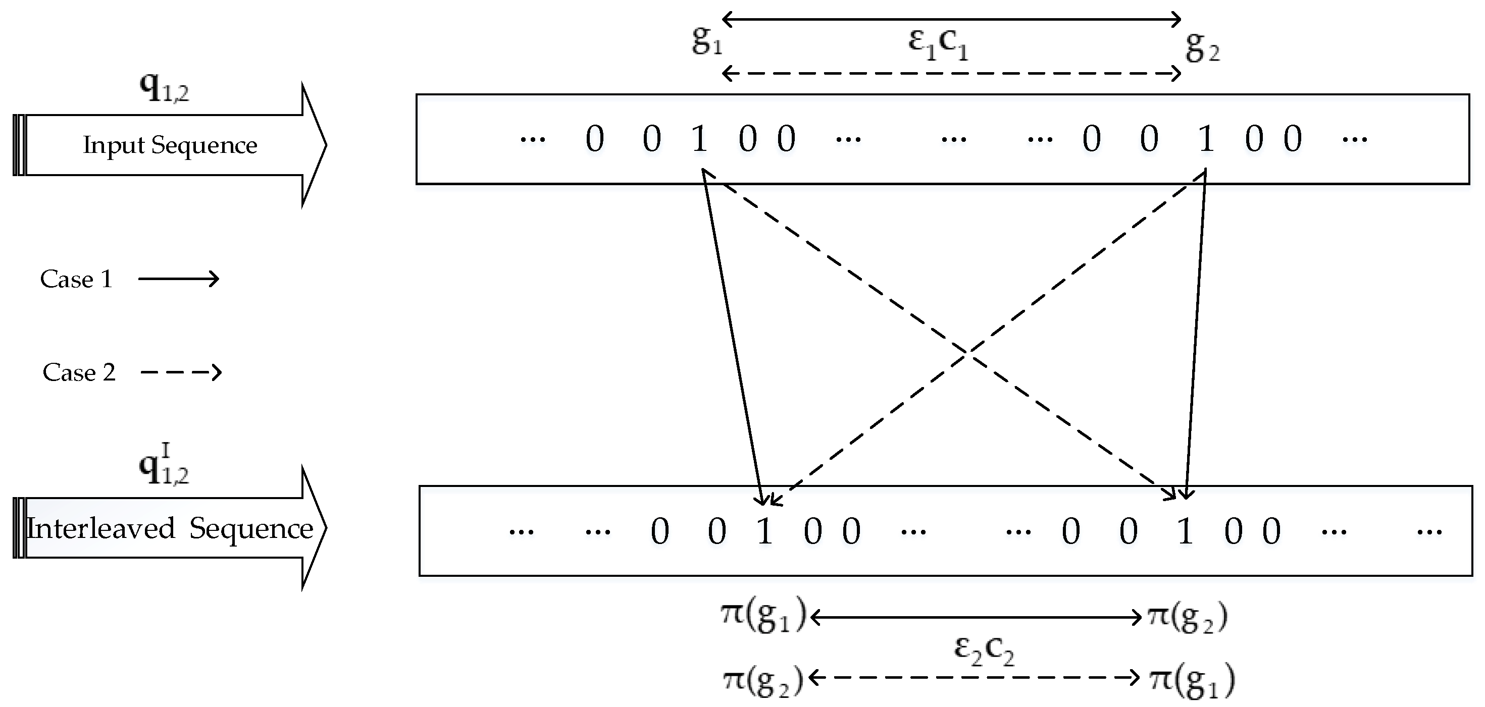
Let g 1 and g 2 represent the positions of “1”s in the input sequence q 1 , 2 . The positions of “1”s in the interleaved sequence q 1 , 2 I are denoted by π ( g 1 ) and π ( g 2 ) . If the mapping condition satisfies the following form:
| g 1 g 2 |   mod   ε 1 =   0   and   | π ( g 1 ) π ( g 2 ) |   mod   ε 2 =   0 ,
The interleaver maps the input sequence q 1 , 2 to the interleaved sequence q 1 , 2 I that produces a finite weight parity check sequence, as shown in Figure 2. Note that this case is detrimental because both q 1 , 2 and q 1 , 2 I generate finite weight parity check sequences to cause a degradation in system performance. To avoid this phenomenon, the mapping condition is required to meet the following expression:
| g 1 g 2 |   mod   ε 1   =   0   and   | π ( g 1 )     π ( g 2 ) |   mod   ε 2     0 ,
Now, we consider the weight-4 input sequence. The weight-4 input sequence is comprised of two weight-2 sequences. Thus, a finite weight ATC codeword is generated. The polynomials of weight β = 4 input sequence q 1 , 4 and permuted sequence q 1 , 4 I are written as:
q 1 , 4 ( F ) = ( 1 + F ε 1 c 1 ) F γ 1 + ( 1   +   F ε 1 c 2 ) F γ 2         q 1 , 4 I ( F )   = ( 1   +   F ε 2 c 3 ) F γ 3   +   ( 1   +   F ε 2 c 4 ) F γ 4 ,
where c 1 , c 2 ,   c 3 , c 4   =   1 , 2 , , γ 1 , γ 2 , γ 3 and γ 4 denote time delays such that γ 2   >   γ 1 +   ε 1 c 1 and γ 4   >   γ 3 +   ε 2 c 3 . The total weight of the ATC codeword generated by weight-4 input sequence q 1 , 4 is given as:
w β = 4 = 12 + ( c 1   +   c 2 ) ( l min , 1   2 )   +   ( c 3   +   c 4 ) ( l min , 2 2 )
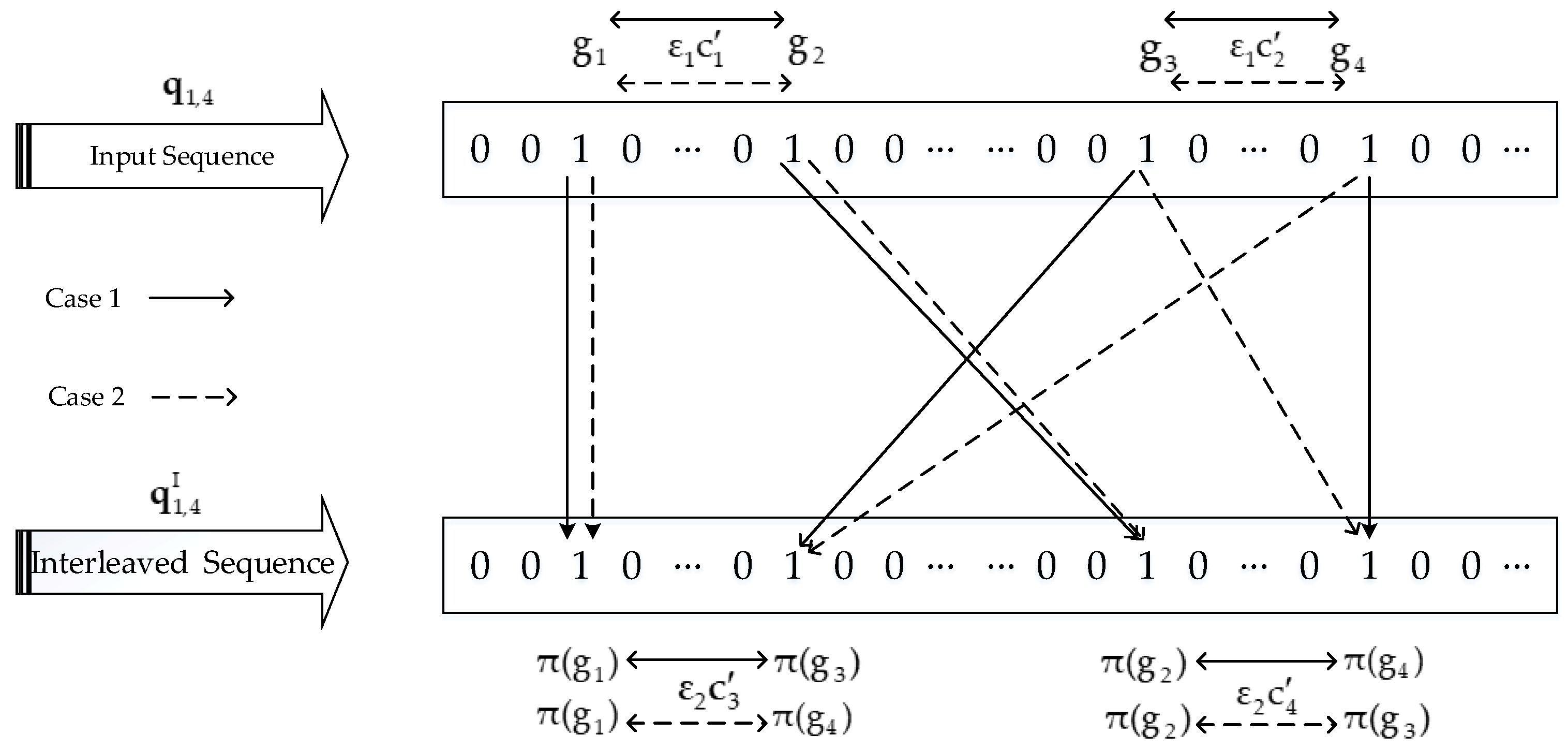
It is assumed that g 1 , g 2 , g 3 and g 4 denote the positions of “1” in the input sequence q 1 , 4 , where g 1   <   g 2 <   g 3   <   g 4 . Let π ( g 1 ) , π ( g 2 ) , π ( g 3 ) and π ( g 4 ) be the positions of “1” in the interleaved sequence q 1 , 4 I . If the mapping conditions meet the following form:
{ whenever   | g 1   g 2 |   mod   ε 1   =   0   and   | g 3   g 4 |   mod   ε 1   =   0 | π ( g 1 )     π ( g 3 ) |   mod   ε 2   =   0   and   | π ( g 2 )     π ( g 4 ) |   mod   ε 2   =   0
or
{ whenever   | g 1   g 2 |   mod   ε 1   =   0   and   | g 3   g 4 |   mod   ε 1   =   0 | π ( g 1 )     π ( g 4 ) |   mod   ε 2   =   0   and   | π ( g 2 )   π ( g 3 ) |   mod   ε 2   =   0
then the interleaver will map the input sequence q 1 , 4 into q 1 , 4 I , which produces finite weight parity check sequence, as illustrated in Figure 3. Due to the fact that both q 1 , 4 and q 1 , 4 I generate finite weight parity check sequences, the overall ATC codeword weight given by Equation (8) is finite. In order to avoid the generated scenario, the following mapping conditions should be satisfied:
{ whenever   | g 1   g 2 |   mod   ε 1   =   0   and   | g 3     g 4 |   mod   ε 1   =   0 | π ( g 1 )     π ( g 3 ) |   mod   ε 2     0   and   | π ( g 2 )     π ( g 4 ) |   mod   ε 2     0
or
{ whenever     | g 1   g 2 |   mod   ε 1   =   0   and   | g 3   g 4 |   mod   ε 1   =   0 | π ( g 1 )   π ( g 4 ) |   mod   ε 2     0   and   | π ( g 2 )     π ( g 3 ) |   mod   ε 2     0
It is worth mentioning that not all finite weight sequences are bad. Actually, only those input sequences whose weights are less than certain value w max ( β )   ( β   =   2 , 4 ) should be eliminated. The parameter w max ( β ) acts like a threshold [30]. By combining Equation (4) with w max β = 2 , and integrating Equation (8) with w max β = 4 , we obtained the following inequalities:
6   +   c 1 ( l min , 1 2 )   +   c 2 ( l min , 2 2 )     w max β = 2 ,       12   +   ( c 1   +   c 2 ) ( l min , 1 2 )   +   ( c 3   +   c 4 ) ( l min , 2 2 )     w max β = 4 ,
If l min , 1 = l min , 2 = l min , the above inequalities are equivalent to:
c 1   +   c 2     w max β = 2 6 l min 2 ,         c 1 +   c 2   +   c 3   +   c 4     w max β = 4 12 l min 2
The algorithm utilized in [28] for the interleaver design is described as follows:
  • Let us randomly choose an integer from the finite set I S   =   { 1 ,   2 ,   ,   N } , where N denotes the size of the interleaver.
  • Compare the selected integer with S previous selected integers, where S   <   N / 2 . If the absolute value of the difference between the current selected integer and any of the S previous selected integers is smaller than S [31], then go back to the first step and search for a proper integer.
  • Check whether the weight-2 and 4 mapping conditions are simultaneously satisfied by the current interleaver output. If they are not satisfied, then go back to the first step.
  • When a specified number of iterations is reached, if we do not find an integer from the set I S to make it satisfy both the second and third steps simultaneously, then the value S is reduced by 1 and the process is restarted from the first step.
  • The selected integer is saved as the current interleaver output. Repeat the process until we obtain all N interleaver outputs.

2.2. Asymmetric Turbo-Coded Spatial Modulation (ATC-SM) Scheme with CMI

The schematic of the ATC-SM scheme based on the CMI is illustrated in Figure 4. This scheme consists of N T transmit antennas and N R receive antennas.
The information bit sequence a 1 of length K is encoded into codewords v of length 3 K by an ATC encoder at the source node. The generated ATC codeword v is divided into v ( j ) with length d   = log 2 MN T by the bit grouping block shown in Figure 4, where M denotes the modulation order and j { 1 ,   2 , ,   3 K / d } . Then, v ( j ) is fed into the bit divider block. After the bit divider, the grouped bit sequence v ( j ) is further partitioned into two parts, v ( j ) ante and v ( j ) modu . The first bit train v ( j ) ante with length log 2 N T is sent to the antenna mapper to determine the active antenna index I ( j ) , where I ( j ) { 1 ,   2 , ,   N T } . Likewise, the M-PSK/QAM modulator obtains the remaining bit train v ( j ) modu of length log 2 M and modulates it into the M-PSK/QAM symbol v s ( j ) with E[|vs(j)|2] = 1, where s { 1 ,   2 , ,   M } and || represents the Euclidean norm of a vector or matrix. Subsequently, the modulated symbol v s ( j ) is assigned to the chosen active antenna index I ( j ) . Thus, the coded SM mapper outputs the vector v Is ( j )   =   [ 0 , ,   0 ,   v s ( j ) ,   0 , ,   0 ] T , where v s ( j ) represents the I ( j ) th non-zero component of the vector. Note that the components such as bit grouping, the bit divider, the antenna mapper, the M-PSK/QAM modulator and the coded SM mapper together constitute the main block called SM in this paper. Furthermore, the spectral efficiency of SM is evaluated as η   = log 2 MN T [14]. The coded SM mapper outputs the transmission vector v Is ( j ) . Afterwards, the transmission vector v Is ( j ) is propagated over the slow Rayleigh fading MIMO channel H   =   [ h 1 ,   h 2 , ,   h N T ] , where h i   =   [ h 1 , i ,   h 2 , i , ,   h N R , i ] T ( 1     i     N T ) . The entries of channel matrix H are defined as independent and identically distributed (i.i.d.) complex Gaussian random variables with a mean of zero and a variance of 0.5 per dimension. At the destination, the received vector is modeled as:
z ( j )   =   Hv Is ( j )   +   n ( j )   =   h I ( j ) v s ( j )   +   n ( j ) ,
where h I ( j ) represents the I ( j ) th column of H , and n ( j )   =   [ n 1 ( j ) ,   n 2 ( j ) , ,   n N R ( j ) ] T is an i.i.d. complex additive Gaussian noise vector with each component n k ( j ) ~ CN ( 0 , N 0 ) ( 1     k     N R ) , where N 0 is the noise power spectral density. We have assumed that the perfect knowledge of H is always known at the receiver throughout this paper.
At the destination end, the SM demapper first performs soft detection on the received signals. The “soft” signifies the log-likelihood ratio (LLR). In this paper, we employed the soft output maximum likelihood detector (SOMLD) that was used in [19]. The SM demapper produces LLRs γ ( I ( j ) ) and γ ( v s ( j ) ) for active antenna index I ( j ) and modulated symbol v s ( j ) , respectively. After passing through bit combiner, the demodulated LLRs γ ( I ( j ) ) and γ ( v s ( j ) ) are combined into γ ( v ( j ) ) , which is further fed into bit ungrouping block that outputs the coded bit sequence γ ( v ) . Finally, the ATC decoder takes γ ( v ) to generate the estimated information sequence a ^ 1 .

2.3. Asymmetric Turbo-Coded VBLAST (ATC-VBLAST) Scheme Based on CMI

In this subsection, we describe the proposed ATC-VBLAST scheme. The block diagram of the ATC-VBLAST scheme is shown in Figure 5.
At the source node, the input information bit stream q 2 of length K is first split into parallel sequences q 2 1 , q 2 2 , …, and q 2 N T of the same length K / N T via a serial to parallel (S/P) converter. Each of the sub-information bit streams is encoded by the ATC encoders C 1 , C 2 , …, and C N T based on the CMI to generate the codewords v 1 , v 2 , …, and v N T , respectively. Afterwards, the M-PSK/QAM modulator modulates the encoded sequences v 1 , v 2 , …, and v N T into M-PSK/QAM sequences such as v 1 , m , v 2 , m , …, and v N T , m , where the dimension of each sequence is equal to L . The L is taken as 3 K / ( MN T ) . Afterwards, the following matrix:
V m   =   [ v 1 , m T ,   v 2 , m T ,   ,   v N T , m T ] T
as the arrangement of the corresponding modulated vector sequences is sent over the N R   ×   N T slow Rayleigh fading channel H , where [ ]T denotes the transpose of a vector or matrix. The received matrix Z at the destination node is modeled as
Z   =   H V m   +   N
where H denotes the fading channel matrix defined similarly to H in Equation (13), and N   =   [ n 1 ,   n 2 , ,   n N R ] T is the AWGN noise matrix whose every component n k 1 ( 1     k 1     N R ) represents the L   ×   1 vector defined like n ( j ) in Equation (13). The channel output matrix Z   =   [ z 1 ,   z 2 , ,   z N R ] T is fed into the VBLAST detector that utilizes the soft maximum likelihood detection algorithm [32]. Every element in Z denotes L   ×   1 vector. The generated LLRs γ ( v 1 ) , γ ( v 2 ) , …, and γ ( v N T ) corresponding to the coded sequences v 1 , v 2 , …, and v N T are considered as the soft LLRs of the ATC decoders D 1 , D 2 , …, and D N T , respectively, that produce the estimated q ^ 2 1 ,   q ^ 2 2 ,   , and q ^ 2 N T . Finally, the parallel to serial (P/S) converter accepts the estimated sequences and converts them into q ^ 2 .

3. Two-Source Asymmetric Turbo-Coded Cooperative (ATCC) Scheme Based on CMI

In this section, we develop the ATCC-SM and ATCC-VBLAST architectures as extensions of ATC-SM and ATC-VBLAST, respectively. Moreover, the scenario with the CMI and two sources is considered in the design of the ATCC-SM and ATCC-VBLAST schemes. Both of the schemes are detailed in the section.

3.1. Two-Source Asymmetric Turbo-Coded Cooperative Spatial Modulation (ATCC-SM) Scheme Based on CMI

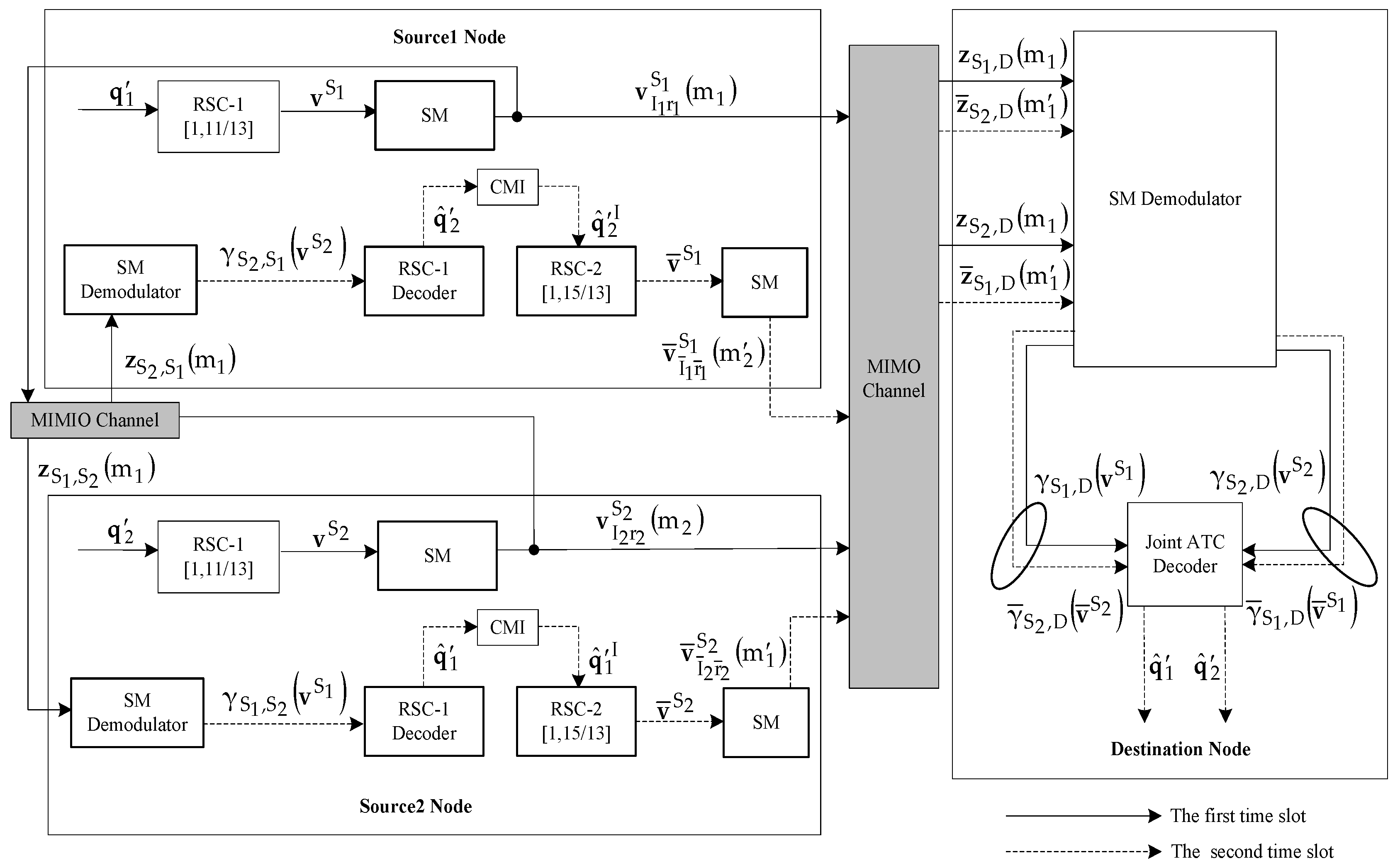
This subsection describes the two-source ATCC-SM scheme with the CMI. The block diagram of the two-source ATCC-SM scheme is illustrated in Figure 6, where two sources employ a full duplex mode and can simultaneously transmit and receive data.
The two-source ATCC-SM scheme needs to take two time slots to accomplish a complete transmission process. The solid and dashed lines with arrows represent the first and second time slots, respectively, as illustrated in Figure 6. During the first time slot, the input sequences q 1 and q 2 of length K at the source 1 ( S 1 ) node and the source 2 ( S 2 ) node are separately fed into the RSC-1 of the ATC encoder that generates the codeword v S 1 and v S 2 of length 2 K . After that, the obtained v S 1 and v S 2 are given to SM to output the following vectors:
v I 1 r 1 S 1 ( m 1 )   =   [ 0 ,   ,   0 ,   v r 1 S 1 ( m 1 ) ,   0 ,   ,   0 ] T ,           v I 2 r 2 S 2 ( m 2 )   =   [ 0 , ,   0 ,   v r 2 S 2 ( m 2 ) ,   0 , ,   0 ] T
The operation of SM is discussed in Section 2.2 of this manuscript. The output vector v I 1 r 1 S 1 ( m 1 ) is broadcasted to the S 2 and the destination node over the slow Rayleigh fading MIMO channel. Similarly, the vector v I 2 r 2 S 2 ( m 2 ) is propagated to S 1 and the destination node over the slow Rayleigh fading MIMO channel.
During the first time slot, S 2 and S 1 get the received vectors z S 1 , S 2 ( m 1 ) and z S 2 , S 1 ( m 1 ) , which can be mathematically modeled as:
z S 1 , S 2 ( m 1 )   =   H S 1 , S 2 v I 1 r 1 S 1 ( m 1 )   +   n S 1 , S 2 ( m 1 )   =   h S 1 , S 2 I 1 ( m 1 )   v r 1 S 1 ( m 1 )   +   n S 1 , S 2 ( m 1 ) ,
z S 2 , S 1 ( m 1 )   =   H S 2 , S 1 v I 2 r 2 S 2 ( m 1 )   +   n S 2 , S 1 ( m 1 )   =   h S 2 , S 1 I 2 ( m 1 ) v r 2 S 2 ( m 1 )   +   n S 2 , S 1 ( m 1 )
where H S 1 , S 2 and H S 2 , S 1 represent the channel matrices of S 1 S 2 , and S 2 S 1 , respectively. H S 1 , S 2 and H S 2 , S 1 are defined similarly to H in Equation (13). h S 1 , S 2 I 1 ( m 1 ) and h S 2 , S 1 I 2 ( m 1 ) represent the I 1 ( m 1 ) th and I 2 ( m 1 ) th columns of H S 1 , S 2 and H S 2 , S 1 , respectively, and they are defined similarly to h I ( j ) in Equation (13). The vectors n S 1 , S 2 ( m 1 ) and n S 2 , S 1 ( m 1 ) denote the complex additive Gaussian noise from S 1 to S 2 , and from S 2 to S 1 , respectively. Both of them are defined like n ( j ) in Equation (13). Afterwards, the vectors z S 1 , S 2 ( m 1 ) and z S 2 , S 1 ( m 1 ) enter the SM demodulator of S 2 and S 1 , respectively. As a result, the LLRs γ S 1 , S 2 ( v S 1 ) and γ S 2 , S 1 ( v S 2 ) are obtained and are further given to the RSC-1 decoder to get the estimations q ^ 1 and q ^ 2 during the second time slot. It is worth mentioning that SM demodulator is made up of an SM demapper, a bit combiner and bit ungrouping blocks. Through the CMI, the generated estimations q ^ 1 and q ^ 2 are interleaved as q ^ 1 I and q ^ 2 I , respectively, which are re-encoded into codewords v = S 2 and v = S 1 by the RSC-2 encoder. Here, only the length K parity sequences v ¯ S 2 and v ¯ S 1 of v = S 2 and v = S 1 are employed by SM to produce vectors: v ¯ I ¯ 2 r ¯ 2 S 2 ( m 1 )   =   [ 0 ,   ,   0 ,   v ¯ r ¯ 2 S 2 ( m 1 ) ,   0 ,   ,   0 ] T and v ¯ I ¯ 1 r ¯ 1 S 1 ( m 2 )   =   [ 0 ,   ,   0 ,   v ¯ r ¯ 1 S 1 ( m 2 ) ,   0 ,   ,   0 ] T , respectively, sent to the corresponding destination node over the slow Rayleigh fading MIMO channel, where v ¯ r ¯ 2 S 2 ( m 1 ) and v ¯ r ¯ 1 S 1 ( m 1 ) with normalized transmission powers are in the I ¯ 2 ( m 2 ) th and I ¯ 2 ( m 2 ) th positions, with r ¯ 2 , r ¯ 2 { 1 ,   2 , , M } , I ¯ 2 ( m 1 ) , I ¯ 1 ( m 2 ) { 1 ,   2 , , N T } , m 1 { 1 ,   2 ,   3 , ,   K / d 1 } and m 2 { 1 ,   2 ,   3 , ,   K / d 2 } for d 1   =   d 2 and m 1   =   m 2 .
During the first time slot, the destination accepts the vectors z S 1 , D ( m 1 ) and z S 2 , D ( m 1 ) . Moreover, the destination also gets z ¯ S 1 , D ( m 1 ) and z ¯ S 2 , D ( m 1 ) during the second time slot. The received vectors at the destination can be mathematically modeled as
z S 1 , D ( m 1 )   =   H S 1 , D v I 1 r 1 S 1 ( m 1 )   +   n S 1 , D ( m 1 )   =   h S 1 , D I 1 ( m 1 ) v r 1 S 1 ( m 1 )   +   n S 1 , D ( m 1 )
z S 2 , D ( m 1 )   =   H S 2 , D v I 2 r 2 S 2 ( m 1 )   +   n S 2 , D ( m 1 )   =   h S 2 , D I 2 ( m 1 ) v r 2 S 2 ( m 1 )   +   n S 2 , D ( m 1 )
z ¯ S 1 , D ( m 1 )   =   H ¯ S 1 , D v ¯ I ¯ 1 r ¯ 1 S 1 ( m 1 )   +   n ¯ S 1 , D ( m 1 )   =   h ¯ S 1 , D I ¯ 1 ( m 1 ) v ¯ r ¯ 1 S 1 ( m 1 )   +   n ¯ S 1 , D ( m 1 )
z ¯ S 2 , D ( m 1 )   =   H ¯ S 2 , D v ¯ I ¯ 2 r ¯ 2 S 2 ( m 1 )   +   n ¯ S 2 , D ( m 1 )   =   h ¯ S 2 , D I ¯ 2 ( m 1 ) v ¯ r ¯ 2 S 2 ( m 1 )   +   n ¯ S 2 , D ( m 1 )
where H S 1 , D represents the channel matrix of S 1 to the destination node, and H S 2 , D denotes the channel matrix of S 2 to the destination in the first time slot. However, H ¯ S 1 , D represents the channel matrix of S 1 to the destination node, and H ¯ S 2 , D denotes the channel matrix of S 2 to a destination in the second time slot. All the channel matrices are defined similarly to H in (13). In Equations (19) and (20), h S 1 , D I 1 ( m 1 ) and h S 2 , D I 2 ( m 1 ) denote the I 1 ( m 1 ) th and I 2 ( m 1 ) th columns of H S 1 , D and H S 2 , D , respectively. Similarly, h ¯ S 1 , D I ¯ 1 ( m 1 ) and h ¯ S 2 , D I ¯ 2 ( m 1 ) from Equations (21) and (22) represent the I ¯ 1 ( m 1 ) th and I ¯ 2 ( m 1 ) th columns of H ¯ S 1 , D and H ¯ S 2 , D , respectively. The definitions of h S 1 , D I 1 ( m 1 ) , h S 2 , D I 2 ( m 1 ) , h ¯ S 1 , D I ¯ 1 ( m 1 ) and h ¯ S 2 , D I ¯ 2 ( m 1 ) are similar to that of h I ( j ) in Equation (13). In addition, n S 1 , D ( m 1 ) , n S 2 , D ( m 1 ) , n ¯ S 1 , D ( m 1 ) and n ¯ S 1 , D ( m 1 ) denote complex addictive Gaussian noise, and they are defined similarly to n ( j ) in Equation (13).
At the destination node, the SM demodulator performs soft demodulation for z S 1 , D ( m 1 ) , z ¯ S 2 , D ( m 1 ) , z S 2 , D ( m 1 ) and z ¯ S 1 , D ( m 1 ) to obtain the LLRs γ S 1 , D ( v S 1 ) , γ ¯ S 2 , D ( v ¯ S 2 ) , γ S 2 , D ( v S 2 ) and γ ¯ S 1 , D ( v ¯ S 1 ) , respectively. Eventually, the LLRs γ S 1 , D ( v S 1 ) and γ ¯ S 2 , D ( v ¯ S 2 ) are fed to the joint ATC decoder that produces the estimate of q ^ 1 . Similarly, γ S 2 , D ( v S 2 ) and γ ¯ S 1 , D ( v ¯ S 1 ) feed into the joint ATC decoder to generate q ^ 2 . The specific decoding process for the joint ATC decoder is presented in Section 4 of this paper.

3.2. Two-Source Asymmetric Turbo-Coded Cooperative VBLAST (ATCC-VBLAST) Scheme Based on CMI

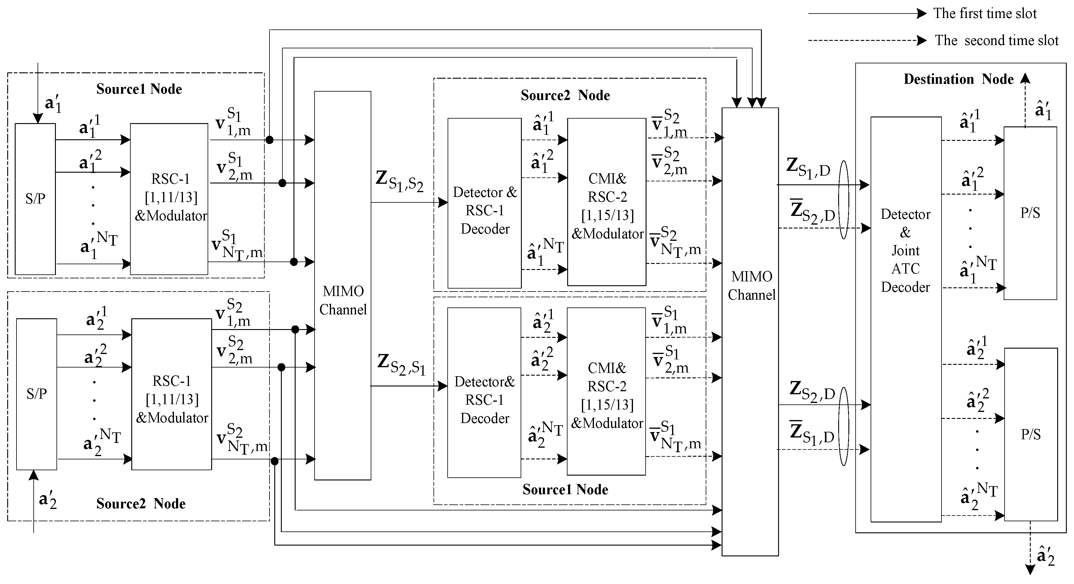
The two-source ATCC-VBLAST scheme based on the CMI is described in this section. Figure 7 shows the schematic diagram of the two-source ATCC-VBLAST scheme with the CMI in which two sources employ full duplex mode and simultaneously transmit and receive data. This scheme also requires two time slots to complete transmission. The solid and dashed lines with arrows indicate the first and the second time slots, respectively.
At the S 1 node, the input sequence a 1 of length K is firstly converted by S/P conversion into length K / N T parallel sequences a 1 1 , a 1 2 , …, and a 1 N T in the first time slot. The resulting sequence is passed to RSC-1 encoder and the M-PSK/QAM modulator that produces the modulated sequences v 1 , m S 1 , v 2 , m S 1 ,   , and v N T , m S 1 with dimension 1 × L1. The following transmission matrix
V m S 1   =   [ ( v 1 , m S 1 ) T ,   ( v 2 , m S 1 ) T ,   ,   ( v N T , m S 1 ) T ] T ,
which consists of the modulated sequences, is broadcasted to S 2 and the destination node through the slow Rayleigh fading MIMO channel. Likewise, the transmission matrix at S 2 is:
V m S 2   = [ ( v 1 , m S 2 ) T ,   ( v 2 , m S 2 ) T ,   ,   ( v N T , m S 2 ) T ] T ,
which is similar to V m S 1 given in Equation (23). Next, the matrix V m S 2 is transmitted towards S 1 and the destination node over the slow Rayleigh fading MIMO channel. During the first time slot, the received matrices Z S 1 , S 2 , Z S 2 , S 1 , Z S 1 , D and Z S 2 , D are mathematically modelled as:
Z S 1 , S 2 =   H S 1 , S 2 V m S 1   +   N S 1 , S 2 ,                 Z S 2 , S 1 =   H S 2 , S 1 V m S 2   +   N S 2 , S 1
Z S 1 , D   =   H S 1 , D V m S 1   +   N S 1 , D ,                     Z S 2 , D   =   H S 2 , D V m S 2   +   N S 2 , D ,
where H S 1 , S 2 , H S 2 , S 1 , H S 1 , D , and H S 2 , D represent the channel matrices of S 1 S 2 , S 2 S 1 , S 1 to destination, and S 2 to destination, respectively, and are defined similarly to H in Equation (13). N S 1 , S 2 , N S 2 , S 1 , N S 1 , D , and N S 2 , D denote the complex additive Gaussian noise of S 1 S 2 , S 2 S 1 , S 1 to destination, and S 2 to destination, respectively, and are defined similarly to N in Equation (15).
The matrices Z S 1 , S 2 and Z S 2 , S 1 are fed into the VBLAST detector and the RSC-1 decoder to produce the estimated sequences a ^ 1 1 , a ^ 1 2 , …, a ^ 1 N T , and a ^ 2 1 , a ^ 2 2 , …, a ^ 2 N T , respectively. These sequences are delivered to the CMI, the RSC-2 encoder and the M-PSK/QAM modulator to get 1 × (L1/2) dimensional modulated parity sequences V ¯ 1 , m S 2 , V ¯ 2 , m S 2 , V ¯ N T , m S 2 and V ¯ 1 , m S 1 , V ¯ 2 , m S 1 , V ¯ N T , m S 1 , respectively. After that, the newly re-arranged matrices
V ¯ m S 2   =   [ ( v ¯ 1 , m S 2 ) T ,   ( v ¯ 2 , m S 2 , ) T ,   ,   ( v ¯ N T , m S 2 ) T ] T , V ¯ m S 1   =   [ ( v ¯ 1 , m S 1 ) T ,   ( v ¯ 2 , m S 1 , ) T ,   ,   ( v ¯ N T , m S 2 ) T ] T
from S 2 and S 1 are transmitted towards the common destination node. During the second time slot, the received matrices Z ¯ S 2 , D and Z ¯ S 1 , D at the receiving end are written as:
Z ¯ S 2 , D = H ¯ S 2 , D V ¯ m S 2 + N ¯ S 2 , D , Z ¯ S 1 , D = H ¯ S 1 , D V ¯ m S 1 + N ¯ S 1 , D
where H ¯ S 2 , D and H ¯ S 1 , D represent the channel matrices of S 2 to destination and S 1 to destination, respectively. H ¯ S 2 , D and H ¯ S 1 , D are defined similarly to H in Equation (13). N ¯ S 2 , D and N ¯ S 1 , D denote the complex additive Gaussian noise of S 2 to destination and S 1 to destination, respectively. They are defined like N in Equation (15).
The destination node gets the matrices Z S 1 , D and Z S 2 , D in the first time slot. During the second time slot, the destination accepts Z ¯ S 2 , D and Z ¯ S 1 , D . Z S 1 , D and Z ¯ S 2 , D are given to the VBLAST detector and the joint ATC decoder to produce the estimated sequences a ^ 1 1 , a ^ 1 2 , …, and a ^ 1 N T . These sequences are combined into sequence a ^ 1 through the P/S converter. Similarly, the remaining Z S 2 , D and Z ¯ S 1 , D are fed to the VBLAST detector and the joint ATC decoder to generate the estimations a ^ 2 1 , a ^ 2 2 , …, and a ^ 2 N T , which are merged into a ^ 2 by the P/S converter. The description of the joint ATC decoder is given in the next section.

4. Joint Iterative ATC Decoder

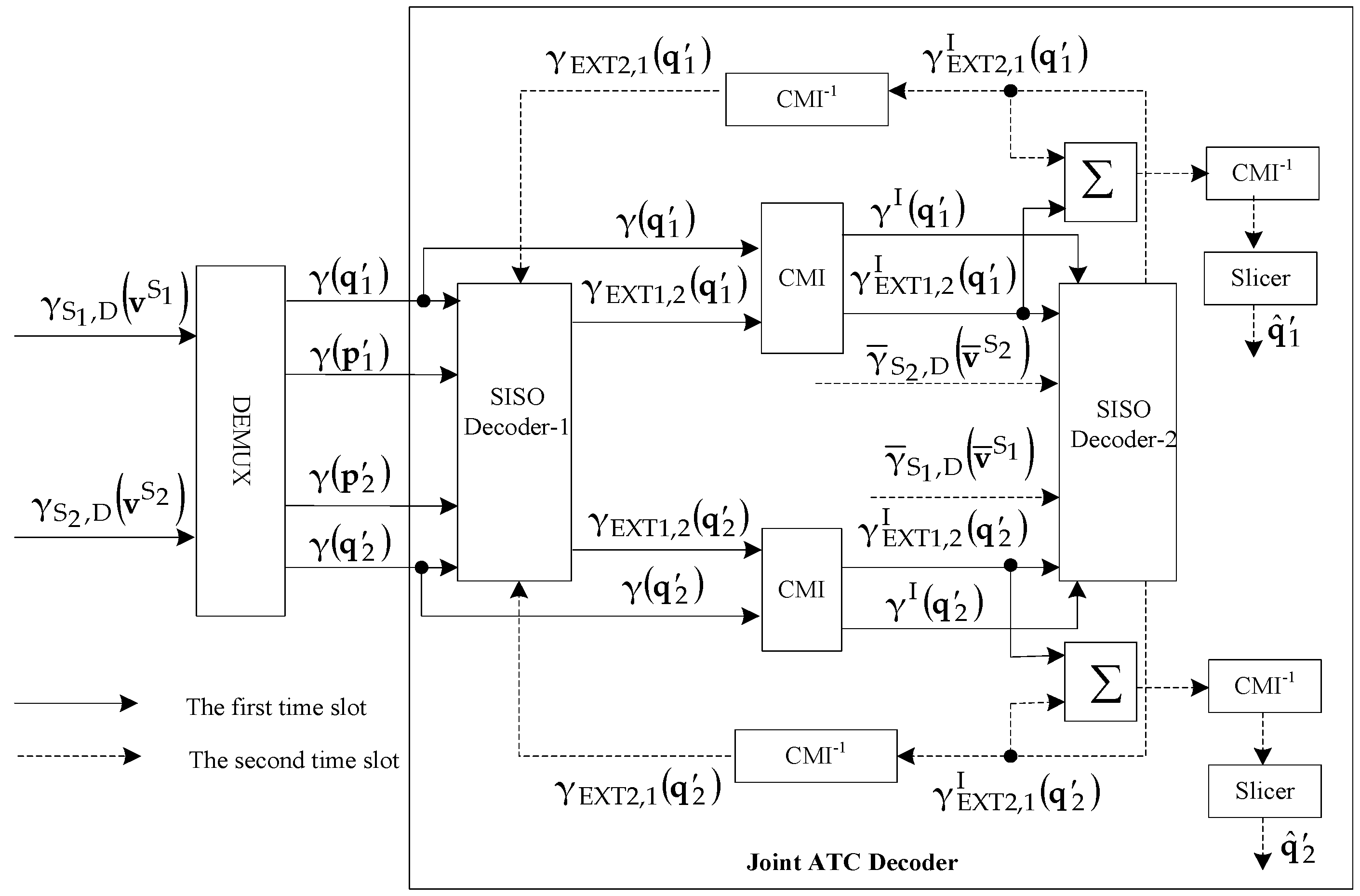
Another elegant feature for the ATC-coded cooperative architecture is the joint iterative ATC decoding employed at the destination. The joint ATC decoder consists of two different soft input soft output (SISO) decoders, as given in the literature [33]. For simplicity, the diagram of the joint iterative log maximum a posterior (log-MAP) [34,35] ATC decoder of two-source ATCC-SM in Section 3.1 is shown in Figure 8.
In Figure 8, the LLRs γ S 1 , D ( v S 1 ) and γ S 2 , D ( v S 2 ) are de-multiplexed into pairs of γ ( q 1 ) and γ ( p 1 ) , and pairs of γ ( q 2 ) and γ ( p 2 ) by the de-multiplexer, where γ ( q 1 ) and γ ( q 2 ) denote the LLRs of systematic bits q 1 and q 2 , whereas γ ( p 1 ) and γ ( p 2 ) represent the LLRs of the parity bits p 1 and p 2 , respectively.
During the first time slot, the LLRs γ ( q 1 ) and γ ( p 1 ) are fed into SISO decoder-1 to generate extrinsic information γ EXT 1 , 2 ( q 1 ) . Similarly, γ ( q 2 ) , together with γ ( p 2 ) , is given as an input to SISO decoder-1 that produces extrinsic information γ EXT 1 , 2 ( q 2 ) . These LLRs γ ( q 1 ) , γ ( q 2 ) , γ EXT 1 , 2 ( q 1 ) and γ EXT 1 , 2 ( q 2 ) are interleaved into γ I ( q 1 ) , γ I ( q 2 ) , γ EXT 1 , 2 I ( q 1 ) and γ EXT 1 , 2 I ( q 2 ) , respectively, by passing through the CMI. Next, γ I ( q 1 ) and γ EXT 1 , 2 I ( q 1 ) , together with parity LLRs γ ¯ S 2 , D ( v ¯ S 2 ) , are delivered to SISO decoder-2. During the second time slot, the extrinsic information γ EXT 2 , 1 I ( q 1 ) is generated. Similarly, SISO decoder-2 accepts γ I ( q 2 ) , γ EXT 1 , 2 I ( q 2 ) and γ ¯ S 1 , D ( v ¯ S 1 ) to produce extrinsic information γ EXT 2 , 1 I ( q 2 ) . Afterwards, γ EXT 2 , 1 I ( q 1 ) and γ EXT 2 , 1 I ( q 2 ) are passed through the CMI−1 to generate the de-interleaved sequences γ EXT 2 , 1 ( q 1 ) and γ EXT 2 , 1 ( q 2 ) , which are given back to SISO decoder-1 for the next iteration, as shown in Figure 8. After reaching a specific number of iterations, the extrinsic information γ EXT 1 , 2 I ( q 1 ) and γ EXT 2 , 1 I ( q 1 ) are summed up and delivered to the de-interleaver and slicer that finally estimates sequence q ^ 1 . Similarly, the estimation q ^ 2 is generated when the sum of γ EXT 1 , 2 I ( q 2 ) and γ EXT 2 , 1 I ( q 2 ) is considered as the input of the de-interleaver and the slicer.

5. Results and Discussion

The simulation results of ATC-SM, ATC-VBLAST, ATCC-SM and ATCC-VBLAST are discussed in this section. The slow Rayleigh fading channel was assumed for all the schemes. Two source nodes and a destination node were equipped with multiple antennas, and the two sources had an identical number of antennas. Monte Carlo simulations were executed in a MATLAB environment. Different numbers of receive antennas, modulation schemes, and various information lengths were chosen in different scenarios. During the simulation, all the schemes were required to achieve a very low BER. such as 10−6. Therefore, the running of all the simulations of the proposed schemes under different conditions needed to take some time. Furthermore, the execution times may have varied when using different computers to run the simulations. For a fair comparison, the log-MAP decoding algorithm was employed in all simulations. All the schemes adopted RSC encoders with the same generator polynomial ( 11 / 13 ; 15 / 13 ) . The number of decoding iterations was four. The overall code rate at the destination node was the same, i.e., R = 1/3 between the non-cooperative and cooperative schemes. In the coded cooperative scheme, we supposed that S 2 was placed near to the destination than S 1 such that a 1 dB gain in SNR was given to S 2 , i.e., χ S 2 D   =   χ S 1 D   +   1 . Moreover, a non-ideal inter-user channel was assumed for all coded-cooperative simulations.
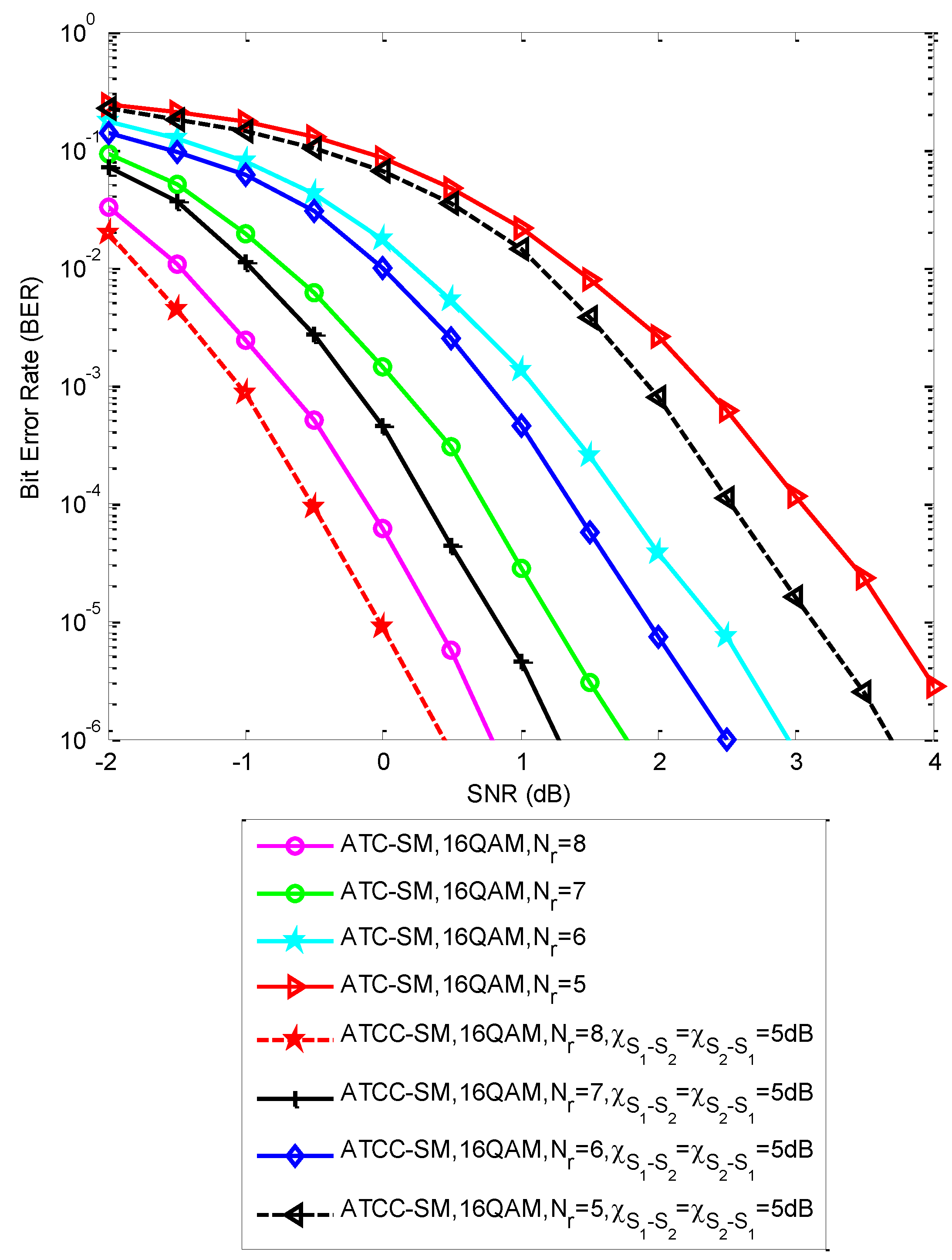
Figure 9 demonstrates the BER performance of the two-source ATCC-SM scheme under the non-ideal inter-user channel scenario and the ATC-SM scheme based on the CMI over the slow Rayleigh fading channel. 16QAM was chosen as the modulation scheme. The number of antennas at the sources was N t   =   8 , and the number of receive antennas at the destination was taken as N r = 5, 6, 7 and 8. Furthermore, the information length was taken as K = 1024 in the simulation. Through the simulated results, it can be evidently observed that the cooperative scheme outperformed its counterpart non-cooperative scheme under identical conditions. We assumed that the inter-user channel had a 5 dB gain, i.e., χ S 1 S 2   =   χ S 2 S 1   =   5   dB . For the case of N r = 6 , the proposed two-source ATCC-SM achieved a performance gain of about 0.5 dB at BER of 10−6 over ATC-SM. The prominent performance improvement was made possible due to the deployment of the joint ATC decoder at the destination. In addition, the system performance improved as the number of the receive antennas increased. For the case of the eight receive antennas, both the ATC-SM and two-source ATCC-SM configurations were superior to that of the seven receive antennas in the whole SNR range, as depicted in Figure 9. The phenomenon can be explained by the fact that deploying more receive antennas yielded the additional spatial diversity gain in the MIMO system.
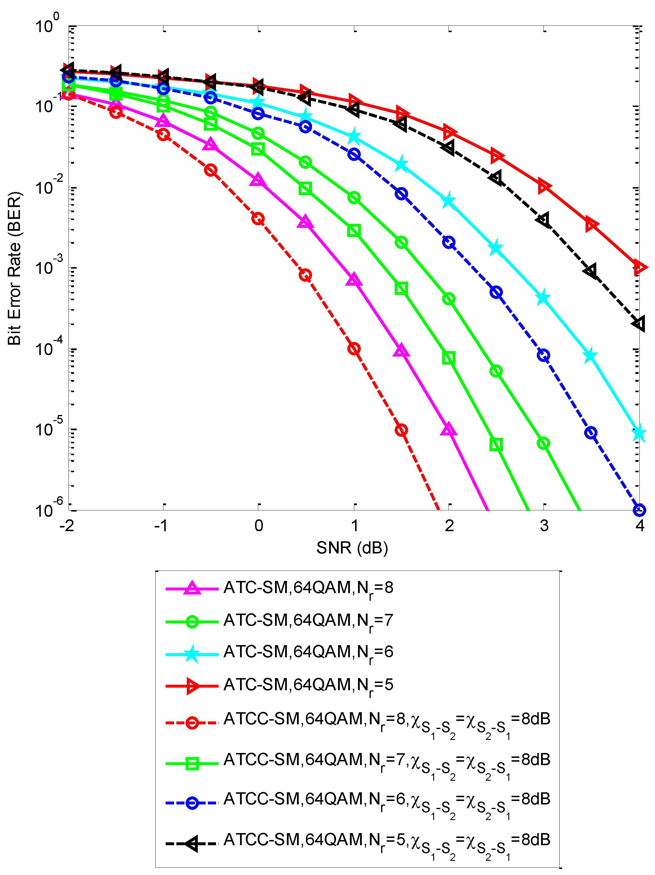
To confirm the effectiveness of the cooperative system, we further investigated the BER performance of the proposed two-source ATCC-SM scheme under a non-ideal inter-user channel scenario and ATC-SM based on the CMI in 32QAM and 64QAM over the slow Rayleigh fading channel, as shown in Figure 10 and Figure 11, respectively. The parameters K = 1024, N t = 8 and different numbers of receive antennas, i.e., N r = 5, 6, 7 and 8, were employed in the simulations. It was assumed that the link between two sources had an SNR of χ S 1 S 2   =   χ S 2 S 1   =   6   dB and χ S 1 S 2   =   χ S 2 S 1   =   8   dB for 32QAM and 64QAM, respectively. The simulated results demonstrate the superiority of the cooperative system as compared to the non-cooperative system. Furthermore, the BER performance obtained an obvious improvement with the increase of the number of receive antennas under identical conditions, as expected.
Figure 12 exhibits the BER performance comparison for ATC-SM based on the CMI with different modulation schemes over the slow Rayleigh fading channel. The antenna configuration of N r   =   N t   =   8 was adopted. Moreover, the information length was taken as K = 1024. The simulated results illustrate that the scheme in 16QAM outperformed its counterpart in 32QAM in terms of BER performance under identical conditions. Similarly, the configuration with 32QAM was better than that of 64QAM. This was due to the fact that high-order modulation was more sensitive against bit errors, thus causing system degradation, as compared with a lower order modulation.
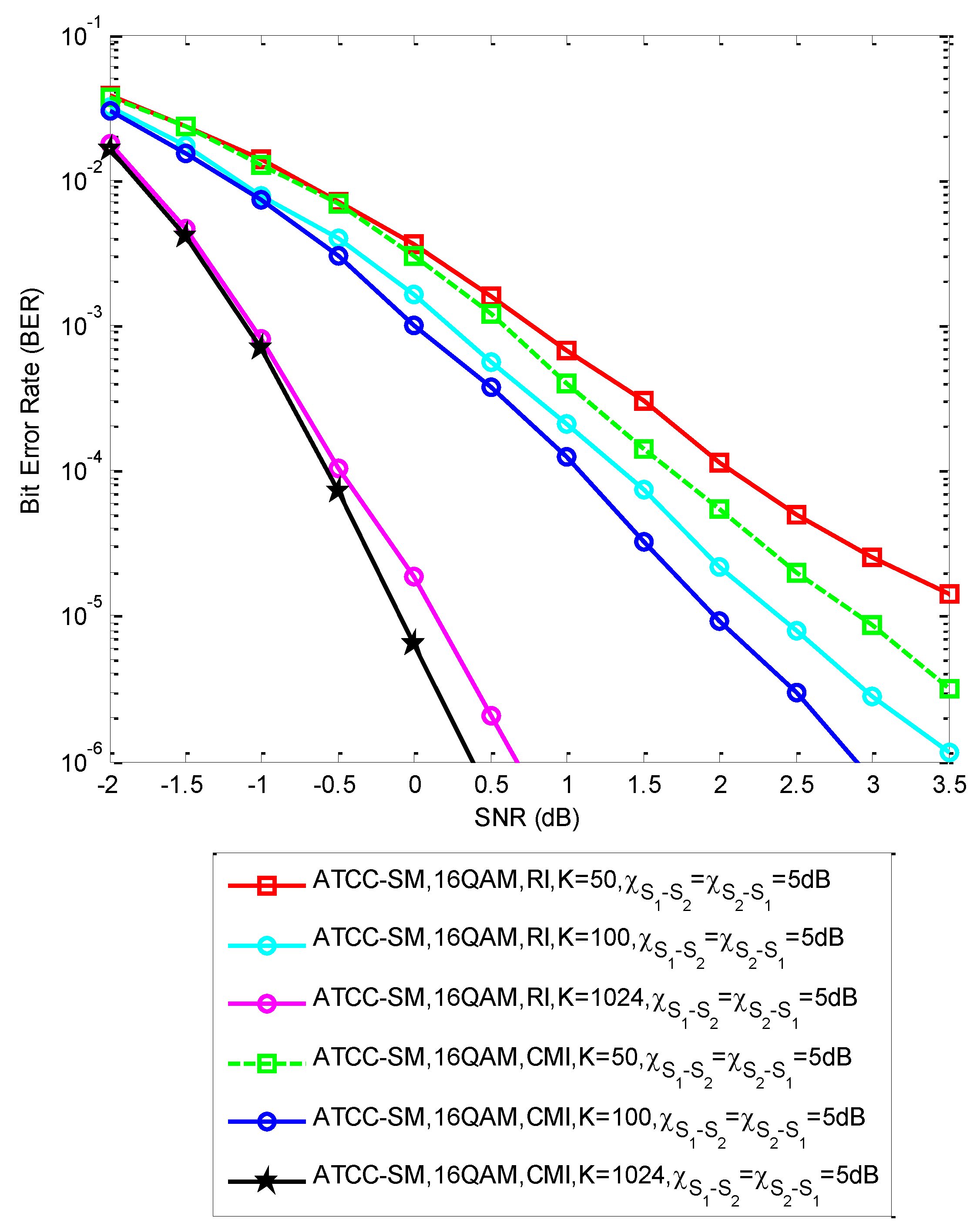
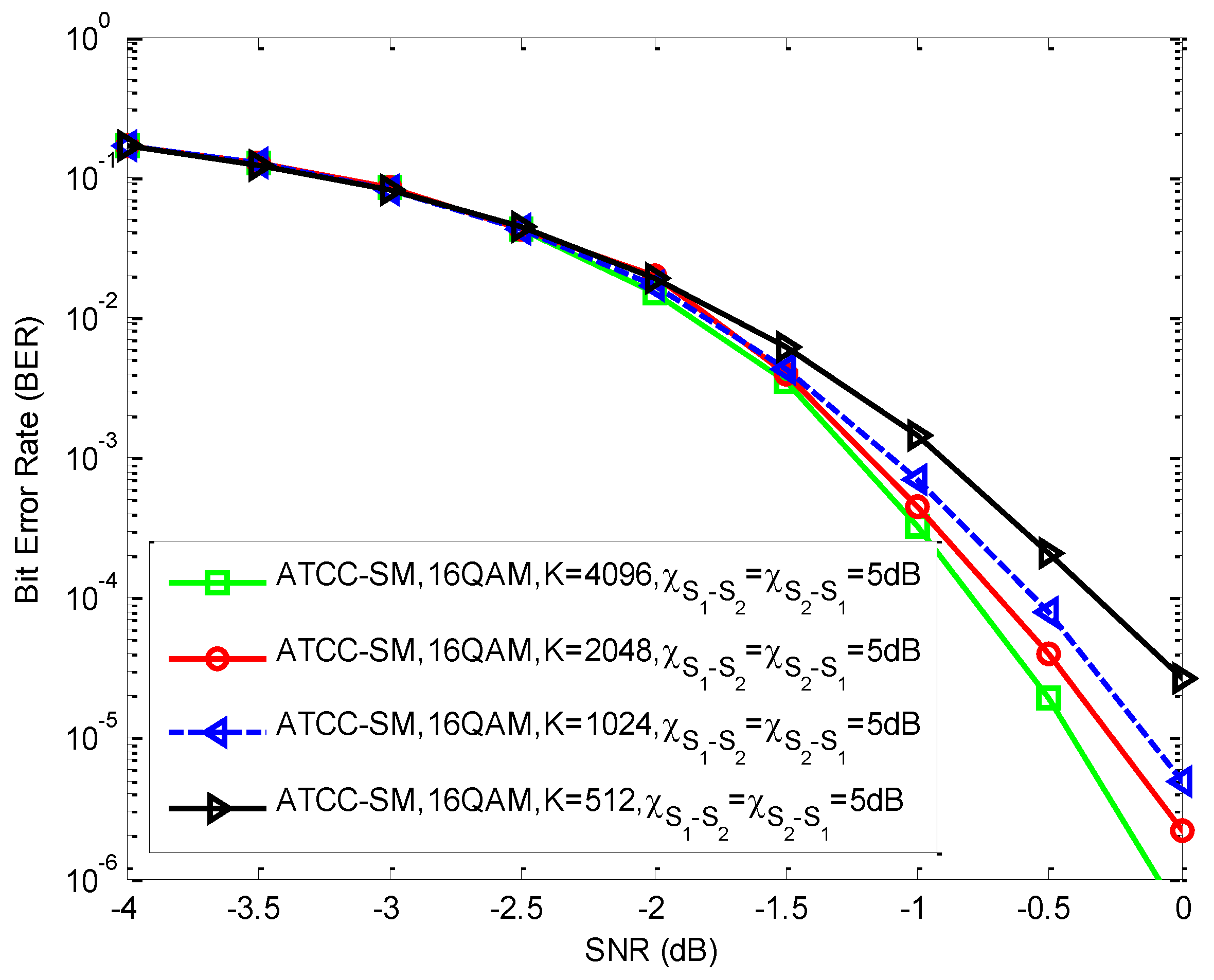
Figure 13 shows the BER performance of the two-source ATCC-SM over 16QAM based on the CMI and the random interleaver (RI) with K = 50, 100 and 1024 under a non-ideal inter-user channel scenario, i.e., χ S 1 S 2   =   χ S 2 S 1   =   5   dB over the slow Rayleigh fading channel. The antenna configuration N r   =   N t   =   8 was employed. The Monte Carlo simulated results clearly demonstrate that the system with the CMI offered a superior performance as compared to its counterpart with an RI at a whole SNR range over the same block length. This was based on the fact that the CMI effectively broke the short weight sequences by increasing the minimum free distance of the turbo codes. Furthermore, we can observe from Figure 13 that the gains of 0.5, 0.4, and 0.25 dB were obtained at BER 10 5 for K = 50, 100 and 1024 relative to the RI, respectively. This implies that the CMI can be used to effectively improve short packet communication scenarios, such as K < 200. In Figure 14, the BER performance of the two-source ATCC-SM over 16QAM based on the CMI for K   =   512 ,   1024 ,   2048   and   4096 under χ S 1 S 2   =   χ S 2 S 1   =   5   dB through the slow Rayleigh fading channel are shown. The antenna configuration was taken as N r   =   N t   =   8 . The simulated results reveal that the system performance improved as the information length increased under identical conditions.
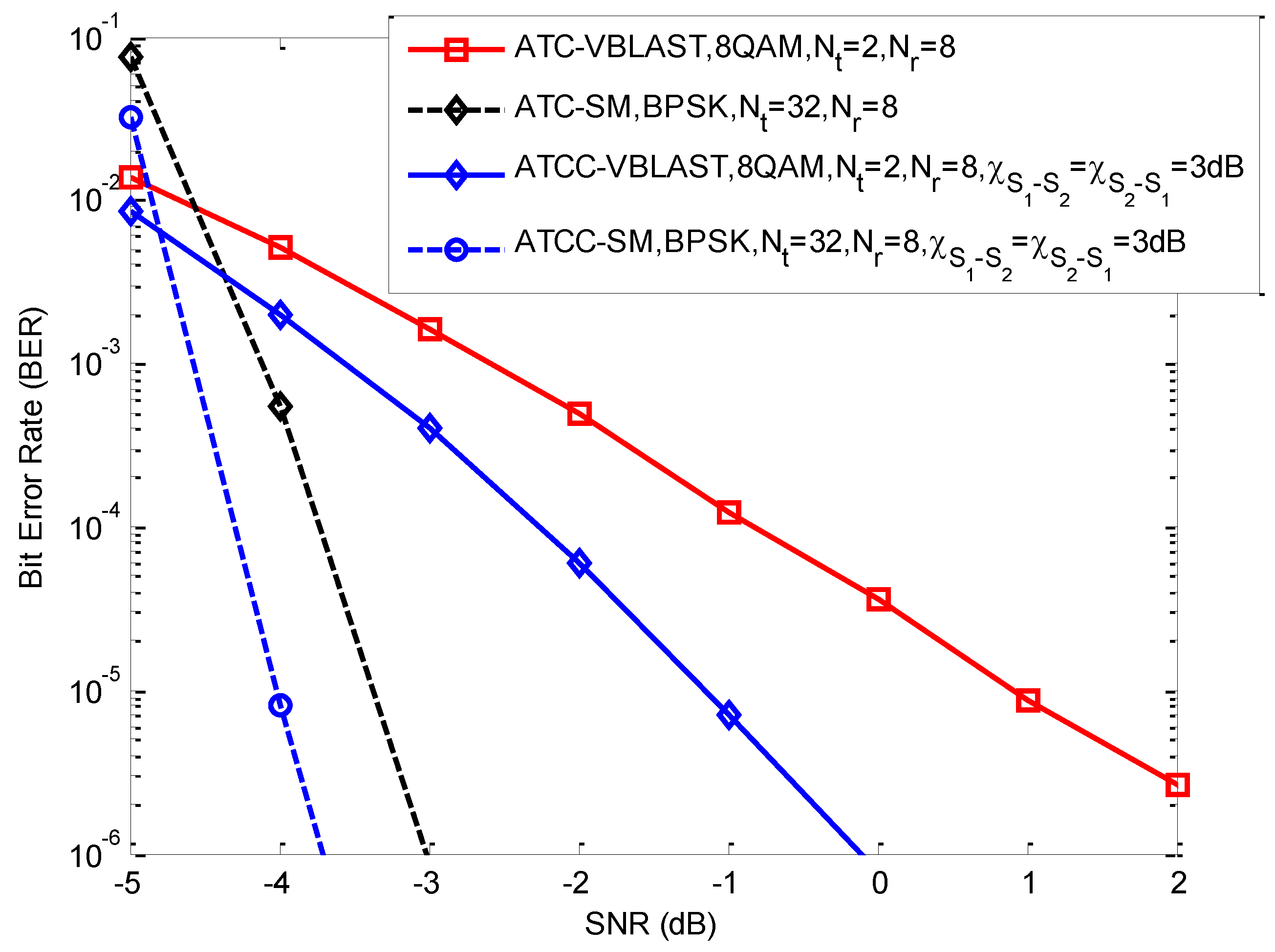
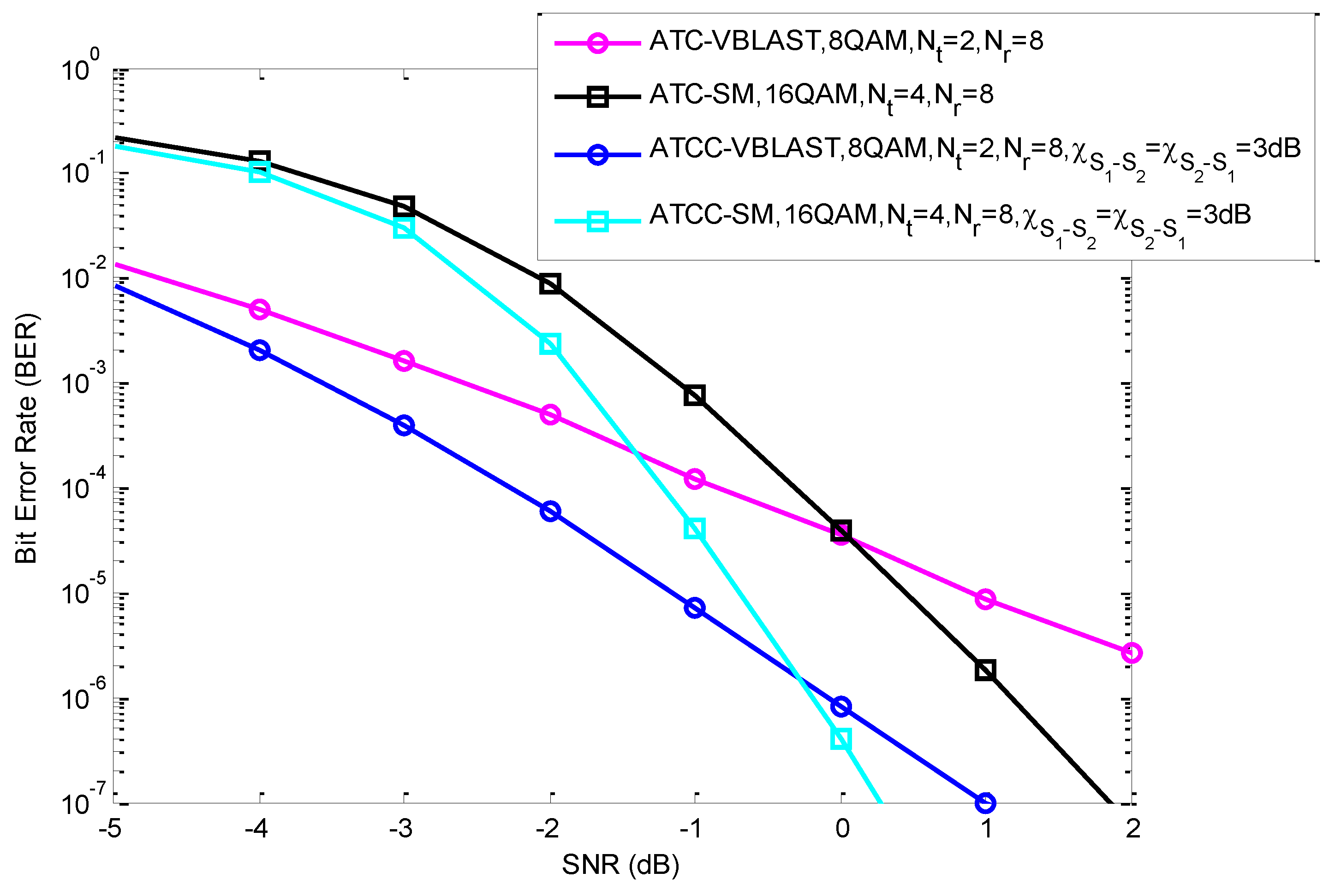
Figure 15 demonstrated the BER performance comparison of ATC-SM over BPSK, two-source ATCC-SM over BPSK under χ S 1 S 2   =   χ S 2 S 1   =   3   dB , ATC-VBLAST over 8QAM, and two-source ATCC-VBLAST over 8QAM under χ S 1 S 2   =   χ S 2 S 1   =   3   dB through the slow Rayleigh fading channel for 6b/s/Hz transmission. Furthermore, a BER performance comparison among ATC-SM in 16QAM, two-source ATCC-SM in 16QAM under χ S 1 S 2   =   χ S 2 S 1   =   3   dB , ATC-VBLAST in 8QAM, and two-source ATCC-VBLAST in 8QAM under χ S 1 S 2 =   χ S 2 S 1 = 3   dB over the slow Rayleigh fading channel for the same case of 6b/s/Hz transmission is presented in Figure 16. Both ATC-SM and ATCC-SM over BPSK had N t   =   32 and N r   =   8 antenna configurations. However, both ATC-SM and ATCC-SM over 16QAM had different antenna configurations, i.e., N t   =   4 and N r   =   8 . In ATC-VBLAST and ATCC-VBLAST over 8QAM, N t   =   2 and N r   =   8 were adopted. In addition, the information length K = 2048 and the CMI were utilized in the simulation. As seen from Figure 15 and Figure 16, two-source ATCC-SM and two-source ATCC-VBLAST outperformed ATC-SM and ATC-VBLAST, respectively. Moreover, we can discover from Figure 15 that ATC-SM was better than ATC-VBLAST at an SNR of greater than −4.5 dB, while two-source ATCC-SM outperformed two-source ATCC-VBLAST at an SNR of greater than −4.7 dB. Figure 16 reveals that at an SNR of greater than 0 dB, the BER performance of ATC-SM exceeded ATC-VBLAST, whereas at an SNR of greater than −0.2 dB, the BER performance of two-source ATCC-SM was superior to the two-source ATCC-VBLAST. This was because both the ATC-SM and two-source ATCC-SM schemes took advantage of a low modulation order, i.e., BPSK, as compared to a high order modulation, such as 16QAM.

6. Conclusions

In this paper, a two-source ATCC-SM over the slow Rayleigh fading MIMO channel is proposed. We analyzed the BER performance of the ATCC-SM scheme through different conditions such as various numbers of receive antennas, modulation techniques, and information lengths. In order to perform a fair comparison, an analysis for the BER performance of ATC-SM in the non-cooperative scenario was also implemented. Through the Monte Carlo simulated results, it can be seen that the cooperative scheme has a significant performance gain as compared to its non-cooperative counterpart under identical conditions. This is due to the fact that the joint ATC decoder results in a BER performance gain. Finally, we carried out a BER performance comparison between the two-source ATCC-SM and two-source ATCC-VBLAST under identical conditions, and the Monte Carlo simulations evidently demonstrate the effectiveness and usefulness of the two-source ATCC-SM scheme.

Author Contributions

C.Z. conceived the idea. She developed the mathematical models and performed the Monte Carlo simulations. F.Y. checked the mathematical model and the simulated results. R.U. and S.M. revised the manuscript. All authors have read and approved the final version of manuscript before its first submission to a journal.

Funding

This research was funded by the National Natural Science Foundation of China, under Grant number 61771241.

Acknowledgments

The authors would like to thank the Editor and anonymous reviewers for their precious suggestions, comments and reviews that help in improving the quality of this manuscript.

Conflicts of Interest

There is no conflict of interest related to the content of this manuscript.

References

  1. Barry, J.R.; Lee, E.A.; Messerschmitt, D.G. Digital Communication, 3rd ed.; Springer: New York, NY, USA, 2004; ISBN 978-1-4615-0227-2. [Google Scholar]
  2. Mughal, S.; Yang, F.-F.; Xu, H. Polar Coded Space-time Block Coded Spatial Modulation Based on Plotkin’s Construction for Coded Cooperative Networks. IET Commun. 2018, 12, 237–245. [Google Scholar] [CrossRef]
  3. Umar, R.; Yang, F.-F.; Xu, H. Multi-level construction of polar coded single carrier-FDMA based on MIMO antennas for coded cooperative wireless communications. IET Commun. 2018, 12, 1253–1262. [Google Scholar] [CrossRef]
  4. Garg, J.; Mehta, R.; Gupta, K. A Review on cooperative communication protocols in wireless world. Int. J. Wirel. Mob. Netw. 2013, 5, 107–126. [Google Scholar] [CrossRef]
  5. Sendonaris, A.; Erkip, E.; Aazhang, B. User cooperation diversity. Part I. System description. IEEE Trans. Commun. 2003, 51, 1927–1938. [Google Scholar] [CrossRef] [Green Version]
  6. Sendonaris, A.; Erkip, E.; Aazhang, B. User cooperation diversity. Part II. System description. IEEE Trans. Commun. 2003, 51, 1939–1948. [Google Scholar] [CrossRef] [Green Version]
  7. Hunter, T.E.; Nosratinia, A. Diversity through coded cooperation. IEEE Trans. Wirel. Commun. 2006, 5, 283–289. [Google Scholar] [CrossRef] [Green Version]
  8. Martinez, J.E.; Crespo, P.M. Depolarizing Channel Mismatch and Estimation Protocols for Quantum Turbo codes. Entropy 2019, 21, 1133. [Google Scholar] [CrossRef] [Green Version]
  9. Nguyen, T.T.B.; Tan, T.N.; Lee, H. Efficient QC-LDPC Encoder for 5G New Radio. Electronics 2019, 8, 668. [Google Scholar] [CrossRef] [Green Version]
  10. Goela, N.; Abbe, E.; Gastpar, M. Polar codes for broadcast channels. IEEE Trans. Inf. Theory 2015, 61, 758–782. [Google Scholar] [CrossRef] [Green Version]
  11. Wu, X.P.; Haas, H.; Grant, P.M. Cooperative spatial modulation for cellular networks. IEEE Trans. Commun. 2018, 66, 3683–3693. [Google Scholar] [CrossRef]
  12. He, C.; Gitlin, R.D. System performance of cooperative massive MIMO downlink 5G cellular systems. In Proceedings of the IEEE 17th Annual Wireless and Microwave Technology Conference, Clearwater, FL, USA, 11–13 April 2016. [Google Scholar] [CrossRef]
  13. Shamganth, K.; Sibley, M.J.N. A survey on relay selection in cooperative device-to-device (D2D) communication for 5G cellular networks. In Proceedings of the IEEE International Conference on Energy, Communications, Data Analytics and Soft Computing, Chennai, India, 1–2 August 2017. [Google Scholar] [CrossRef]
  14. Mesleh, R.Y.; Haas, H. Spatial modulation. IEEE Trans. Veh. Technol. 2008, 57, 2228–2241. [Google Scholar] [CrossRef]
  15. Basar, E.; Aygolu, U. New trellis code design for spatial modulation. IEEE Trans. Wirel. Commun. 2011, 10, 2670–2680. [Google Scholar] [CrossRef]
  16. Kamruzzaman, M.M. Relay Assisted Multiple Input Multiple Output Wireless Communication System for Multiple Access Channel Coding Using Hybrid-STBC-VBLAST. In Proceedings of the 26th Wireless and Optical Communication Conference, Newark, NJ, USA, 7–8 April 2017. [Google Scholar] [CrossRef]
  17. Robles, J.; Cortez, J. Fast Scalable Fixed-Point Architecture Proposal of A QR Decomposition for STBC-VBLAST Receiver. In Proceedings of the Wireless Telecommunications Symposium, Chicago, IL, USA, 26–28 April 2017. [Google Scholar] [CrossRef]
  18. Jeganathan, J.; Ghrayeb, A.; Szczecinski, L. Spatial modulation: Optimal detection and performance analysis. IEEE Commun. Lett. 2008, 12, 545–547. [Google Scholar] [CrossRef]
  19. Govender, R.; Pillay, N.; Xu, H. Soft-output space-time block coded spatial modulation. IET Commun. 2014, 8, 2786–2796. [Google Scholar] [CrossRef]
  20. Feng, D.; Xu, H.; Zheng, J. Nonbinary LDPC-coded spatial modulation. IEEE Trans. Wirel. Commun. 2018, 17, 2786–2799. [Google Scholar] [CrossRef]
  21. Akuon, P.; Xu, H. Polar coded spatial modulation. IET Commun. 2014, 8, 1459–1466. [Google Scholar] [CrossRef]
  22. Mughal, S.; Yang, F.-F. Coded cooperative spatial modulation based on multi-level construction of polar code. Telecommun. Syst. 2019, 70, 435–446. [Google Scholar] [CrossRef]
  23. Berrou, C.; Glavieux, A. Near optimum limit error correcting coding and decoding: Turbo codes. IEEE Trans. Commun. 1996, 44, 1261–1271. [Google Scholar] [CrossRef] [Green Version]
  24. Umar, R.; Yang, F. Turbo Coded OFDM Combined with MIMO Antennas Based on Matched Interleaver for Coded-Cooperative Wireless Communication. Information 2017, 8, 63. [Google Scholar] [CrossRef] [Green Version]
  25. Bohorquez, R.G.; Nour, C.A. On the Equivalence of Interleavers for Turbo Codes. IEEE Wirel. Commun. Lett. 2015, 4, 58–61. [Google Scholar] [CrossRef] [Green Version]
  26. Kraidy, G.M. On Progressive Edge-Growth Interleavers for Turbo Codes. IEEE Commun. Lett. 2016, 20, 200–203. [Google Scholar] [CrossRef]
  27. Ejaz, S.; Yang, F.-F. Turbo codes with modified code matched interleaver for coded-cooperation in half-duplex wireless relay networks. Frequenz 2015, 69, 171–184. [Google Scholar] [CrossRef]
  28. Feng, W.; Yuan, J. A code-matched interleaver design for turbo codes. IEEE Trans. Commun. 2002, 50, 926–937. [Google Scholar] [CrossRef]
  29. Omeira, M.S.; Hamad, G.M. A Code-matched Collision-free S-random Interleaver for Turbo Codes. In Proceedings of the IEEE Seventh International Conference on Intelligent Computing and Information Systems, Cairo, Egypt, 12–14 December 2015. [Google Scholar] [CrossRef]
  30. Mughal, S.; Yang, F.-F.; Ejaz, S. Asymmetric turbo code for coded cooperative wireless communication based on matched interleaver with channel estimation and multi-receive antennas at the destination. Radioengineering 2017, 26, 878–889. [Google Scholar] [CrossRef]
  31. Ramasamy, K.; Siddiqi, M.U. A new class of asymmetric turbo code for 3g systems. AEU Int. J. Electron. Commun. 2006, 60, 447–458. [Google Scholar] [CrossRef]
  32. Choi, S.J.; Shim, S.J.; You, Y.H. Novel MIMO Detection with Improved Complexity for Near-ML Detection in MIMO-OFDM Systems. IEEE Access 2019, 7, 60389–60398. [Google Scholar] [CrossRef]
  33. Vaz, A.C.; Nayak, C.G.; Nayak, D. Performance Comparison between Turbo and Polar codes. In Proceedings of the 3rd International Conference on Electronics, Communication and Aerospace Technology, Coimbatore, India, 12–14 June 2019. [Google Scholar] [CrossRef]
  34. Vucetic, B.; Yuan, J. Turbo Codes: Principles and Applications; Springer: New York, NY, USA, 2012; ISBN 978-1-4615-4469-2. [Google Scholar]
  35. Liu, Z.; Wu, B.; Ye, T.C. Improved Turbo Decoding with Multivariable Taylor Series Expansion. IEEE Commun. Lett. 2018, 22, 37–40. [Google Scholar] [CrossRef]
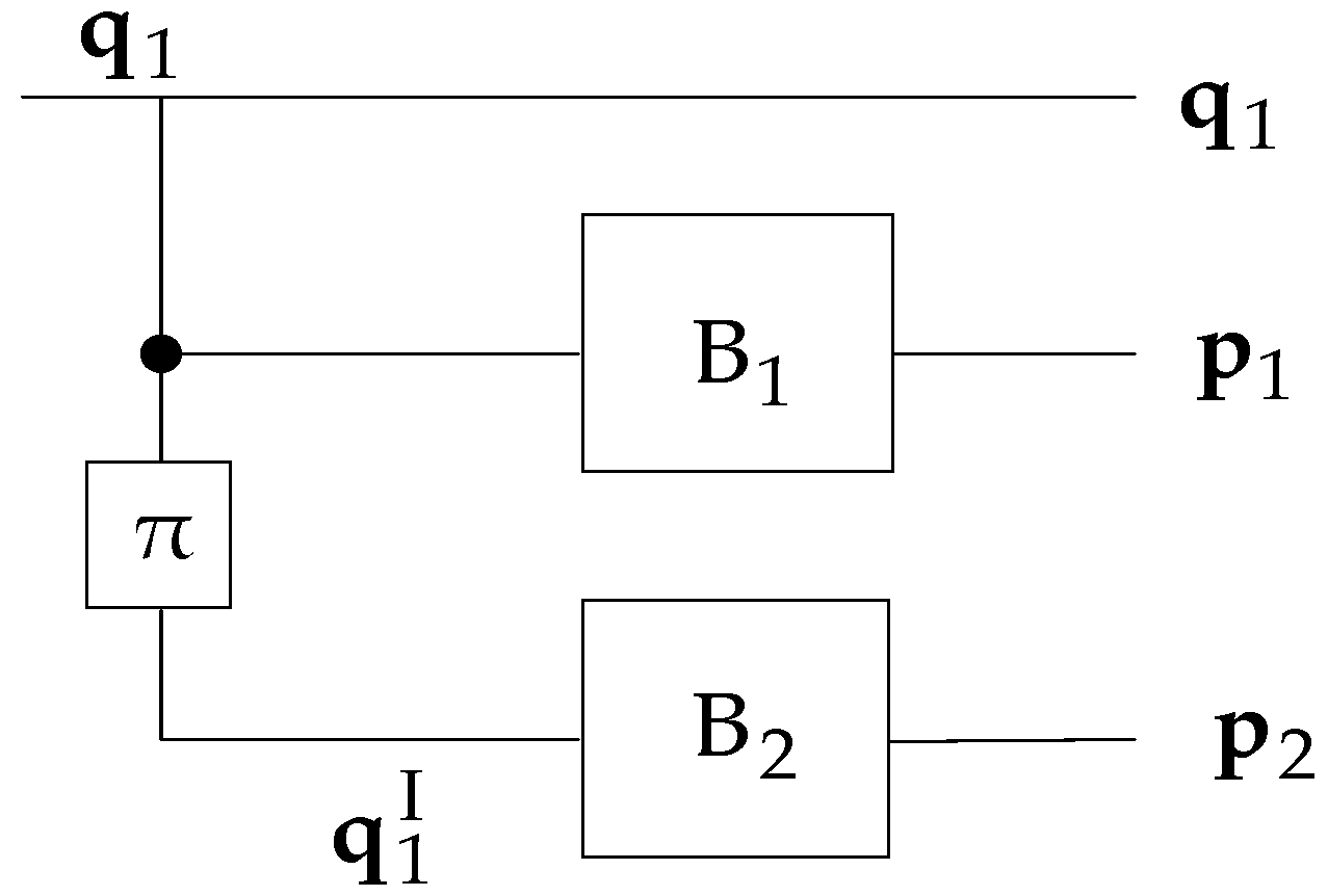
Figure 1. The concatenation of the asymmetric turbo code (ATC).
Electronics 09 00169 g001
Figure 2. A weight-2 input sequence is mapped to another weight-2 input sequence after passing through the interleaver.
Electronics 09 00169 g002
Figure 3. A weight-4 input sequence is mapped to another weight-4 input sequence after passing through the interleaver.
Electronics 09 00169 g003
Figure 4. Non-cooperative asymmetric turbo-coded spatial modulation (ATC-SM) scheme with the code matched interleaver (CMI).
Electronics 09 00169 g004
Figure 5. Non-cooperative ATC-VBLAST (Vertical Bell Labs Layered Space-Time) scheme.
Electronics 09 00169 g005
Figure 6. Two-source asymmetric turbo-coded cooperative (ATCC)-SM scheme with the CMI.
Electronics 09 00169 g006
Figure 7. Two-source ATCC-VBLAST scheme with the CMI.
Electronics 09 00169 g007
Figure 8. Joint iterative ATC decoder.
Electronics 09 00169 g008
Figure 9. Bit error rate (BER) performance of the two-source ATCC-SM scheme under a non-ideal inter-user channel scenario and ATC-SM based on the CMI over the slow Rayleigh fading channel, K = 1024, 16QAM, N t   =   8 and different numbers of receive antennas.
Electronics 09 00169 g009
Figure 10. BER performance of the two-source ATCC-SM scheme under a non-ideal inter-user channel scenario and ATC-SM based on the CMI over the slow Rayleigh fading channel, K = 1024, 32QAM, N t   =   8 and different numbers of receive antennas.
Electronics 09 00169 g010
Figure 11. BER performance of the two-source ATCC-SM scheme under a non-ideal inter-user channel scenario and ATC-SM based on the CMI over the slow Rayleigh fading channel, K = 1024, 64QAM, N t   =   8 and different numbers of receive antennas.
Electronics 09 00169 g011
Figure 12. BER performance comparison of the ATC-SM scheme based on the CMI with different modulation schemes over the slow Rayleigh fading channel, K = 1024 and N r   =   N t   =   8 .
Electronics 09 00169 g012
Figure 13. BER performance of two-source ATCC-SM based on the CMI and the RI under a non-ideal inter-user channel scenario over the slow Rayleigh fading channel, 16QAM, N r   =   N t   =   8 , and information length such as K = 50, 100 and 1024.
Electronics 09 00169 g013
Figure 14. BER performance of two-source ATCC-SM based on the CMI under a non-ideal inter-user channel scenario over the slow Rayleigh fading channel, 16QAM, N r   =   N t   =   8 , and different information lengths such as K = 512, 1024, 2048 and 4096.
Electronics 09 00169 g014
Figure 15. BER performance comparison of ATC-SM over BPSK, two-source ATCC-SM over BPSK under a non-ideal inter-user channel scenario, ATC-VBLAST over 8QAM, and two-source ATCC-VBLAST over 8QAM under a non-ideal inter-user channel scenario over the slow Rayleigh fading channel for the case of 6b/s/Hz transmission, K = 2048 and N r   =   8 .
Electronics 09 00169 g015
Figure 16. BER performance comparison of ATC-SM over 16QAM, two-source ATCC-SM over 16QAM under a non-ideal inter-user channel scenario, ATC-VBLAST over 8QAM, and two-source ATCC-VBLAST over 8QAM under a non-ideal inter-user channel scenario over the slow Rayleigh fading channel for the case of 6b/s/Hz transmission, K = 2048 and N r   =   8 .
Electronics 09 00169 g016