Design of X-Bandpass Waveguide Chebyshev Filter Based on CSRR Metamaterial for Telecommunication Systems


Abstract
1. Introduction
2. Fundamentals of Waveguide Resonators
3. Design and Simulation
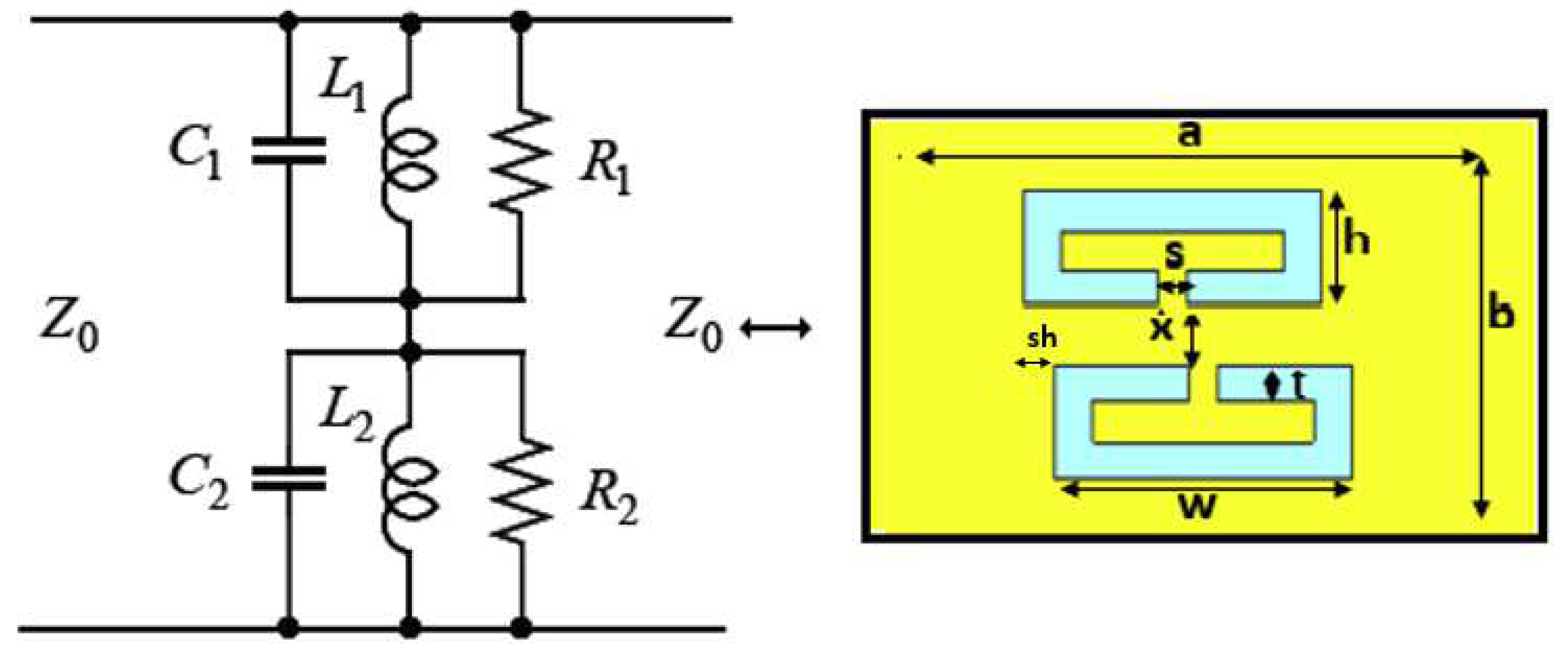
3.1. Bandpass Waveguide Filter Using Symmetric CSRR
4. Discussion
5. Conclusions
Author Contributions
Funding
Conflicts of Interest
Abbreviations
| MM | Metamaterial |
| SRR | Split Ring Resonator |
| CSRR | Complementary Split Ring Resonator |
| CST | Computer Simulation Technology |
References
- Pozar, D.M. Microwave Engineering; Wiley: Hoboken, NJ, USA, 2012. [Google Scholar]
- Guo, C.; Shang, X.; Lancaster, M.J.; Xu, J. A 3D printed lightweight X-band waveguide filter based on spherical resonators. IEEE Microw. Wirel. Compon. Lett. 2015, 25, 442–444. [Google Scholar] [CrossRef]
- Atia, A.E.; Williams, A.E. Narrow-bandpass waveguide filters. IEEE Trans. Microw. Theory Tech. 1972, 20, 258–265. [Google Scholar] [CrossRef]
- Bonetti, R.R.; Williams, A.E. Application of dual TM modesto triple-and quadruple-mode filters. IEEE Trans. Microw. Theory Tech. 1987, 35, 1143–1149. [Google Scholar] [CrossRef]
- Levy, R.; Cohn, S.B. A history of microwave filter research, design, and development. IEEE Trans. Microw. Theory Tech. 1984, 32, 1055–1067. [Google Scholar] [CrossRef]
- Levy, R.; Snyder, R.V.; Matthaei, G. Design of microwave filters. IEEE Trans. Microw. Theory Tech. 2002, 50, 783–793. [Google Scholar] [CrossRef]
- Hunter, I.C.; Billonet, L.; Jarry, B.; Guillon, P. Microwave filters-applications and technology. IEEE Trans. Microw. Theory Tech. 2002, 50, 794–805. [Google Scholar] [CrossRef]
- Zou, X.; Tong, C.M.; Yu, D.W. Design of an X-band symmetrical window bandpass filter based on substrate integrated waveguide. In Proceedings of the 2011 Cross Strait Quad-Regional Radio Science and Wireless Technology Conference, Harbin, China, 26–30 July 2011; Volume 1, pp. 571–574. [Google Scholar]
- Damou, M.; Nouri, K.; Feham, M.; Chetioui, M. Design and Optimization of Rectangular Waveguide Filter based on Direct Coupled Resonators. Int. J. Electron. Telecommun. 2017, 63, 375–380. [Google Scholar] [CrossRef]
- Morelli, M.; Hunter, I.; Parry, R.; Postoyalko, V. Stopband performance improvement of rectangular waveguide filters using stepped-impedance resonators. IEEE Trans. Microw. Theory Tech. 2002, 50, 1657–1664. [Google Scholar] [CrossRef]
- Liao, S.S.; Sun, P.T.; Chen, H.K.; Liao, X.Y. Compact-size coplanar waveguide bandpass filter. IEEE Microw. Wirel. Compon. Lett. 2003, 13, 241–243. [Google Scholar] [CrossRef]
- Goussetis, G.; Budimir, D. Novel periodically loaded E-plane filters. IEEE Microw. Wirel. Compon. Lett. 2003, 13, 193–195. [Google Scholar] [CrossRef]
- Mohottige, N.; Glubokov, O.; Jankovic, U.; Budimir, D. Ultra Compact Inline E-Plane Waveguide Bandpass Filters Using Cross Coupling. IEEE Trans. Microw. Theory Tech. 2016, 64, 2561–2571. [Google Scholar] [CrossRef]
- Mohottige, N.; Glubokov, O.; Budimir, D. Ultra Compact Inline E-Plane Waveguide Extracted Pole Bandpass Filters. IEEE Microw. Wirel. Compon. Lett. 2013, 23, 409–411. [Google Scholar] [CrossRef]
- Budimir, D.; Glubokov, O.; Potrebić, M. Waveguide filters using T-shaped resonators. Electron. Lett. 2011, 47, 38–40. [Google Scholar] [CrossRef]
- Chen, X.P.; Wu, K. Substrate integrated waveguide filters: Design techniques and structure innovations. IEEE Microw. Mag. 2014, 15, 121–133. [Google Scholar] [CrossRef]
- Zhou, S.; Wang, Z.; Xu, R.; Shen, D.; Zhan, M. A novel X-band half mode substrate integrated waveguide (HMSIW) bandpass filter. In Proceedings of the 2009 Asia Pacific Microwave Conference, Singapore, 7–10 December 2009; pp. 1387–1389. [Google Scholar]
- Jin, C.; Chen, J.X.; Chu, H.; Bao, Z.H. X-band differential bandpass filter with high common-mode suppression using substrate integrated waveguide cavity. Electron. Lett. 2014, 50, 88–89. [Google Scholar] [CrossRef]
- Wong, S.W.; Chen, R.S.; Wang, K.; Chen, Z.N.; Chu, Q.X. U-shape slots structure on substrate integrated waveguide for 40-GHz bandpass filter using LTCC technology. IEEE Trans. Compon. Packag. Manuf. Technol. 2015, 5, 128–134. [Google Scholar] [CrossRef]
- Dahle, R.; Laforge, P.; Kuhling, J. 3-D Printed Customizable Inserts for Waveguide Filter Design at X-Band. IEEE Microw. Wirel. Compon. Lett. 2017, 27, 1080–1082. [Google Scholar] [CrossRef]
- Liu, L.; Zhang, P.; Weng, M.H.; Tsai, C.Y.; Yang, R.Y. A Miniaturized Wideband Bandpass Filter Using Quarter-Wavelength Stepped-Impedance Resonators. Electronics 2019, 8, 1540. [Google Scholar] [CrossRef]
- Pendry, J.B.; Holden, A.J.; Robbins, D.J.; Stewart, W. Magnetism from conductors and enhanced nonlinear phenomena. IEEE Trans. Microw. Theory Tech. 1999, 47, 2075–2084. [Google Scholar] [CrossRef]
- Veselago, V. Electrodynamics of substances with simultaneously negative electrical and magnetic permeabilities. Physics-Uspekhi 1968, 10, 504–509. [Google Scholar]
- Hrabar, S.; Bartolic, J.; Sipus, Z. Waveguide miniaturization using uniaxial negative permeability metamaterial. IEEE Trans. Antennas Propag. 2005, 53, 110–119. [Google Scholar] [CrossRef]
- Ortiz, N.; Baena, J.; Beruete, M.; Falcone, F.; Laso, M.; Lopetegi, T.; Marques, R.; Martin, F.; Garcia-Garcia, J.; Sorolla, M. Complementary split-ring resonator for compact waveguide filter design. Microw. Opt. Technol. Lett. 2005, 46, 88–92. [Google Scholar] [CrossRef]
- Stefanovski, S.L.; Potrebić, M.M.; Tošić, D.V. Design and analysis of bandpass waveguide filters using novel complementary split ring resonators. In Proceedings of the 2013 11th International Conference on Telecommunications in Modern Satellite, Cable and Broadcasting Services (TELSIKS), Nis, Serbia, 16–19 October 2013; Volume 1, pp. 257–260. [Google Scholar]
- Fallahzadeh, S.; Bahrami, H.; Tayarani, M. A novel dual-band bandstop waveguide filter using split ring resonators. Prog. Electromagn. Res. 2009, 12, 133–139. [Google Scholar] [CrossRef]
- Fathnan, A.; Amrullah, Y.; Wijayanto, Y.; Mahmudin, D.; Daud, P. A compact X-Band bandpass filter using rectangular split ring resonators for radar applications. In Proceedings of the 2015 International Conference on Radar, Antenna, Microwave, Electronics and Telecommunications (ICRAMET), Bandung, Indonesia, 5–7 October 2015; pp. 60–63. [Google Scholar]
- Odabasi, H.; Teixeira, F. Electric-field-coupled resonators as metamaterial loadings for waveguide miniaturization. J. Appl. Phys. 2013, 114, 214901. [Google Scholar] [CrossRef]
- Bage, A.; Das, S. Stopband Performance Improvement of CSRR-Loaded Waveguide Bandpass Filters Using Asymmetric Slot Structures. IEEE Microw. Wirel. Compon. Lett. 2017, 27, 697–699. [Google Scholar] [CrossRef]
- Torabi, Y.; Dadashzadeh, G.; Oraizi, H. Miniaturized sharp band-pass filter based on complementary electric-LC resonator. Appl. Phys. A 2016, 122, 273. [Google Scholar] [CrossRef]
- Dong, Y.; Itoh, T. Miniaturized dual-band substrate integrated waveguide filters using complementary split-ring resonators. In Proceedings of the 2011 IEEE MTT-S International Microwave Symposium, Baltimore, MD, USA, 5–10 June 2011; pp. 1–4. [Google Scholar]
- ul Haq, T.; Khan, M.; Siddiqui, O. Design and implementation of waveguide bandpass filter using complementary metaresonator. Appl. Phys. A 2016, 122, 34. [Google Scholar] [CrossRef]
- Bahrami, H.; Hakkak, M.; Pirhadi, A. Using complementary split ring resonators (CSRR) to design bandpass waveguide filters. In Proceedings of the 2007 Asia-Pacific Microwave Conference, Bangkok, Thailand, 11–14 December 2007; pp. 1–4. [Google Scholar]
- Yoon, K.C.; Kim, S.C.; Lee, J.C. Compact low noise amplifier with high stable gain using distributed CRLH metamaterial. Microw. Opt. Technol. Lett. 2016, 58, 1715–1720. [Google Scholar] [CrossRef]
- Chen, R.; Li, R.; Zhou, S.; Chen, S.; Huang, J.; Wang, Z. An X-Band 40 W Power Amplifier GaN MMIC Design by Using Equivalent Output Impedance Model. Electronics 2019, 8, 99. [Google Scholar] [CrossRef]
- Hong, J.S.G.; Lancaster, M.J. Microstrip Filters for RF/Microwave Applications; John Wiley & Sons: Hoboken, NJ, USA, 2004; Volume 167. [Google Scholar]
- Shang, X.; Xia, W.; Lancaster, M.J. The design of waveguide filters based on cross-coupled resonators. Microw. Opt. Technol. Lett. 2014, 56, 3–8. [Google Scholar] [CrossRef]


| Parameters | Resonant Frequency | Bandwidth |
|---|---|---|
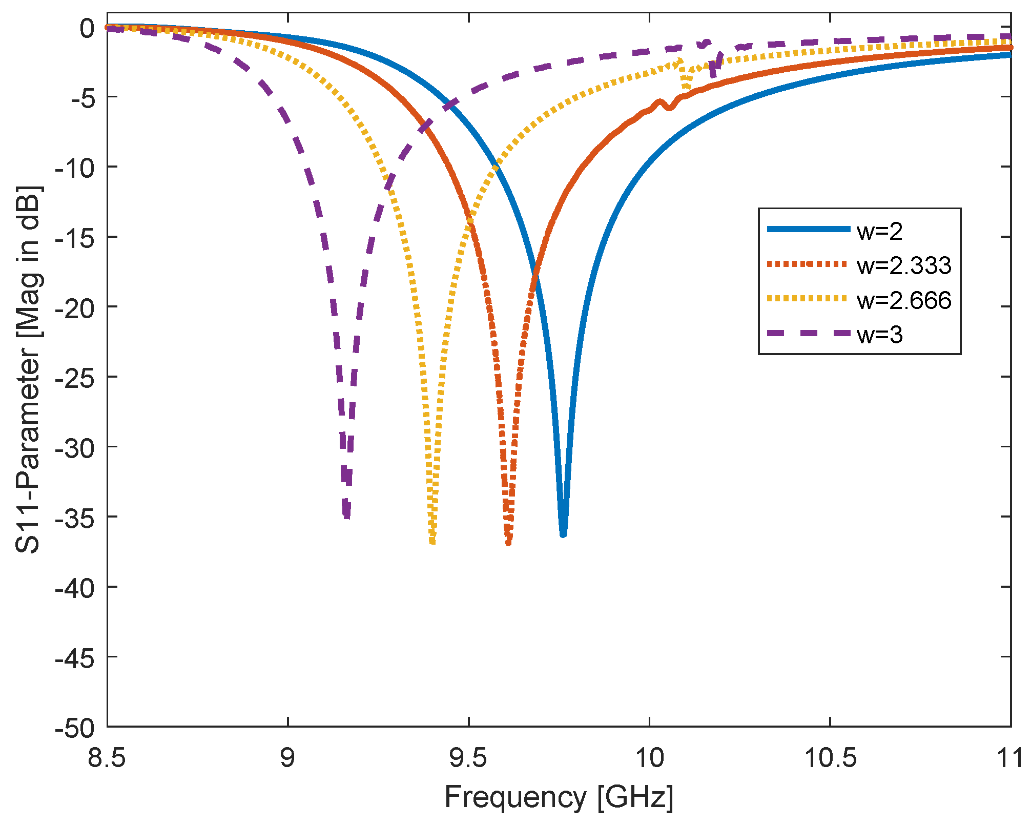
| w ↑ | ← | decreases |
| s ↑ | → | increases |
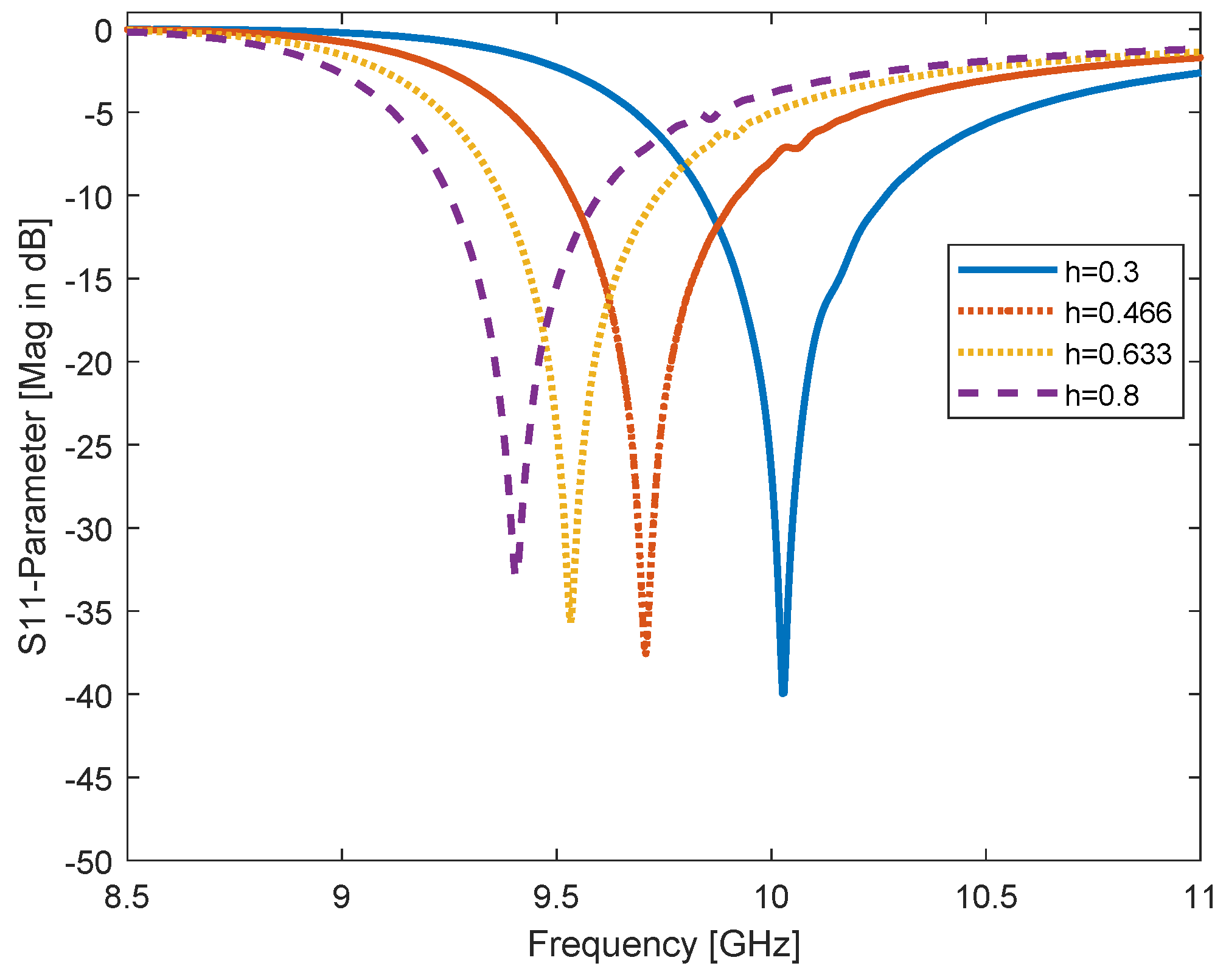
| h ↑ | ← | decreases |
| t ↑ | ≈ | increases |
| x ↑ | ← | decreases |
| sh ↑ | ← | ≈ |
| Filter Type | (GHz) | L (mm) | s11 (dB) | BW (GHz) | |
|---|---|---|---|---|---|
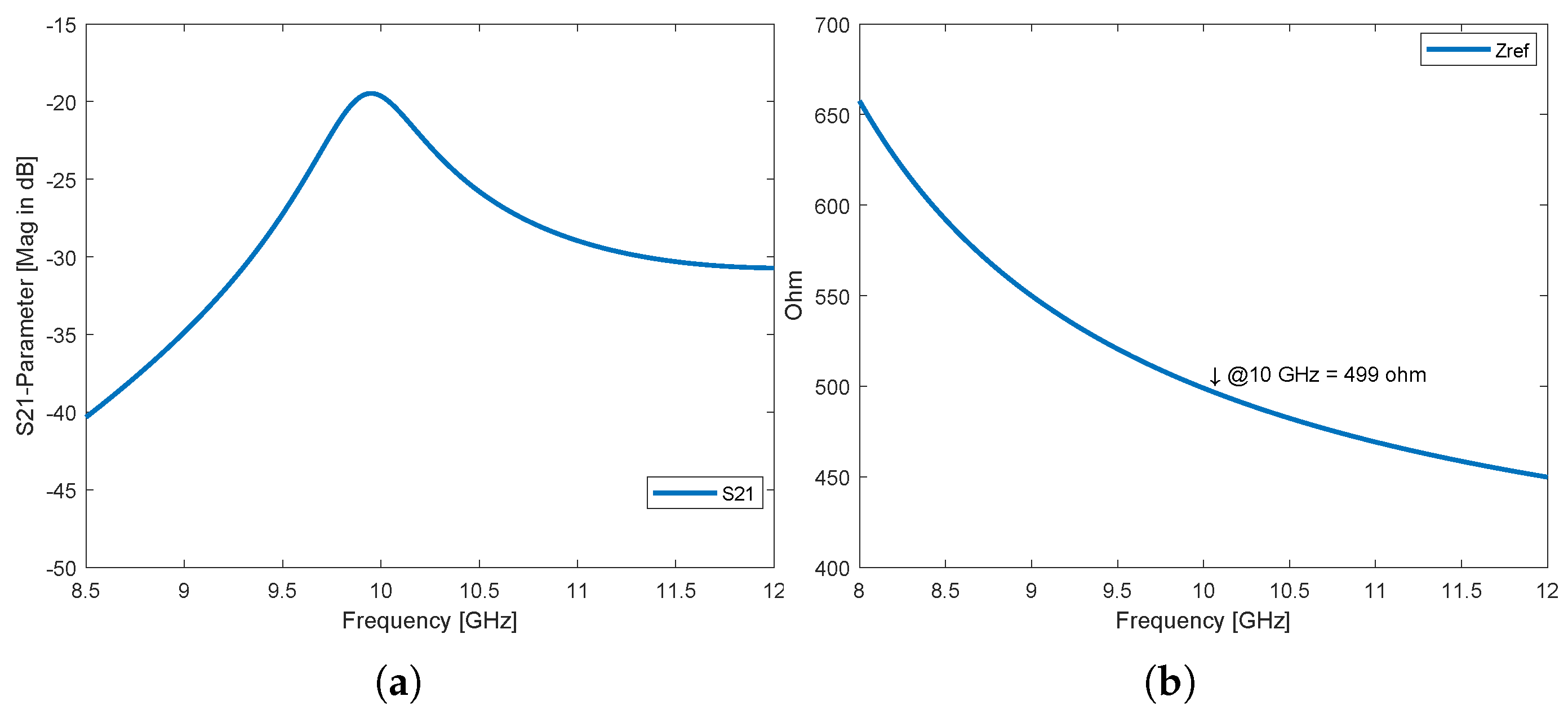
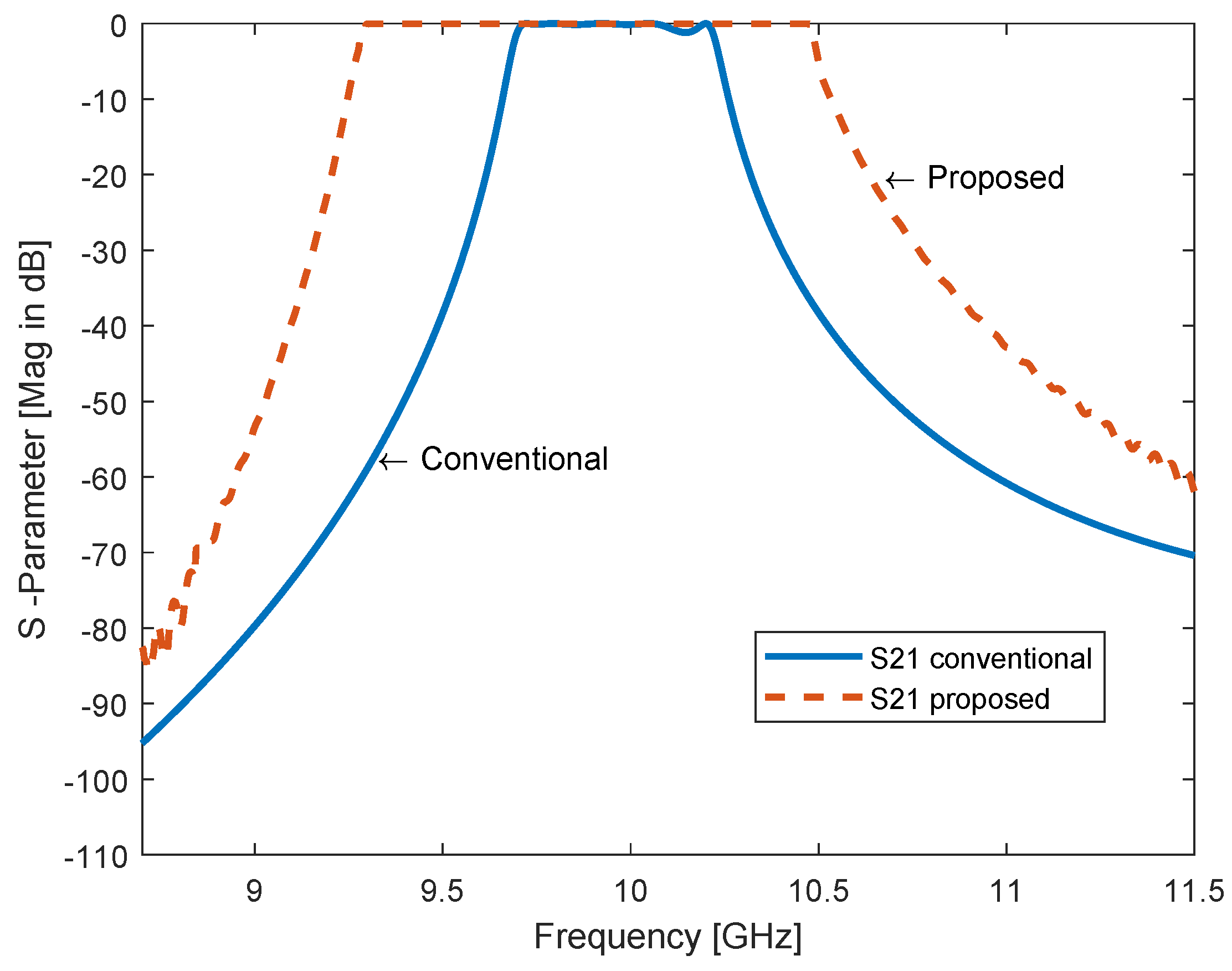
| Proposed filter | 10 | 51 | −20 | 499 | 1.22 |
| Conventional filter | 10 | 97.1 | −19 | 497 | 0.550 |
© 2020 by the authors. Licensee MDPI, Basel, Switzerland. This article is an open access article distributed under the terms and conditions of the Creative Commons Attribution (CC BY) license (http://creativecommons.org/licenses/by/4.0/).
Share and Cite
AbuHussain, M.; Hasar, U.C. Design of X-Bandpass Waveguide Chebyshev Filter Based on CSRR Metamaterial for Telecommunication Systems. Electronics 2020, 9, 101. https://doi.org/10.3390/electronics9010101
AbuHussain M, Hasar UC. Design of X-Bandpass Waveguide Chebyshev Filter Based on CSRR Metamaterial for Telecommunication Systems. Electronics. 2020; 9(1):101. https://doi.org/10.3390/electronics9010101
Chicago/Turabian StyleAbuHussain, Mahmoud, and Ugur C. Hasar. 2020. "Design of X-Bandpass Waveguide Chebyshev Filter Based on CSRR Metamaterial for Telecommunication Systems" Electronics 9, no. 1: 101. https://doi.org/10.3390/electronics9010101
APA StyleAbuHussain, M., & Hasar, U. C. (2020). Design of X-Bandpass Waveguide Chebyshev Filter Based on CSRR Metamaterial for Telecommunication Systems. Electronics, 9(1), 101. https://doi.org/10.3390/electronics9010101