Abstract
As one of the most important and computationally-intensive parts in bioinformatics analysis, the Pair Hidden Markov Model (Pair-HMM) forward algorithm is widely recognized and has great potential. Therefore, it is important to accelerate the process of this algorithm. There are various approaches to accelerate Pair-HMM, especially the accelerators stemmed from the Field Programmable Gate Array (FPGA) due to the highly-customizable on-chip resources and deep pipeline potential available to the designer. In this paper, we focus on the FPGA-based accelerators for the Pair-HMM forward algorithm proposed in recent years. The non-cooperation structure, which was proposed in our previous work, is compared with the Systolic Array (SA) structure and PE ring structure in the structure characteristics, calculation mode, computational efficiency, and storage requirement. We build an analysis model to evaluate the performance of the ring structure and our non-cooperative structure. Furthermore, based on this, we provide a detailed analysis of the characteristics of structures of different accelerators and of the selection of a suitable structure for different scenarios. Based on the non-cooperative PE structure, we design a new chain topology for the accelerator. Experimental results show that our non-cooperation structure is superior to the other structures in performance and execution efficiency, and our new topology improves the performance of the accelerator. Finally, we propose some ideas about the improvement of the non-cooperative structure accelerator for future work.
1. Introduction
Gene sequence alignment is a process that compares the target sequence of DNA, RNA, or a protein with the reference sequence and obtains the similarity between the two gene sequences [1]. This technology is widely applied in the process of screening for disease-causing mutation carriers [2,3,4], early-stage cancer detection [5,6], etc. In a typical gene alignment problem [7], the Pair Hidden Markov Model (Pair-HMM) is most commonly used to evaluate the overall likelihood of any possible alignments between two sequences. The forward algorithm in Pair-HMM is used in the variant calling [8,9] stage in GATK HaplotypeCaller [10].
The execution of the gene sequence alignment needs intensive floating-point operations. Therefore, parallel approaches such as multi-core Central Processing Units (CPUs) [11,12], Graphics Processing Units (GPUs) [13,14], and Field Programmable Gate Arrays (FPGAs) [15,16,17,18,19,20] are used to improve the calculation speed. Compared with CPU and GPU, FPGA has sufficient computational and storage resources and can customize the hardware according to the requirements, especially for computationally-intensive applications. Therefore, FPGAs are suitable for the alignment of the genome sequence and supply a higher performance power ratio.
The Systolic Array (SA) is a parallel architecture that can be applied to a wide range of problems in a modular manner to simplify the design complexity. For the design of FPGA-based Pair-HMM forward algorithm accelerators, the one-dimensional SA [17,21,22] is a common approach and has some improved variants. The main structure of the SA is a pipeline, where the data flow among the Processing Elements (PEs). These PEs are integrated as an array and calculate in sequence alignment simultaneously. However, the SA structure will provoke the waiting and idleness of the PE while calculating.
To overcome its shortcomings, a PE ring structure was proposed in [18,19]. Through one internal buffer, it connects the first and the last PE in one SA. Thus, it provides high effectiveness and decreases the idleness generated by sequences with different lengths. At the same time, the extra idleness also happens when the PE ring structure accelerator is working, especially with the condition that the lengths of sequences fed in the pipeline of one PE ring are different.
Both the SA structure and the PE ring structure are designed for the improvement of the throughput. Nevertheless, the challenges of a large number of alignment programs and different sizes of sequences put forward different methods to solve this problem. Considering the need for throughput and performance while dealing with gene sequences with variable sizes, we designed a Pair-HMM forward algorithm accelerator with the non-cooperative PE structure in [20]. In this structure, every PE supplies high computational efficiency for the alignment tasks of gene sequences with different sizes, independently. Beyond the PE layer, the topology of the overall accelerator is the three-layer tree topology, which can balance the load.
Using an analysis model we built to evaluate the performance of these FPGA-based accelerators, we provide a detailed analysis of the characteristics of the structures of different accelerators. To be specific, the calculation mode, computational efficiency, and storage requirement among the non-cooperative structure, the SA structure, and the PE ring structure are compared. The non-cooperative structure can achieve higher computational efficiency. At the same time, due to the independent control of each PE, it brings the consumption of the resources of the FPGA compared with other structures. Based on this detailed comparison and analysis, we propose a new idea for the topology of the accelerator. We design a chain topology for the overall accelerator, which will reduce the difficulty of layout and the pressure of bandwidth, thus increasing the frequency of the accelerator and improving its performance.
The rest of this paper is organized as follows. Section 2 shows the Pair-HMM forward algorithm. Section 3 shows our analysis model to evaluate the performance of the ring structure and our non-cooperative structure and the design of a new chain topology for the non-cooperative structure accelerator. Section 4 explains the experimental analysis. Section 5 shows the conclusion.
2. Background
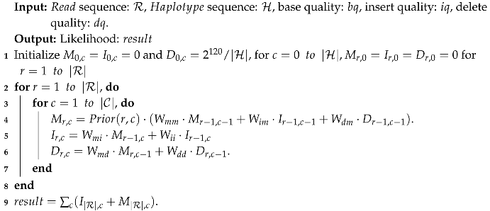
The Pair-HMM forward algorithm is a dynamic programming algorithm with a double-nested loop for calculating the matching probability [22] of a pair of gene sequences under observations consisting of the target and the reference sequence, namely the and the . There are three hidden states in Pair-HMM, namely Match (M), Delete (D), and Insert (I). The probability-based transitions among the three hidden states are shown in Figure 1. Each parameter attached to the red line denotes the transition probability from state x to state y. For convenience, here, we denote the values of state M by , which demonstrates the likelihood of every approach originating from the first element of the sequence to the element in the M state. and are denoted in the same way. The complete Pair-HMM forward algorithm applied in the variant calling analysis tool named GATK HaplotypeCaller [23] is shown as follows in Algorithm 1.
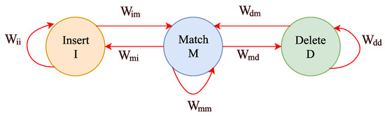
Figure 1.
The diagram of hidden state transitions in the pair hidden Markov model.
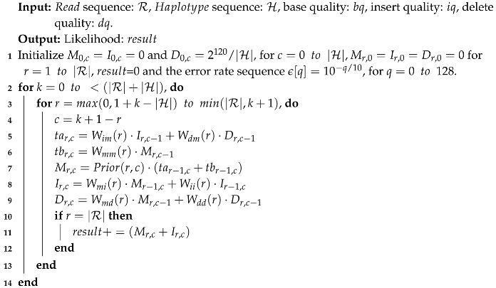
As shown in Algorithm 1, the maximum length of the critical paths for calculating is longer than that for calculating and . In the field of FPGA, this imbalance leads to the idleness of hardware. Proposed in [19], two auxiliary variables, named and , are added into the recursion, which calculate partial calculations of in advance, to achieve unifying the lengths of the critical paths. Therefore, while implementing this optimized algorithm, the cost of the memory resources will increase accordingly. On this basis, the optimized Pair-HMM forward algorithm used in [20] is shown in Algorithm 2 and the following.
| Algorithm 1: Pseudocode for the Pair-HMM forward algorithm. |
 |
| Algorithm 2: Pseudocode for the optimized Pair-HMM forward algorithm. |
 |
The sequence, the sequence, and quality factor sequences are the inputs of the Pair-HMM forward algorithm. The intermediate variables of the recursion contain M, I, D, , and . The output part is the likelihood of all possible alignments between two sequences.
To illustrate the comparative analysis of FPGA-based accelerators, we use two concepts defined in [20].
- Task: The entire computation of the alignment of a pair of sequences.
- Computation matrix: In the task denoted above, the computation matrix indicates the process of computation in which every element of the and the sequences is to be compared. The size of the computation matrix is . The element of the computation matrix, shown as , represents the calculating recursion in Algorithm 2 with the same indices r and c.
For further analysis, we show the characteristics of the algorithm as Figure 2 and the following.
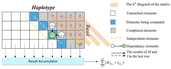
Figure 2.
The features of the Pair-HMM forward algorithm.
- This is a computationally-intensive algorithm. With n and m representing the lengths of the and sequences, respectively, the time complexity is , and the memory complexity is .
- The sequences alignment tasks are independent, which means that there is no data dependence.
- The traversal of Algorithm 2 is performed in a diagonal order. k denotes the diagonal. The element of the computation matrix indicates that the element of the sequence is compared with the element of the sequence. Shown in Algorithm 2, the result is calculated by the sum of all and with all different c.
- The calculations of one element are dependent on the calculations of the two elements that have data dependence with it. For example, the element is relevant to the elements and . Therefore, the calculations of depend on the calculations of and . Thus, among the elements on the same diagonal, there is no data dependence. These elements can be calculated in parallel.
Knowing the algorithm clearly, we can perform the comparison of the accelerators based on this.
3. Comparative Analysis of Accelerator Structures and a Novel Topology for the Non-Cooperative Accelerator
3.1. Structures’ Characteristics
- Systolic array: Typically, the systolic array structure is used to organize multiple PEs, perform a single sequence alignment task collaboratively, and develop instruction-level parallelism. As shown in [13,17,21], this structure has advantages, including a shorter calculation delay for a single alignment task and the convenience of data flowing among the neighbor PEs. However, it has less adaptability for tasks with variable lengths of sequences in the pipeline. It will also generate idleness when the lengths of sequences are different in the pipeline or when partial PEs have finished the calculations of the current row of the computation matrix. With n PEs in the array, the first PE can calculate the new row only after the last PE has finished the calculations of the current calculation row n.
- PE ring structure: The PE ring structure based on the PE array was proposed in [19]. This structure is improved based on the SA structure. It connects the first PE and the last PE with an internal buffer and generates a ring with n PEs. It benefits from sharing data when the first PE changes the current calculation row k to the following calculation row . It improves the adaptability to variable length input, but there are still problems of a high idleness rate. The design of multi-PE collaboration increases the complexity of control.
- Non-cooperative structure: We proposed the non-cooperative PE structure in our previous work [20]. Different from the two mentioned structures, our non-cooperative PE structure has no cooperation among the PEs. Each PE can independently perform a single sequence alignment task. The total accelerator integrates numerous PEs with the three-layer topology architecture. Multiple tasks are processed in parallel independently. Therefore, this PE structure obeys the principle of SPMD (Single Program Multiple Data).
The calculation processes of the three structures are shown in Figure 3. The blue-bordered grids represent the sequence order of the PE processing in the pipeline. The dotted PE blocks in Figure 3a,b represent the situation when calculating the previous element, and the red line represents the direction in which the intermediate results are transmitted. The block, named , indicates the raw data from the element of the sequence and the element of the sequence in the task. The block, named , represents the element of the intermediate result data in the task. Note that the intermediate result data are stored in the shape of a diagonal.
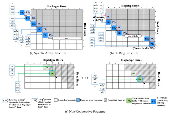
Figure 3.
The calculations of the three structures.
As shown in Figure 3a,b, the SA structure and the PE ring structure are based on the principle that multiple PEs cooperate to process one task. These PEs are used to calculate elements on the same diagonal without data dependence. Multiple tasks are processed sequentially in the pipeline. These two structures seek to meet the real-time requirements of a single task to complete in shorter cycles.
In the SA, data streams synchronously flow through adjacent two-dimensional array elements. It is not flexible enough such that only when all n PEs have completely processed all the elements of the row, it can start calculating the next n rows of elements. As a consequence, it will generate idleness during the calculations.
However, the PE ring structure can directly process the elements of the row after all the elements of row are processed to avoid the idleness generated by the SA while switching the rows.
The non-cooperative structure also pursues the throughput with the pipeline scheme. The calculations of elements on the same diagonal are sequentially sent into the pipeline for processing. When the calculations of the first element in the current diagonal are still waiting to be finished, the data dependence will occur if the data in the adjacent diagonal are still fed. In this situation, idle operations will be inserted.
3.2. Comparative Analysis
Since the PE ring structure surpasses the SA structure in performance, we will only compare the non-cooperative structure with the PE ring in detail. The core difference between these two structures is whether there is any cooperation among PEs. It can be reflected in the smallest repeatable unit, i.e., a ring and the non-cooperative structure with the same number of PEs. On this basis, both the PE ring structure and the non-cooperative structure have coarse-grained parallelism at a higher level. We established a parametric analytical model for these two structures. In the following paragraphs, we will present our analytical model and a comparative analysis of the two structures from three main aspects.
3.2.1. Calculation Mode
The calculation mode of the PE ring structure is shown in Figure 3b. When the PEs calculate elements in the task, the calculation mode is as if they are placed along the diagonal. In the first sweep, the first n rows are calculated. After the first PE reaches the last element of the first row, it can continue to process the row in the computation matrix. All PEs start to process different elements of one task in the same cycle and will start to process the elements in the same position as another task in the next cycle. tasks can be processed in the pipeline simultaneously where represents the pipeline depth of the PE. After the intermediate results of the first task are generated, these intermediate results are passed to its adjacent PE. Then, the next element of the first task will be processed in the next cycle. This procedure is shown in Figure 4a.
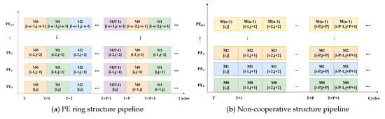
Figure 4.
The pipeline of adjacent PEs’ processing matrix elements of the PE ring and non-cooperative structure.
The calculation mode of the non-cooperative structure is shown in Figure 3c. Each PE processes a single task. Each PE traverses the computation matrix along the diagonals and processes the elements on the diagonal line in turn. Only when the results of the first element of the current diagonal are generated can the calculations in the next diagonal start without waiting. Otherwise, it is necessary to insert idle operations to wait for the calculation to complete and avoid the error. Shown as Figure 4b, we can see that in the non-cooperative structure pipeline, each PE processes the elements of a task in a diagonal order.
3.2.2. Computational Efficiency
Figure 5 shows the computational efficiency of the SA structure, the PE ring structure, and the non-cooperative structure. In addition to the idleness caused in the startup and shutdown phases, the SA also generates a large number of idle cycles while switching the passes. The PE ring structure avoids this idleness while shifting the rows. The non-cooperative structure only generates idleness in the startup and shutdown phases. In these two phases of the task, it is necessary to insert idle operations at the end of the diagonals. This ensures that the calculation of the next diagonal starts only after generating the results of the first element of the current diagonal, which has the data dependence with the first element on the next diagonal. With the condition that the pipeline depth is , for the diagonal, there are idle operations inserted. When , the pipeline can run without any idle operation. Figure 6 shows the specific analysis of idle cycles in the PE ring and non-cooperative structure. Figure 6a,b shows the PE idleness of the PE ring structure in the startup and shutdown phases. Figure 6c,d shows the PE idleness of the non-cooperative structure in the startup and shutdown phases.
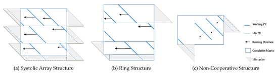
Figure 5.
The computational efficiency of the three structures.
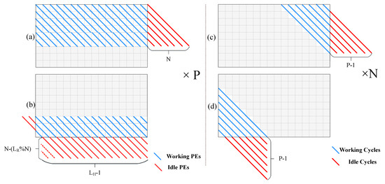
Figure 6.
PE idle cycles in two structures. This figure shows the specific idle cycles in the PE ring and the non-cooperative structure. (a,b) show the PE idleness of the PE ring structure, in the startup and flush phase. (c,d) show the PE idleness of the non-cooperative structure in the startup and the flush phase.
It needs to be noted that the idleness in the shutdown phase in the PE ring structure is related to the length of the sequence. The total idle cycles in the non-cooperative structure maintain a fixed value for variable lengths of sequences. According to Figure 6, when the number of PE is , the length of the sequence is , the length of the sequence is , and the pipeline depth is , we can characterize idle cycles for the PE ring structure as:
For the non-cooperative structure:
The ratio of idle cycles between the PE ring structure and the non-cooperative structure is:
As shown in Figure 7, if the lengths of the sequences calculated in the pipeline on the same ring are different, it will generate extra idle operations.
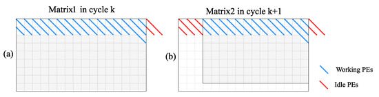
Figure 7.
In the PE ring structure, in the case where the size of the two adjacent matrices on the pipeline are different, the PEs are idle in two adjacent cycles. (a) shows the status of computation matrix for the 1st task in cycle k, and (b) shows the status of computation matrix for the 2nd task in cycle k+1.
In this case, the number of idle cycles of the PE ring structure is shown in (7). After data testing, the ratio of the idle cycles influenced by the length of the sequence in the two situations is shown in Figure 8.
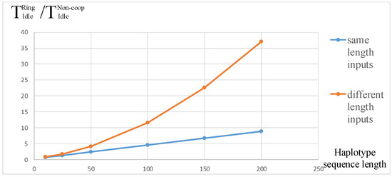
Figure 8.
The ratio of idle cycles with the same or different lengths of input sequences and different .
3.2.3. Storage Requirement
The storage requirement is divided into two parts: five intermediate result variables M, I, D, , and five raw data sequences .
In the PE ring structure, the intermediate results between adjacent PEs can flow without delay, which means that it does not need any extra memory to store the data. Therefore, only the internal buffer after the last PE of the ring stores intermediate results for all pipeline stages. The ring performs multiple tasks with the pipeline, which needs to store intermediate results of multiple tasks, as well. As a result, the storage requirement for the PE ring structure is as follows:
The non-cooperative structure performs one task with one PE, meaning that it needs to store intermediate results of one task. Therefore, the storage requirement is shown as follows:
When the pipeline depth , the PE numbers and ; in this case, .
3.3. Advantages and Disadvantages of the Comparison
By comparing these structures, we can know that the non-cooperative PE structure shows notable differences in calculation mode. This structure shows higher computational efficiency by decreasing the idle cycles while calculating. It also decreases the idleness generated by the cooperation with other PEs. On the other hand, the mode that PE performs independently makes the cost of the control of each PE obviously larger than the SA and the ring structures.
3.4. A Novel Topology for the Non-Cooperative Accelerator
Based on the structure of non-cooperative PE, we originally designed a three-layer tree topology in [20], which is shown in Figure 9. In the top module, the original topology structure transmits data to multiple top-level modules’ allocation by polling, that is the FIFO (First In First Out) corresponding to each allocation is directly connected to the DMA (Direct Memory Access) read engine. The advantage of this design is that it can balance the load of all PEs in this accelerator. However, this architecture results in the design of the layout where wires with a wide width are gathering.
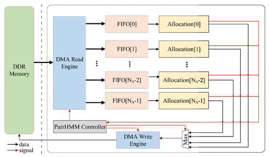
Figure 9.
The accelerator with the tree topology.
After further consideration, we put forward a new idea on the overall topology of the accelerator. We designed a novel chain topology to alleviate this problem and improve the performance. In this way, the difficulty of layout and routing can be further reduced. In our new chain topology, the FIFO corresponding to the first allocation is directly connected with the DMA read engine, while the next FIFOs are connected with the previous one by a buffer, which is shown in Figure 10. We will analyze this from the following aspects.
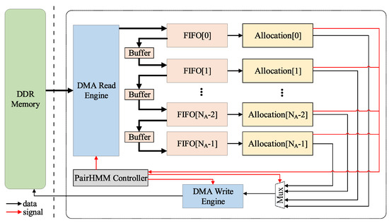
Figure 10.
The accelerator with the chain topology.
- Bandwidth: Consistent with the original tree topology.
- Latency: In the chain topology, when data are transmitted between FIFOs, there will be delay. However, in our design, has a small value of eight. Therefore, the latency added by data transmission is only up to eight cycles. In the pipeline operation mode, the extra performance loss caused by the new topology is negligible compared to the original structure.
- Performance: Because the path bandwidth between the DMA read engine and FIFOs is relatively large, if the original tree topology scheme is adopted, the layout and routing will be under great pressure. The use of the chain topology will reduce the difficulty of layout and routing, thus increasing the operating frequency of the accelerator and improving its performance.
- Scheme mode: It is assumed that i is a PE index for judging whether or not data are allocated, and the initial value is zero. Each allocation will generate a FULL signal to indicate whether the PEs inside the allocation are already full of data being calculated. If the FULL signal of Allocation[i] is FALSE, the data will be sent to Allocation[i], and . If the FULL signal of Allocation[i] is TRUE, the data will not be transmitted, and , and so on. This can better balance the load. All signals generated by allocation are processed centrally by the controller. The data transfer is done through the buffer to the next allocation. The structure and scheme of the allocation module have not changed.
4. Experiments Analysis
The test data for our comparison were one dataset from the Whole Genome Sequence [24]. This dataset includes three datasets, named “tiny”, “10s”, and “1m”, of which the length of sequences ranges from 10–302.
Table 1 shows the performance comparison among implementations in various platforms, which included multi-core CPU, GPU, and FPGA. The middle-scale dataset, named “10s”, was used as the test dataset for the comparison. In the Altera Arria 10, there were 128 PEs integrated both in [19,20]. The performance of the non-cooperative structure was 1.19 × higher than the average factor of the PE ring structure as a result of fewer idle cycles and easier load balancing among PEs for different lengths of - pairs on the real-world dataset.

Table 1.
Comparison of the performance of different implementations.
The resource utilization and frequency results in the ring structure and the non-cooperative structure implemented on FPGAs from [19,20] are shown in Table 2. From the perspective of implementation, the storage requirements of the two structures were not the bottleneck limiting computational resources. Considering the settings of parameters, there were subtle differences in [20] and [19] between the Pair-HMM forward algorithms. Compared with the algorithm in [19], one extra floating-point multiplication operation was added into the calculations of the “Prior” parameter in [20]. This resulted in a higher computational resource utilization for a single PE than [19].
Table 2.
Utilization for target FPGAs [19,20].
However, the control mode of the ring structure is that the ring composed of multiple PEs uses one controller, while the control mode of the non-cooperative structure is that each PE has an independent controller. With a large number of PEs integrated together, the pipeline control module of all PEs in non-cooperative structure will occupy more LUT resources. For those FPGAs with less DSP resources or unbalanced resources, such as Stratix V, the non-cooperative accelerator is not recommended. Generally speaking, because floating-point computation in the algorithm cannot be implemented entirely by DSP, a considerable amount of LUT resources are used to implement floating-point computation, so there are resource bottlenecks in the implementation of the overall accelerator, that is to say, the same number of PEs cannot be achieved. In this case, the ring structure is better.
For FPGAs with more balanced resources of DSP and LUT, such as Altera’s Arria 10 and Xilinx’s XC7VX485T, the non-cooperative structure can show its performance advantages better.
The non-cooperative structure has flexibility while computing a large number of sequence alignment tasks to avoid redundancy in collaborative computing. However, it also means more precise control, which brings more resource consumption. We think that the problem that the non-cooperative structure consumes too much computational resources at present can be optimized and reduced through further implementation design so that it can be better applied in more FPGAs.
Table 3 shows the comparison of the runtime and effective cycle ratio in three implementations. The runtime information shows the actual performance of the accelerator, which is affected by the FPGA frequency. The effective cycle rate shows the ratio of the theoretically effective calculation cycles to the actual consumption cycles of the accelerator based on the analytical model we established. We can see that the accelerator of the non-cooperative 64 PEs version was the most efficient and had significant advantages over the ring structure accelerator with the same number of PEs. At the same time, under the same accelerator structure, the 64 PE version was slightly more efficient than the 128 PE version. After our analysis, this was because, in the accelerator of the 128 PE version, the number of PEs that were controlled by the same controller to poll the computing task was more than the accelerator of the 64 PE version, which led to greater delay.
Table 3.
Comparison of the runtime and effective cycle ratio of different implementations in the three test datasets.
As for the design of the chain topology of the non-cooperative PE accelerator, we implemented it on Xilinx’s XC7VX485T. In Table 1 and Table 2, we show the performance and the utilization of the chain topology accelerator. We can see that, compared to the tree topology scheme proposed in [20], our new chain topology improved the frequency of the accelerator and the performance with the same FPGA.
5. Conclusions and Future Works
In this paper, we compared three structures of the FPGA-based Pair-HMM forward algorithm accelerators, including the SA structure, the ring structure, and our non-cooperative structure.
We built a parametric model to analyze the differences among the structures from the aspects of the calculation mode, the computational efficiency, and the storage requirement. Regarding FPGAs equipped with different computational hardware, these structures can be flexibly ported, improve their applicability, and maximize computational resources’ utilization for the best performance. The non-cooperative structure had considerable differences compared to the SA structure and the PE ring structure in the calculation mode and organized schemes. The largest difference was that the data would not flow among PEs, while in the SA structure and the PE ring structure, data flow in every PE sub-structure. In other words, the non-cooperative structure revealed higher computational efficiency and flexibility than other FPGA-based implementations with different structures. However, this flexibility also brought a large amount of cost with respect to the control components. For those FPGAs with limited resources, the non-cooperative accelerator is not recommended, and the ring structure is better. For FPGAs with more balanced resources of DSP and LUT, the non-cooperative structure can shows its performance advantages better.
For the non-cooperative structure accelerator, we designed a new chain topology. It simplified the complexity of layout and routing and improved the performance by about 4%.
Aiming at the defects of the current structures of accelerators, we will perform further research to improve the performance. As our further work, we propose some ideas. Firstly, with further optimization approaches to decreasing the consumption of the resources of controller components, our FPGA-based accelerator can achieve higher performance. Secondly, according to the characteristics of the sequence alignment task, we are going to research the cooperative controller of mini-batch input data with the same sequence length, which will also decrease the consumption of the resources. Thirdly, the flexible configuration of process units on the basis of a specific FPGA with limited resources may be another important part of our further research. Fourthly, we will use the chain topology to reconstruct the connection of PEs. These ideas of the structure of the accelerator can be applied in the acceleration of other algorithms.
Author Contributions
Conceptualization, Y.D.; funding acquisition, Y.D.; methodology, Y.L.; software, P.W.; writing, original draft, P.W.; writing, review and editing, Y.L. and Y.D..
Funding
This work is supported by the National Key Research and Development Program of China under No. 2018YFB1003405.
Conflicts of Interest
The authors declare no conflict of interest.
Abbreviations
The following abbreviations are used in this manuscript:
| Pair-HMM | Pair Hidden Markov Model |
| FPGA | Field Programmable Gate Array |
| CPU | Central Processing Unit |
| GPU | Graphics Processing Unit |
| PE | Processing Element |
| DNA | Deoxyribonucleic Acid |
| RNA | Ribonucleic Acid |
| DSP | Digital Signal Processor |
| GATK | Genome Analysis Toolkit |
| SA | Systolic Array |
| SPMD | Single Program Multiple Data |
| FIFO | First In First Out |
| DMA | Direct Memory Access |
References
- Wu, L.; Bruns-Smith, D.; Nothaft, F.A.; Huang, Q.; Karandikar, S.; Le, J.; Lin, A.; Mao, H.; Sweeney, B.; Asanović, K.; et al. FPGA Accelerated INDEL Realignment in the Cloud. In Proceedings of the 2019 IEEE International Symposium on High Performance Computer Architecture (HPCA), Washington, DC, USA, 16–20 February 2019; pp. 277–290. [Google Scholar]
- Khoury, M.J.; McCabe, L.L.; McCabe, E.R. Population screening in the age of genomic medicine. N. Engl. J. Med. 2003, 348, 50–58. [Google Scholar] [CrossRef] [PubMed]
- Juengst, E.T. “Prevention” and the goals of genetic medicine. Hum. Gene Ther. 1995, 6, 1595–1605. [Google Scholar] [CrossRef] [PubMed]
- Hill, B.; Smith, J.; Srinivasa, G.; Sonmez, K.; Sirasao, A.; Gupta, A.; Mukherjee, M. Precision medicine and FPGA technology: Challenges and opportunities. In Proceedings of the 2017 IEEE 60th International Midwest Symposium on Circuits and Systems (MWSCAS), Boston, MA, USA, 6–9 August 2017; pp. 655–658. [Google Scholar]
- Rastghalam, R.; Pourghassem, H. Breast cancer detection using MRF-based probable texture feature and decision-level fusion-based classification using HMM on thermography images. Pattern Recognit. 2016, 51, 176–186. [Google Scholar] [CrossRef]
- Llobet, R.; Pérez-Cortés, J.C.; Toselli, A.H.; Juan, A. Computer-aided detection of prostate cancer. Int. J. Med. Inform. 2007, 76, 547–556. [Google Scholar] [CrossRef] [PubMed]
- Shendure, J.; Ji, H. Next-generation DNA sequencing. Nat. Biotechnol. 2008, 26, 1135. [Google Scholar] [CrossRef] [PubMed]
- Cornish, A.; Guda, C. A comparison of variant calling pipelines using genome in a bottle as a reference. BioMed Res. Int. 2015, 2015, 456479. [Google Scholar] [CrossRef] [PubMed]
- Sandmann, S.; De Graaf, A.O.; Karimi, M.; Van Der Reijden, B.A.; Hellström-Lindberg, E.; Jansen, J.H.; Dugas, M. Evaluating variant calling tools for non-matched next-generation sequencing data. Sci. Rep. 2017, 7, 43169. [Google Scholar] [CrossRef] [PubMed]
- McKenna, A.; Hanna, M.; Banks, E.; Sivachenko, A.; Cibulskis, K.; Kernytsky, A.; Garimella, K.; Altshuler, D.; Gabriel, S.; Daly, M. The Genome Analysis Toolkit: a MapReduce framework for analyzing next-generation DNA sequencing data. Genome Res. 2010, 20, 1297–1303. [Google Scholar] [CrossRef] [PubMed]
- Carneiro, M. Accelerating Variant Calling; Broad Institute: Cambridge, UK, 2013. [Google Scholar]
- Speed Up HaplotypeCaller on IBM POWER8 Systems. Available online: https://gatkforums.broadinstitute.org/gatk/discussion/4833/speed-up-haplotypecaller-on-ibm-power8-systems (accessed on 6 June 2019).
- Ren, S.; Bertel, K.; Al-Ars, Z. Exploration of alternative GPU implementations of the pair-HMMs forward algorithm. In Proceedings of the 2016 IEEE International Conference on Bioinformatics and Biomedicine (BIBM), Shenzhen, China, 15–18 December 2016; pp. 902–909. [Google Scholar]
- Ren, S.; Bertels, K.; Al-Ars, Z. Efficient acceleration of the pair-hmms forward algorithm for gatk haplotypecaller on graphics processing units. Evol. Bioinform. 2018, 14, 1176934318760543. [Google Scholar] [CrossRef] [PubMed]
- Sampietro, D.; Crippa, C.; Di Tucci, L.; Del Sozzo, E.; Santambrogio, M.D. FPGA-based PairHMM Forward Algorithm for DNA Variant Calling. In Proceedings of the 2018 IEEE 29th International Conference on Application-Specific Systems, Architectures and Processors (ASAP), Milan, Italy, 10–12 July 2018; pp. 1–8. [Google Scholar]
- Banerjee, S.S.; El-Hadedy, M.; Tan, C.Y.; Kalbarczyk, Z.T.; Lumetta, S.; Iyer, R.K. On accelerating pair-HMM computations in programmable hardware. In Proceedings of the 2017 27th International Conference on Field Programmable Logic and Applications (FPL), Ghent, Belgium, 4–8 September 2017; pp. 1–8. [Google Scholar]
- Peltenburg, J.; Ren, S.; Al-Ars, Z. Maximizing systolic array efficiency to accelerate the PairHMM Forward Algorithm. In Proceedings of the IEEE International Conference on Bioinformatics & Biomedicine, Shenzhen, China, 15–18 December 2016. [Google Scholar]
- Manikandan, G.J.; Huang, S.; Rupnow, K.; Hwu, W.M.W.; Chen, D. Acceleration of the Pair-HMM Algorithm for DNA Variant Calling. In Proceedings of the 2016 IEEE 24th Annual International Symposium on Field-Programmable Custom Computing Machines (FCCM), Washington, DC, USA, 1–3 May 2016. [Google Scholar] [CrossRef]
- Huang, S. Hardware acceleration of the pair HMM algorithm for DNA variant calling. In Proceedings of the IEEE International Symposium on Field-programmable Custom Computing Machines, Washington, DC, USA, 1–3 May 2017. [Google Scholar]
- Wang, P.; Lei, Y.; Dou, Y. Pair-HMM Accelerator Based on Non-cooperative Structure. IEICE Electron. Express 2019, 16, 20190402. [Google Scholar] [CrossRef]
- Ren, S.; Sima, V.M.; Al-Ars, Z. FPGA acceleration of the pair-HMMs forward algorithm for DNA sequence analysis. In Proceedings of the IEEE International Conference on Bioinformatics & Biomedicine, Washington, DC, USA, 9–12 November 2015. [Google Scholar]
- Ito, M.; Ohara, M. A power-efficient FPGA accelerator: Systolic array with cache-coherent interface for pair-HMM algorithm. In Proceedings of the 2016 IEEE Symposium in Low-Power and High-Speed Chips (COOL CHIPS XIX), Yokohama, Japan, 20–22 April 2011; pp. 1–3. [Google Scholar]
- Pair Hmm Overview. Available online: https://github.com/broadinstitute/gatk/blob/master/docs/pair_hmm.pdf (accessed on 12 May 2019).
- Test Data. Available online: https://github.com/MauricioCarneiro/PairHMM/tree/master/test_data (accessed on 12 May 2019).
© 2019 by the authors. Licensee MDPI, Basel, Switzerland. This article is an open access article distributed under the terms and conditions of the Creative Commons Attribution (CC BY) license (http://creativecommons.org/licenses/by/4.0/).