Article

Triple Notches Bandstop Microstrip Filter Based on Archimedean Spiral Electromagnetic Bandgap Structure

1
College of Information and Communication Engineering, Harbin Engineering University, Harbin 150001, China
2
College of Electrical Engineering, Northeast Electric Power University, Jilin 132012, China
*
Author to whom correspondence should be addressed.
Electronics 2019, 8(9), 964; https://doi.org/10.3390/electronics8090964
Submission received: 25 June 2019 / Revised: 30 July 2019 / Accepted: 12 August 2019 / Published: 30 August 2019
(This article belongs to the Special Issue Electromagnetic Scattering Theory and Its Applications)

Abstract

:
With the development of artificial electromagnetic structures, defective grounding structures (DGS), defective microstrip structures (DMS), and electromagnetic bandgap (EBG) have been widely used in the design of microstrip filters. In this paper, a triple notches ultra wideband bandstop microstrip filter based on Archimedean spiral electromagnetic bandgap structure (ASEBG) structure is proposed. Firstly, the equivalent circuit of ASEBG is analyzed, and L and C values are extracted by using Advanced Design System (ADS). Secondly, the correctness of the lumped parameter model is verified by comparing the High Frequency Structure Simulator (HFSS) simulation results with the measured results. Finally, the influence of ASEBG structure parameters on resonant performance is analyzed by HFSS simulation, and the filter parameters are further optimized. By coupling ASEBG structure to existing double notch microstrip filters, a triple notches ultra wideband bandstop microstrip filter is realized. This method can also be used in the design of other microstrip devices with stopband characteristics. The three bandgap center frequencies of the proposed triple notches ultra wideband bandstop microstrip filter are 3.5, 5.2, and 7.4 GHz, respectively. The corresponding maximum attenuation of the three stopbands is 33.6, 24.8, and 21.7 dB, respectively.

1. Introduction

With the development of artificial electromagnetic structures such as electromagnetic bandgap structure and defective microstrip structure, which are widely used in the design of microstrip antennas, microstrip filters, microstrip couplers, and other RF devices. The ultra wide band (UWB) approved by the Federal Communications Commission (FCC) is 3.1–10.6 GHz [1]. It covers narrowband communication systems such as WIMAX band (3.3–3.7 GHz), WLAN band (5.15–5.35 GHz and 5.725–5.825 GHz) and C band (7.25–7.75 GHz). In order to filter the interference of a multi-narrowband system whose transmitting power is obviously higher than UWB, the design of multi-notch microstrip band-stop filter has become a research focus. Generally speaking, artificial electromagnetic structures generally include defective ground structure (DGS), defective microstrip structure (DMS), electromagnetic bandgap structure (EBG) and so on. So far, scholars have applied artificial electromagnetic structures to the design of microstrip filters. The traditional methods to realize notch microstrip filters such as using open or short stub loaded resonators [2,3]; using stepped impedance resonators [4,5]; using multimode resonators [6,7,8] such as T shaped resonators [9,10,11], E shaped resonators [12,13], ring resonators [14], Hilbert-Fork Resonators [15]; coupling resonators are designed by coupling structure between microstrips [16,17]. In addition, microstrip notch filters can be realized by constructing a defective grounding structure (DGS) [18,19]. The defective grounding structure changes the distribution inductance and capacitance of the transmission line by etching the structure on the grounding metal plate, and obtains band-stop and slow-wave characteristics, but it leaks floor energy. In order to solve the problem of floor energy leakage, a defective microstrip structure is proposed. [20,21], which can also generate slow wave characteristics. In [22], the authors proposed a microstrip notch filter based on electromagnetic bandgap structure, which realized a high rejection broadband filter. At present, the realization of UWB tri-notch band-stop filters mainly focuses on the following aspects: a stub loaded resonator [23], square ring short stub loaded resonators [24], a stepped impedance resonator (SIR) [25], a coupled-line sub-loaded shorted stepped impedance resonator (SIR) [26], multiple resonant and defected ground structure [27], hexagonal metamaterials split ring resonators [28], the wave cancellation technique [29], using cascaded and multi-armed methods [30], using controlled coupling of open-loop-ring defected ground structure [31], using the U-resonator and suspended multilayer-technique [32], using the multilayer technique and coupled octagonal defected ground structure [33]. Most methods for designing triple notches bandstop microstrip filters mentioned above are based on a single resonant structure, and the 3 dB bandwidth of the stopband are narrow for filtering narrow-band interference.
In this paper, a triple notches bandstop microstrip filter based on Archimedean spiral EBG structure and existing dual notch microstrip filter is presented. By analyzing the lumped circuit model of Archimedean spiral EBG structure, the lumped parameter model of triple notches bandstop microstrip filter coupled with Archimedean spiral EBG structure is analyzed. The validity of the model is further verified by comparing the actual measurement results of the filter with the simulation results by using Advanced Design System (ADS) software (Agilent Technologies Inc., KSanta Clara, CA, USA) and High Frequency Structure Simulator (HFSS) software (ANSYS, Inc., Canonsburg, PA, USA). Without changing the existing dual notch filter structure, the proposed filter achieves the third stop band by coupling the ASEBG structure on the realized dual notch filter [9].

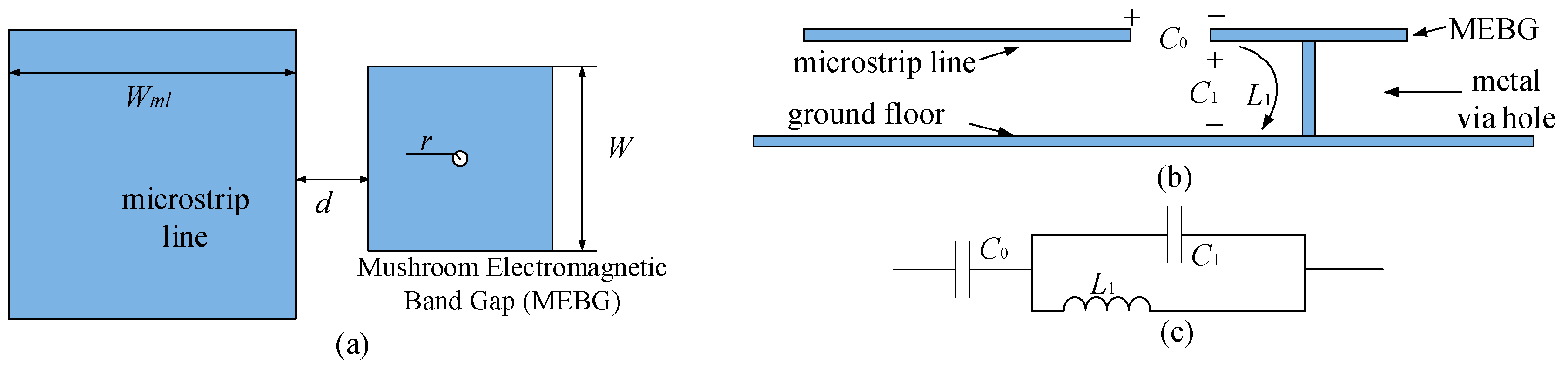
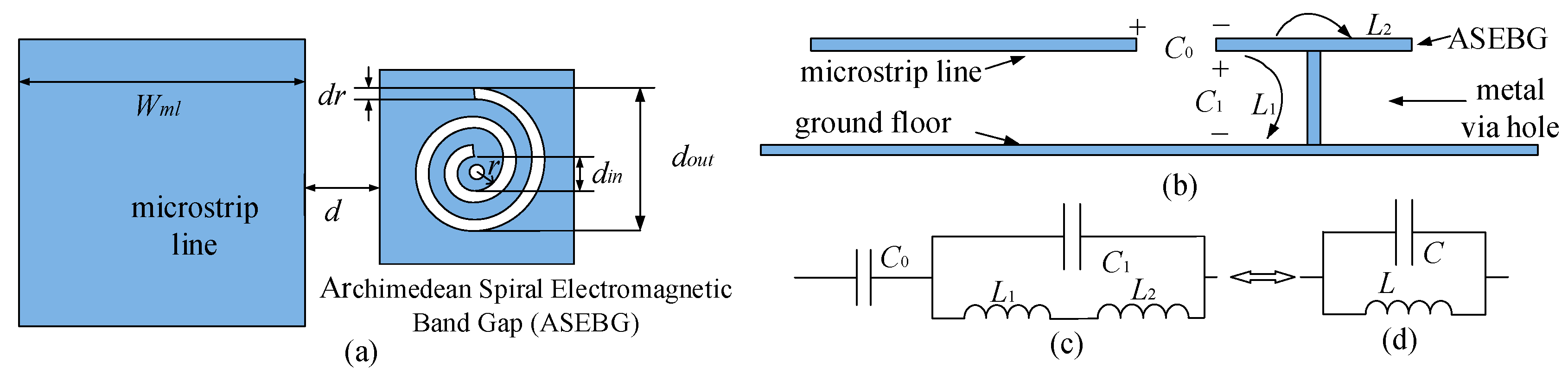
2. Performance Analysis of Archimedean Spiral EBG Structure

2.1. Structural Dimensions

Figure 1a,b shows the top and side views of mushroom electromagnetic band gap (MEBG) structure, respectively. The equivalent circuit diagram of MEBG is shown in Figure 1c. There is a potential difference between the electromagnetic bandgap structure and the microstrip line and the contact floor. C0 is the capacitance between the feeder and the EBG patch. C1 is the capacitance between the EBG patch and the ground plate. L1 is the inductance value on the metal hole.
L 1 = μ 0 2 π [ h ln ( h + r 2 + h 2 r ) + 3 2 ( r r 2 + h 2 ) ] ,
C 1 = W ( ε 0 ε r + ε 0 ) π cosh 1 ( W + d d ) , C 0 = ε r ε 0 W 2 h ,
f = 1 2 π L 1 C 1 ,
Z S = 1 j ω C 1 + 1 j ω L 1 = j ω L 1 1 ω 2 L 1 C 1 .
In the above equations, f is the resonant frequency, which is determined by capacitance and inductance. h is the thickness of dielectric substrate. r is the metal hole radius of electromagnetic bandgap structure. W is the edge length of electromagnetic bandgap structure patch. d is the gap between electromagnetic bandgap structure and feeder. ε 0 is the dielectric constant of vacuum medium substrate; ε r is the relative dielectric constant of dielectric substrate; The inductance mainly depends on h and μ r , and the capacitance mainly depends on the side length W and the spacing d.
The size of traditional MEBG resonator is too large. Adding Archimedean spiral inductance to the surface of the EBG unit can reduce the size of the EBG structure. Archimedean spiral equation is as follows:
X ( t ) = ( r + a t ) cos ( t ) ,
Y ( t ) = ( r + a t ) sin ( t ) ,
t = e n d _ t s t a r t _ t .
In which, X(t) is the transverse coordinate of Archimedean spiral; Y(t) is the axis coordinate of Archimedean spiral; t is the extreme angle, the unit is the degree, indicating the total number of degrees of Archimedean spiral rotation; r is the radius, at t = 0 o , the unit is mm; a is Archimedean spiral coefficient, the unit is mm/°, which indicates the increase (or decrease) of polar diameter per 1° rotation start_t is the starting angle of polar angle; end_t is the maximum angle of polar angle.
Figure 2a,b are the top and side views of Archimedean spiral electromagnetic bandgap structure (ASEBG), respectively, in which dr represent the difference between the inner and outer diameters of Archimedean spiral inductors. The equivalent circuit diagram of ASEBG structure and equivalent circuit for calculating resonance frequency are shown in Figure 2c,d. A new inductance L2 is introduced by loading Archimedean spiral on the surface of mushroom-type EBG patch, which is equivalent to the inductance produced by adding Archimedean spiral to the equivalent circuit of traditional mushroom-type EBG.
According to the Wheeler equation [34], the theoretical formula of Archimedean spiral parameters is as follows:
The capacitance between the microstrip and the EBG patch is C0. The capacitance between the EBG structure and the microstrip line and the contact floor is C1. The inductance value on the metal through hole is L1. The inductance produced by helix in EBG structure is L2. N is the number of coils of inductance. K1 and K2 are the coefficients related to layout, and davg is the average of din and dout.
L 2 = m 0 N 2 K 1 d a v g 1 + K 2 r ,
f = 1 2 π L C 1 , L = L 1 + L 2 ,
Z S = 1 j ω C 1 + 1 j ω L = j ω L 1 ω 2 L C 1 ,
d a v g = ( d i n + d o u t ) / 2 , ( d i n = 2 r , d o u t = r + t a ) ,
r = ( d o u t d i n ) / ( d i n + d o u t ) .
In which, ε 0 is the dielectric constant of the vacuum medium substrate. ε r is the relative dielectric constant of the dielectric substrate. h is the thickness of dielectric substrate; f is the resonant frequency (i.e., the stopband frequency center). r1 is the radius of metal through-hole of electromagnetic bandgap structure. W is the edge length of the EBG patch. d is the electromagnetic bandgap structure and feeder spacing. According to Equations (8)–(12), inductance L1 mainly depends on h and r1. Capacitance C1 is mainly determined by side length W and spacing d. The resonant frequency center f is determined by capacitance C1 and inductance L1.
As shown in Figure 2c, Archimedean spiral EBG structure is equivalent to adding spiral equivalent inductance L2 to the equivalent circuit, making L larger than mushroom EBG of the same shape. According to Equation (6), the resonance frequency f is inversely proportional to it. Therefore, the resonant frequency of Archimedean spiral EBG structure is lower than that of traditional mushroom EBG, thus realizing the miniaturization of electromagnetic bandgap structure.

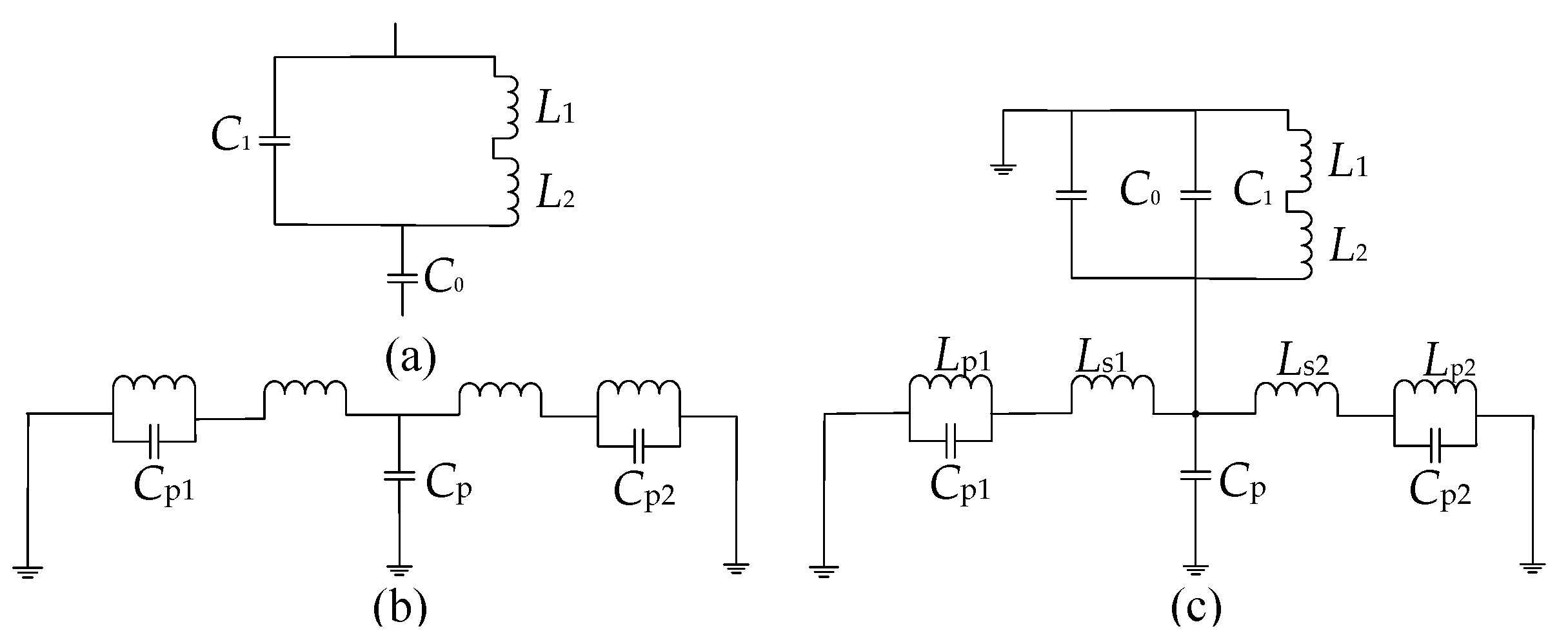
2.2. Analysis of Resonance Performance of Archimedean Spiral EBG Structure

It is necessary to analyze the effect of different parameters d, W, r, dr, start_t, end_t on resonance characteristics of Archimedean spiral EBG structure by using HFSS. The Archimedean spiral EBG structure is modeled by HFSS. The medium of microstrip line is RT/Duorid 5880, the width of microstrip line is Wml = 3 mm, the edge length of EBG structure square is W = 4 mm, the distance between EBG and microstrip line is d = 0.1 mm, and the radius of metal through hole of Archimedean spiral EBG structure is radius = 0.3 mm. start_t = 0 rad, end_t = 9 rad, a = 0.06 mm/°. The sweep frequency analysis of the parameters is carried out by using HFSS, and other parameters are kept unchanged when one parameter is analyzed. The following is an analysis of the simulation results.

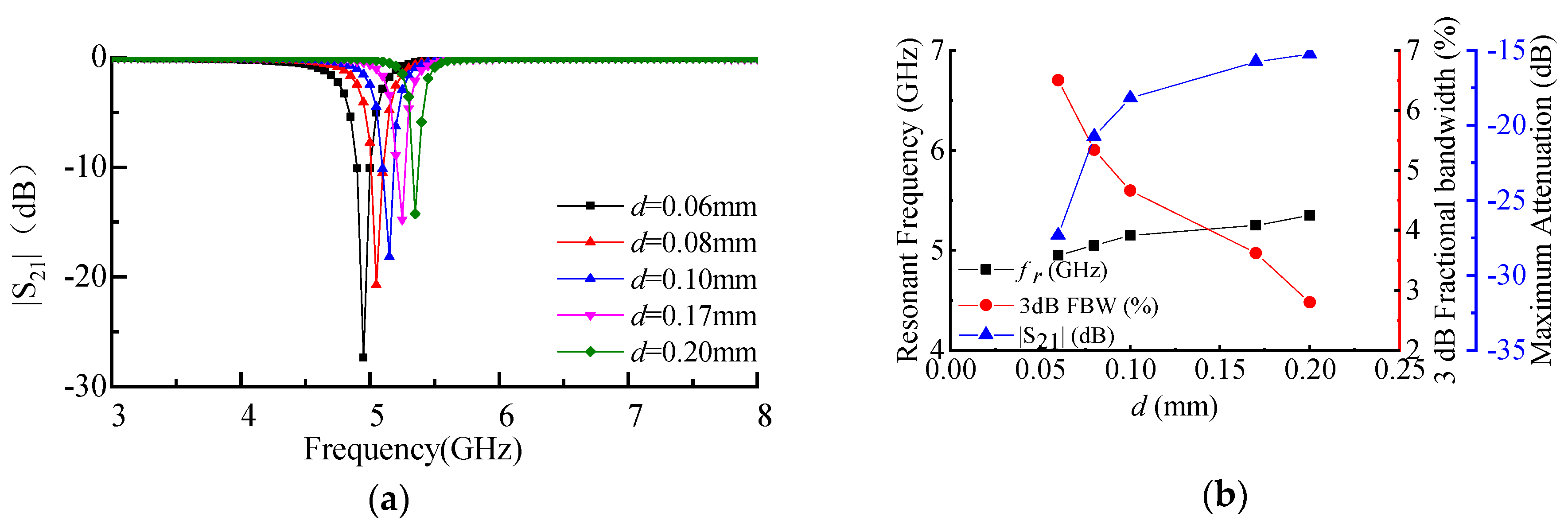
2.2.1. The Spacing d between Archimedean Spiral EBG Structure Unit and Microstrip Line

Simulation results with different d by using HFSS are shown in Figure 3a. Figure 3b shows the curves of resonant frequency, maximum attenuation, and 3 dB fractional bandwidth with varying d. The simulation results show that d increases from 0.06 to 0.2 mm, the resonant frequency of EBG structure increases from 4.95 to 5.35 GHz, the fractional bandwidth of 3 dB decreases from 6.5% to 2.8%, and the maximum stopband attenuation decreases from 27.33 to 15.27 dB. With the increase of d, the 3 dB fractional bandwidth decreases and the maximum attenuation of stopband decreases, and the resonance intensity of EBG resonator decreases. According to Equations (5) and (6), with the increase of d, the capacitance C0 decreases, and the resonance frequency f is inversely proportional to C , so f decreases with the increase of d.

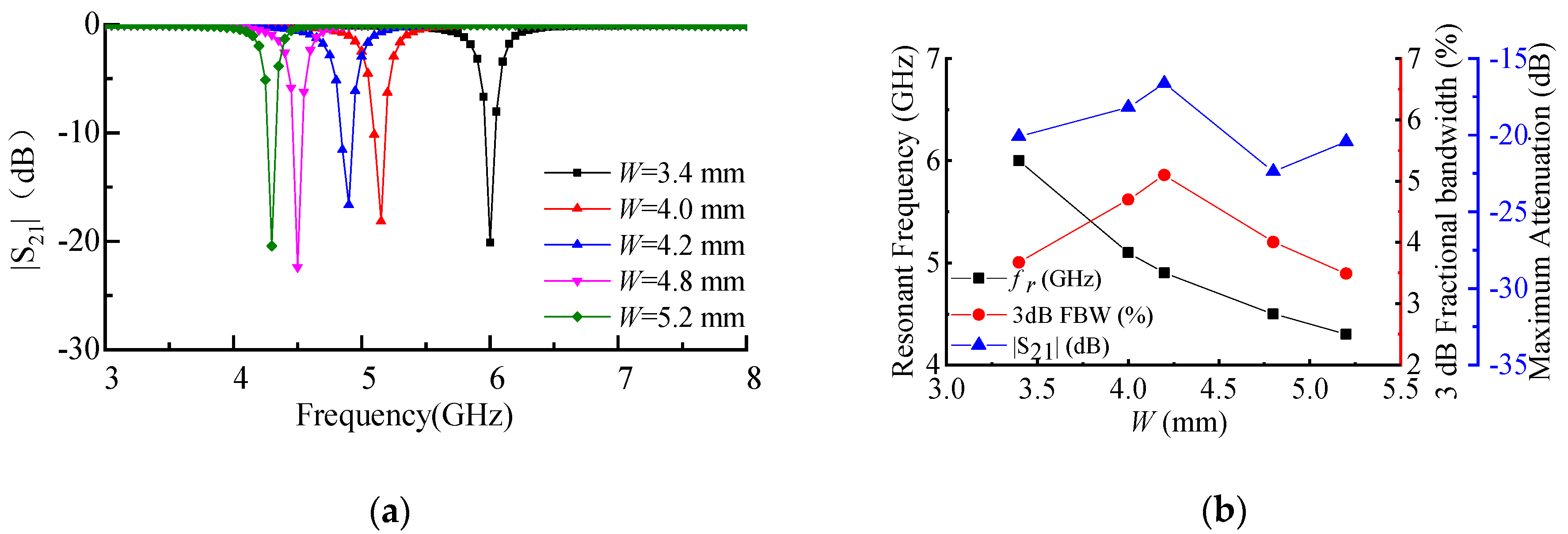
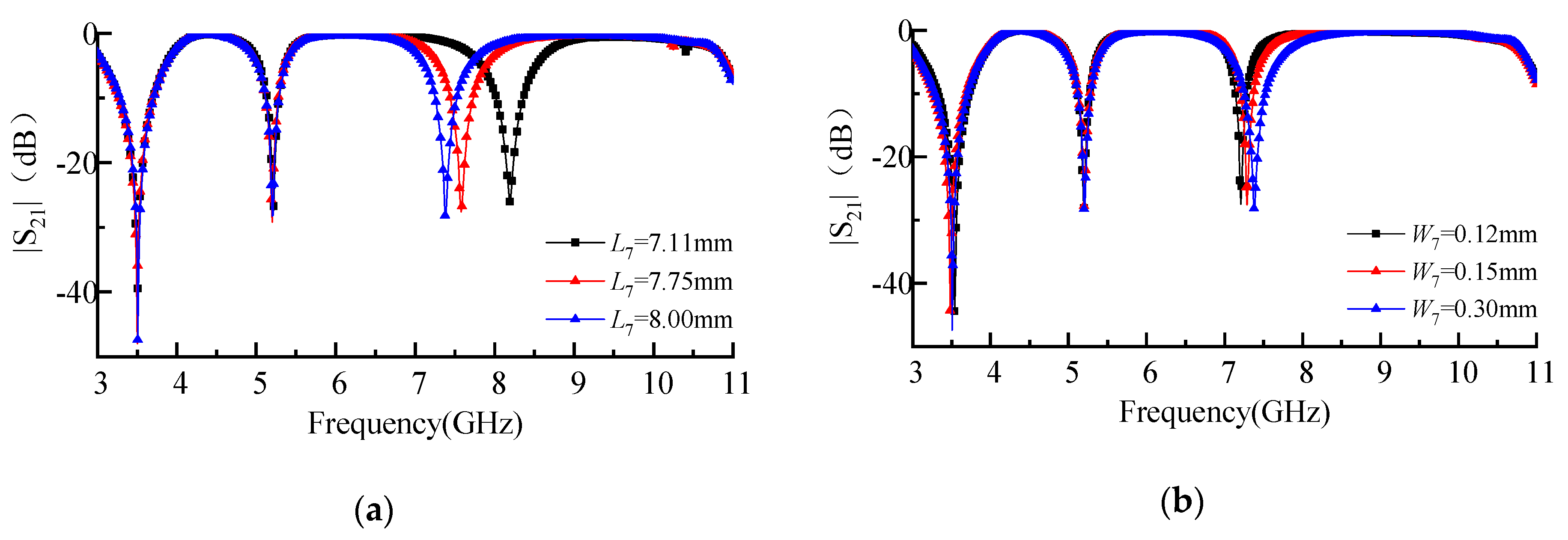
2.2.2. Edge Length W of Archimedean Spiral EBG Structure

Figure 4a shows simulation results with different W by using HFSS. Figure 4b shows the curves of resonant frequency, maximum attenuation, and 3 dB fractional bandwidth varying with time. As shown in Figure 4b, with the increase of W from 3.4 to 5.2 mm, the resonant frequency f decreases from 6 to 4.3 GHz. According to Equation (2), the capacitance C1 and C increase with the increase of W, and while the resonance frequency f is inversely proportional to C . Therefore, the resonant frequency f decreases with the increase of W.

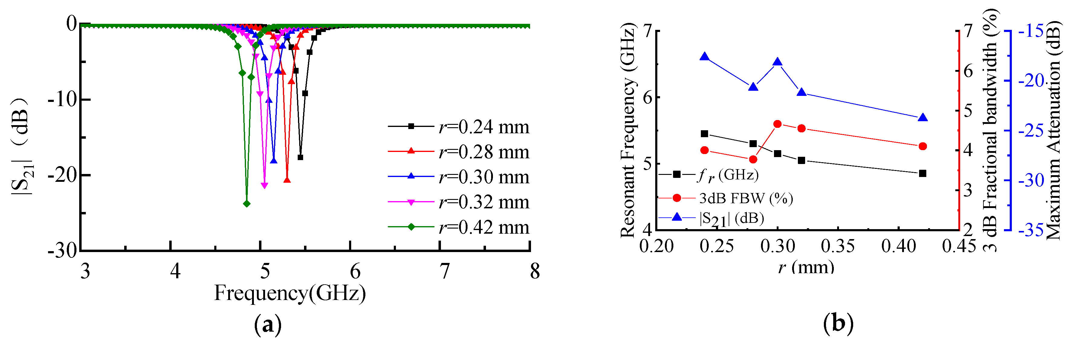
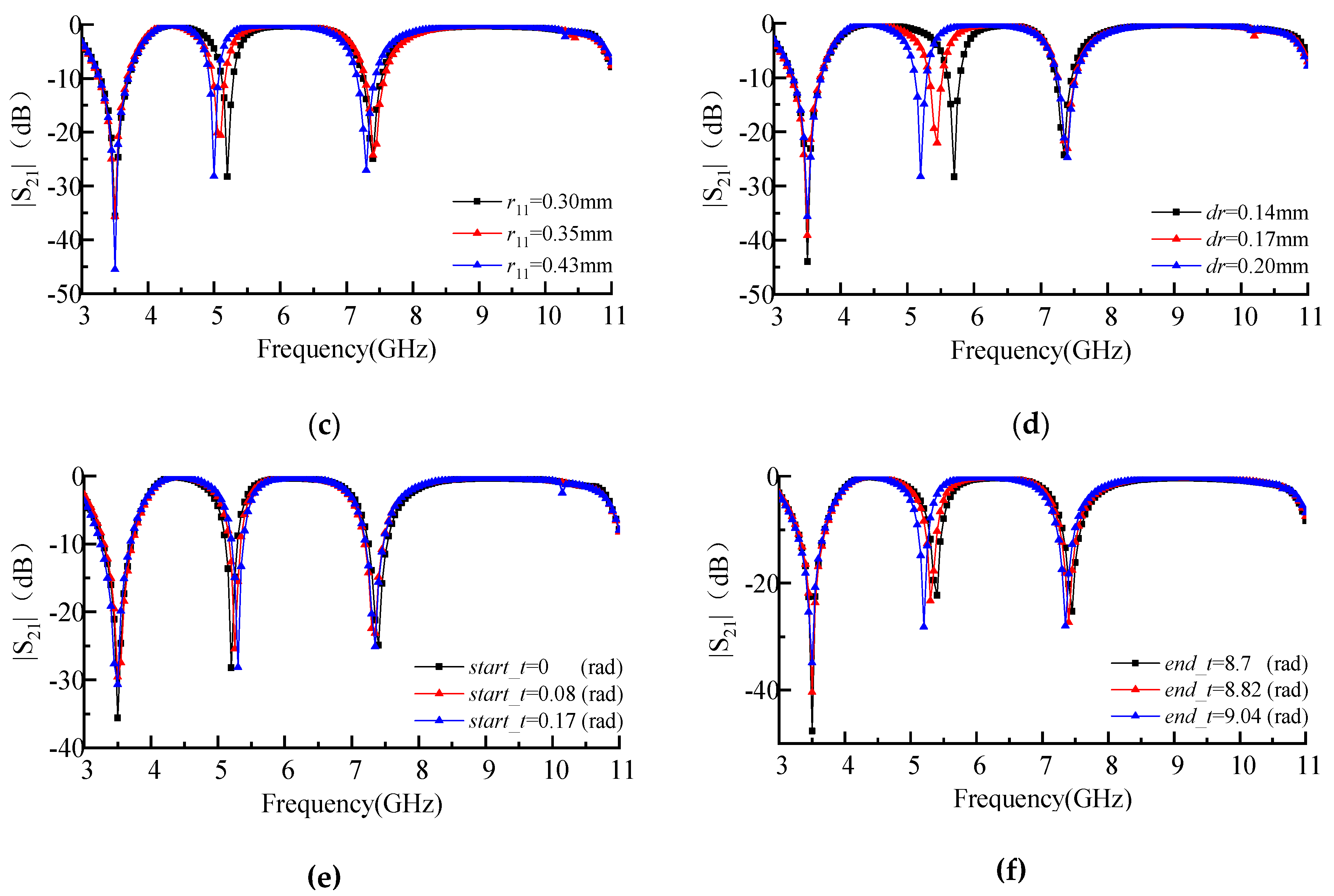
2.2.3. Polar Diameter r of the Archimedean Spiral with at Start_t = 0 rad

Figure 5a shows the simulation results with different r by using HFSS. Figure 5b shows the curves of resonant frequency, maximum attenuation and 3 dB fractional bandwidth varying with different r. The results show that the resonant frequency f decreases from 5.45 to 4.85 GHz, and the maximum stopband attenuation increases from 17.64 to 23.76 dB with the increasing r from 0.24 to 0.42 mm. Equations (8) and (9) show that with the increase of r, inductance L2 and L increases and resonance frequency f decreases for inverse ratio with L .

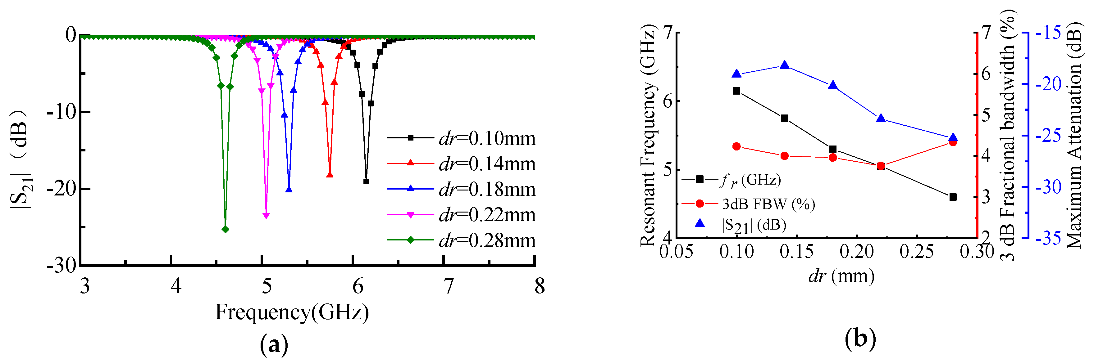
2.2.4. The Difference of Inner and Outer Diameters of Archimedean Spiral dr

Figure 6a shows the simulation results with different dr by using HFSS. Figure 6b shows the curves of resonant frequency, maximum attenuation, and 3 dB fractional bandwidth with varying dr. The simulation results show that the resonant frequency f decreases from 6.15 to 4.6 GHz, 3 dB fractional bandwidth decreases from 4.23% to 3.55% and the maximum stopband attenuation increases from 19.07 to 25.28 dB with the increase of dr from 0.1 to 0.28 mm. Figure 5b shows that with the increase of dr, the resonant frequency decreases, and 3 dB fractional bandwidth tends to narrow, but the change trend is slower.

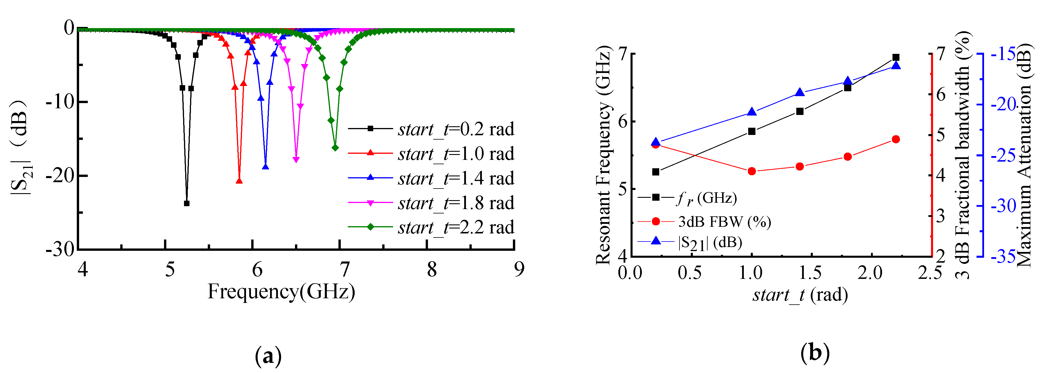
2.2.5. Initial Pole Angle Value of Archimedean Spiral Inductor Start_t

Figure 7a shows the simulation results with different start_t by using HFSS. Figure 7b shows the curves of resonant frequency, maximum attenuation, and 3 dB fractional bandwidth with different start_t. The simulation results show that when start_t increases from 0.2 to 2.2 rad, the resonant frequency f increases from 5.25 to 6.95 GHz, the 3 dB Fractional Bandwidth increases from 4.01% to 4.89%, and the maximum stopband attenuation decreases from 23.76 to 16.22 dB. Equations (8) and (9) show that with the increase of start_t the number of spiral inductor coils decreases, which makes L2 and L decrease. In addition, because the resonance frequency f is inversely proportional to L , it increases with the increase of start_t.

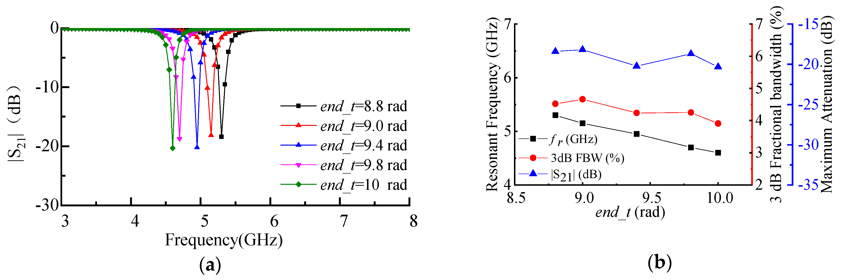
2.2.6. Maximum Pole Angle of Archimedean Spiral Inductor end_t
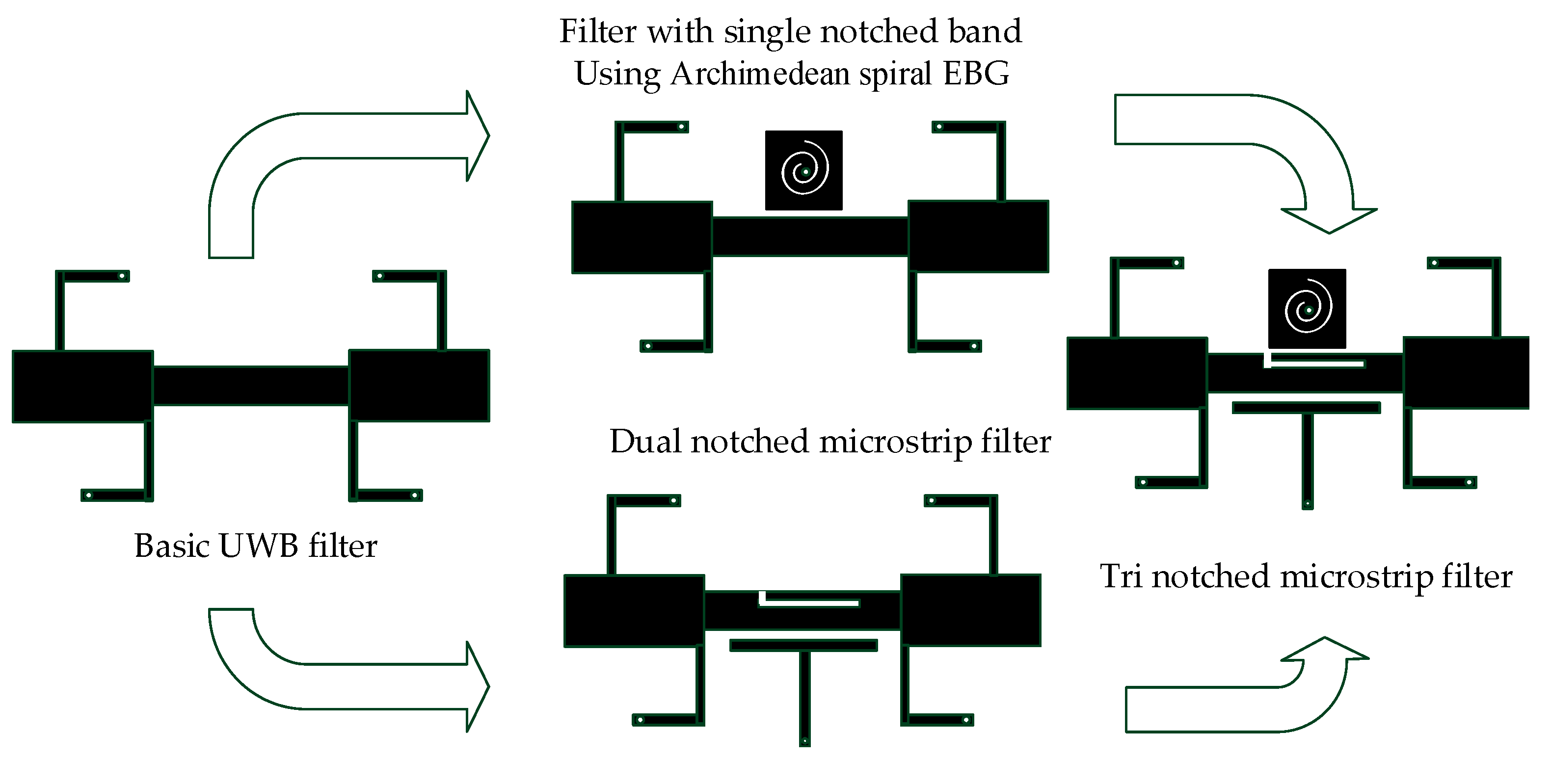
Figure 8a shows the simulation results with different end_t by using HFSS. Figure 7b show the resonant frequency, maximum attenuation, and 3 dB Fractional Bandwidth with different end_t.
The simulation results show that the end_t increases from 8.8 to 10 rad, the resonant frequency of EBG structure decreases from 5.3 to 4.6 GHz, and the fractional bandwidth of 3 dB increases from 4.52% to 3.91%. Equations (8) and (9) show that the increase of end_t leads to the increase of spiral inductor coils, while L2 and L increase with the increase of end_t. As the resonance frequency f is inversely proportional to L , it decreases with the increase of end_t. It can be seen that the resonance characteristics of Archimedean spiral EBG structure vary with the parameters d, W, r, dr, start_t, and end_t. Therefore, the stopband resonance frequency, 3 dB bandwidth, and stopband attenuation of Archimedean spiral EBG structure can be adjusted by adjusting them.

3. Filter Design

Based on the previous work of dual notch bandpass filter [9], the ultra-wideband tri notch bandpass filter is realized by coupling Archimedean spiral EBG structure on the dual notch bandpass filter [9]. The design process of the tri notch bandstop filter is shown in Figure 9. Archimedean spiral EBG structure resonator frequency is designed to operate at 5.2 GHz. The structure of triple notches bandstop microstrip filter using MEBG is shown in Figure 10a. The simulation results of the proposed filter by using HFSS are shown in Figure 10b. The structure of the designed triple notches bandstop microstrip filter is shown in Figure 11a. The simulation results of the proposed filter by using HFSS are shown in Figure 11b. The simulation results show that the 3 dB bandwidth of BPF is 3.01~10.79 GHz and fractional bandwidth is 113.4%. The simulation results of three stopbands of the proposed filter are shown in Table 1.
Figure 12a is the equivalent circuit of Archimedean spiral EBG structure resonant unit. Figure 12b is the equivalent circuit of the dual notch bandpass filter [9]. Figure 12c is the equivalent circuit of the proposed triple notches bandstop microstrip filter. The values of L and C of the equivalent circuit are calculated from Equation (9). The Lumped circuit is simulated and analyzed, and the values of L and C are optimized by using ADS.
The structural parameters of the proposed filter are extracted by ADS as shown in Table 2. Figure 13 shows the comparison of the simulation results by using HFSS and ADS. The simulation results of the resonant frequencies of the three stopbands are identical at 3.5, 5.2, and 7.4 GHz, which further verifies the correctness and the validity of the equivalent circuit of the Archimedean spiral EBG structure and the equivalent circuit of the proposed triple notches bandstop microstrip filter. The function of notch resonator can be realized by coupling Archimedean spiral EBG structure, in which the resonance performance can be adjusted by changing the parameters of Archimedean spiral electromagnetic bandgap structure (ASEBG).

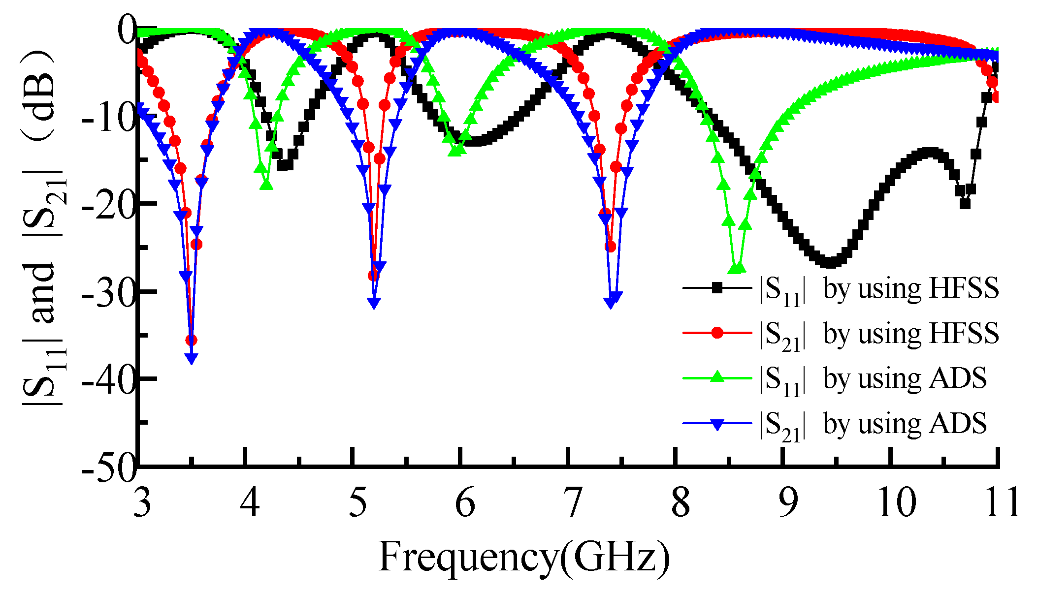
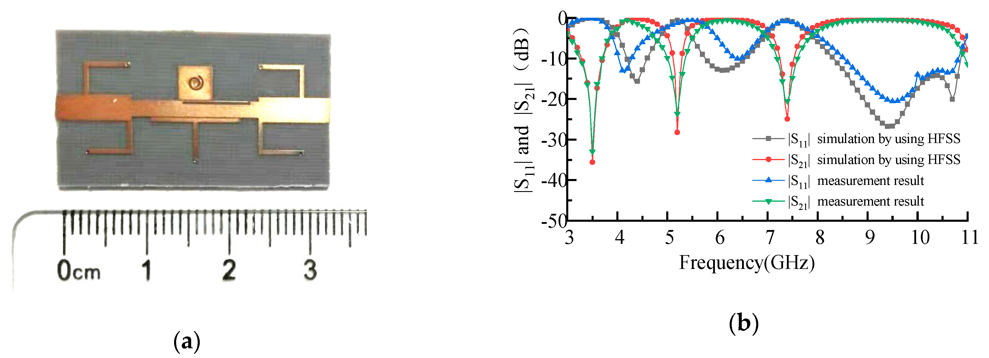
4. Results and Discussion

In this paper, a tri notch stopband ultra-wideband filter is realized by coupling Archimedean spiral EBG structure on the basis of designed ultra-wideband dual-notch microstrip filter [9]. Figure 14a shows a photograph of the proposed filter. Figure 14b shows the results of comparison between simulated data and measured data. As shown in Figure 14b, the filter has three notch resonant center frequencies of 3.5, 5.2, and 7.4 GHz. The 3 dB bandwidths of the proposed filter are 1.2, 0.65, and 0.83 GHz, and the maximum insertion loss of stopband of the filter is 33.6, 24.8, and 21.7 dB by using Vector Network Analyzer to measure the filter performance, respectively.
According to the literature [9], changing L5 can adjust the resonance characteristics of the first stopband produced by T-shaped resonators. Adjusting L7 can change the resonance characteristics of the third stopband produced by L-shaped defective microstrip structure. In order to realize the notch in the 5.2 GHz band, the second stopband is generated by coupling Archimedean spiral EBG structure. The material of the dielectric substrate is RT/Duorid5880 (Rogers Corporation, Chandler, AZ, USA) and the thickness is 1 mm. The final size of the filter is optimized by 0.01 GHz stepped scan frequency using HFSS. The optimized filter structural parameters by scanning frequency analysis of parameters (d, W, r, dr, start_t, end_t) using HFSSare shown in Table 3.

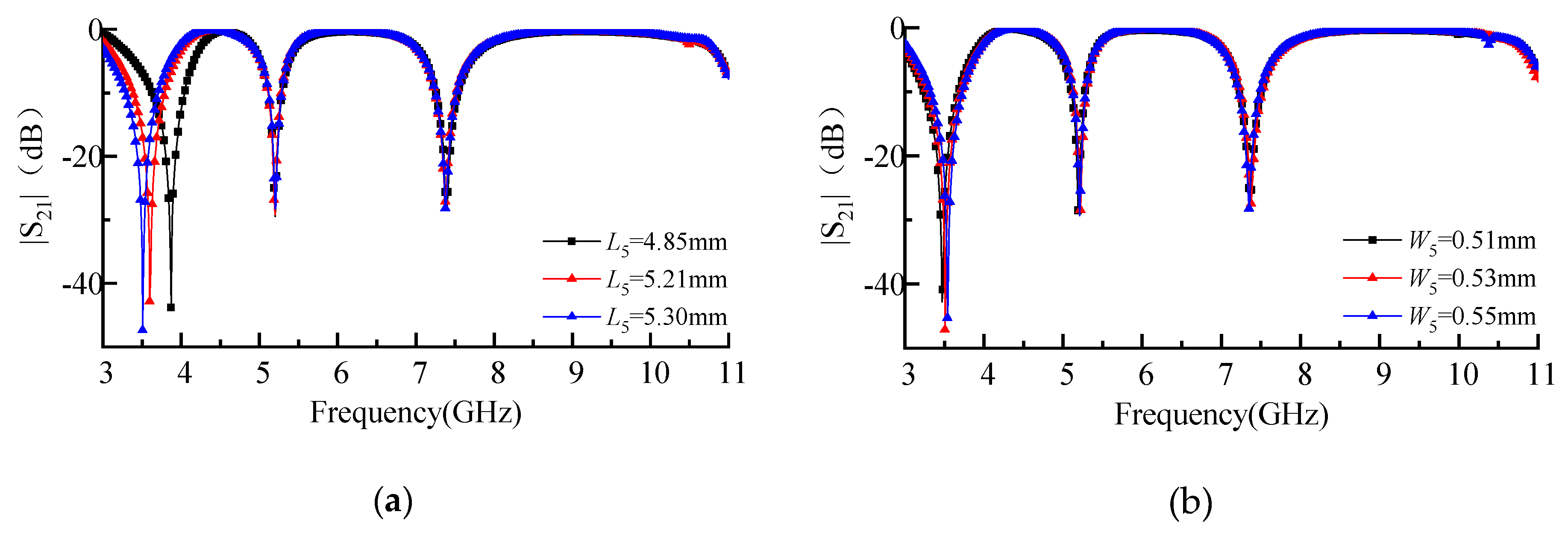
4.1. First Stopband Analysis

The resonant frequency of the first stopband f1 can be adjusted by changing the L5 and W5 of the T-shaped resonator while keeping other parameters unchanged and L6 = 2 L5. As shown in Figure 15a,b, f1 decreases with the increase of L5. However, f1 increases with the increase of W5. In addition, with the increase of L5, the central frequencies of the second stop band f2 = 5.2 GHz and the third stop band f3 = 7.4 GHz, both of which do not change with L5 and W5 of the T-shaped resonator. Therefore, the first stopband resonance frequency of the tri notch stopband filter can be adjusted by adjusting L5 and W5 of the T-shaped resonator.

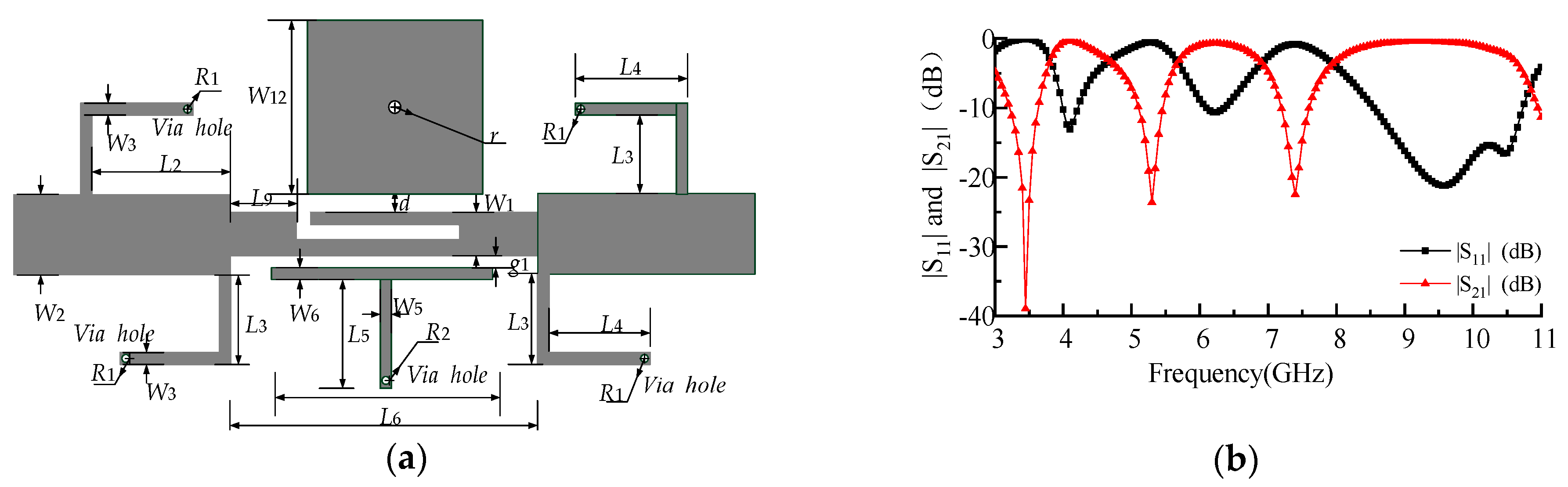
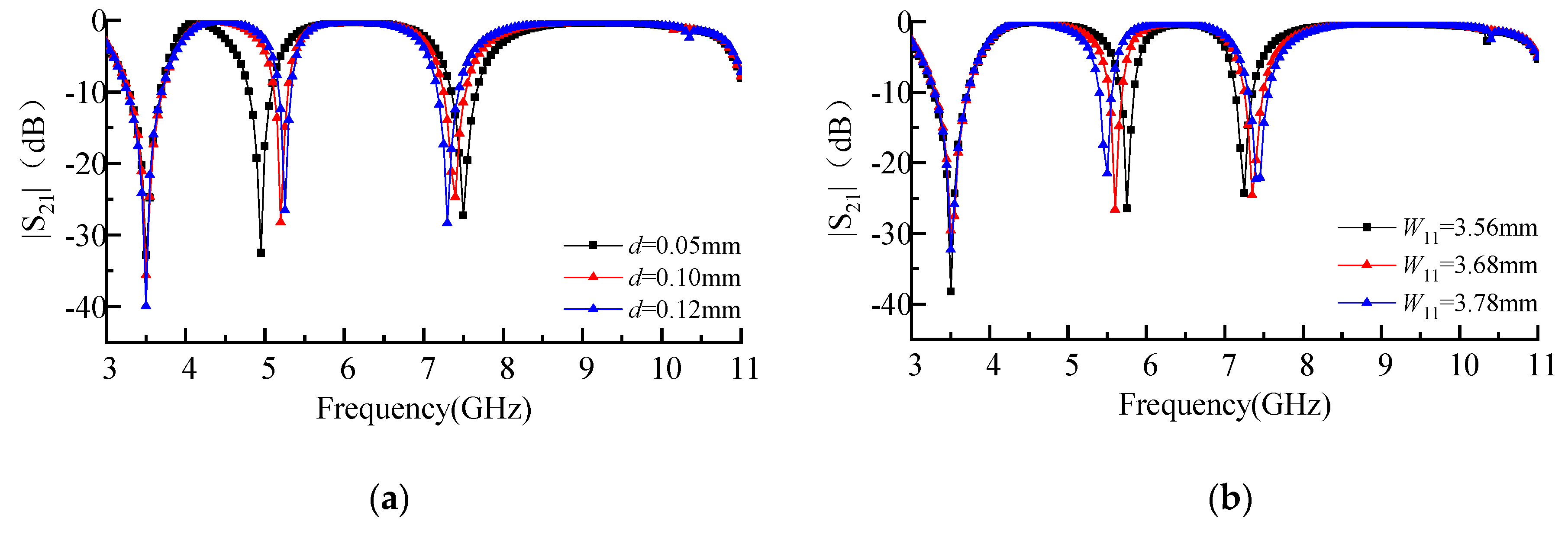
4.2. Second Stopband Analysis

According to the analysis in the previous section, the resonant characteristics of the second stopband can be adjusted by adjusting the parameters W11, r11, dr, d start_t, and end_t of Archimedean spiral EBG structure. The above parameters are analyzed by sweeping frequency while keeping other parameters unchanged in turn.
As shown in Figure 16b–d,f with the increase of W11, r11, dr, and end_t, f2 decreases gradually. As shown in Figure 16a,e, with the increase of d and start_t, f2 increases gradually. As d is the distance between EBG and dual notch filter, the coupling strength between EBG and double notch filter is directly affected. Therefore, when adjusting parameters of EBG, it is necessary to determine the value of d first. As shown in Figure 16a–f, when the parameters W11 r11 d, start_t, and end_t of EBG are changed to adjust f2, f3 will also change. This is because the tri notch filter is realized by coupling the EBG structure to the L-defect structure resonator. The coupling energy between the EBG and the dual notch filter changes with the structural adjustment of the EBG.
However, with the increase of dr, f2 decreases significantly, while f3 remains unchanged, which indicates that dr does not affect the energy coupling between EBG and L-defect resonators. Therefore, the second notch resonance characteristics can be independently controlled by adjusting the size of dr after determining the parameters W11 r11 d, start_t, and end_t. After the above optimization and adjustment, the parameters of the EBG structure are determined, as shown in Table 3.

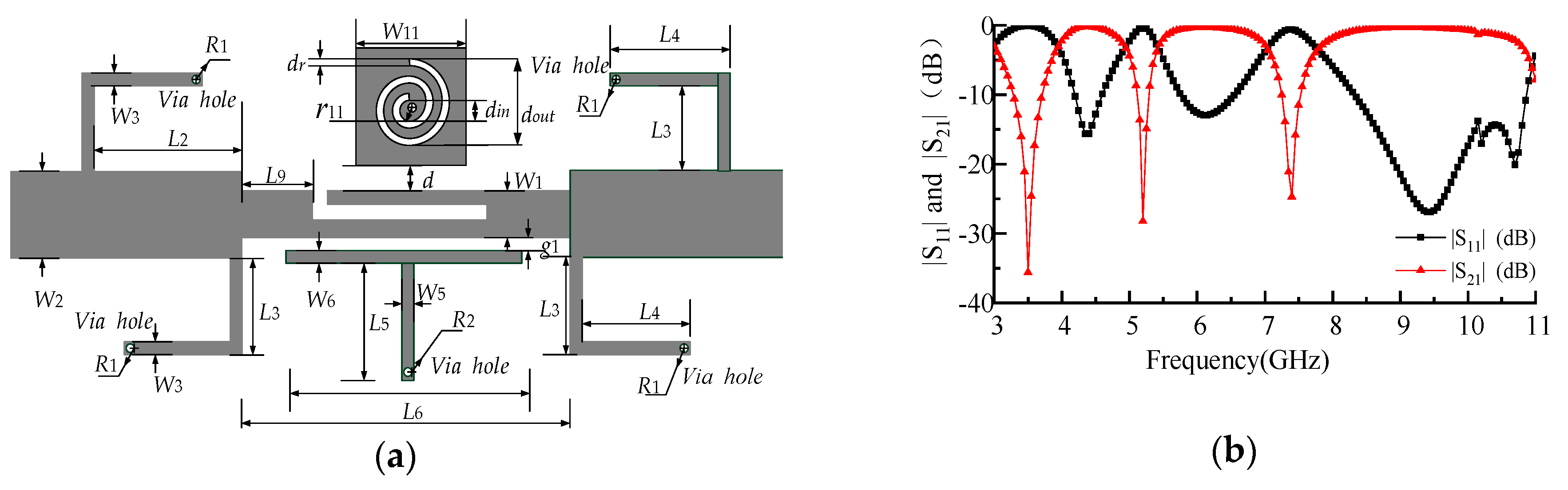
4.3. Third Stopband Analysis

The resonant frequency of the third stopband f3 can be adjusted by adjusting L7 and W7 of the L-shaped defect microstrip structure resonator while keeping other parameters unchanged. As shown in Figure 17a,b, f3 decreases with the increase of L7, but f3 increases with the increase of W7.
In addition, with the increase of L7, the first stopband central frequency f1 = 3.5 GHz and the second stopband central frequency f2 = 5.2 GHz, both of which do not change with L7 and W7 of the L-shaped defect microstrip structure resonator. Therefore, the third stopband resonant frequency can be adjusted by adjusting L7 and W7.
Finally, Table 4 shows the comparison of the proposed filter with other triple notches bandstop microstrip filters [15,17,21,23,24,25,26,27,28,29,35]. Among them, f1, f2, and f3 represent the central resonance frequencies of the first stopband, the second stopband and the third stopband, MSA1, MSA2, and MSA3 represents the maximum stopband attenuation of the first stopband, the second stopband, and the third stopband, FBW3dB_1, FBW3dB_2, and FBW3dB_3 represent 3dB fractional bandwidth of the first stopband, the second stopband, and the third stopband. FBWT represents total fractional bandwidth of the UWB filter. The simulation results show that the three stopband center frequencies of the proposed filter are 3.5, 5.2, and 7.4 GHz, and 3 dB Bandwidth is 1.07, 0.41, and 0.61 GHz, respectively. The 3 dB FBW of the filter is 15.62%, 7.81%, and 8.91% respectively. The maximum stopband attenuation is 35.61, 28.23, 24.90 dB, and the total fractional bandwidth of the UWB filter is 112.8%.

5. Conclusions

In this paper, a novel triple notches bandstop microstrip filter is proposed, which is based on the realized dual stopband filter and Archimedean spiral EBG structure resonator. The three stopband resonant frequencies of the proposed filter are 3.5, 5.2, and 7.4 GHz respectively, and the corresponding maximum stopband attenuation of them are 35.61, 28.23, 24.90 dB, respectively. The consistency of simulation results by using HFSS and ADS verifies the correctness of equivalent circuit model of Archimedean spiral EBG structure and the equivalent resonant circuit model of proposed filter. Therefore, Archimedean spiral EBG structure can be used to realize the notch function of the microstrip filter, and the proposed filter can effectively avoid the interference of wireless communication system in WIMAX band (3.5 GHz), WLAN band (5.2 GHz), and C band of satellite downlink (7.4 GHz).

Author Contributions

X.Z. and T.J. conceived and designed the experiments; X.Z. and T.J. analyzed the data; X.Z. wrote the paper.

Funding

This paper was funded by the International Exchange Program of Harbin Engineering University for Innovation-oriented Talents Cultivation.

Acknowledgments

This work was partially supported by the National Key Research and Development Program of China (2016YFE0111100), Key Research and Development Program of Heilongjiang (GX17A016), the Science and Technology innovative Talents Foundation of Harbin (2016RAXXJ044), the Natural Science Foundation of Beijing (4182077) and China Postdoctoral Science Foundation (2017M620918).

Conflicts of Interest

The authors declare no conflict of interest. The funders had no role in the design of the study; in the collection, analyses, or interpretation of data; in the writing of the manuscript, or in the decision to publish the results.

References

  1. Federal Communications Commission. Revision of Part 15 of the Commission’s Rules Regarding Ultra-Wideband Transmission Systems; First Note and Order Federal Communications Commission, ET-Docket 98-153; Federal Communications Commission: Washington, DC, USA, 2002. [Google Scholar]
  2. Yan, T.; Lu, D.; Tang, X.H.; Xiang, J. High-selectivity UWB bandpass filter with a notched band using stub-loaded multi-mode resonator. AEUE Int. J. Electron. Commun. 2016, 70, 1617–1621. [Google Scholar] [CrossRef]
  3. Gaurav, Y.; Chauhan, R.K. UWB BPF with Single notch band using stub loaded rectangular ring resonator between interdigital structure. In Proceedings of the 2016 IEEE 1st International Conference on Power Electronics, Intelligent Control and Energy Systems (ICPEICES), Delhi, India, 4–6 July 2016. [Google Scholar] [CrossRef]
  4. Wei, F.; Qin, P.-Y.; Guo, Y.J.; Shi, X.-W. Design of multi-band bandpass filters based on stub loaded stepped-impedance resonator with defected microstrip structure. IET Microw. Antennas Propag. 2016, 10, 230–236. [Google Scholar] [CrossRef]
  5. Nouri, S.; Nourinia, J.; Ghobadi, C.; Alizadeh, F.; Mohammadi, B. Erratum for: Design and analysis of compact BPF with dual notch bands based on stepped-impedance resonator for UWB applications. Microw. Opt. Technol. Lett. 2017, 59, 672–674. [Google Scholar] [CrossRef]
  6. Kamma, A.; Das, R.; Bhatt, D.; Mukherjee, J. Multi mode resonators based triple band notch UWB filter. IEEE Microw. Wirel. Compon. Lett. 2017, 27, 120–122. [Google Scholar] [CrossRef]
  7. Borhani, S.J.; Honarvar, M.A.; Virdee, B.S. Quad notched-band UWB BPF based on quintuple-mode resonator. Int. J. Microw. Wirel. Technol. 2017, 9, 1–7. [Google Scholar] [CrossRef]
  8. Lu, X.; Wei, B.; Xu, Z.; Cao, B.; Zhang, X.; Wang, R.; Song, F. Superconducting ultra-wideband (UWB) bandpass filter design based on quintuple/ quadruple/triple-mode resonator. IEEE Trans. Microw. Theory Tech. 2015, 63, 1281–1293. [Google Scholar] [CrossRef]
  9. Zheng, X.M.; Pan, Y.W.; Jiang, T. UWB bandpass filter with dual notched bands using T-shaped resonator and L-shaped defected microstrip structure. Micromachines 2018, 9, 280. [Google Scholar] [CrossRef]
  10. Zheng, X.M.; Liu, W.Q.; Zhang, X.W.; Jiang, T. Design of dual band-notch UWB bandpass filter based on T-shaped resonator. In Proceedings of the 2016 Progress in Electromagnetic Research Symposium (PIERS), Shanghai, China, 8–11 August 2016; pp. 4482–4486. [Google Scholar] [CrossRef]
  11. Zheng, X.M.; Jiang, T. Realization of Dual Notch Bands in UWB Bandpass Filter Using Two T-shaped Resonators. In Proceedings of the 2017 International Applied Computational Electromagnetics Society Symposium, Florence, Italy, 26–30 March 2017. [Google Scholar] [CrossRef]
  12. Zhao, J.; Wang, J.; Zhang, G.; Li, J.-L. Compact microstrip UWB bandpass filter with dual notched bands using E-shaped resonator. IEEE Microw. Wirel. Compon. Lett. 2013, 23, 638–640. [Google Scholar] [CrossRef]
  13. Zheng, X.; Jiang, T. Design of UWB bandpass filter with dual notched bands using E-shaped resonator. In Proceedings of the IEEE/ACES International Conference on Wireless Information Technology and Systems, Honolulu, HI, USA, 13–18 March 2016; pp. 1–2. [Google Scholar] [CrossRef]
  14. Wang, B.; Jing, L.; Huang, W.; Tan, F. Ultra-wideband filter with dual notch bands based on ring resonator. Electromagnetics 2017, 37, 212–223. [Google Scholar] [CrossRef]
  15. Janković, N.; Geschke, R.; Crnojević-Bengin, V. Compact tri-band bandpass and bandstop filters based on hilbert-fork resonators. IEEE Microw. Wirel. Compon. Lett. 2013, 23, 282–284. [Google Scholar] [CrossRef]
  16. Song, K.; Xue, Q. Asymmetric dual-line coupling structure for multiple-notch implementation in UWB bandpass filters. Electron. Lett. 2010, 46, 1388–1390. [Google Scholar] [CrossRef]
  17. Song, K.; Pan, T.; Xue, Q. Asymmetric dual-line coupling strip for multiple notched bands: Theory and implementation. Microelectron. J. 2012, 43, 416–422. [Google Scholar] [CrossRef]
  18. Zhou, L.-H.; Ma, Y.; Shi, J.; Chen, J.; Che, W. Differential dual-band bandpass filter with tunable lower band using embedded DGS unit for common-mode suppression. IEEE Trans. Microw. Theory Tech. 2016, 64, 4183–4191. [Google Scholar] [CrossRef]
  19. Zhang, C.; Zhang, J.; Li, L. Triple band-notched UWB antenna based on SIR-DGS and fork-shaped stubs. Electron. Lett. 2014, 50, 67–69. [Google Scholar] [CrossRef]
  20. Zakaria, Z.; Mutalib, M.A.; Ismail, A.; Isa, M.S.M.; Ismail, M.M.; Latiff, A.A.; Zainuddin, N.A.; Sam, W.Y. Compact structure of band-pass filter integrated with Defected Microstrip Structure (DMS) for wideband applications. In Proceedings of the European Conference on Antennas and Propagation, The Hague, The Netherlands, 6–11 April 2014; Volume 21, pp. 2158–2162. [Google Scholar] [CrossRef]
  21. Wang, J.; Zhao, J.; Li, J.L. Compact UWB bandpass filter with triple notched bands using parallel U-shaped defected microstrip structure. Electron. Lett. 2014, 50, 89–91. [Google Scholar] [CrossRef]
  22. Kurra, L.; Abegaonkar, M.P.; Basu, A.; Koul, S.K. A compact uniplanar EBG structure and its application in band-notched UWB filter. Int. J. Microw. Wirel. Technol. 2013, 5, 491–498. [Google Scholar] [CrossRef]
  23. Wei, F.; Wang, Z.D.; Yang, F.; Shi, X.W. Compact UWB BPF with triple-notched bands based on stub loaded resonator. Electron. Lett. 2013, 49, 124–125. [Google Scholar] [CrossRef]
  24. Doan, M.T.; Che, W.; Pham, C.D. Novel compact tri-band bandpass filter using square ring short stub loaded resonators. Electron. Lett. 2012, 48, 106–107. [Google Scholar] [CrossRef]
  25. Xu, J. Compact microstrip tri-band bandpass filter using new stubs loaded stepped-Impedance resonator. IEEE Microw. Wirel. Compon. Lett. 2016, 26, 249–251. [Google Scholar] [CrossRef]
  26. Ai, J.; Zhang, Y.H.; Xu, K.D.; Shen, M.K.; Joines, W.T. Miniaturized frequency controllable band-stop filter using coupled-line stub-loaded shorted SIR for tri-band application. IEEE Microw. Wirel. Compon. Lett. 2017, 27, 627–629. [Google Scholar] [CrossRef]
  27. Jadhav, J.B.; Deore, P.J. A compact planar ultra-wideband bandpass filter with multiple resonant and defected ground structure. AEU Int. J. Electron. Commun. 2017, 81, 31–36. [Google Scholar] [CrossRef]
  28. Fertas, K.; Ghanem, F.; Challal, M.; Ouahdi, M.; Fertas, F.; Aksas, R. Design and implementation of a novel tri-band bandstop filter based on hexagonal metamaterials split ring resonators. In Proceedings of the 2017 5th International Conference on Electrical Engineering-Boumerdes (ICEE-B), Boumerdes, Algeria, 29–31 October 2017; IEEE: Piscataway, NJ, USA, 2017. [Google Scholar] [CrossRef]
  29. Gholipoor, M.; Amin Honarvar, M.; Virdee, B.S. UWB bandpass filters with triple notched band characteristics implemented using wave cancellation technique. Microw. Opt. Technol. Lett. 2016, 58, 1875–1879. [Google Scholar] [CrossRef]
  30. Boutejdar, A.; Bennani, S.D. Design and fabrication of tri-stopband bandstop filters using cascaded and multi-armed methods. Adv. Electromagn. AEM 2017, 6, 18–24. [Google Scholar] [CrossRef]
  31. Boutejdar, A.; Omar, A. Miniaturized lowpass and bandstop filters using controlled coupling of open-loop-ring defected ground structure. Microw. Opt. Technol. Lett. 2010, 52, 2575–2578. [Google Scholar] [CrossRef]
  32. Boutejdar, A.; Elhani, S.; Bennani, S.D. Design of a novel slotted bandpass-bandstop filters using U-resonator and suspended multilayer-technique for L/X-band and Wlan/WiMax applications. In Proceedings of the 2017 International Conference on Electrical and Information Technologies (ICEIT), Rabat, Morocco, 15–18 November 2017; pp. 1–7. [Google Scholar] [CrossRef]
  33. Boutejdar, A.; Omar, A. A miniature 5.2-GHz bandstop microstrip filter using multilayer-technique and coupled octagonal defected ground structure. Microw. Opt. Technol. Lett. 2009, 51, 2810–2813. [Google Scholar] [CrossRef]
  34. Rambabu, K.; Bornemann, J. Design and application of grounded pin-pad resonators in LTCC components. Microw. Opt. Technol. Lett. 2010, 47, 321–323. [Google Scholar] [CrossRef]
  35. Chu, Q.X.; Wu, X.H.; Chen, F.C. Novel Compact Tri Band Bandpass Filter With Controllable Bandwidths. IEEE Microw. Wirel. Compon. Lett. 2011, 21, 655–657. [Google Scholar] [CrossRef]
Figure 1. (a) The top view of the MEBG structure; (b) the side view of the MEBG structure; (c) the equivalent circuit diagram of the MEBG structure.
Electronics 08 00964 g001
Figure 2. (a) The top view of ASEBG structure; (b) the side view of ASEBG structure; (c) the equivalent circuit diagram of ASEBG structure; (d) the equivalent circuit for calculating resonance frequency of ASEBG structure.
Electronics 08 00964 g002
Figure 3. (a) Simulation results with different d by using HFSS. (b) Resonant frequency, maximum attenuation, and 3 dB Fractional Bandwidth with different d.
Electronics 08 00964 g003
Figure 4. (a) Simulation results with different W by using HFSS. (b) Resonant frequency, maximum attenuation, and 3 dB Fractional Bandwidth with different W.
Electronics 08 00964 g004
Figure 5. (a) Simulation results with different r by using HFSS. (b) Resonant frequency, maximum attenuation, and 3 dB Fractional Bandwidth with different r.
Electronics 08 00964 g005
Figure 6. (a) Simulation results with different dr by using HFSS. (b) Resonant frequency, maximum attenuation, and 3 dB Fractional Bandwidth with different dr.
Electronics 08 00964 g006
Figure 7. (a) Simulation results with different start_t by using HFSS. (b) Resonant frequency, maximum attenuation, and 3 dB Fractional Bandwidth with different start_t.
Electronics 08 00964 g007
Figure 8. (a) Simulation results with different end_t by using HFSS. (b) Resonant frequency, maximum attenuation, and 3 dB Fractional Bandwidth with different end_t.
Electronics 08 00964 g008
Figure 9. The design process of the triple notches bandstop microstrip filter.
Electronics 08 00964 g009
Figure 10. (a) The circuit of the triple notches bandstop microstrip filter using MEBG; (b) the simulation results of the proposed filter by using HFSS.
Electronics 08 00964 g010
Figure 11. (a) The circuit of the triple notches bandstop microstrip filter using Archimedean spiral electromagnetic bandgap structure (ASEBG); (b) the simulation results of the proposed filter by using HFSS.
Electronics 08 00964 g011
Figure 12. (a) The equivalent circuit of Archimedean spiral electromagnetic bandgap structure (ASEBG) structure resonant unit; (b) the equivalent circuit of the dual notch bandpass Ultra Wideband (UWB) filter; (c) the equivalent circuit of the proposed triple notches bandstop microstrip filter.
Electronics 08 00964 g012
Figure 13. The comparison of simulation results by using HFSS and ADS.
Electronics 08 00964 g013
Figure 14. (a) The photograph of the fabricated triple notches bandstop microstrip filter using ASEBG; (b) the simulation results of the filter by using HFSS.
Electronics 08 00964 g014
Figure 15. (a) Simulation results with different L5 (L5 = 4.85 mm, f1 = 3.87 GHz, L5 = 5.21 mm, f1 = 3.6 GHz, L5 = 5.3 mm, f1 = 3.51 GHz); (b) simulation results with different W5 (W5 = 0.51 mm, f1 = 3.47 GHz, W5 = 0.51 mm, f1 = 3.5 GHz, W5 = 0.55 mm, f1 = 3.54 GHz).
Electronics 08 00964 g015
Figure 16. (a) Simulation results with different d (d = 0.05 mm, f2 = 4.9 GHz; d = 0.10 mm, f2 = 5.2 GHz; d = 0.12 mm, f2 = 5.25 GHz); (b) simulation results with different W11 (W11 = 3.56 mm, f2 = 5.75 GHz; W11 = 3.68 mm, f2 = 5.6 GHz; W11 = 3.78 mm, f2 = 5.5 GHz); (c) simulation results with different r11 (r11 = 0.3 mm, f2 = 5.2 GHz; r11 = 0.35 mm, f2 = 5.1 GHz; r11 = 0.43 mm, f2 = 5.0 GHz); (d) simulation results with different dr (dr = 0.14 mm, f2 = 5.7 GHz; dr = 0.17 mm, f2 = 5.45 GHz; dr = 0.2 mm, f2 = 5.2 GHz); (e) simulation results with different start_t (start_t = 0 rad, f2 = 5.2 GHz; start_t = 0.08 rad, f2 = 5.25 GHz; start_t = 0.17 rad, f2 = 5.3 GHz); (f) simulation results with different end_t (end_t = 8.7 rad, f2 = 5.4 GHz; end_t = 8.82 rad, f2 = 5.3 GHz; end_t = 9.04 rad, f2 = 5.2 GHz).
Electronics 08 00964 g016aElectronics 08 00964 g016b
Figure 17. (a) Simulation results with different L7 (L7 = 7.11 mm, f3 = 4 GHz; L7 = 7.75 mm, f3 = 3.6 GHz; L7 = 8 mm, f3 = 3.5 GHz); (b) simulation results with different W7 (W7 = 0.12 mm, f3 = 3.4 GHz; W7 = 0.15 mm, f3 = 3.5 GHz; W7 = 0.30 mm, f3 = 3.7 GHz).
Electronics 08 00964 g017
Table 1. Simulation results of the proposed filter by using HFSS.
Notch Frequency (GHz)3 dB Bandwidth (GHz)3 dB Fractional Bandwidths (FBW) %Rejection Level (dB)
3.51.0715.6235.61
5.20.417.8128.23
7.40.618.9124.90
Table 2. The extracted parameters in Figure 10c by using ADS.
C (pF)C (pF)L (nH)L (nH)
Cp1 = 1.0675C0 = 2.004L1 = 2.48Lp1 = 0.871
Cp = 0.06C1 = 1.200L2 = 5.07 Ls1 = 0.378
Cp2 = 0.9803-Lp2 = 0.4688Ls2 = 2.189
Table 3. Optimized structural parameters of the proposed filter (the units of length are mm, the units of angle are radian).
LengthLengthWidthWidthRadiusGap Length
L1 = 15L5 = 5.3W1 = 1.95W5 = 0.5R1 = 0.15g1 = 0.1
L2 = 5L6 = 10.6W2 = 3W6 = 0.3R2 = 0.15r = 0.3
L3 = 4L7 = 9W3 = 0.3W7 = 0.1W = 4a = 0.06
L3 = 4L8 = 0.1W4 = 1.4W8 = 0.3d = 0.1dr = 0.2
din = 0.6dout = 1W11 = 4W12 = 7.7start_t = 0end_t = 9
Table 4. Comparison of the proposed filter with other triple notches bandstop microstrip filters.
Ref.f1/f2/f3 (GHz)MSA1/MSA2/MSA3 (dB)FBW3dB_1/FBW3dB_2/
FBW3dB_3 (%)
[15]2.4/3.5/5.215/13/204.2/2.9/4.5
[17]5.2/5.85/820.1/25.6/27.714.4/5.2/10.1
[21]5.2/5.8/8.020.1/23.2/24.61.8/2.3/2.1
[23]3.6/5.9/815.9/25.6/27.32.9/3.7/2.3
[24]2.4/3.5/5.2516.5/18/14.55/3.7/4.2
[25]1.4/2.4/3.451/44/3740.1/23.1/50.2
[26]1.56/2.45/3.4640.2/35.1/33.213.6/8.6/8.1
[28]6.1/6.9/7.615/14/132.3/5.2/1.7
[29]5.4/5.8/8.218.3/21.2/21.513.4/6.4/5.1
[35]2.4/3.5/5.2514.3/15/16.86.2/12.2/11.8
This work3.5/5.2/7.435.61/28.23/24.90 15.62/7.81/8.91

