Article

Electro-Mechanical Design and Creep Analysis of Proposed Enclosure for Flexible Gas Insulated Line Regarding Subsurface Metropolitan Applications of High-Voltage Transmission Lines

1
Department of Electrical Engineering, University of Engineering and Technology, Lahore 54890, Pakistan
2
Department of Polymer Engineering, University of Engineering and Technology, Lahore 54890, Pakistan
3
Department of Electrical Engineering, NFC Institute of Engineering and Fertilizer Research, Faisalabad 38090, Pakistan
*
Author to whom correspondence should be addressed.
Electronics 2019, 8(9), 929; https://doi.org/10.3390/electronics8090929
Submission received: 30 July 2019 / Revised: 20 August 2019 / Accepted: 20 August 2019 / Published: 25 August 2019
(This article belongs to the Special Issue Smart Grid and Future Electrical Networks)

Abstract

:
Land shortage in metropolitan vicinities entails subsurface implementation of power transmission lines (PTLs) which demand structural flexibility, as well as substantial load bearing capability. Thus, development of a flexible gas insulated transmission line (FGIL) necessitates its strength degradation analysis, regarding the synergistic effect of aging and mechanical loadings. Moreover, correlation of conductor and enclosure dimensions of FGIL apropos field distribution, requires careful consideration regarding their dimensional specifications. In this research, a comprehensive electro-mechanical design is performed for the proposed flexible-thermoplastic-enclosure of a 132 kV FGIL by considering the synergistic impact of time and temperature-based aging, along with the effect of external and internal loadings, such as dead load, live load and internal gas pressure. Additionally, a recursive design algorithm for the proposed scheme regarding electro-mechanical aspects, along with aging perspectives is developed. Comparative analysis of proposed and conventional schemes regarding electro-mechanical and aging aspects revealed that the proposed enclosure exhibits the required structural strength, as well as flexibility for trenchless subsurface application of FGILs in metropolitan areas.

1. Introduction

Proliferating industrialization and urbanization has increased the load demand, which necessitates upgradation along with new installation of power transmission lines (PTLs), in order to ensure higher system reliability and stability [1,2,3,4]. Additionally, development of the smart grid [4,5], integration of renewable energy [6,7,8] and the requirement of interruption free operation [9,10] necessitates implementation of PTLs with in metropolitan areas [11,12]. Literature describes that existing PTLs are comprised of underground cables (UGCs) [7,13,14,15], overhead lines (OHLs) [2,11,16,17] and gas insulated lines (GILs) [18,19,20,21]. Researchers have described that implementation of UGCs and OHLs in urban vicinities experience hindrances like spatial proximity [9,22,23], right of way [1,2,24], electromagnetic compatibility (EMC) concerns [3,23,25,26], aesthetics [22,24], trench requirements [14,27], corrosion [1,28] and system failure due to prolonged fault clearance time [9]. In addition, the following problems with the metal enclosures of conventional GILs critically constrain their use in urban areas: Long lay lengths and bending radii [18,19,29], excessive rigidity [18,26,30], their needs for acceleration dampers [20,25,31], jointing complexities [18,20,29], trench development [12,29,32] and corrosion protection [19,25,33].
References [34,35,36,37] suggest that flexible gas insulated line (FGIL) is a potential candidate for the curtailment of complexities associated with metropolitan applications of conventional PTLs. Moreover, FGIL provides following advantages in contrast to the conventional rigid GIL: Acceleration dampers are not required; there is no need for corrosion protection; the incorporation of structural flexibility; a substantially reduced bending radius and lay length, as well as lesser required land area at bends. Moreover, studies [38,39,40] mentioned that flexible enclosures and cables, like FGIL, are feasible for horizontal directional drilling (HDD) based subsurface laying technique which eliminates the trench requirement and is advantageous regarding cable and pipe laying in urban localities. FGIL is basically comprised of a flexible-stranded-conductor, flexible-thermoplastic-enclosure, open cell foam of significant structural strength for concentric conductor alignment and a compressed mixture of dielectric gases as the primary insulation medium. In an FGIL, the stranded conductor acts as the high potential electrode and a braided metallic mesh; placed alongside the inner wall of flexible-thermoplastic-enclosure, it acts as the ground electrode. In contrast to the rigid metallic ground of conventional GIL, the braided metallic ground in FGIL, being placed inside the thermoplastic enclosure, is free from environmental impact and supports the structural flexibility of FGIL. Figure 1 shows the schematic of FGIL [41]. Reference [35] studied the synergistic dielectric characteristics of FGIL along with the effect of enclosure’s pitch upon electrostatic field distribution. Authors of reference [41] analyzed the effect of electrode irregularity upon field distribution in FGIL. Reference [42] compared the flexibility of FGIL with conventional GIL regarding HDD based underground cable laying in metropolitan vicinities. Moreover, references [43,44,45,46,47,48,49,50,51,52] suggest that aging behavior of thermoplastics due to time, temperature and mechanical loadings, needs careful consideration in order to avoid their excessive structural deformation, rapid strength degradation and early enclosure puncture.
Considering the concern of enclosure’s strength degradation regarding synergistic impact of aging and mechanical loadings, in this research, a flexible-thermoplastic-enclosure with significantly high structural strength, as well as flexibility, is proposed for FGIL. In addition, a comprehensive electro-mechanical design is performed for the proposed flexible enclosure of 132 kV FGIL regarding the synergistic impact of time and temperature-based aging, along with the effects of external and internal loadings, such as dead load, live load and internal gas pressure. Autodesk Inventor is used to develop and analyze new, as well as aged models of FGIL, as per the performed mechanical design. Concerning the aged model’s development and analysis, the DIN 8074, DIN 8075, DVS 2205-1, TR-4/2018 and ISO 4437 based standard creep estimations of polyethylene (PE) 100 for the time and temperature dependent modulus, as well as stress bearing characteristics, are considered in order to investigate the aging effect for the proposed scheme [52,53,54,55,56,57,58]. COMSOL Multiphysics is used to develop and analyze the electrical model of proposed FGIL as per the performed electrical design. Finally, a recursive design algorithm is developed for the proposed thermoplastic enclosure regrading electro-mechanical aspects. Analytical and simulation analysis revealed that the proposed flexible-thermoplastic-enclosure exhibits the required structural strength, as well as flexibility regarding metropolitan application of FGIL. Flexible enclosure of FGIL will facilitate its subsurface implementation in metropolitan areas through HDD, and will eliminate the requirement of trench development which will also result in substantial cost saving.

2. Flexible Thermoplastic Variants

Concerning underground implementation of FGIL, strength, flexibility and soil immunity are essential requirements for the enclosure material. Reinforced polyethylene (PE) could provide sufficient flexibility and mechanical strength along with an immunity from biological attack, moisture, acids, alkalis, gases and corrosive elements in soil [59,60]. Further being flexible, PE pipes could be implemented in trenchless underground applications through HDD, thus could facilitate the implementation of FGIL in metropolitan areas [60]. Table 1 gives a brief description regarding variants of PE [54,55,58,60].

2.1. Flexibility Analysis of Polyethylene Variants

Crystalline composition of polyethylene resin is represented by its density, which imposes significant impact upon resin properties like tensile strength, impact strength, softening temperature and stiffness as is represented in Table 1 [59,60]. Further, medium and high density polyethylene materials provide significant immunity from soil, moisture, ultraviolent radiation and rapid crack propagation. Thus, keeping in view the required strength, flexibility and environmental immunity characteristics, different FGIL enclosures of PE 80 and PE 100 grades were modeled and analyzed regarding material flexibility and enclosure bendability by using Autodesk Inventor. Enclosure specifications like dimension ratio, diameter, pressure rating and wall thickness of different specimens used in the comparative appraisal were based upon the ISO 4437 standard. Table 2 gives a detailed description apropos different enclosure specimens used in the comparative appraisal [58]. Despite the same pressure ratings, the dimension ratio of enclosure specimens varied due to the reason that PE 100 has higher tensile strength (TS), long term hydrostatic strength (LTHS) and minimum required strength (MRS) in comparison to PE 80, as is represented in Table 1 [54,55,58,59,60].

2.2. Minimum Longitudinal Bending Radius

Minimum longitudinal bending radius (MLBR) provides an indispensable information regarding structural flexibility and bendability characteristics of a specimen without any persistent deformity [53,61]. MLBR regrading different enclosure specimens given in Table 2 was evaluated on the basis of simulation results and Equation (1) [42].
M L B R =   ( L e n g t h   o f   s p e c i m e n 2 + B e n d i n g   o f   s p e c i m e n 2 ) ( 2 × B e n d i n g   o f   s p e c i m e n )

2.3. Structural Pliability and Longitudinal Bending Analysis

In order to analyze the structural pliability of PE variants, Autodesk Inventor based simulations were performed apropos different enclosure specimens as described in Table 2. For the said purpose, PE 80 and PE 100 materials were developed in Autodesk Inventor by using their respective standard resin characteristics like material type, appearance, density, TS, yield strength, Poisson ratio, Young’s modulus, shear modulus, thermal conductivity, specific heat and thermal expansion coefficient [52,53,58,59,60]. The developed PE 80 and PE 100 materials were than used to configure the respective enclosure specimens, having dimensional specifications as described in Table 2. The developed enclosures were than respectively burdened with cantilever loading in order to perform their structural flexibility appraisal. The limiting factor for enclosure bending was considered to be the safety factor (SF), which was set as two for all the cases. Figure 2a,b shows the simulation results of enclosure bending regarding specimens 2 of PE 80 and PE 100, as described in Table 2, while Figure 3a,b shows the respective SFs while performing the bendability analysis. Figure 4 gives a detailed comparison regarding pliability characteristics of PE 80 and PE 100 based enclosure specimens of Table 2 and reveals that the latter has approximately 16 percent lesser flexibility as compared to the prior one. Further, Figure 5 gives a detailed comparison regarding the MLBRs of enclosure specimens, as enlisted in Table 2, and reveals that PE 100 based enclosures have an approximately 15 percent larger bending radius in comparison to PE 80 based enclosures. LMBRs for different enclosure specimens, as enlisted in Table 2, were evaluated by using Equation (1). Critical analysis revealed that PE 100 exhibits petty deviation regarding structural flexibility and bending radius in comparison to PE 80, which is quite acceptable. PE 100, owing to its higher MRS and LTHS, has higher load bearing characteristics and will serve as a better candidate for FGIL enclosure regarding underground applications in comparison to PE 80. Further, due to its higher density, PE 100 provides better immunity against soil and moisture along with higher TS which will facilitate the HDD based trenchless implementation of FGIL in metropolitan areas.

3. Enclosure Design Deliberation

Considering the fact that the enclosure of FGIL will have to withstand high mechanical stresses in the form of internal and external loadings in addition to its structural aging, a detailed mechanical design is essentially required for the proposed flexible enclosure. Further, direct impact of enclosure dimensions upon electrostatic stresses necessitates critical design and analysis regarding electrical aspects as well. Thus, in this research, detailed electro-mechanical design of PE 100 based proposed enclosure scheme for 132 kV FGIL, along with its practicability analysis regarding various electrical and mechanical aspects was performed.

3.1. Mechanical Design Considerations

3.1.1. Pressure Rating and Dimension Ratio

3.1.1.1. Temperature and Environmental Application Factors

Pressure rating of thermoplastics is directly related with the operating temperature and environmental application aspects; i.e., high temperature and adverse environmental conditions will restrict the pressure rating of polyethylene enclosure to a lower value [51,52,59,62]. Thus, determination of the appropriate temperature application factor (TF) and environmental application factor (AF) is essentially required for the proposed scheme. AF incorporates the adjustment in pressure rating of PE enclosure by considering the effect of chemicals; i.e., fluids and gases that interact with polyethylene [59,62]. Regarding the containment of sulphur hexafluoride (SF6), as well as a mixture of SF6 and nitrogen (N2) were put into a PE 100 enclosure, and AF was selected as 1 [59,62,63]. Further, considering that the hydrostatic design basis (HDB) of PE 100 at 73 0F and 140 0F were specified by Plastics Pipe Institute-TR4/20184, TF regarding the nominal operating temperature of the proposed scheme, i.e., 104 0F, is evaluated through Equation (2) [25,54,56,59]. In Equation (2), TF represents temperature application factor, HDBB is the hydrostatic design basis for base temperature, i.e., 73 0F, HDBH represents the hydrostatic design basis for highest operating temperature, i.e., 140 0F, TB represents base operating temperature, TH represents highest operating temperature, and T1 represents operating temperature [59].
T F = 1   H D B B   H D B H H D B B · [ 1 T B 1 T 1 1 T B 1 T H ]

3.1.1.2. Hydrostatic Design Stress

Hydrostatic design stress (HDS) for a thermoplastic enclosure describes the prolonged circumferential stress that the enclosure can withstand and depends upon the design factor (DF) associated with the specific application [59,60,62]. As per CSA Z662, DF for PE 100 based gaseous applications is considered as 0.5 [64]. Thus, the HDS for the proposed PE 100 based flexible enclosure for pliable GIL is evaluated through Equation (3), where HDS represents the hydrostatic design strength in psi, HDB represents the hydrostatic design basis in psi and DF represents the design factor for gaseous applications [60,64].
H D S =   H D B × D F

3.1.1.3. Dimension Ratio

Pressure rating of thermoplastic enclosure is directly related to its dimension ratio (DR) which depends upon the material characteristics like TS, density and its modulus. Considering the required operating pressure of 100 psi along with the TF and AF for the proposed scheme as described in the Temperature and Environmental Application Factors section, the required DR of proposed PE 100 based enclosure is evaluated through Equation (4) [59,62]. In Equation (4), DR represents the dimension ratio, PR represents the pressure rating in psi, HDS represents the hydrostatic design stress in psi, TF represents the temperature application factor and AF represents the environmental application factor.
D R =   2 × H D S × T F × A F P R + 1

3.1.1.4. External Diameter

Outer diameter (OD) of proposed thermoplastic enclosure depends upon its DR described in the Dimension Ratio section, along with its internal diameter. Internal diameter (ID) of proposed enclosure scheme is directly influenced by the electrostatic and dielectric characteristics of electrical insulation media and at present stage is kept the same as for the conventional scheme. However, after completion of mechanical design, ID will be reconsidered regarding the electrical aspects while performing the electrical design and accordingly necessary adjustments will be performed in the mechanical design. OD for the proposed PE 100 based enclosure for FGIL is evaluated through Equation (5), where OD represents the enclosure’s outer diameter in mm, ID represents the enclosure’s inner diameter in mm and DR represents the dimension ratio [53,59].
O D = D R × I D D R     2

3.1.1.5. Maximum Allowable Operating Pressure

Maximum allowable operating pressure (MOP) of a thermoplastic enclosure depends upon its DR along with the resin properties and is essentially required in order to authenticate the nominal operating pressure of enclosure [58,64]. The MOP could be determined as per the International Organization of Standards (ISO) as well as the American Society for Testing and Materials (ASTM) standard methods. Considering the dimensional specifications of PE 100 based enclosure of FGIL described above, MOP as per ASTM method, as described in ASTM D2837, is evaluated by using Equation (6), where MOP represents the maximum operating pressure in psi, HDB represents the hydrostatic design basis in Psi, DF represents the design factor for gaseous applications and DR represents the dimension ratio [64]. Further, MOP as per ISO method, as described in ISO 9080:2012, is evaluated by using Equation (7), where MOP represents the maximum operating pressure in bar, MRS represents the minimum required strength in MPa, C represents the design factor for gaseous applications and DR represents the dimension ratio [64,65,66].
M O P =   2 × H D B × D F D R     1
M O P =   20 × M R S ( D R     1 ) × C

3.1.2. Incorporation of Creep Estimations

Loads associated with thermoplastic enclosures could be categorized in to short term loads and long term loads. Regarding long term loads, aged modeling and creep estimations regarding modulus as well as hoop stress along with their impact upon permissible overpressure are essentially required [53,60]. Thus, DIN 8074, DIN 8075, TR-4/2018 and ISO 4437 based standard creep estimations of PE 100 for time and temperature dependent modulus, as well as stress bearing characteristics, were considered in order to investigate the impact of aging for the proposed scheme [53,54,55,57,58].

Permissible Creep Stress

Considering the fact that creep strength of a thermoplastic enclosure is a function of time and temperature, determination of permissible hoop stress is essentially required for the proposed scheme in order to ensure safe operation of thermoplastic enclosure during its expected life span. The permissible creep stress for the proposed PE 100 based enclosure operating at 104 0F and with an expected life time of 25 years is evaluated through Equation (8) [53,57]. In Equation (8), σper represents the permissible hoop stress in N/mm2, σv represents the equivalent stress from respective creep diagram in N/mm2, A2 represents the reduction factor for transported substance, A4 represents the reduction factor for material strength and SF represents the safety factor. In addition, considering the effect of joint factor regarding axial stresses, the permissible longitudinal stress for the proposed scheme could be evaluated through Equation (9), where σper (l) represents the permissible longitudinal stress in N/mm2 and fs represents the respective joint factor [53,57].
σ p e r   ( l ) =   σ v   A 2 × A 4 × S F
σ p e r =   σ v   × f s A 2 × A 4 × S F

Permissible Creep Modulus

Regarding thermoplastic enclosures, determination of creep modulus is essentially required, as the modulus depends upon the transported fluid characteristics, operating temperature, life span and the applied tension. The permissible creep modulus for the proposed thermoplastic enclosure is evaluated through Equation (10), where EC(per) represents the permissible creep modulus in N/mm2, E(T, t, σ) represents the creep modulus from creep diagram in N/mm2, A2 represents the reduction factor for transported substance and SF represents the safety factor [53,57].
E C ( p e r ) =   E ( T , t , σ ) A 2 × S F

Permissible Operating Pressure Regarding Creep Approximations

Considering the creep constraints, permissible operating pressure for the proposed scheme essentially needs to be evaluated in order to identify that its nominal operating pressure lies well within the safe limits without imposing additional stresses on line enclosure with the passage of time. The permissible operating pressure is evaluated through Equation (11), where Poper represents the permissible operating pressure in bar, σper represents the permissible creep stress in N/mm2, e represents the wall thickness of pipe in mm and de represents the outer diameter of pipe in mm [53].
P o p e r   =   20 × σ p e r × e d e     e

3.1.3. Longitudinal Deformation Apropos of Pressure and Temperature

Longitudinal deformations in thermoplastic pipes normally occur due to the internal stresses associated with the operating temperature and pressure [60]. Thus, evaluation of longitudinal deformations regarding temperature and pressure are essentially required for the proposed scheme. Temperature dependent longitudinal change (ΔLT) for the proposed PE 100 based enclosure is evaluated through Equation (12), where α represents the linear expansion coefficient, L represents the pipe length in mm and ΔT represents the temperature difference in K [53,57]. Further, pressure dependent longitudinal change (ΔLP), is evaluated through Equation (12), where P0 represents the internal pressure in bar, μ represents the Poisson’s ratio, EC represents the creep modulus in N/mm2, de represents the external pipe diameter in mm and di represents the internal pipe diameter in mm [53,57].
Δ L T =   α × L × Δ T
Δ L P =   0.1 × P 0 × ( 1     2 μ ) E C × ( ( d e d i ) 2   1 ) × L

3.1.4. Buckling Resistance Consideration

Thermoplastic enclosures implemented in underground applications undergo external loadings, such as earth load, live load and surcharge load, as well as internal loadings, such as negative pressure load, which may result in enclosure’s inward deflection [60]. An enclosure’s capability to avoid such deflections is categorized as its buckling resistance and must be evaluated for a specific application in order to identify any possible circumferential deformation in the pipe. Buckling resistance of an enclosure could be categorized in to two types; i.e., for constrained pipe and unconstrained pipe [60].

Buckling Resistance of Constrained Pipe

Regarding underground applications, buckling resistance of thermoplastic enclosure is relatively increased due to its surrounding soil cover; however, the enclosure must be placed at a depth of at least one diameter. Considering the fact that the proposed PE 100 enclosure will be placed at a depth several times greater than its outer diameter, its buckling resistance is evaluated through Equation (14), where PCA represents the allowable external pressure for constrained pipe in psi, N represents the safety factor, Rb represents the buoyancy reduction factor, B’ represents the soil elastic support factor, E’ represents the modulus of soil reaction in psi, E represents the apparent modulus of elasticity and DR represents the dimension ratio [60]. The buoyancy reduction factor for Equation (14) is evaluated through Equation (15), where HW represents the groundwater height in ft and H represents the depth of cover in ft [60]. Further, soil elastic support factor (B’) for Equation (14) could be evaluated through Equation (16) [60].
P C A =   5.65 N × ( R b × B × E × ( E 12 × ( D R     1 ) 3 ) ) 1 2
R b = ( 1 0.33 ) × H W H
B =   1 1   +   4   e   0.065   H

Buckling Resistance of Unconstrained Pipe

The buckling resistance for unconstrained pipe could be evaluated through Equation (17), where PUC represents the allowable external pressure for unconstrained pipe in psi, E represents the modulus of elasticity in psi, μ represents the Poisson’s ratio, DR represents the dimension ratio and f0 represents the roundness factor [60].
P U C =   2 × E × f 0 N × (   1   μ 2   ) × ( 1 ( D R   1 ) ) ^ 3

3.1.5. Prospective External Loadings Regarding Subsurface Implementation

External loadings, such as dead load, live load and surcharge load impose heavy stresses upon the subsurface implemented enclosure, and may result in its circumferential deformation. Thus, such loads must be critically considered while performing design for thermoplastic enclosures which are to be implemented in underground applications.

Dead Load

Regarding subsurface enclosure applications, dead load is basically the weight of soil that appears to exist above the enclosure [60]. Such a load imposes a vertical pressure on the enclosure crown and tends to create circumferential deformity in the pipe. Dead load for the proposed PE 100 based enclosure is evaluated by using Equation (18), where PE represents the vertical soil pressure due to earth load in psf, w represents the unit weight of soil in pcf, and H represents the depth of cover in ft [60].
P E = w × H

Live Load

Concerning the underground enclosure implementation, live load is comprised of the stresses imposed by vehicular traffic existing on the earth’s surface above the enclosure. Such loadings depend upon the tire size, tire pressure, vehicle weight, vehicle speed, pavement type above the enclosure and enclosure depth under the pavement. The American Association of State Highway and Transportation Officials (AASHTO) has described the standard loadings for H20 truck regarding the soil depth along with their respective impact factors regarding rigid and flexible pavements [60]. Considering the fact that flexible pavement will result in larger loadings, maximum live load for the proposed scheme regarding flexible pavement is evaluated through Equation (19), where PL represents the vertical stress on pipe crown due to H20 live load in psi, IL represents the load impact factor and L represents the live load for flexible pavements and unpaved roads in psi [60].
P L =   I L × L

Surcharge Load

Surcharge load is basically comprised of pressure exerted on the soil due to foundations and other stationary loads on the earth’s surface. Such pressure reduces significantly with the increased depth below the earth’s surface, as well as increased horizontal gap from the impact area [53,60]. In addition, considering the constraints regarding right of way, structures are prohibited on both sides of transmission line up to a distance of 15 ft. Thus, surcharge loads could not impose significant stresses in the proposed scheme and could be omitted.

3.1.6. Compressive Stress for Subsurface Implemented Enclosure

Buried enclosures encounter compressive stress due to earth pressure and such stresses may become significant in the case when enclosures are depressurized or experiencing vacuum. Thus, compressive stresses should be critically observed during the design of thermoplastic enclosures. Regarding the proposed scheme, compressive stress is evaluated through Equation (20), where S represents the compressive wall stress in psi, PE represents the earth pressure on pipe in psi and DR represents the dimension ratio [60].
S =   P E × ( D R 1 ) 2

3.1.7. Permissible External Pressure Regarding Underground Applications

Considering the required operational safety, permissible external pressure of buried enclosure should be greater than the total external loadings appearing on the pipe. External loading is basically comprised of dead load due soil weight, live load due to vehicular traffic, surcharge load due to structures and enclosure’s internal vacuum load. Thus, in order to have safe and reliable operation of proposed scheme, enclosure’s inherent external load bearing capability should fulfill Equation (21) [60]. In Equation (21), PCA represents the allowable external pressure for constrained pipe in psi, PE represents the vertical soil pressure due to earth load in psi, PL represents the live load in psi, PES represents the surcharge load in psi and PV represents the internal vacuum in psi.
P C A >   P E +   P L +   P V + P E S

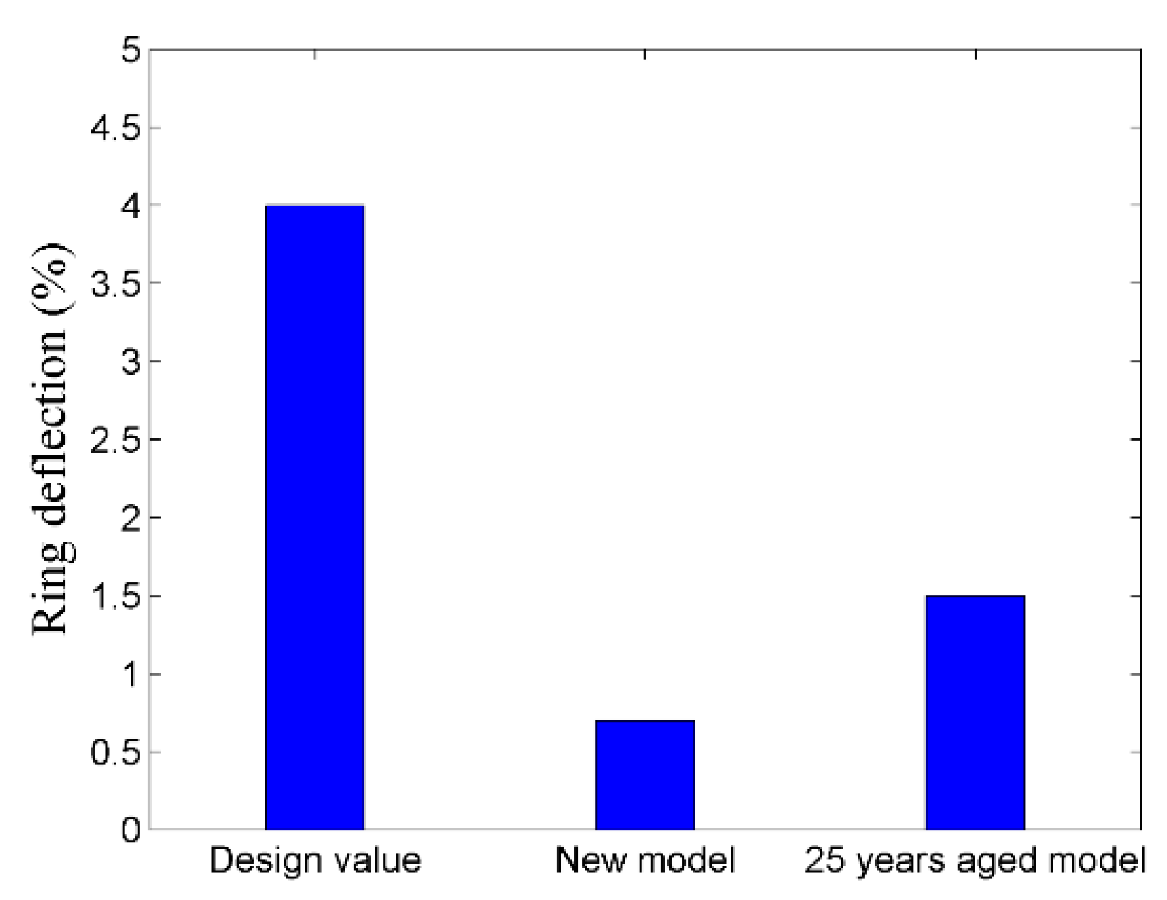
3.1.8. Ring Deflection of for Subsurface Implemented Enclosure

Regarding underground applications, a flexible enclosure undergoes circumferential deflection due to the applied load and tries to shed some load through crown arching. Such arching or deflection is categorized as the percentage ring deflection (PRD) and describes the enclosure’s reaction towards the applied load. PRD is an important factor specifically regrading underground pressure applications of flexible enclosures and should remain within the permissible design window. PRD for the proposed PE 100 based enclosure for FGIL is evaluated through Equation (22), where % ΔY/DM represents the percent deflection in percentage of diameter, ΔY represents the deflection in inches, DM represents the mean diameter in inches, K is the bedding constant, TL is the time lag factor, PE represents the earth load at pipe crown in psi, PL represents the live load at pipe crown in psi, PES represents the surcharge pressure in psi, E represents the modulus of elasticity in psi, DR represents the dimension ratio and E’ represents the modulus of soil reaction in psi [60].
%   Δ Y   D M     =   K   ( T L × P E   +   P L   +   P E S ) 2   E 3   ( D R   1 )   3     +   0.061   E × ( 100 )

3.2. Electrical Design Considerations

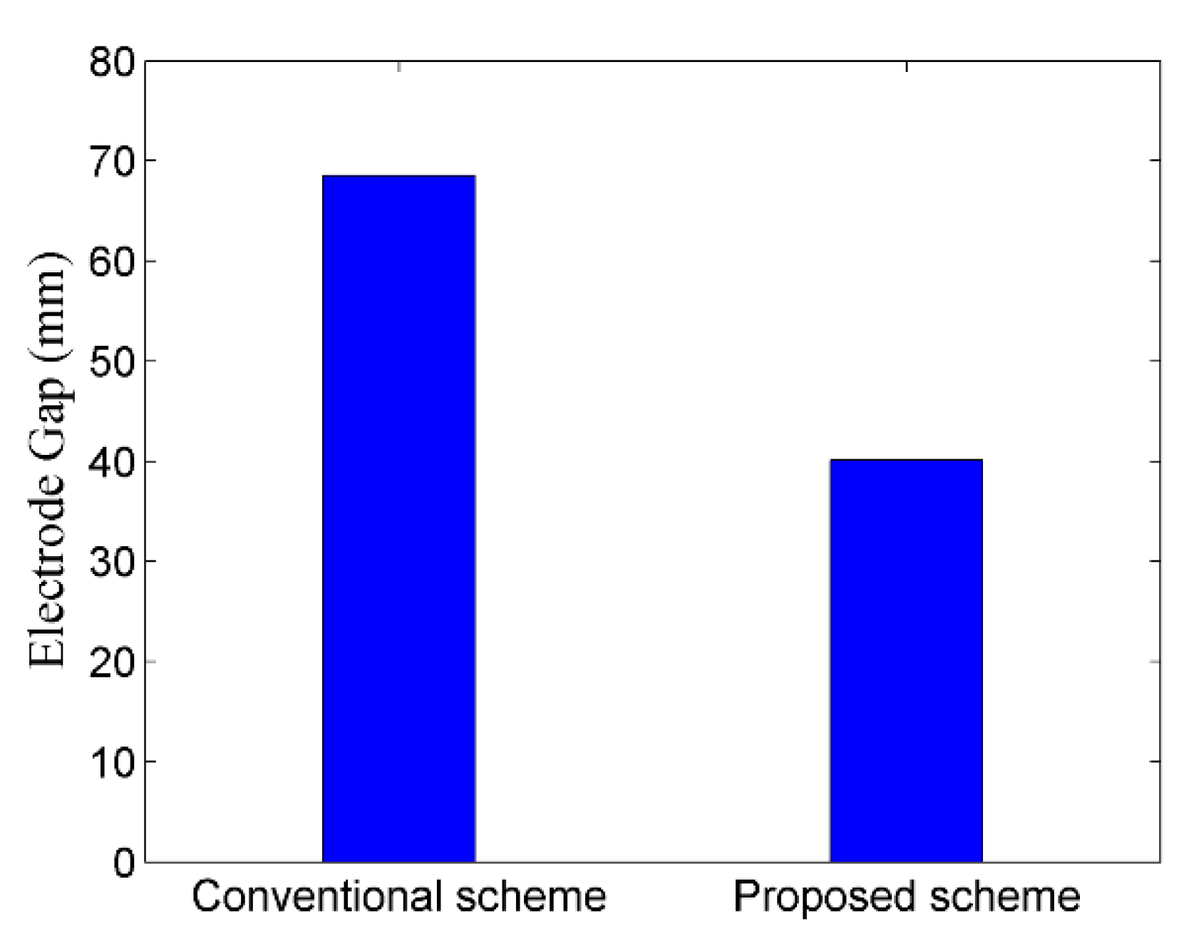
3.2.1. Electrode Gap Optimization

Electrode gap in coaxial FGIL is essential in order to avoid dielectric breakdown and depends upon the dielectric strength of insulating gas, electrode irregularity, field intensity and field utilization factor (FUF). Optimal electrode gap for FGIL is evaluated through Equation (24) which is developed by rearranging the equation for f, where f is FUF, the ratio of mean electric field to the maximum electric field [67,68]. Realizing that Equation (24) is an implicit equation, MATLAB is used to perform its solution through the Newton–Raphson iterative technique. For the said purpose, initial estimate of enclosure’s radius is considered as 50 and iterations are performed for the required accuracy up till four decimals. In Equation (23) and Equation (24), f represents field utilization factor, R represents the metallized enclosure radius in mm and r represents the conductor radius in mm. Dimensional specifications for stranded conductor were based upon the ASTM standard for ACSR conductors and thrasher was selected keeping in view the current requirements for a standard 132 kV GIL [42].
f = r × ( ln R r ) R   r
R =   r e x p ( f × ( ( R r ) 1 ) )

3.2.2. Breakdown Voltage Determination

Breakdown voltage (BV) is the minimum discharge voltage that results in operational interruption of FGIL due to gap discharge in its gaseous dielectric. BV in FGIL depends upon field intensity, electrode gap, FUF, electrode irregularity and gas pressure. Considering the optimized electrode gap in Section 3.2.1, BV for FGIL is evaluated through Equation (25), where P represents gas pressure in kPa, BV represents breakdown voltage in kV and d represents electrode gap in cm [69,70]. Further, considering the impact of electrode’s contour irregularity upon BV, possible degradation in BV is determined through Equation (26), where C represents curvature factor, BV represents breakdown voltage in kV, d represents electrode gap in cm, P represents gas pressure in kPa, S represents electrode roughness factor and F represents FUF [69,70]. Moreover, dielectric medium comprising of a mixture of N2 and SF6 gases in a ratio of 20:80 will also have a lesser BV, due to reduced SF6 content in comparison to the pure SF6 based dielectric medium. Thus, possible degradation in BV due to reduced SF6 content in the dielectric mixture is determined through Equation (27), where m represents the degradation in BV due to reduced SF6 content and n represents the percentage the SF6 in the dielectric mixture [70].
B V = 1.321 × ( P d ) 0.915
B V = 0.8775 × F × S × C × P × d
m = 38.03 × n 0.21

3.2.3. Electrostatic Field Concerns

Concerning the electrostatic constraints for FGIL, critical electric field intensity must be well above the design and operational values of electric field [69]. Thus, design and operational magnitudes of electric field in the proposed PE 100 based FGIL needs careful consideration and are determined through Equation (28) by considering BIL voltage and nominal operating voltage respectively [67,68]. Moreover, Equation (28) is rearranged as Equation (29) in order to determine the critical electric field for proposed scheme by using Equation (23), Equation (26) and Equation (27). In Equation (29), BV represents breakdown voltage, as evaluated using Equations (26) and Equation (27).
E m a x =   U 0 r × ln ( R r )
E c =   B V f × ( R r )

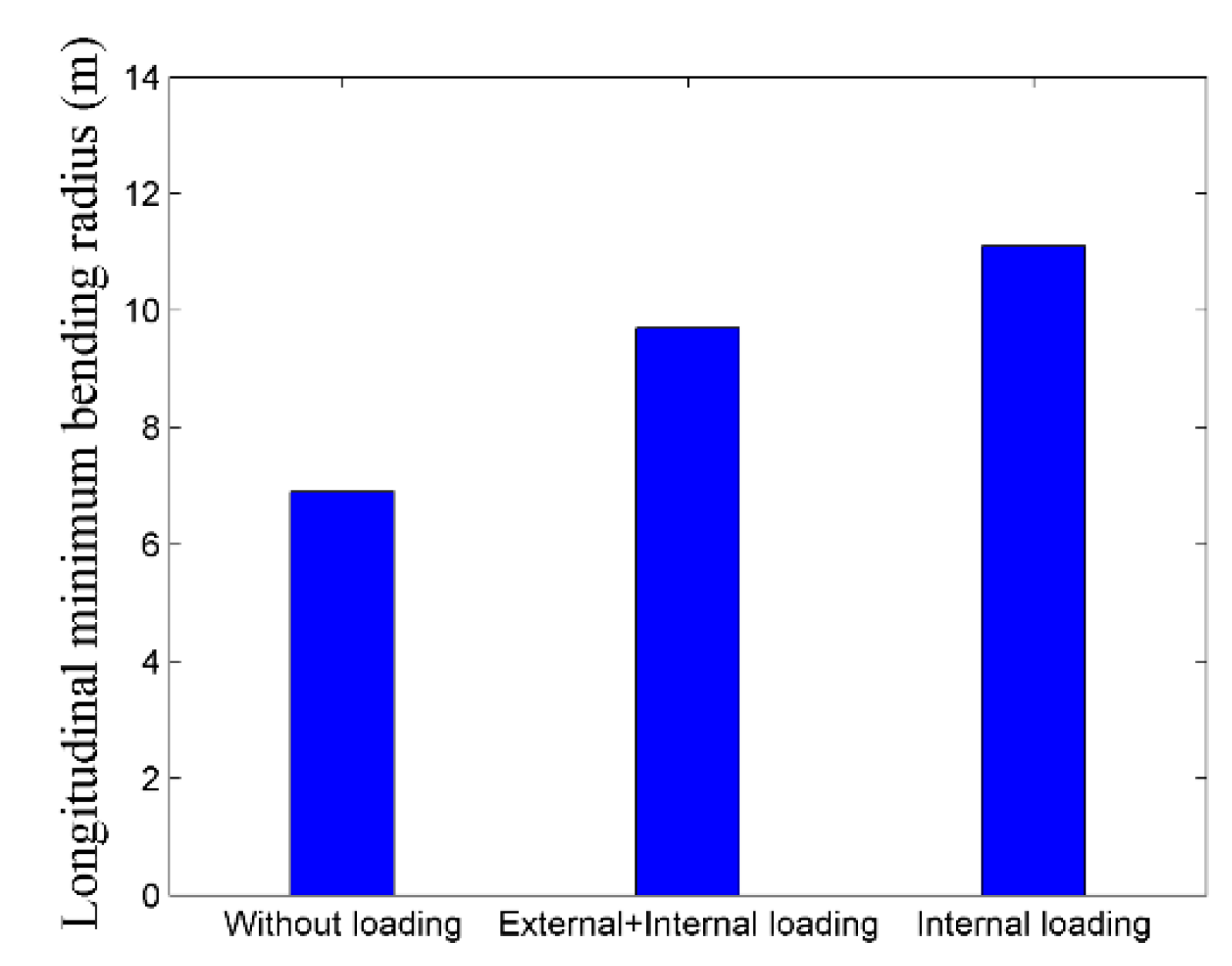
3.3. Determination of MLBR

MLBR is an important parameter regarding inherent flexibility of conductors and cables without resulting in their permanent deformation. Based upon the simulation results, the MLBR for PE 100 enclosure is evaluated through Equation (1) [42]. Further, based upon manufacturer’s data, the MLBR for PE 100 is evaluated through Equation (30), where MLBR is the minimum longitudinal bending radius of enclosure in mm, α is the minimum long-term bend ratio for HDPE pipe and OD is the outer diameter of enclosure in mm [61,71,72].
M L B R =   α × O D

3.4. Lay Length Consideration

Lay length basically provides an estimate regarding the required land area and enclosure length for performing 180° longitudinal bending while starting, and end points are along the same horizontal plane. A flexible enclosure requires lesser lay length and land area for such bending in comparison to a rigid enclosure. Lay length for PE 100 based FGIL could be evaluated through Equation (31), where S is the required lay length in ft and MLBR is the minimum longitudinal bending radius in ft [72].
S =   θ × π 180 ° × M L B R

4. Design Algorithm Flow Chart

Designing a PE 100 enclosure for FGIL is a recursive process and requires reconsideration regarding prior finalized evaluations in case of unsatisfactory results for forthcoming evaluations. Thus, visualizing interdependency of electrical and mechanical aspects, a flow chart, representing comprehensive design algorithm for the proposed FGIL’s enclosure on the basis of design performed in Section 3 is represented in Figure 6.

5. Results and Discussion

In order to investigate the practicability of proposed scheme, Autodesk Inventor was used to develop and analyze new as well as aged models of FGIL as per the performed mechanical design. Concerning aged model’s development and analysis, DIN 8074, DIN 8075, DVS 2205-1, TR-4/2018 and ISO 4437 based standard creep estimations of PE 100 for time and temperature dependent modulus, as well as stress bearing characteristics, were considered in order to investigate the aging effect for the proposed scheme [54,55,56,57,58]. Further, COMSOL Multiphysics was used in order to develop and analyze the electrical model of proposed FGIL as per the performed electrical design.

5.1. Mechanical Aspects

5.1.1. Dimensional Specification Determination

Regarding mechanical analysis, initially, dimensional specifications like DR, OD and enclosure thickness were finalized as per the scheme described in Section 3.1.1.3 and Section 3.1.1.4 Concerning the associated temperature, environmental and pressure constraints, a DR of 11 and an OD of 155.4 mm were finalized, as per Equation (4) and Equation (5) respectively, which resulted in an enclosure thickness of 14.1 mm.

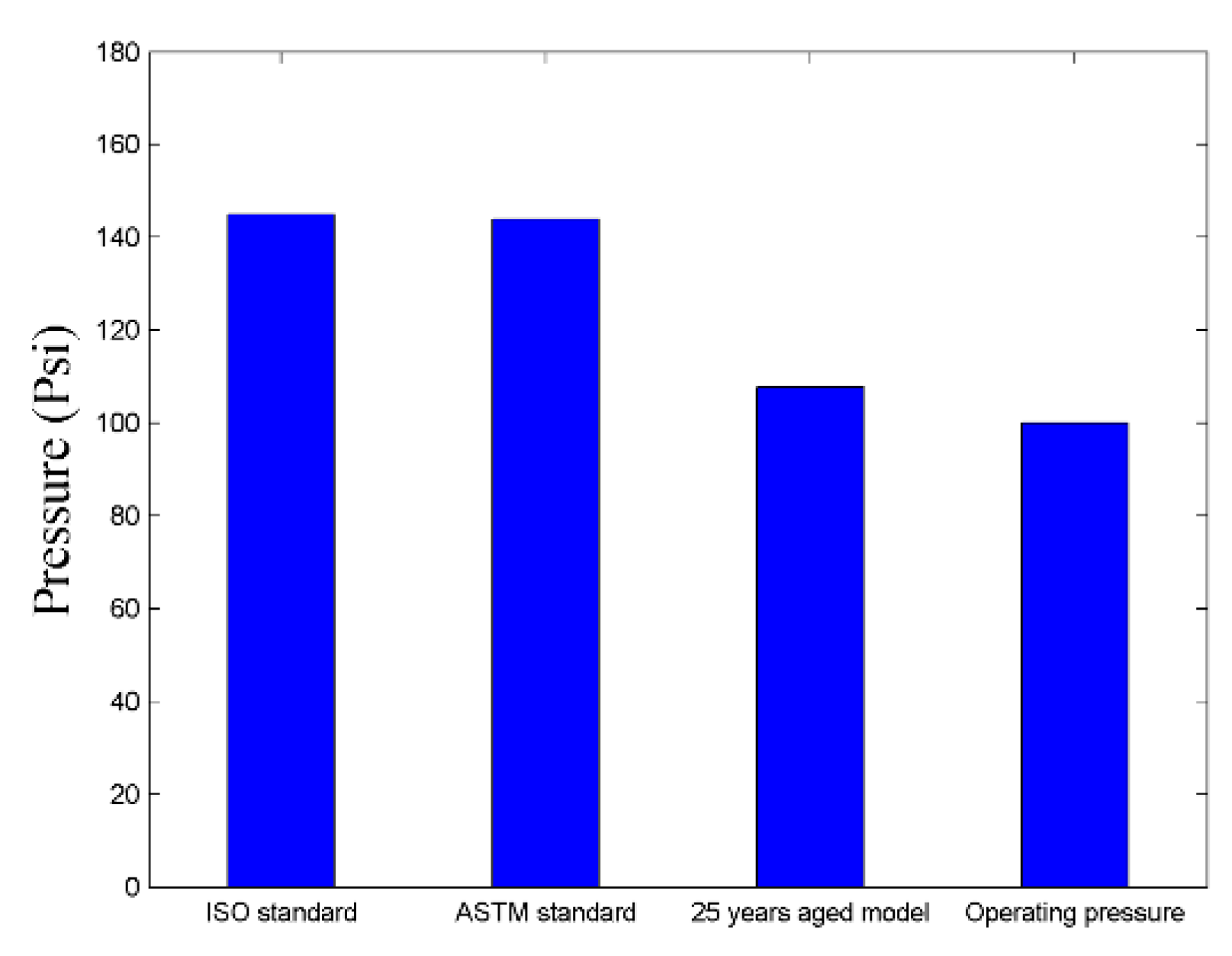
5.1.2. Operating Pressure Comparison

Realizing the operating pressure constraint, MOP for PE 100 enclosure’s current and creep models was determined as per the scheme described in Section 3.1.1 and Section 3.1.2 Aging analysis was based upon a time duration of 25 years. Subsequently, permissible operating pressure for new and aged models was compared with the required operating pressure of FGIL. Critical comparison revealed that new and aged models of PE 100 enclosure with a DR of 11 exhibits 31 percent and 7 percent higher pressure withstanding capability respectively, in comparison to the required operating pressure of FGIL. Figure 7 compares the permissible operating pressure of new and aged models of PE 100 enclosure with the required operating pressure of FGIL.

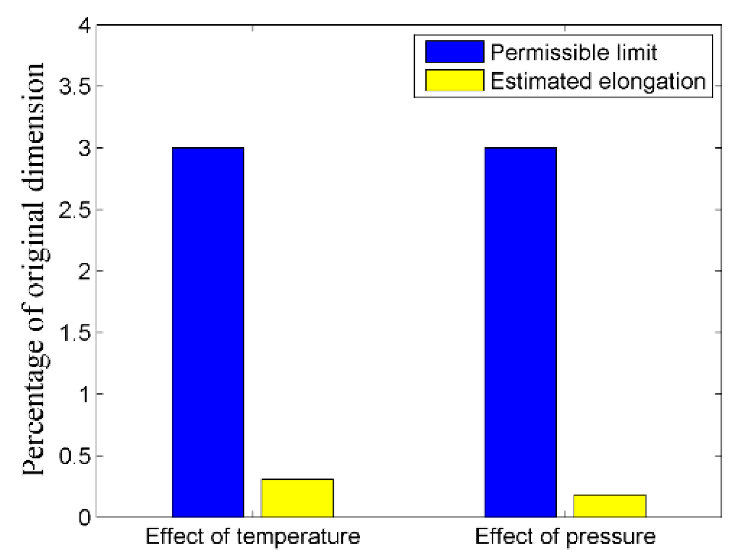
5.1.3. Permissible Longitudinal Variations

Longitudinal deformations due to temperature and pressure were evaluated for PE 100 enclosure as per the scheme described in Section 3.1.3 Subsequently, the enclosure’s longitudinal deformations due to temperature and pressure were compared with their respective allowable limits. Detailed comparison revealed that PE 100 enclosure with a DR of 11 exhibits 9.7 times and 16.7 times lesser longitudinal deformations regarding temperature and pressure in comparison to their respective permissible deformation limits. Figure 8 compares the estimated longitudinal deformations for the proposed scheme regarding temperature and pressure with their respective allowable limits.

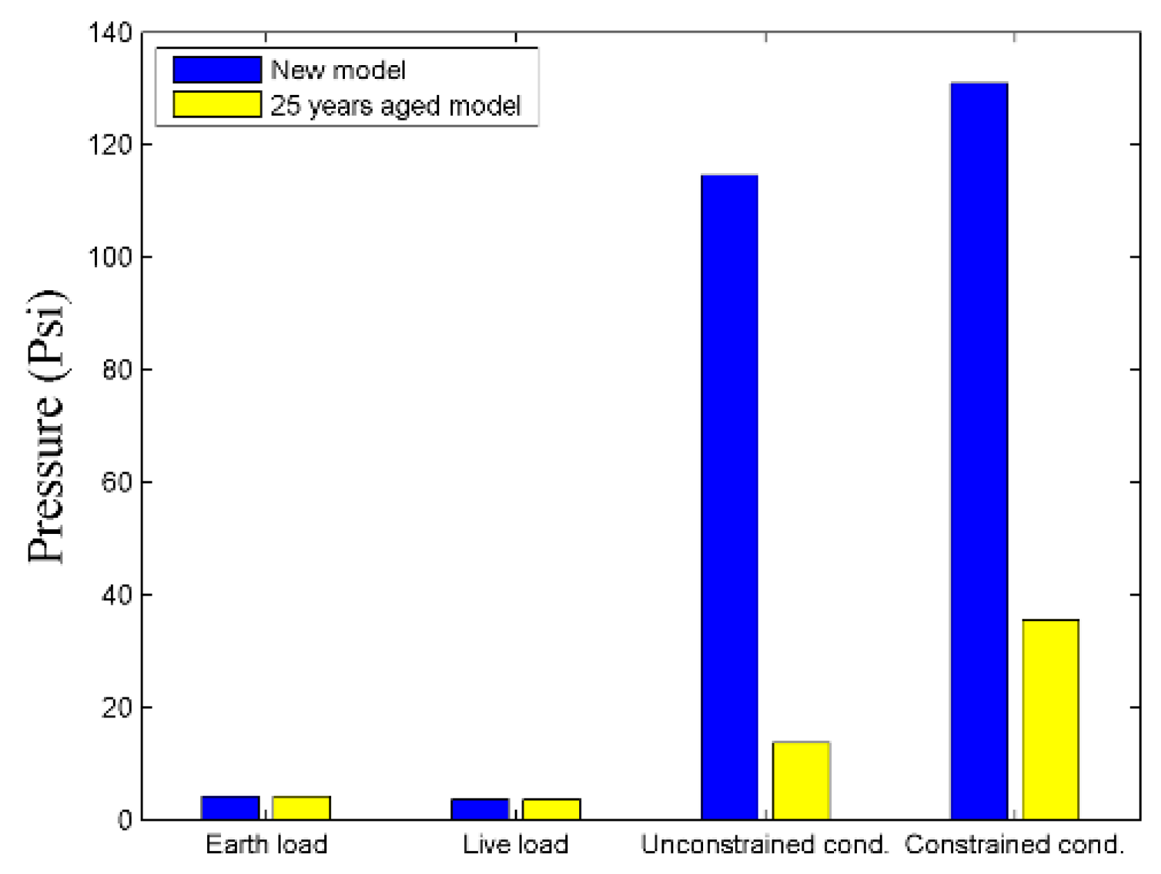
5.1.4. Wall Buckling Appraisal

Concerning the buckling constraint for subsurface application of thermoplastic enclosure, the required wall buckling resistance along with the associated external loadings were computed as per the scheme described in Section 3.1.4 and Section 3.1.5 for PE 100 enclosure having dimensional specifications as determined in Section 5.1.1. The implementation depth for PE 100 enclosure was set as two meters and accordingly different external loadings were considered. Wall buckling analysis was performed for new as well as aged models and aging analysis was based upon a time duration of 25 years. However, the effect of external loadings was kept the same for new and aged models. Detailed wall buckling analysis regarding a constrained enclosure revealed that new and aged models exhibit 16.3 times and 4.5 times higher wall buckling resistance (WBR) in comparison to the applied external load. Moreover, wall buckling analysis regarding an unconstrained enclosure revealed that new and aged models exhibit 14.3 times and 1.8 times higher WBR in comparison to the applied external load. Figure 9 compares the WBR for new and aged models of PE 100 enclosure with the associated external loadings regarding their underground implementation. Figure 9 clarifies that both new and aged models of the proposed scheme fulfilled the essential loading condition for constrained enclosures, as described in Section 3.1.7, and have several times higher permissible external pressure in comparison to the imposed external loadings.

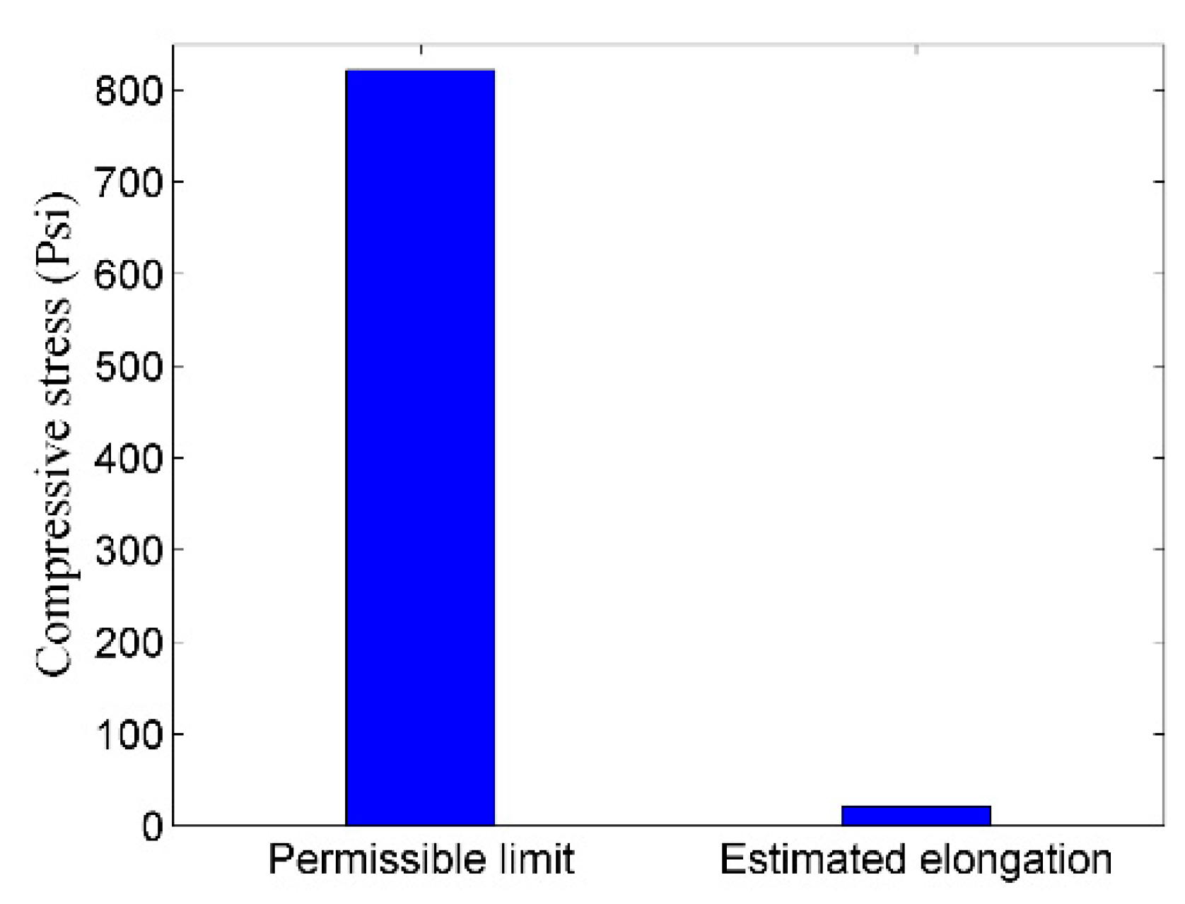
5.1.5. Wall Compressive Stress Assessment

Realizing the importance of compressive stress for subsurface applications, wall compressive stress for the proposed scheme was determined through Equation (20) and was compared with the allowable compressive stress for PE 100 enclosure. For the said purpose, implementation depth for PE 100 enclosure was set as two meters and accordingly external loading was considered. Comparison revealed that the allowable compressive stress for PE 100 enclosure was approximately 39 times higher than the compressive stress encountered by the subsurface implemented FGIL. Figure 10 compares the permissible wall compressive stress with actual wall compressive stress for PE 100 enclosure regarding the proposed scheme.

5.1.6. Percentage Ring Deflection Appraisal

Concerning the PRD, new and a 25 years aged model of PE 100 enclosure were analyzed regarding the effect of external loadings. For the said purpose, dimensional specifications for the PE 100 enclosure were determined on the basis of Section 5.1.1, and implementation depth for the proposed scheme was set as two meters. Considering the permissible design value of 4 percent for thermoplastic enclosures regarding pressure application, PRD for new and aged models along with their associated loadings was determined as per the scheme described in Section 3.1.8 and Section 3.1.5. Detailed comparison revealed that PRD for new and aged models was respectively six times and at 2.8 times lesser than the permissible limit. Figure 11 compares the PRD for the proposed scheme regarding new and aged models with the permissible limit.

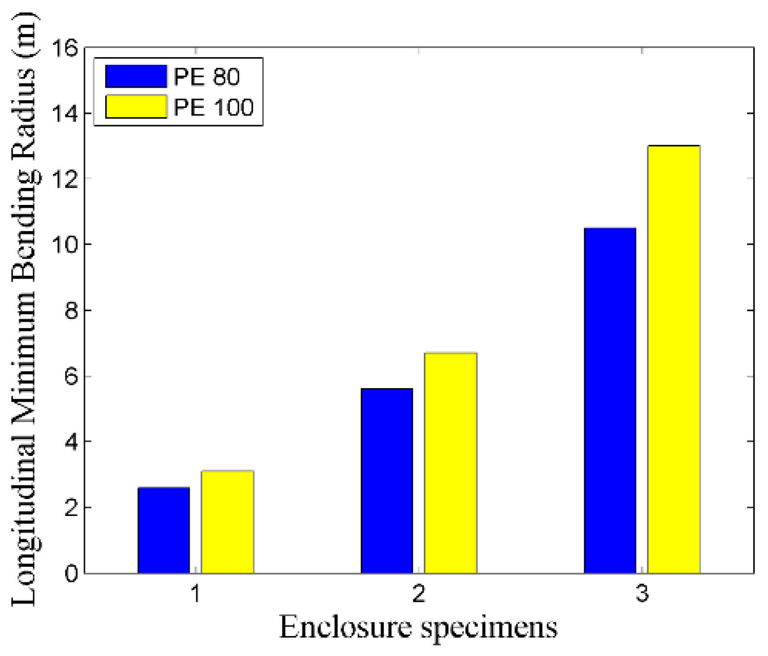
5.1.7. MLBR Comparison

Regarding MLBR, loaded and unloaded models of PE 100 enclosure were analyzed in comparison to the rigid enclosure of conventional GIL. The loaded PE 100 model was comprised of external loadings mentioned in Section 3.1.4, along with internal loadings due to pressurized gas. Dimensional specifications for loaded and unloaded models were determined on the basis of Section 5.1.1, and the minimum safety factor during enclosure bending was considered as two. Comparison revealed that MLBR for unloaded model of the proposed scheme was 40 times lesser in contrast to the conventional scheme. Further, regarding the consideration of both external and internal loadings, MLBR for the proposed scheme was 24 times lesser compared to the conventional scheme. Moreover, regarding the case of internal loadings only, MLBR for the proposed scheme was 21 times lesser in comparison to the conventional scheme. Figure 12 shows the MLBR of the proposed scheme regarding different cases discussed above.

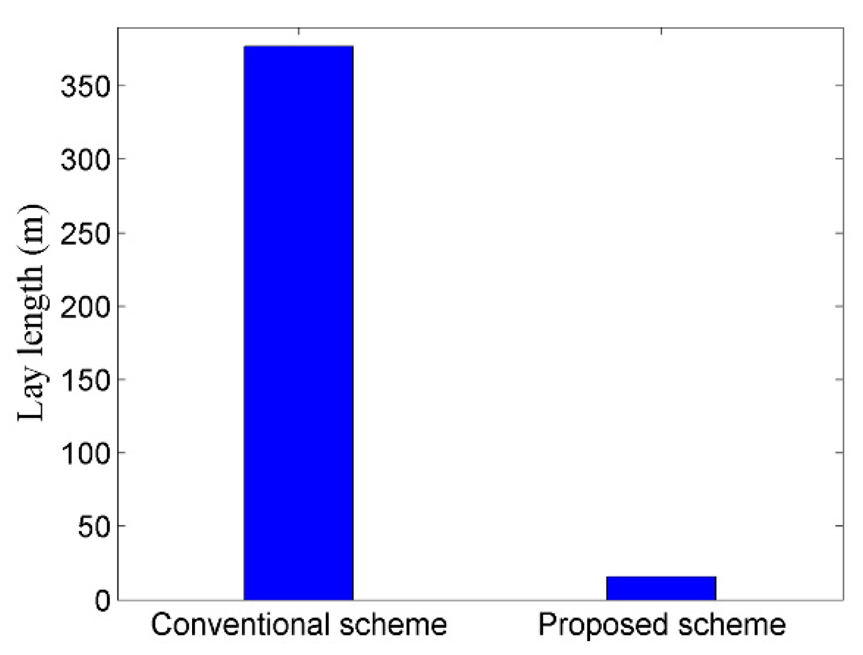
5.1.8. Lay Length Comparison

In order to analyze the advantage of lesser MLBR, required lay length of the proposed and conventional GIL regarding similar horizontal plane were compared as per the scheme described in Section 3.4. For said purpose, MLBR of loaded FGIL as evaluated in Section 5.1.7, and MLBR of standard 132 kV a conventional GIL were considered. Figure 13 shows the required lay length for conventional and proposed GIL schemes. Comparison revealed that the required lay length for proposed PE 100 enclosure based FGIL was approximately 23 times lesser in comparison to the required lay length for conventional GIL.

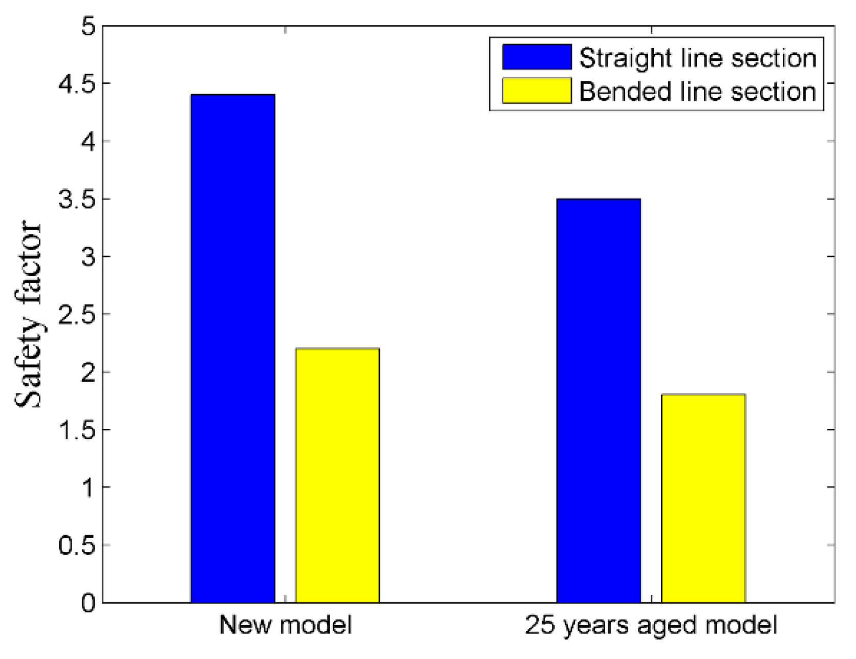
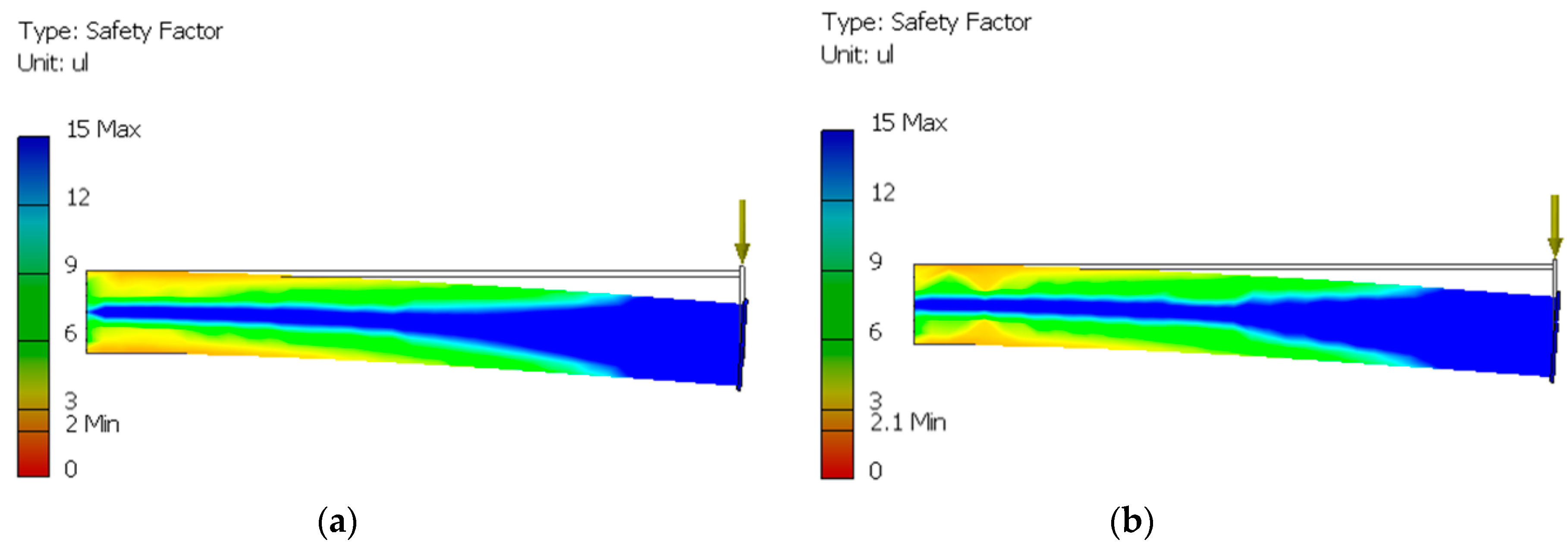
5.1.9. Safety Factor Appraisal

Realizing SF constraint for pressure vessels, new and aged models of the proposed scheme were analyzed regarding SF degradation. For said purpose, straight and bended enclosure segments were considered while dimensional specification and bending were determined on the basis of Section 5.1.1 and Section 5.1.7. Analysis revealed that new model of PE 100 enclosure had a SF of above 2, regarding straight and bended enclosure segments. Moreover, analysis unveiled that SF reduced by approximately 20 percent and 23 percent for the 25 year-aged similar enclosure model, regarding straight and bended enclosure segments respectively. However, SF in case of aged model remained above two regarding straight segment, while it fell only 15 percent below two regarding bended segment. Figure 14 shows the SF of new and aged models of the proposed scheme regarding straight and bended enclosure segments.

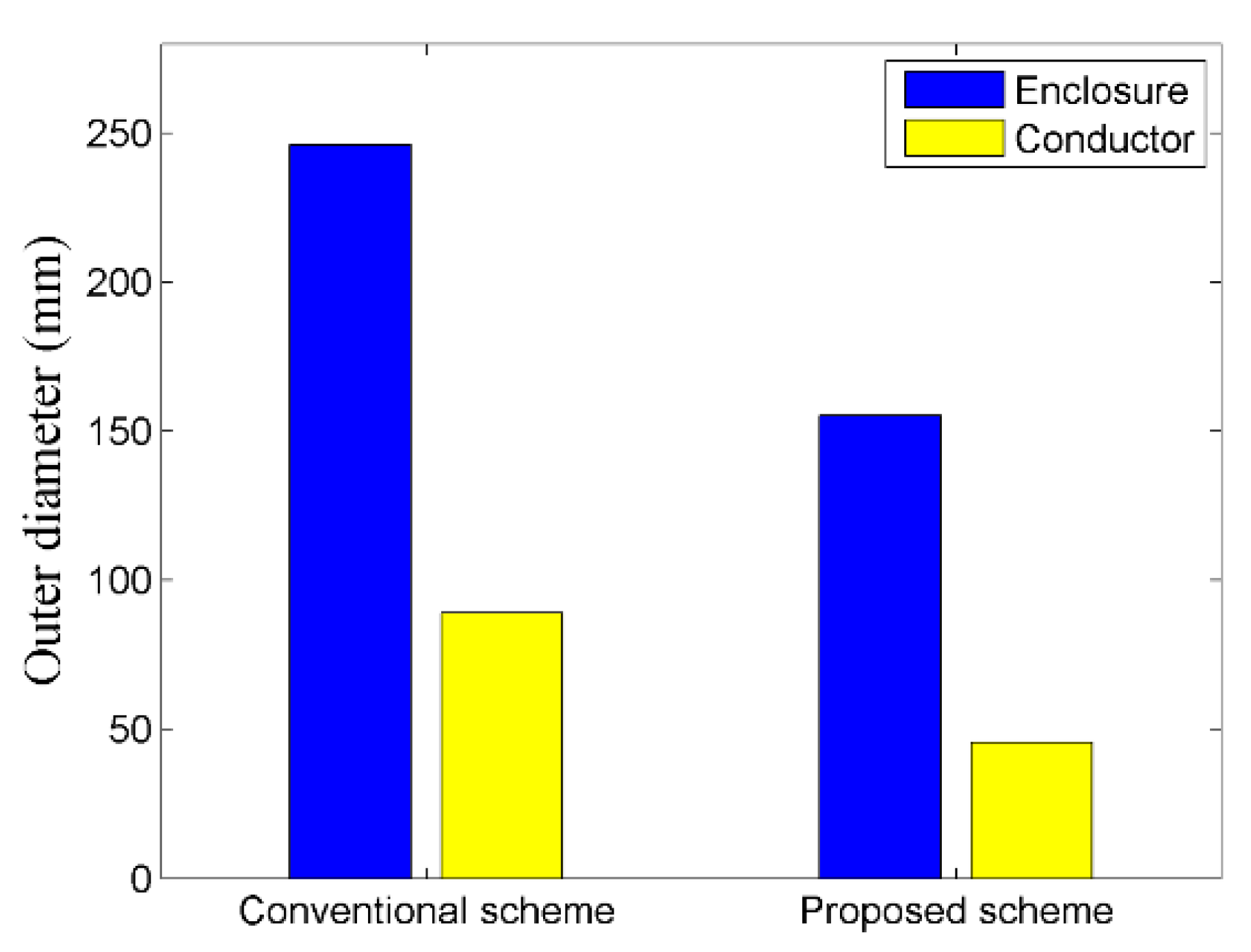
5.1.10. Dimensional Comparison

In order to analyze dimensional variation, FGIL comprising of proposed a PE 100 enclosure was compared with the conventional scheme. Detailed comparison revealed that enclosure thickness of proposed thermoplastic enclosure was approximately 4 mm larger than the conventional scheme. However, a reduced conductor diameter necessitates reduced enclosure diameter in order to achieve the required FUF for FGIL. Thus, overall size of FGIL was reduced by approximately 90 mm in comparison to the conventional scheme. Figure 15 shows the dimensional comparison of FGIL comprising of proposed thermoplastic enclosure and stranded conductor with the conventional GIL scheme.

5.2. Electrical Aspects

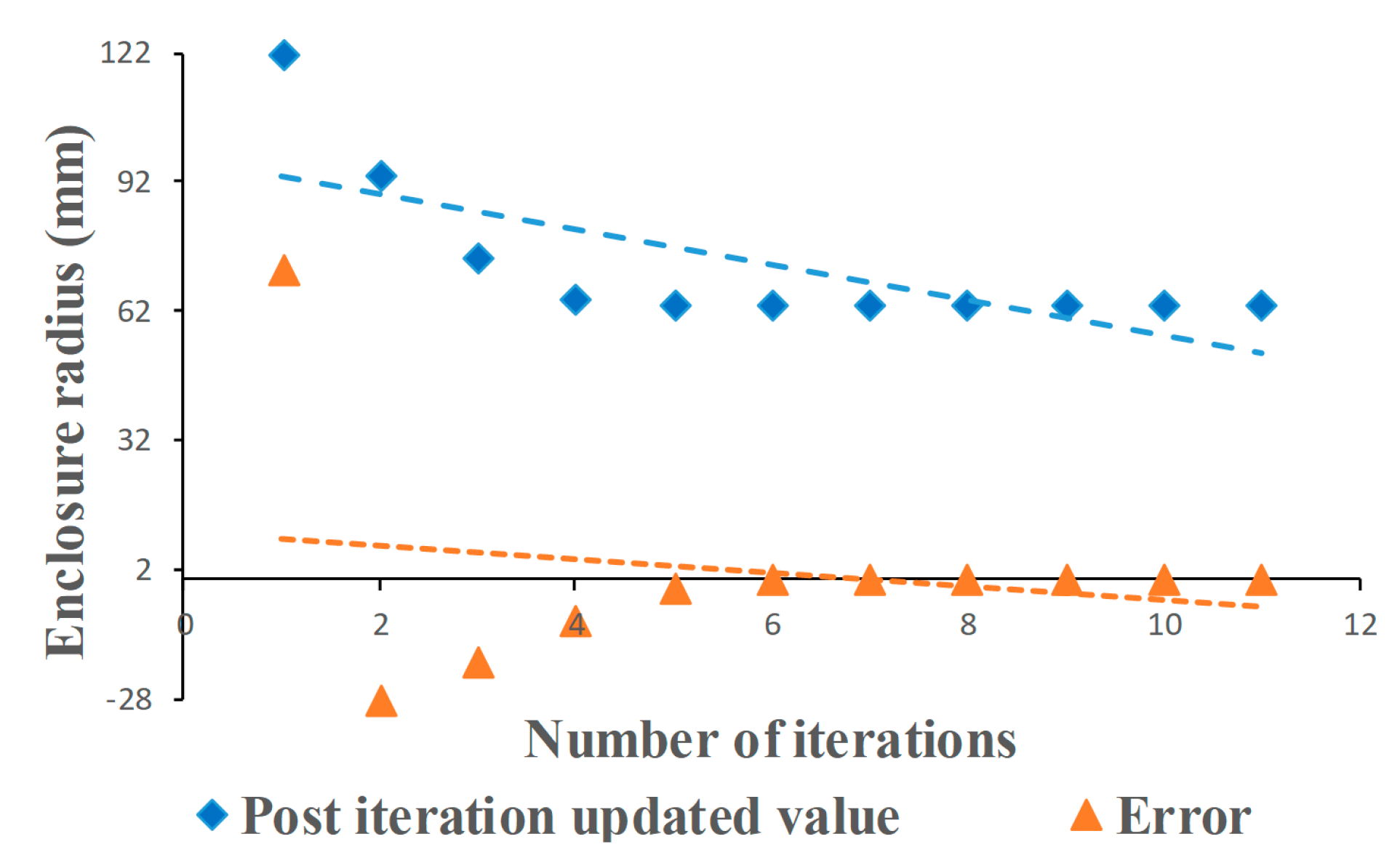
5.2.1. Dimensional Optimization Regarding FUF

Dimensional specifications of the proposed PE 100 enclosure, as evaluated in Section 5.1.1, were reconsidered, regarding the permissible FUF as described in Section 3.2.1. Figure 16 shows the results of the iterative technique implemented in Section 3.2.1. Dashed lines in Figure 16 shows that the estimated parameter as well as its error converged to the required accuracy in eleven iterations. Dimensional analysis revealed that the estimated enclosure size was almost thrice the conductor size, which ultimately resulted in acquiring FUF for the proposed scheme within the permissible range for GIL.

5.2.2. Electrode Gap Comparison

Based upon electro-mechanically optimized dimensions, finalized in Section 5.1.1 and Section 5.2.1, Figure 17 compares the electrode gap of proposed and conventional schemes regarding a 132 kV transmission line. Implementation of stranded conductor in FGIL reduced the conductor’s diameter by approximately 50 percent as compared to the conventional hollow conductor. Moreover, dependence of electrode gap upon FUF reduced the diameter of ground electrode of FGIL by approximately 43 percent in comparison to the conventional scheme. Thus, critical analysis of Figure 15, Figure 16 and Figure 17 revealed that the electrode gap for PE 100 based FGIL reduced by approximately 41 percent in comparison to the conventional scheme.

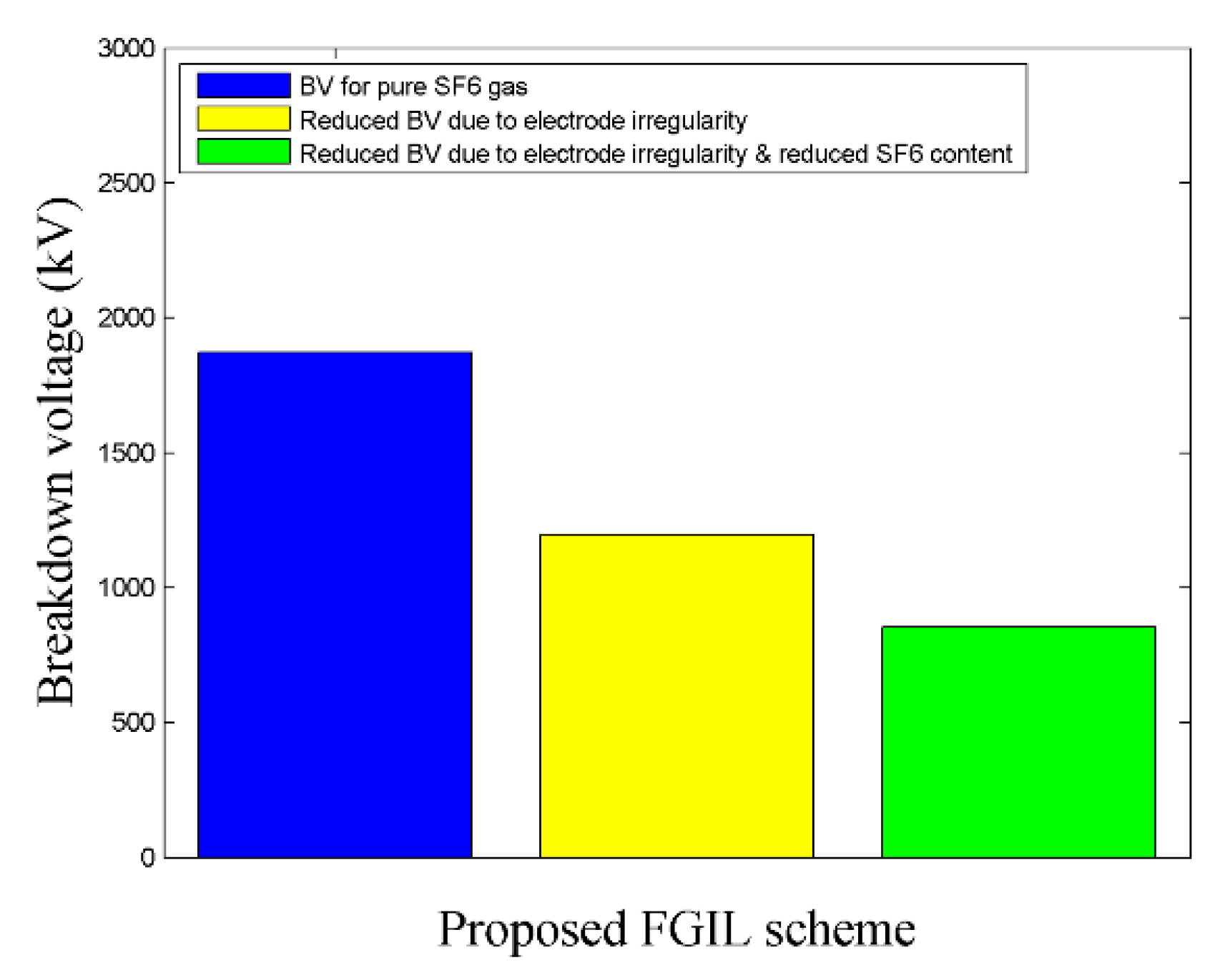
5.2.3. Breakdown Voltage Appraisal

Based upon the optimized dimensional specifications determined in Section 5.1.1 and Section 5.2.1, BV analysis for the proposed PE 100 enclosure based FGIL was performed as per the scheme described in Section 3.2.2 and Section 3.2.3. Figure 18 represents the BV for pure SF6 along with its possible degradation, due to electrode irregularity, as well as the reduced SF6 content. Further, Figure 19 compares the design, operational and critical electric fields for the proposed scheme. Critical analysis of Figure 18 and Figure 19 revealed that dimensional specifications, determined in Section 5.1.1 and Section 5.2.1, which resulted in achieving the required BV and field characteristics for the proposed scheme, as per the standards for gas insulated equipment.

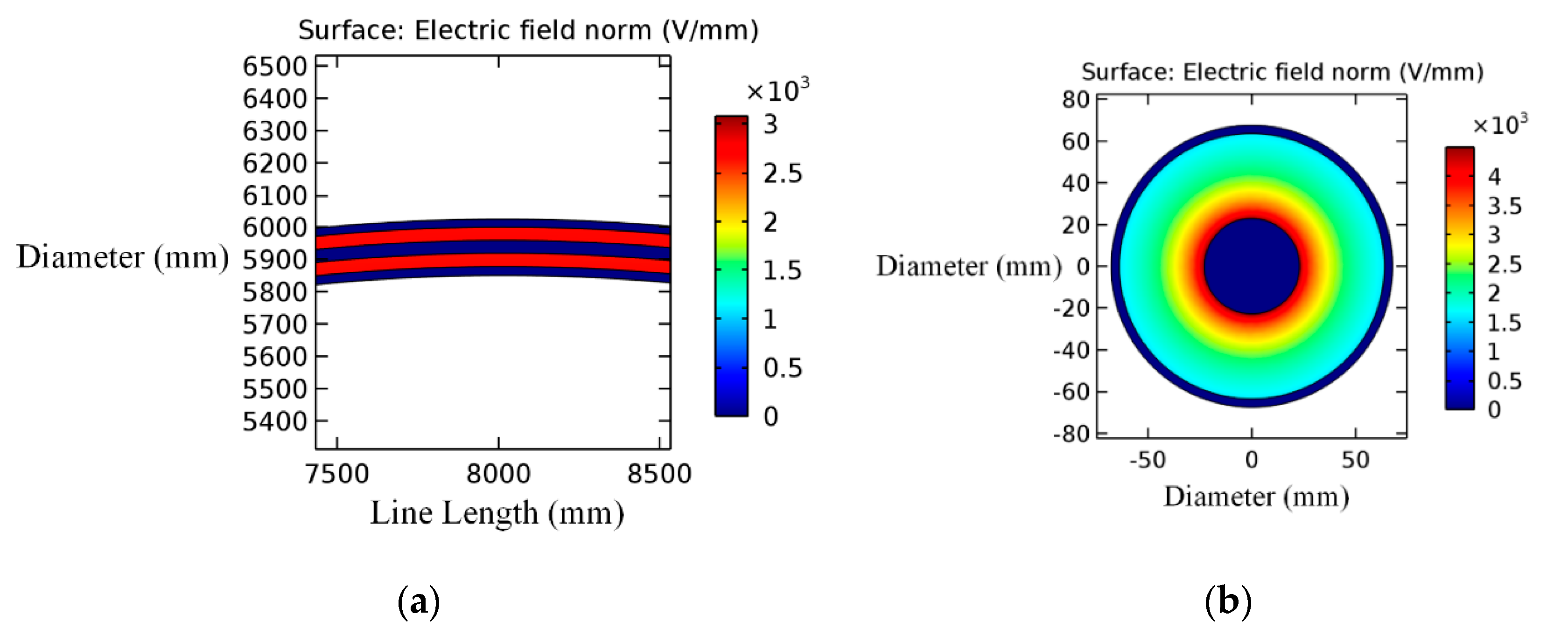
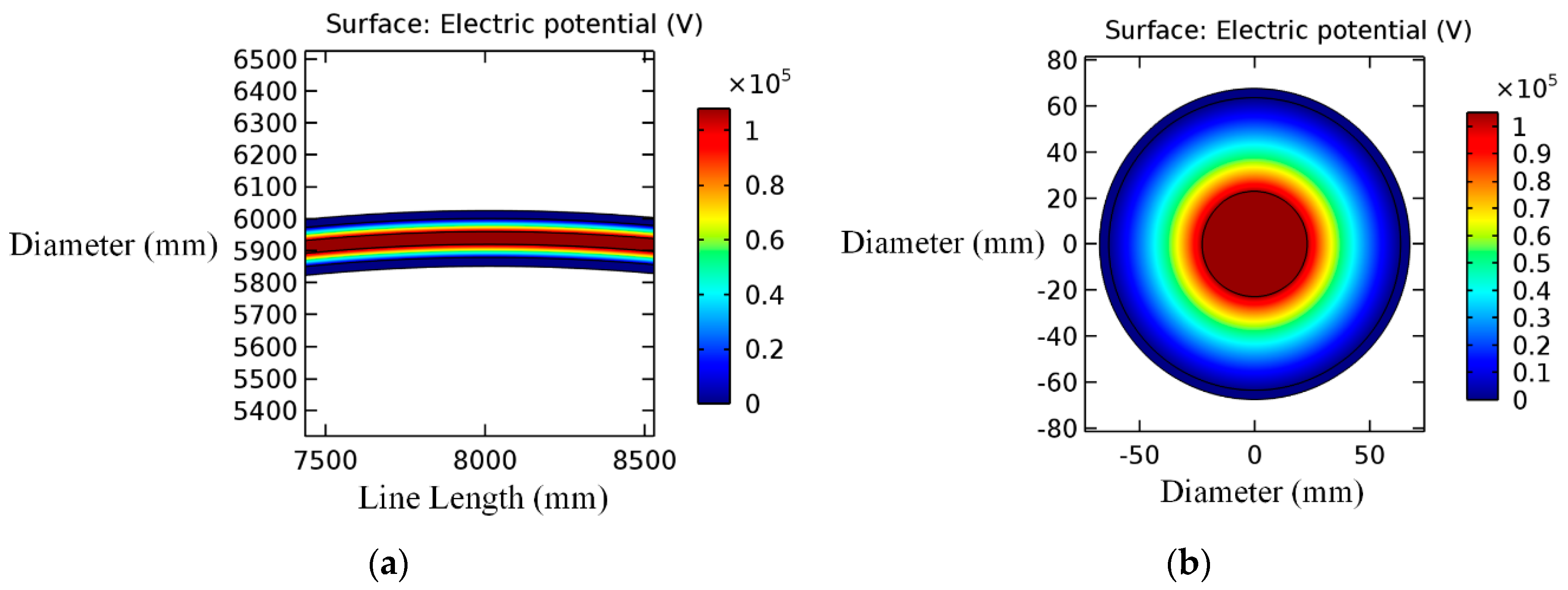
5.2.4. Field Stress Distribution Regarding Bended Segments

Concerning field stress distribution in the bended segment of proposed scheme, simulation regarding electrostatic stress distribution in straight and bended FGIL models was performed. For this purpose, Autodesk Inventor based 20 meters long bent and straight models of FGIL were developed. Moreover, COMSOL Multiphysics was used to analyze the FUF and stress distribution regarding both developed models. Bending of FGIL was performed as per the permissible MLBR limit of PE 100 enclosure, and FUF, as well as field distribution analysis for the respective FGIL models, was performed apropos radial and axial cross-sections. Comparison of straight and bent FGIL models apropos axial cross-section showed a minimal deviation of 0.8 percent and 0.7 percent in FUF and field intensity respectively. Furthermore, detailed appraisal of the two FGIL models apropos radial cross-section revealed a trivial deviance of 0.5 percent and 0.4 percent in FUF and field intensity respectively. Trivial deviation was observed due to the fact that enclosure bending as per MLBR limits resulted in gradual bending, as well as insignificant circumferential deformation of bended FGIL model. Thus, field utilization, stress distribution and field intensity for bended FGIL model remained nearly the same as compared to the straight FGIL model. Figure 20a,b shows the field distribution regarding axial and radial cross-sections of bended FGIL model respectively. Further, Figure 21a,b shows the potential distribution regarding axial and radial cross-sections of bended FGIL model respectively.

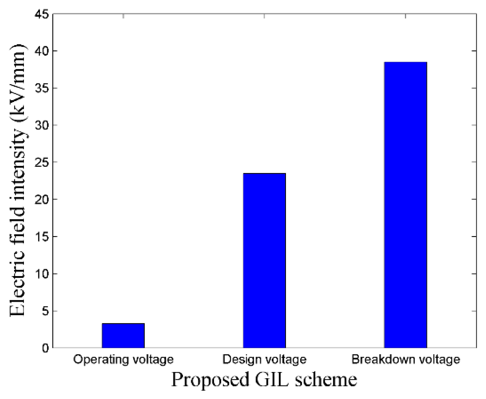
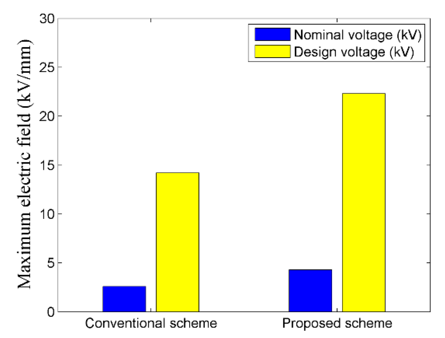
5.2.5. Field Intensity Comparison

Concerning the effectiveness of field intensity upon dielectric degradation, field intensity regarding nominal and design voltages of proposed scheme was analyzed in comparison to the conventional GIL scheme, as well as the permissible standard values. For the said purpose, COMSOL Multiphysics based GIL models of conventional and proposed scheme were developed. Comparison revealed that field intensity of the proposed scheme was approximately 1.7 times higher in comparison to the conventional scheme regarding nominal and design voltages. However, despite this increase, field intensity for the proposed scheme regarding nominal and design voltages was approximately 1.4 times lesser than their respective permissible limits of 4.5 kV/mm and 20 kV/mm as specified for GIL. Figure 22 compares the field intensity regarding nominal and design voltages of 132 kV conventional and proposed GIL schemes.

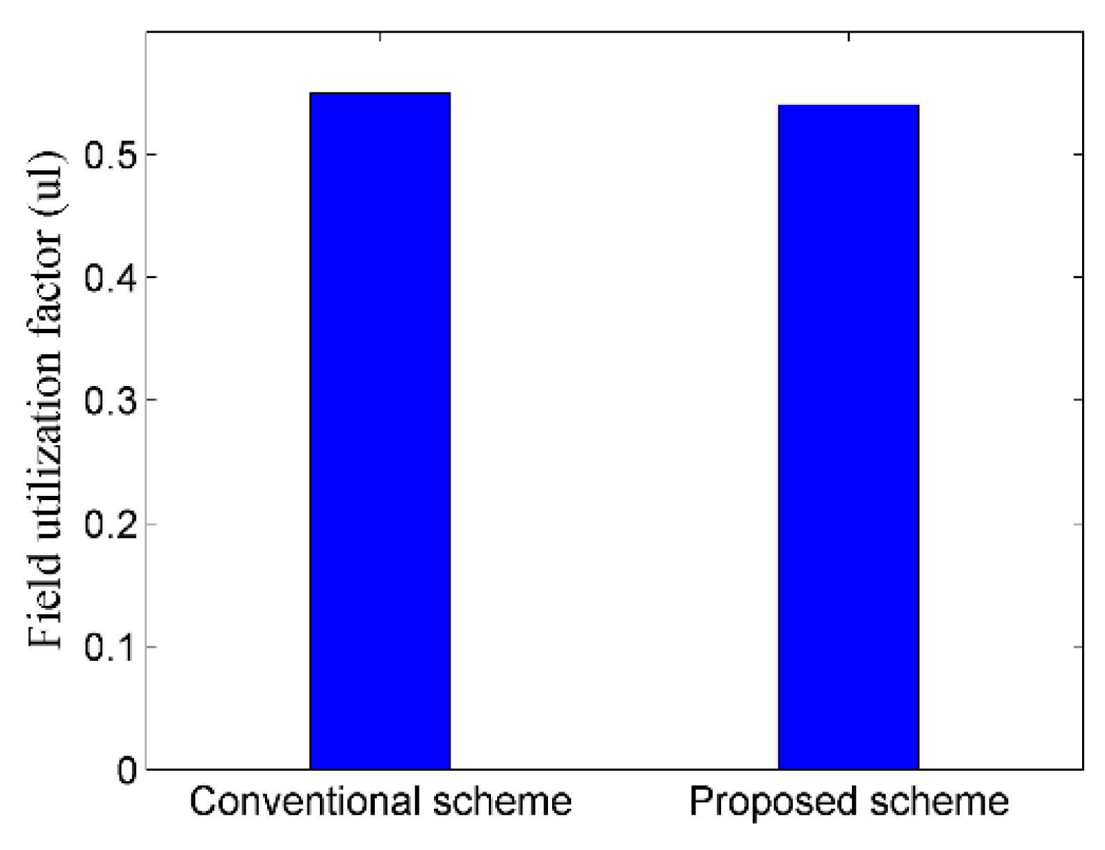
5.2.6. FUF Appraisal

Concerning the field utilization constraint for GIL, FUF for proposed PE 100 enclosure based FGIL was analyzed in comparison to the conventional GIL, as well as the allowable standard range. For the said purpose, COMSOL Multiphysics based GIL models of conventional and proposed schemes were developed. Comparison revealed that FUF for the proposed scheme deviated the FUF for conventional scheme by 1.8 percent only. Moreover, FUF for the proposed scheme lies well within the permissible standard range of 0.5 to 0.6 for GIL. Figure 23 compares the FUF for conventional and proposed GIL schemes.

6. Conclusions

Conventional GIL is comprised of a rigid metallic enclosure, which curtails its application perspectives in metropolitan vicinities, due to its intrinsic larger bending radius and lay length along with the requirement of trench development. In this research, a flexible-thermoplastic-enclosure is proposed for GIL, in order to simplify the intricacies associated with conventional GIL due to its structural rigidity. In addition, comprehensive design for the proposed scheme regarding electro-mechanical aspects, along with a detailed analysis apropos its new and aged models is performed, in comparison to the conventional scheme.
Analytical and simulation results regarding new and aged models revealed that PE 100 based enclosure for FGIL, with optimized dimensional specifications as determined in this research, exhibits the required electrostatic and dielectric characteristics for FGIL, regarding straight and bent segments. Electric field of FGIL was observed to be approximately 1.74 times higher in comparison to the conventional GIL. Although, this field magnitude lies within the permissible limits, critical consideration is essentially required for the SF regarding operating and design voltages of FGIL.
Analysis also revealed that, both new and aged models of PE 100 based enclosure of FGIL, have the required stress bearing characteristics in comparison to the conventional GIL scheme. Moreover, the proposed scheme also resulted in a significant reduction in bending radius, lay length and dimensional specifications of FGIL, compared to the conventional GIL. Reduced MLBR and lay length will facilitate the trenchless underground cable laying through HDD, which will be highly beneficial for metropolitan applications, and will significantly reduce the project’s cost as well as its implementation duration.
Thus, PE 100 enclosure, being flexible and having the required stress bearing characteristics, is a potential candidate regarding the curtailment of complexities, associated with metropolitan applications of high-voltage transmission lines, as well as conventional GIL, due to its structural rigidity.

Author Contributions

Conceptualization, T.I. and A.A.Q.; data curation, M.J.A. and R.u.H.; formal analysis, M.J.A., A.A. and R.u.H.; investigation, M.J.A.; methodology, M.J.A.; project administration, T.I. and A.A.Q.; software, M.J.A. and A.A.; writing—original draft, M.J.A.; writing—review and editing, T.I., A.A.Q. and R.u.H.

Funding

This research received no external funding.

Acknowledgments

The authors acknowledge the technical support provided by the electrical engineering department and Polymer engineering department of University of Engineering and Technology, Lahore, Pakistan, during this research work.

Conflicts of Interest

The authors declare no conflicts of interest.

References

  1. Adedeji, K.; Ponnle, A.; Abe, B.; Jimoh, A. Effect of increasing energy demand on the corrosion rate of buried pipelines in the vicinity of high voltage overhead transmission lines. In Proceedings of the 2015 Intl Aegean Conference on Electrical Machines & Power Electronics (ACEMP), 2015 Intl Conference on Optimization of Electrical & Electronic Equipment (OPTIM) & 2015 Intl Symposium on Advanced Electromechanical Motion Systems (ELECTROMOTION), Side, Turkey, 2–4 September 2015; pp. 299–303. [Google Scholar]
  2. Sardaro, R.; Bozzo, F.; Fucilli, V. High-voltage overhead transmission lines and farmland value: Evidences from the real estate market in Apulia, southern Italy. Energy Policy 2018, 119, 449–457. [Google Scholar] [CrossRef]
  3. Wiedemann, P.M.; Boerner, F.; Claus, F. How far is how far enough? Safety perception and acceptance of extra-high-voltage power lines in Germany. J. Risk Res. 2018, 21, 463–479. [Google Scholar] [CrossRef]
  4. Fan, F.; Wu, G.; Wang, M.; Cao, Q.; Yang, S. Robot delay-tolerant sensor network for overhead transmission line monitoring. Appl. Sci. 2018, 8, 847. [Google Scholar] [CrossRef]
  5. Neureiter, C.; Engel, D.; Uslar, M. Domain Specific and Model Based Systems Engineering in the Smart Grid as Prerequesite for Security by Design. Electronics 2016, 5, 24. [Google Scholar] [CrossRef]
  6. Gautam, B.R.; Li, F.; Ru, G. Assessment of urban roof top solar photovoltaic potential to solve power shortage problem in Nepal. Energy Build. 2015, 86, 735–744. [Google Scholar] [CrossRef]
  7. Hajeforosh, S.; Pooranian, Z.; Shabani, A.; Conti, M. Evaluating the high frequency behavior of the modified grounding scheme in wind farms. Appl. Sci. 2017, 7, 1323. [Google Scholar] [CrossRef]
  8. Kamal, T.; Karabacak, M.; Hassan, S.Z.; Fernández-Ramírez, L.M.; Riaz, M.H.; Riaz, M.T.; Khan, M.A.; Khan, L. Energy management and switching control of PHEV charging stations in a hybrid smart micro-grid system. Electronics 2018, 7, 156. [Google Scholar] [CrossRef]
  9. Xu, K.; Zhang, X.; Chen, Z.; Wu, W.; Li, T. Risk assessment for wildfire occurrence in high-voltage power line corridors by using remote-sensing techniques: A case study in Hubei Province, China. Int. J. Remote Sens. 2016, 37, 4818–4837. [Google Scholar] [CrossRef]
  10. Sun, C.-C.; Liu, C.-C.; Xie, J. Cyber-physical system security of a power grid: State-of-the-art. Electronics 2016, 5, 40. [Google Scholar] [CrossRef]
  11. Benato, R.; Sessa, S.D.; Guizzo, L.; Rebolini, M. Saving environmental impact of electrical energy transmission by employing existing/planned transport corridors. In Proceedings of the 2017 IEEE International Conference on Environment and Electrical Engineering and 2017 IEEE Industrial and Commercial Power Systems Europe (EEEIC/I&CPS Europe), Milan, Italy, 6–9 June 2017; pp. 1–6. [Google Scholar]
  12. Benato, R.; Sessa, S.D.; Guizzo, L.; Rebolini, M. Synergy of the future: High voltage insulated power cables and railway-highway structures. IET Gener. Transm. Distrib. 2017, 11, 2712–2720. [Google Scholar] [CrossRef]
  13. Kukharchuk, I.; Kazakov, A.; Trufanova, N. Investigation of heating of 150 kV underground cable line for various conditions of laying. In Proceedings of the IOP Conference Series: Materials Science and Engineering, Tomsk, Russia, 4–6 December 2017; p. 022041. [Google Scholar]
  14. Salata, F.; Nardecchia, F.; de Lieto Vollaro, A.; Gugliermetti, F. Underground electric cables a correct evaluation of the soil thermal resistance. Appl. Therm. Eng. 2015, 78, 268–277. [Google Scholar] [CrossRef]
  15. Zhao, H.; Zhang, W.; Wang, Y. Characteristic impedance analysis of medium-voltage underground cables with grounded shields and armors for power line communication. Electronics 2019, 8, 571. [Google Scholar] [CrossRef]
  16. Lauria, D.; Quaia, S. Technical comparison between a gas-insulated line and a traditional three-bundled OHL for a 400 kV, 200 km connection. In Proceedings of the 2015 International Conference on Clean Electrical Power (ICCEP), Taormina, Italy, 16–18 June 2015; pp. 597–601. [Google Scholar]
  17. Wang, M.; Wu, G.; Fan, F.; Ji, Q.; He, W.; Cao, Q. Dynamic network topology control of branch-trimming robot for transmission lines. Electronics 2019, 8, 549. [Google Scholar] [CrossRef]
  18. Magier, T.; Tenzer, M.; Koch, H. Direct current gas-insulated transmission lines. IEEE Trans. Power Deliv. 2018, 33, 440–446. [Google Scholar] [CrossRef]
  19. Magier, T.; Dehler, A.; Koch, H. AC Compact High Power Gas-Insulated Transmission Lines. In Proceedings of the 2018 IEEE/PES Transmission and Distribution Conference and Exposition (T&D), Denver, CO, USA, 16–19 April 2018; pp. 1–5. [Google Scholar]
  20. Koch, H.; Goll, F.; Magier, T.; Juhre, K. Technical aspects of gas insulated transmission lines and application of new insulating gases. IEEE Trans. Dielectr. Electr. Insul. 2018, 25, 1448–1453. [Google Scholar] [CrossRef]
  21. Widger, P.; Haddad, A. Evaluation of SF6 leakage from gas insulated equipment on electricity networks in Great Britain. Energies 2018, 11, 2037. [Google Scholar] [CrossRef]
  22. Mueller, C.E.; Keil, S.I.; Bauer, C. Effects of spatial proximity to proposed high-voltage transmission lines: Evidence from a natural experiment in Lower Saxony. Energy Policy 2017, 111, 137–147. [Google Scholar] [CrossRef]
  23. Crespi, C.M.; Vergara, X.P.; Hooper, C.; Oksuzyan, S.; Wu, S.; Cockburn, M.; Kheifets, L. Childhood leukaemia and distance from power lines in California: A population-based case-control study. Br. J. Cancer 2016, 115, 122. [Google Scholar] [CrossRef]
  24. Brinkley, C.; Leach, A. Energy next door: A meta-analysis of energy infrastructure impact on housing value. Energy Res. Soc. Sci. 2019, 50, 51–65. [Google Scholar] [CrossRef]
  25. Koch, H. Gas Insulated Transmission Lines (GIL); John Wiley & Sons: Hoboken, NJ, USA, 2011. [Google Scholar]
  26. McDonald, J.D. Electric Power Substations Engineering; CRC Press: Boca Raton, FL, USA, 2012. [Google Scholar]
  27. Zarchi, D.A.; Vahidi, B. Optimal placement of underground cables to maximize total ampacity considering cable lifetime. IET Gener. Transm. Distrib. 2016, 10, 263–269. [Google Scholar] [CrossRef]
  28. Shabangu, T.; Shrivastava, P.; Abe, B.; Adedeji, K.; Olubambi, P. Influence of AC interference on the cathodic protection potentials of pipelines: Towards a comprehensive picture. In Proceedings of the 2017 IEEE AFRICON, Cape Town, South Africa, 18–20 September 2017; pp. 597–602. [Google Scholar]
  29. Tenzer, M.; Koch, H.; Imamovic, D. Underground transmission lines for high power AC and DC transmission. In Proceedings of the 2016 IEEE/PES Transmission and Distribution Conference and Exposition (T&D), Dallas, TX, USA, 2–5 May 2016; pp. 1–4. [Google Scholar]
  30. Zhou, T. Study on mechanical properties of transmission pipe materials. In Proceedings of the IOP Conference Series: Materials Science and Engineering, Sanya, China, 10–11 November 2018; p. 012090. [Google Scholar]
  31. Chakir, A.; Koch, H. Seismic calculations of directly buried gas-insulated transmission lines (GIL). In Proceedings of the IEEE/PES Transmission and Distribution Conference and Exhibition, Yokohama, Japan, 6–10 October 2002; pp. 1026–1029. [Google Scholar]
  32. Imamovic, D.T.; Tenzer, M.; Koch, H. High power underground transmission lines. In Proceedings of the 9th International Conference on Insulated Power Cables France, Versailles, France, 21–25 June 2015. [Google Scholar]
  33. Chakir, A.; Koch, H. Corrosion protection for gas-insulated transmission lines. In Proceedings of the IEEE Power Engineering Society Summer Meeting, Chicago, IL, USA, 21–25 July 2002; pp. 220–224. [Google Scholar]
  34. Wang, K.; Liu, K.; Song, X.; Zhang, J.; Lu, G. Design and test of 2250 kV semi-flexible SF6 insulated high voltage pulse transmission line. In Proceedings of the 2012 IEEE International Power Modulator and High Voltage Conference (IPMHVC), San Diego, CA, USA, 3–7 June 2012; pp. 683–686. [Google Scholar]
  35. Alvi, M.; Izhar, T.; Qaiser, A. Proposed scheme of pliable gas insulated transmission line and its comparative appraisal regarding electrostatic and dielectric aspects. Electronics 2018, 7, 328. [Google Scholar] [CrossRef]
  36. Thomas, H.; Marian, A.; Chervyakov, A.; Stückrad, S.; Salmieri, D.; Rubbia, C. Superconducting transmission lines–Sustainable electric energy transfer with higher public acceptance? Renew. Sustain. Energy Rev. 2016, 55, 59–72. [Google Scholar] [CrossRef]
  37. Jianying, Z.; Yujing, G.; Guangyao, J.; Liping, D. Research on the key technology of 1100 kV SF 6 gas-insulated metal-enclosed transmission line. In Proceedings of the 2017 4th International Conference on Electric Power Equipment-Switching Technology (ICEPE-ST), Xi’an, China, 22–25 October 2017; pp. 30–33. [Google Scholar]
  38. Guo, J.; Chen, H. Research on horizontal directional drilling locating technology based on seismic interference. In Proceedings of the 2019 Symposium on Piezoelectrcity, Acoustic Waves and Device Applications (SPAWDA), Harbin, China, 11–14 January 2019; pp. 1–4. [Google Scholar]
  39. Wang, Y.; Wen, G.; Chen, H. Horizontal directional drilling-length detection technology while drilling based on bi-electro-magnetic sensing. Sensors 2017, 17, 967. [Google Scholar] [CrossRef] [PubMed]
  40. Bascom, E.C.R.; Rezutko, J. Novel installation of a 138kv pipe-type cable system under water using horizontal directional drilling. In Proceedings of the 2014 IEEE PES T&D Conference and Exposition, Chicago, IL, USA, 14–17 April 2014; pp. 1–5. [Google Scholar]
  41. Alvi, M.J.; Izhar, T.; Qaiser, A.A.; Kharal, H.S.; Safdar, A. Field optimization and electrostatic stress reduction of proposed conductor scheme for pliable gas-insulated transmission lines. Appl. Sci. 2019, 9, 2988. [Google Scholar] [CrossRef]
  42. Alvi, M.J.; Izhar, T.; Qaiser, A.A.; Afzaal, M.U.; Anjum, A.; Safdar, A. Pliability assay of conventional gas insulated transmission line and flexible gas insulated transmission line regarding horizontal directional drilling based underground cable laying for metropolitan areas. In Proceedings of the 2018 IEEE International Conference on Environment and Electrical Engineering and 2018 IEEE Industrial and Commercial Power Systems Europe (EEEIC/I&CPS Europe), Palermo, Italy, 12–15 June 2018; pp. 1–5. [Google Scholar]
  43. Li, Y.; Liu, W.; Ren, X. Critical stress of high-density polyethylene during stress and photo-oxidative aging. Polym. Eng. Sci. 2015, 55, 2277–2284. [Google Scholar] [CrossRef]
  44. Weingrill, H.; Resch-Fauster, K.; Lucyshyn, T.; Zauner, C. High-density polyethylene as phase-change material: Long-term stability and aging. Polym. Test. 2019, 76, 433–442. [Google Scholar] [CrossRef]
  45. Hu, W.; Liu, W.; Ren, X. The study on aging behaviors and critical stress of cross-linked high-density polyethylene during stress and photo-oxidative aging. J. Polym. Res. 2019, 26, 114. [Google Scholar] [CrossRef]
  46. Becerra, A.; d’Almeida, J. UV effects on the tensile and creep behaviour of HDPE. Polym. Polym. Compos. 2017, 25, 327–332. [Google Scholar] [CrossRef]
  47. Zhao, B.; Zhang, S.; Sun, C.; Guo, J.; Yu, Y.; Xu, T. Aging behaviour and properties evaluation of high-density polyethylene (HDPE) in heating-oxygen environment. In Proceedings of the IOP Conference Series: Materials Science and Engineering, Kitakyushu City, Japan, 10–13 April 2018; p. 012021. [Google Scholar]
  48. Fairbrother, A.; Hsueh, H.-C.; Kim, J.H.; Jacobs, D.; Perry, L.; Goodwin, D.; White, C.; Watson, S.; Sung, L.-P. Temperature and light intensity effects on photo degradation of high-density polyethylene. Polym. Degrad. Stab. 2019, 165, 153–160. [Google Scholar] [CrossRef]
  49. Dai, J.; Yan, H.; Yang, J.J.; Guo, J.J. Evaluation of the aging behavior of high density polyethylene in thermal oxidative environment by principal component analysis. Key Eng. Mater. 2017, 727, 447–449. [Google Scholar] [CrossRef]
  50. Barsoum, I.; Barsoum, Z.; Islam, D. Thermo-mechanical evaluation of the performance and integrity of a HDPE stub-end bolted flange connection. J. Press. Vessel Technol. 2019, 141, 051206. [Google Scholar] [CrossRef]
  51. Mahl, M.; Jelich, C.; Baier, H. Thermo-mechanical behavior of polyethylene under mechanical loads at cryogenic and elevated temperatures. Int. J. Press. Vessel. Pip. 2017, 150, 11–18. [Google Scholar] [CrossRef]
  52. Merah, N.; Saghir, F.; Khan, Z.; Bazoune, A. Effect of temperature on tensile properties of HDPE pipe material. Plast. Rubber Compos. 2006, 35, 226–230. [Google Scholar] [CrossRef]
  53. SIMONA. Engineering Manual for Piping Systems; SIMONA: Kirn, Germany, 2010. [Google Scholar]
  54. DIN 8075. Polyethylene (PE) Pipes—PE 80, PE 100—General Quality Requirements, Testing; German Institute for Standardization: Berlin, Germany, 2018. [Google Scholar]
  55. DIN 8074. Polyethylene (PE)—Pipes PE 80, PE 100—Dimensions; German Institute for Standardization: Berlin, Germany, 2011. [Google Scholar]
  56. Plastics Pipe Institute. TR-4/2018-PPI Listing of Hydrostatic Design Basis (HDB), Hydrostatic Design Stress (HDS), Strength Design Basis (SDB), Pressure Design Basis (PDB) and Minimum Required Strength (MRS) Ratings For Thermoplastic Piping Materials or Pipe; Plastics Pipe Institute: Irving, TX, USA, 2018. [Google Scholar]
  57. DIN-DVS 2205-1. Calculation of Tanks and Apparatus Made of Thermoplastics—Characteristic Values; German Institute of Standardization: Berlin, Germany, 2015. [Google Scholar]
  58. ISO 4437. Plastics Piping Systems for the Supply of Gaseous Fuels—Polyethylene (PE); International Organization for Standardization: Geneva, Switzerland, 2014. [Google Scholar]
  59. Plastics Pipe Institute. The Plastics Pipe Institute: Handbook of Polyethylene Pipe; Plastics Pipe Institute: Irving, TX, USA, 2006. [Google Scholar]
  60. American Water Works Association. Manual M55: PE Pipe—Design and Installation, 1st ed.; American Water Works Association: Denver, CO, USA, 2006. [Google Scholar]
  61. Performance Pipe. Driscopipe® 8100 Series Polyethylene Piping Produced from PE 4710-PE 100 Material; Performance Pipe: Plano, TX, USA, 2006. [Google Scholar]
  62. WL Plastics. HDPE Pressure Pipe—Determining Pressure Ratings for Applications. Available online: www.wlplastics.com (accessed on 26 July 2019).
  63. Performance Pipe. Technical Note-PP 816-TN PE3608 & PE4710 Materials Designation Codes and Pipe Pressure Ratings; Performance Pipe: Plano, TX, USA, 2011. [Google Scholar]
  64. Palermo, G. Comparison Between PE 4710 (PE 4710 PLUS) and PE 100 (PE 100+, PE 100 RC). Plastic Pipe Institute: Dallas, TX, USA. Available online: http://www.plasticspipe.com/docs/41 (accessed on 26 July 2019).
  65. ASTM D2837. Standard Test Method for Obtaining Hydrostatic Design Basis for Thermoplastic Pipe Materials or Pressure Design Basis for Thermoplastic Pipe Products; ASTM Intl.: West Conshohocken, PA, USA, 2011. [Google Scholar]
  66. ISO 9080:2012. Plastics Piping and Ducting Systems—Determination of the Long-Term Hydrostatic Strength of Thermoplastics Materials in Pipe Form by Extrapolation; International Organization of Standardization: Geneva, Switzerland, 2012. [Google Scholar]
  67. Chen, L.; Griffiths, H.; Haddad, A.; Kamarudin, M. Breakdown of cf 3 i gas and its mixtures under lightning impulse in coaxial-GIL geometry. IEEE Trans. Dielectr. Electr. Insul. 2016, 23, 1959–1967. [Google Scholar] [CrossRef]
  68. Chen, L.; Widger, P.; Kamarudin, M.S.; Griffiths, H.; Haddad, A. CF3I gas mixtures: Breakdown characteristics and potential for electrical insulation. IEEE Trans. Power Deliv. 2016, 32, 1089–1097. [Google Scholar] [CrossRef]
  69. Malik, N.H.; Al-Arainy, A.; Qureshi, M.I. Electrical Insulation in Power Systems; Marcel Dekker: New York, NY, USA, 1998. [Google Scholar]
  70. Li, X.; Zhao, H.; Jia, S.; Murphy, A.B. Study of the dielectric breakdown properties of hot SF6–CF4 mixtures at 0.01–1.6 MPa. J. Appl. Phys. 2013, 114, 053302. [Google Scholar] [CrossRef]
  71. DriscoPlex® 6300 PE4710 Pipe. Available online: www.performancepipe.com (accessed on 27 July 2019).
  72. Auansakul, C. High Temperature Polyethylene (PE-RT) Thermal Distribution Application. In Proceedings of the International District Energy Association, Austin, TX, USA, 8–12 February 2016. [Google Scholar]
Figure 1. Schematic of flexible gas insulated line (FGIL).
Electronics 08 00929 g001
Figure 2. Flexibility analysis regarding specimen 2 of (a) PE 80 and (b) PE 100 as enlisted in Table 2.
Electronics 08 00929 g002
Figure 3. Safety factor (SF) appraisal apropos the flexibility analysis of specimens 2 of (a) PE 80 and (b) PE 100 as enlisted in Table 2.
Electronics 08 00929 g003
Figure 4. Flexibility comparison of different enclosure specimens described in Table 2.
Electronics 08 00929 g004
Figure 5. Longitudinal minimum bending radius (LMBR) comparison of different enclosure specimens described in Table 2.
Electronics 08 00929 g005
Figure 6. Flow chart of design algorithm for PE 100 based flexible-thermoplastic-enclosure of FGIL.
Electronics 08 00929 g006
Figure 7. Operating pressure comparison of PE 100 enclosure’s new and aged models with required operating pressure of FGIL.
Electronics 08 00929 g007
Figure 8. Comparison of PE 100 enclosure’s longitudinal deformations regarding temperature and pressure with their respective allowable limits.
Electronics 08 00929 g008
Figure 9. Buckling resistance comparison for new and aged models of PE 100 enclosure regarding their underground implementation.
Electronics 08 00929 g009
Figure 10. Comparison of permissible and actual wall compressive stress for the proposed scheme.
Electronics 08 00929 g010
Figure 11. Percentage ring deflection comparison for the proposed scheme regarding new and aged models.
Electronics 08 00929 g011
Figure 12. Minimum longitudinal bending radius (MLBR) comparison regarding loaded and unloaded models of proposed enclosure scheme based FGIL.
Electronics 08 00929 g012
Figure 13. Lay length comparison of proposed PE 100 based FGIL with the conventional gas insulated lines (GIL) scheme.
Electronics 08 00929 g013
Figure 14. Safety factor (SF) comparison of new and aged models of the proposed scheme regarding straight and bended enclosure segments.
Electronics 08 00929 g014
Figure 15. Dimensional comparison of FGIL comprising of proposed thermoplastic enclosure and stranded conductor with the conventional GIL scheme.
Electronics 08 00929 g015
Figure 16. Optimized enclosure dimension regarding the permissible field utilization factor (FUF).
Electronics 08 00929 g016
Figure 17. Electrode gap comparison between conventional and proposed GIL schemes.
Electronics 08 00929 g017
Figure 18. Breakdown voltage (BV) for pure SF6 in comparison to its reduction due to lesser SF6 content, as well as electrode irregularity.
Electronics 08 00929 g018
Figure 19. Electrostatic field comparison for suggested FGIL scheme regarding operating voltage, design voltage and BV.
Electronics 08 00929 g019
Figure 20. Electrostatic field distribution in bended segment of proposed PE 100 based FGIL scheme regarding (a) axial and (b) radial cross-sections.
Electronics 08 00929 g020
Figure 21. Potential distribution in bended segment of proposed PE 100 based FGIL scheme regarding (a) axial and (b) radial cross-sections.
Electronics 08 00929 g021
Figure 22. Field intensity comparison of conventional and proposed GIL schemes regarding nominal and design voltages.
Electronics 08 00929 g022
Figure 23. Field utilization factor comparison for conventional and proposed GIL schemes.
Electronics 08 00929 g023
Table 1. Detailed specifications of polyethylene (PE) variants.
Sr. No.ResinMinimum Required Strength (MRS) (MPa) (ISO 4437:2007)Density (g/cm3) (ISO 1183)Long Term Hydrostatic Strength (LTHS) (MPa) (ISO 4437:2007)Tensile Strength (TS) (MPa)
1.PE 636.30.947.4Low
2.PE 8080.959Moderate
3.PE 100100.9612.4High
Table 2. Detailed specifications of PE enclosure specimens used in the structural flexibility analysis.
Sr. No.ResinPressure Rating (Bar)Outer Diameter (mm)Dimension Ratio
1.PE 8085013
2.PE 80812513
3.PE 80825013
1.PE 10085017
2.PE 100812517
3.PE 100825017

