Article

A Novel Left-Turn Signal Control Method for Improving Intersection Capacity in a Connected Vehicle Environment

1
College of Transportation, Shandong University of Science and Technology, Qingdao 266590, China
2
Department of Civil & Environmental Engineering, University of Wisconsin-Madison, 1221 Engineering Hall,1415 Engineering Drive, Madison, WI 53706, USA
*
Author to whom correspondence should be addressed.
Electronics 2019, 8(9), 1058; https://doi.org/10.3390/electronics8091058
Submission received: 8 August 2019 / Revised: 10 September 2019 / Accepted: 16 September 2019 / Published: 19 September 2019

Abstract

:
Setting up an exclusive left-turn lane and corresponding signal phase for intersection traffic safety and efficiency will decrease the capacity of the intersection when there are less or no left-turn movements. This is especially true during rush hours because of the ineffective use of left-turn lane space and signal phase duration. With the advantages of vehicle-to-infrastructure (V2I) communication, a novel intersection signal control model is proposed which sets up variable lane direction arrow marking and turns the left-turn lane into a controllable shared lane for left-turn and through movements. The new intersection signal control model and its control strategy are presented and simulated using field data. After comparison with two other intersection control models and control strategies, the new model is validated to improve the intersection capacity in rush hours. Besides, variable lane lines and the corresponding control method are designed and combined with the left-turn waiting area to overcome the shortcomings of the proposed intersection signal control model and control strategy.

1. Introduction

Due to the rapid increase in population and the number of vehicles, traffic congestion has had a major impact on day-to-day life. Many scholars have done a great deal of research on improving traffic congestion, such as on bus priority strategies [1,2], mass rapid transit [3,4], parking management [5,6], intelligent transportation systems [7,8], etc. As an important component of intelligent transportation systems, the efficient operation of intersections has several advantages for the transportation in a city. At an at-grade intersection, the left-turn lane and its corresponding signal phase should be set when the left-turning vehicles are sufficient [9]. The purpose of this operation is to reduce traffic conflicts and improve safety. Figure 1a shows a traditional four-leg at-grade intersection model with an exclusive left-turn lane controlled by a fixed-time system, and the signal control phases are shown in Figure 1b. In this intersection model, there are three lanes on the main street: one exclusive left-turn lane, one through lane, one shared through-right lane. There are two lanes on the minor street: one exclusive left-turn lane and one shared through-right lane. The exclusive left-turn lane is only used for left-turning vehicles. In order to realize the establishment of the left-turn lane, there are clear lane direction arrow markings in each lane, marked on the surface of the lane. Once the lane direction arrow marking is set, it cannot be changed at any time. This paper calls it static lane direction arrow marking. It causes the spatial separation of left-turning vehicles from through vehicles. Simultaneously, this arrangement is usually equipped with a left-turn signal phase duration to temporally separate left-turning vehicles from through vehicles. This intersection model with static lane direction arrow markings is applied widely in many cities around the world.
This intersection model plays an important role in the safe passage of vehicles, but it cannot adapt to changes in traffic flow demand. For example, when there are fewer left-turning vehicles and more through vehicles, there will be congestion in the through lane, while the space of the exclusive left-turn lane will be wasted because through vehicles are forbidden in the exclusive left-turn lane. Irrespective of whether fixed-time control or an actuated traffic signal control are used at the intersection, it will cause the waste of left-turn phase duration and reduce the intersection’s capacity, especially in the rush hour, which intensifies the traffic congestion and increases the overall delay of the vehicles. In practice, this is very common. For example, during the period of people going to work or returning home in areas near downtown, most vehicles are moving in and out of the city, and there are few or sometimes even no left-turning vehicles. In this case, the exclusive left-turn lane will reduce the capacity of the intersection and seriously affect the traffic’s efficiency.
Therefore, this paper proposes a new intersection signal control model which changes the static lane direction arrow markings into variable lane direction arrow markings. The variable lane direction arrow markings can change with the number of vehicles, turning the exclusive left-turn lane into a controllable shared lane for left-turn and through movements. This can enable through vehicles to enter the controllable shared lane when there are fewer left-turning vehicles in the left-turn lane, thus solving the problem of wasting space in the exclusive left-turn lane. In addition, with the advantages of vehicle-to-infrastructure (V2I) communication, a control strategy is proposed for the new intersection signal control model which is based on a fixed-time control strategy and can solve the problem of full utilization of the green phase in the controllable shared lane. This provides the intersection with a better ability to adapt to changes in lane traffic flow, and thereby improves the intersection’s capacity. The proposed intersection signal control model and control strategy were verified with the VISSIM simulator and analyzed in detail.
The rest of the paper is organized as follows. In Section 2, the research status of intersection signal control is discussed. Section 3 presents the new intersection signal control model and control principle. Section 4 proposes the new intersection signal control strategy. Numerical examples are presented and discussed for demonstration of the proposed intersection control model and algorithm in Section 5. Finally, Section 6 presents a brief conclusion and recommendations for future work.

2. Literature Review

In view of ameliorating the problem of the exclusive left-turn lane at intersections, several measures and treatments have been conceived, studied, and implemented. Hummer earlier summarized seven types of unconventional alternatives: median U-turn, bowtie, superstreet, paired intersections, jughandle, continuous flow intersection (CFI), and continuous green T; the pros and cons of each are described [10,11]. Other designs have also been proposed, such as the split intersection [12], USC intersection [13,14], paraflow intersection [15], etc. The aforementioned measures for the treatment of left turns are generally called unconventional arterial intersection designs (UAIDs), which are summarized and compared with each other in [16,17,18,19]. Reference to increasing intersection capacity and safety or reducing the delay at the intersection, as well as describing their application, have been discussed or validated in [20,21,22,23,24].
In addition, several new or improved methods have been developed. The drawbacks of CFI are summarized in [25], and the mid-block pre-signal method is given to overcome them, which is suitable for higher left-turn demand. The exit-lanes for left-turn (EFL) intersection has been presented, which opens up exit lanes for left-turning traffic dynamically with the help of an additional traffic light installed at the median opening, and it was found to effectively increase the capacity with a high level of application flexibility, especially under heavy left-turning traffic conditions [26]. Monte Carlo simulation was used to obtain optimal signal timings for a displaced left-turn (DLT) intersection, and it could provide near-optimum parameter selection ranges for the given traffic demands [27]. A generalized lane-based optimization model for the integrated design of DLT intersection types, lane markings, length of the displaced left-turn lane, and signal timings is presented, solved, simulated, and analyzed in [28]. Contraflow left-turn lanes (CLLs) are set up in the opposing lanes adjacent to the conventional left-turn lane at the intersection, and simulation analysis showed that CLLs outperformed a conventional left-turn lane design and generated less delay to both left-turn and through movements [29]. An unconventional U-turn treatment (UUT) for intersections which has a dual-bay design with different turning radii for small and large vehicles was presented, and could improve operations at intersection areas, especially when the volume/capacity ratio was small [30]. The traffic operational performance of three left-turn treatments under different traffic conditions was determined, and results showed that unconventional left-turn control types had less delay and travel time compared to the direct left-turn [31]. Moreover, a left-turn waiting area (LTWA) was used to reorganize left-turning traffic flows and to increase the capacity of signalized intersections, and simulation results showed that LTWA could improve the capacity for the left-turn movement [32,33].
Through the above-cited works, the intersection problem caused by left-turn lanes and green phase setting was improved. These works have increased the intersection capacity and/or safety or reduced the delay at the intersection, but they add more signals or need more land space. For example, the median U-turn removes left-turning movements from the major and minor approaches, forces left-turning drivers to proceed straight through the at-grade intersection and execute a U-turn at some distance downstream from the intersection location (directional crossover) in place of the traditional left-turn movement. During the procedure, signals are needed at the directional crossover and must be coordinated with the signal at the main intersection. Moreover, the improvements to the intersection are obtained only in heavy left-turning vehicles. Otherwise, the effects are not noticeable.
In recent years, the emerging connected vehicle (CV) and intelligent vehicle control technologies are likely to improve the safety, capacity, and operation efficiency of intersections. A CV can exchange data through real-time wireless communication including vehicle-to-vehicle (V2V), vehicle-to-infrastructure (V2I), and vehicle-to-device (V2D) using dedicated short-range communication (DSRC) protocols [34,35,36]. Intelligent vehicle control technology can realize intelligent driving [37,38], yaw control [39,40,41], and even automated driving [42,43].
Many related earlier works for traffic signal control have been accomplished by V2I or similar technology, and have achieved important results. An adaptive traffic light system based on wireless communication between vehicles and fixed controller nodes deployed in intersections was developed, and its improvement of traffic fluency and other clear advantages were validated via simulation [44]. A decentralized adaptive traffic signal control algorithm was given and simulated using supposed V2I communication data, and the different penetration rates of V2I vehicles were analyzed [45]. Also, an algorithm was proposed using information from connected vehicles to better adapt the traffic signal at an intersection with two one-way streets with on turns, and it was proven to be valuable [46]. A real-time adaptive signal phase allocation algorithm was presented utilizing vehicle location and speed data from connected vehicles, and optimized phase sequence and duration by solving a two-level optimization problem [47]. Using GPS trajectory data from a CV under low rates of market penetration, an approach to estimate traffic volume was developed and two case studies revealed that the approach could be of significant help to traffic management agencies for evaluating and operating traffic signals [48]. Under a partially connected and automated vehicles (CAVs) environment, an eco-driving system for an isolated signalized intersection was proposed to smooth out the shock wave caused by signal controls [49]. Given the assumption that advanced communication systems are available between vehicles and the traffic controller, arterial traffic signals for multiple travel modes were optimized and simulated [50]. A joint control framework for isolated intersections was investigated, modeled as a two-stage optimization problem, and validated as being able to reduce both vehicle delay and emissions compared to fixed-time and adaptive signal control [51]. A coordinated signal control system for urban ring roads under a vehicle–infrastructure connected environment was proposed and tested using a VISSIM simulation model to improve the average delay, number of stops, and queue length compared with a conventional traffic control system [52]. An optimal signal control algorithm using individual vehicle trajectory data under a V2I communication environment was developed and evaluated, showing superior performance to the actuated as well as fixed-signal control methods in an isolated intersection and a 2 × 3 signalized intersection network [53]. A new method for estimating the speed and position of non-connected vehicles at low CV penetration rates along a signalized intersection was developed and applied to the signal control strategy, and simulations in VISSIM showed the estimation accuracy to be higher for the intersection with fewer lanes [54]. An isolated intersection control problem is formulated as a game between the signal controller and the road users in the context of V2I, and numerical study showed that the method provided better performance and led to more even distribution of traffic than fixed-time control [55].
In addition, many studies have used V2I technology in the coordination control and optimization of intersections and vehicles to improve intersection operation efficiency. A method to process C2I communication data for tailback length approximation in urban networks was provided, and the tailback length could be used as a criterion to be optimized within signal control methods and used to provide an individual driver with optimal speed to pass the signalized intersection without stopping [56]. A cooperative method of traffic signal control and vehicle speed optimization for connected automated vehicles was proposed, and simulation showed a significant improvement of transportation efficiency and fuel economy [57]. Meanwhile, given the assumption of advanced communication technology between approaching vehicles and signal controller, a signal control algorithm was developed which allows for vehicle paths and signal control to be jointly optimized [58]. Three algorithms for traffic control using connected vehicles instead of stationary detectors were proposed (i.e., dynamic maximum gap, throughput-adjusted delay, and throughput-adjusted stopped time), and good performance was demonstrated [59]. Three categories of vehicles—conventional vehicles, connected vehicles, and automated vehicles—were considered, and an algorithm was proposed to find the optimal departure sequence to minimize the total delay based on position information. The simulation results indicated an evident decrease in the total number of stops and delay when using the connected vehicle algorithm for the tested scenarios, with information levels as low as 50% [60]. According to the controllability of CAVs, an innovative intersection operation scheme was proposed which can serve bi-directional traffic from one road in one signal phase, and which maximizes the intersection capacity by utilizing all lanes of the road at any given time [61].
The aforementioned studies applied information from V2I or similar technologies to improve the intersection signal control, and were all proved to be more efficient than conventional methods. However, there are few studies on V2I technology applied to left-turn signal control at intersections. Signalized left turn assist (SLTA) related to a cooperative intersection collision avoidance system (CICAS) was developed to provide information to left-turning drivers about the presence of oncoming vehicles based on proximity or available gap size [62]. SLTA does not apply more information to signal control at intersections. The information (i.e., vehicle location, type, and ID, etc.) based on V2I applied to improve the intersection problems caused by the exclusive left-turn lane space and the corresponding signal phase duration of the left-turn movements should be carefully discussed. In this paper, a new intersection control model is developed, and a control method using the information from V2I in a connected vehicle environment is proposed to resolve the problem caused by the exclusive left-turn lane space and corresponding signal phase duration, especially under the scenario of fewer left-turn movements during rush hours.

3. The New Intersection Signal Control Model and Control Principle

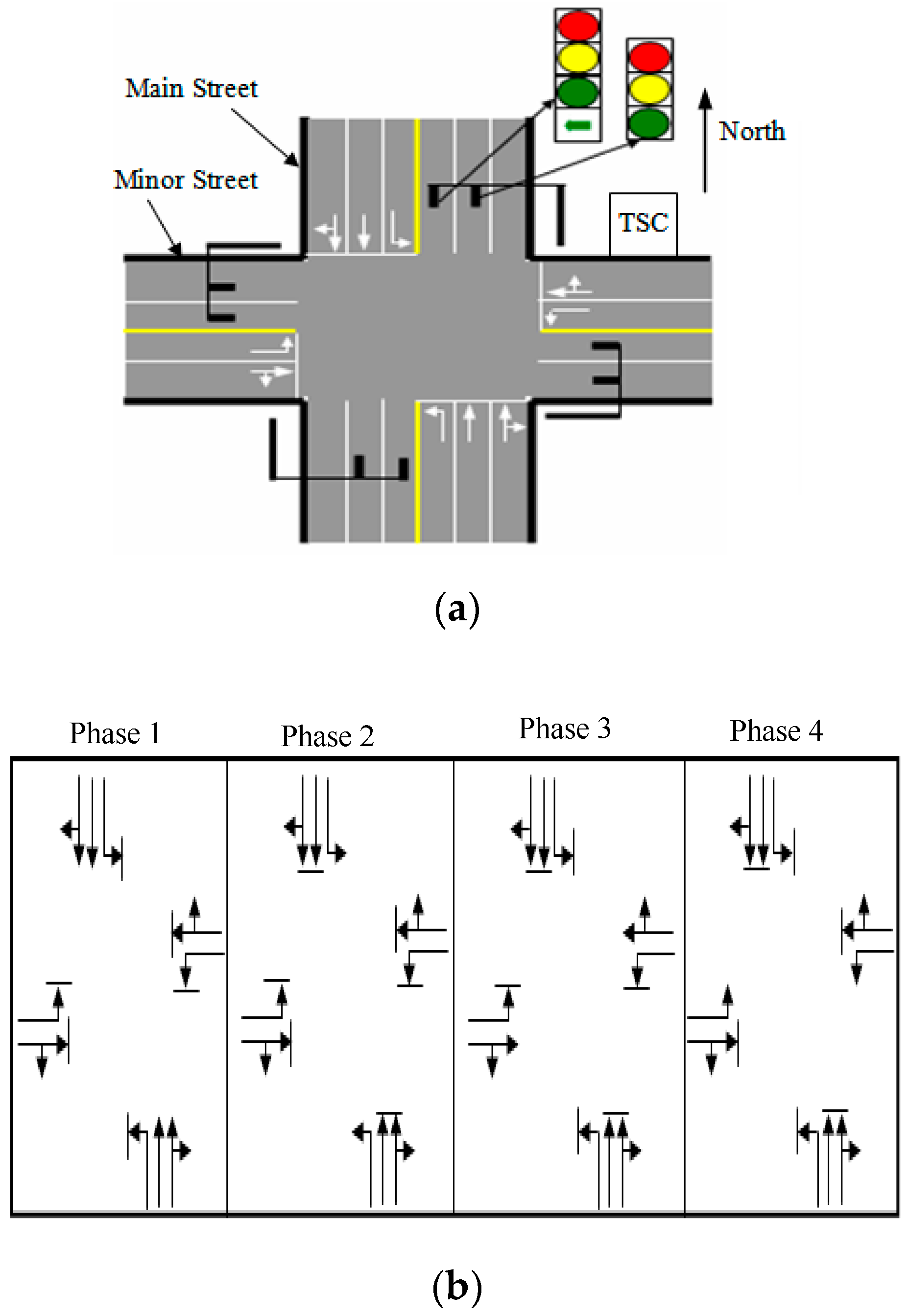
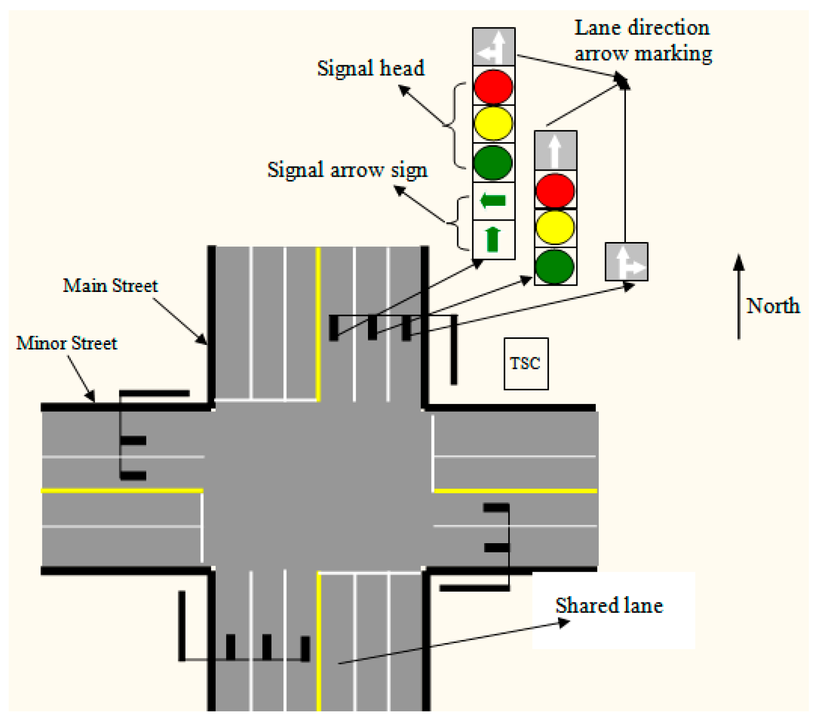
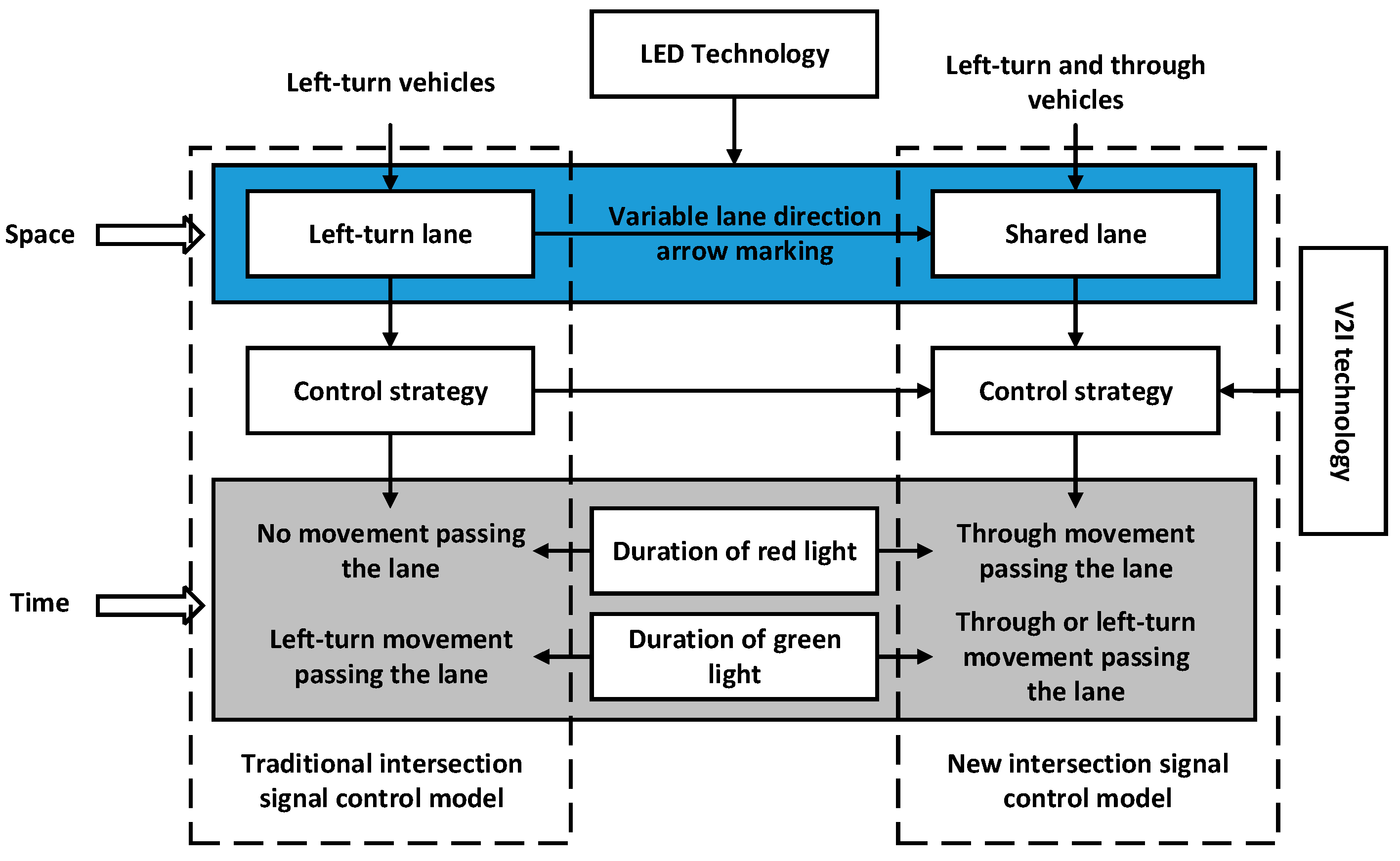
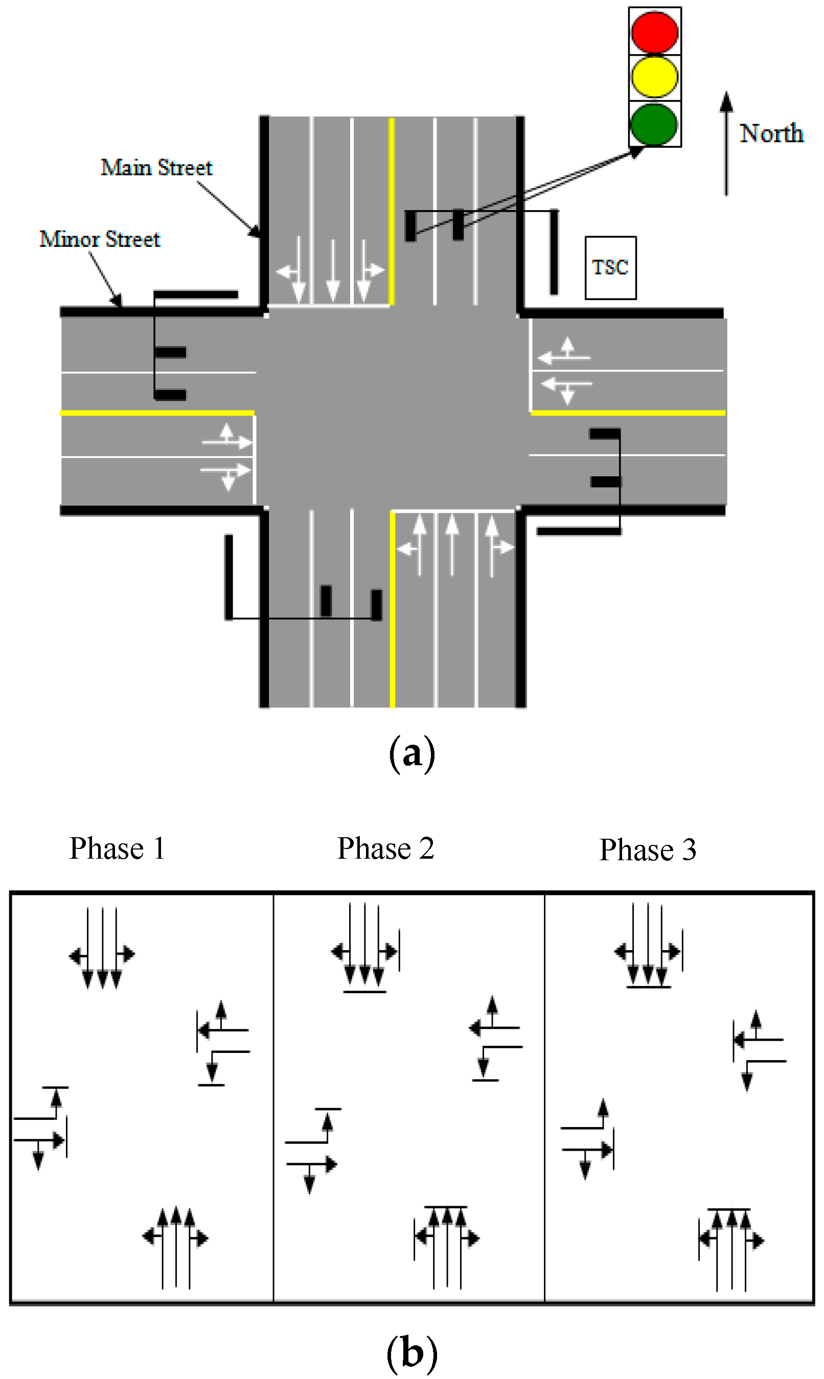
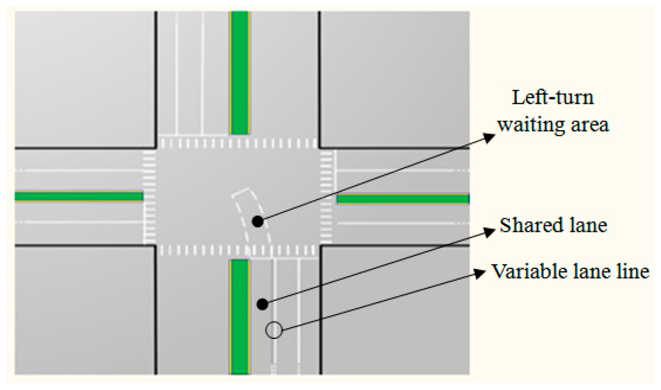
3.1. The New Intersection Signal Control Model

In order to solve the problem of lane space and phase duration waste caused by fewer or no left-turning vehicles in the left-turn lane, the exclusive left-turn lane is redesigned as a shared lane, in which the left-turning vehicles and through vehicles are permitted at the same time. The shared lane can be realized by changing the invariable lane direction arrow marking on the road surface to a variable one based on display technology (e.g., light-emitting diode, LED). Herein the intersection signal control model with the shared lane and variable lane direction arrow markings is named as the new intersection signal control model, in comparison to the traditional intersection (Figure 1a), and is shown in Figure 2.
In Figure 2, instead of painting on the lane surface, lane direction arrow markings are mounted on a post above the corresponding lane with the signal heads and signal arrow signs. The lane direction arrow markings and signal arrow signs are designed using LED lights, which can display different signs. For example, the lane direction arrow marking above the shared lane can display left-turn, through, and through and left-turn arrow signs. When the lane direction arrow marking is a through and left-turn arrow sign, the left-turn and through vehicles can use this lane at the same time, which is just the function of a shared lane. In the new intersection signal control model, the shared through–right lane direction arrow markings can also display different signs, but these markings do not change in this paper, as the shared lane for through and left-turning vehicles and its markings are our research focus.

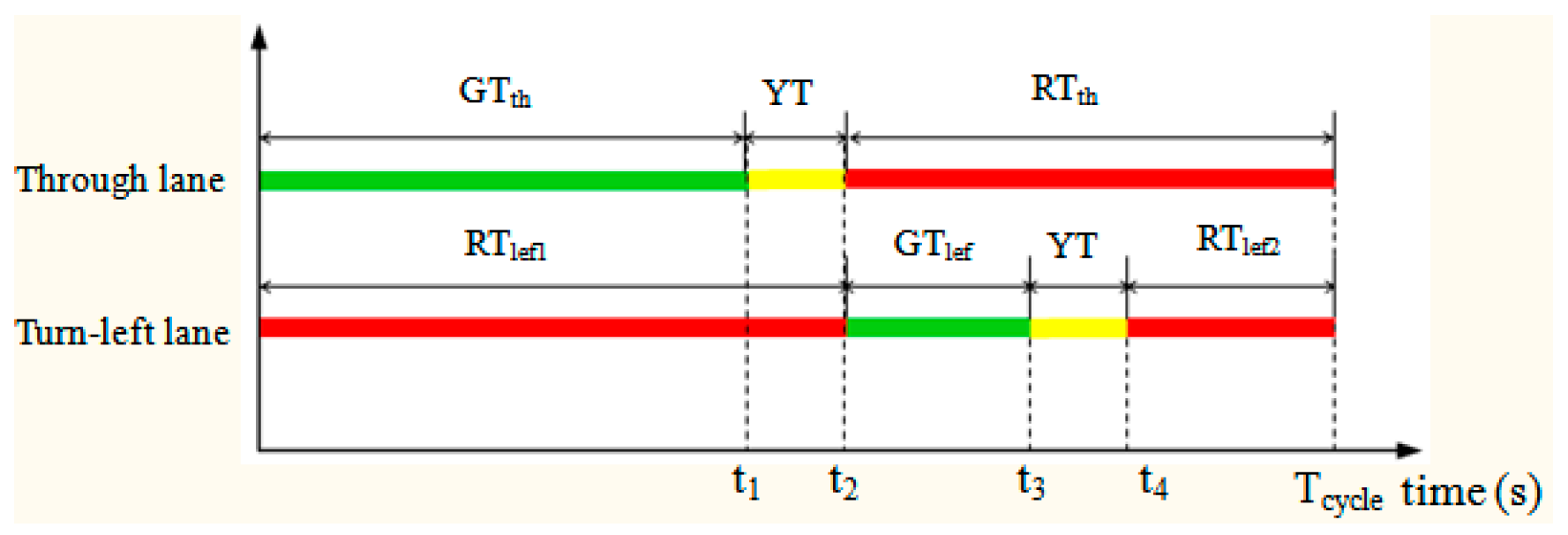
3.2. The Control Principle

In the new intersection signal control model, every vehicle has an onboard communication device, and the TSC (traffic signal controller) can communicate with them within the communication range of the V2I technology, by which the real-time vehicle movement information can be sent to the TSC. This information includes the vehicle type; the left-turn, right-turn, and through information; ID; position; and time stamp of each vehicle.
In addition, the TSC can analyze information from vehicles and decide the phase and phase duration of the next cycle based on the control strategy during the green signal time for the opposite direction. As in Figure 1, TSCs get and analyze information from vehicles during phase 3 and phase 4, and then decide the time duration of phase 1 and phase 2. In the scenario of less or no left-turn movements in the shared lane, all or some of the phase duration previously applied only for through movements can be used by the through vehicles in the shared lane. Furthermore, the part of the phase duration previously only for left-turn movements can also be used by through vehicles in the shared lane. Thus, the capacity of the intersection will be increased, and the performance of the intersection will be improved.
A diagram presenting the control principle of the new intersection signal control model and comparing it to the traditional intersection control model is shown in Figure 3.

4. The New Intersection Signal Control System and Control Strategy
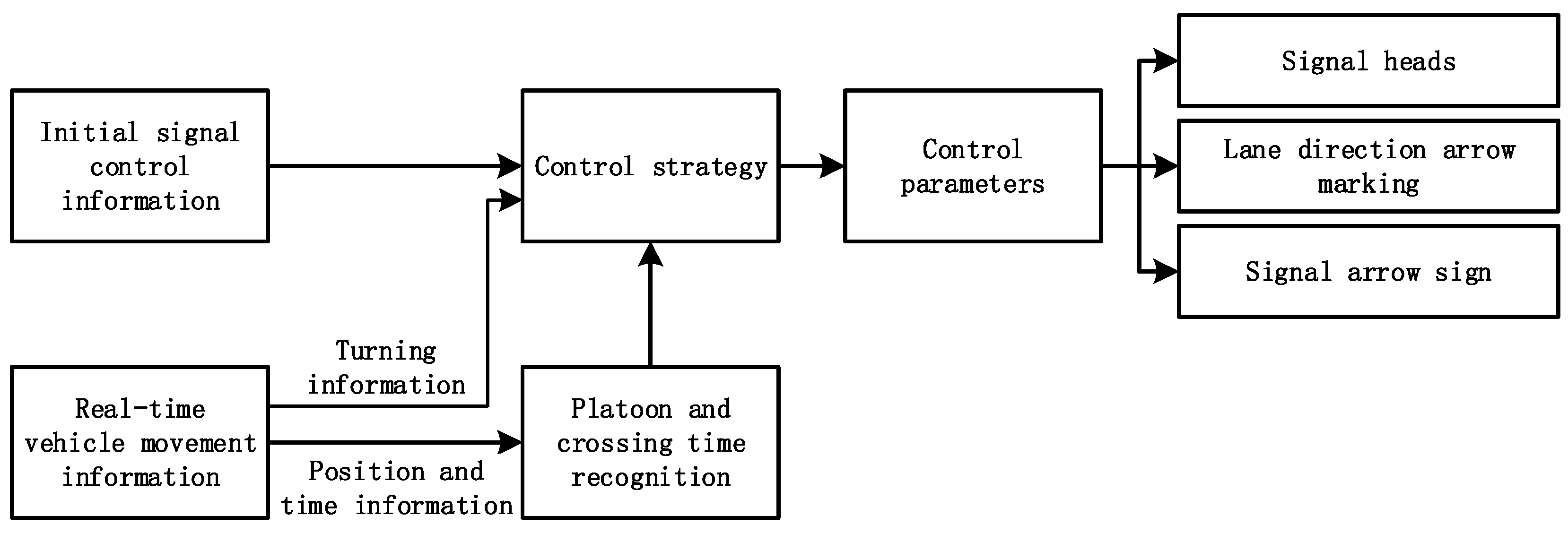
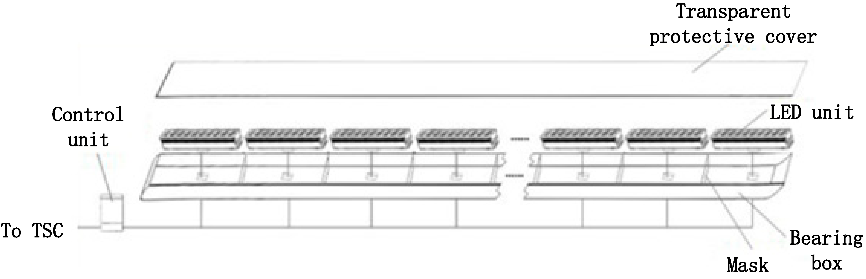
4.1. Control System

The control system block diagram for the new intersection signal control model is shown in Figure 4. The control strategy is the key part and is discussed in Section 4.2.
Based on the control principle (Figure 3), the inputs of the control system include the fixed-time signal control parameters and the real-time vehicle movement information by V2I. The fixed-time signal control parameters, which are defined as the initial signal control information, include cycle length, phase and phase duration, yellow signal duration, and all-red signal duration.
The outputs of the control system are the control parameters for signal heads, lane direction arrow markings, and signal arrow signs. The control parameters for signal heads mainly include phase and phase duration. Here the cycle length, yellow signal, and all-red signal duration are supposed the same as initial signal control information. The control parameters for lane direction arrow markings include left-turn arrow, through arrow, or left-turn and through arrow. The control parameters for signal arrow signs denote that left-turn movements or through movements are permitted to pass the intersection.

4.2. Control Algorithm

4.2.1. The Initial Signal Control Information

The initial signal control information is the fixed-time control parameters based on [63,64], which were optimized and are suitable for the traffic flow dynamics of the day at the intersection (Figure 1), as shown in Figure 5. The variables are defined as follows:
Tcycle: the signal cycle;
YT: yellow signal duration;
GTth: through phase duration;
RTth: red signal duration in the through lane;
GTlef: left-turn phase duration;
RTlef1, RTlef2: red signal duration in the left-turn lane.
In addition, some time points to be used later in this paper are shown in Figure 5, such as t1, t2, t3 and t4, which can be expressed as Equation (1).
{ t 1 = G T t h                             t 2 = t 1 + Y T               t 3 = t 2 + G T l e f         t 4 = t 3 + Y T                

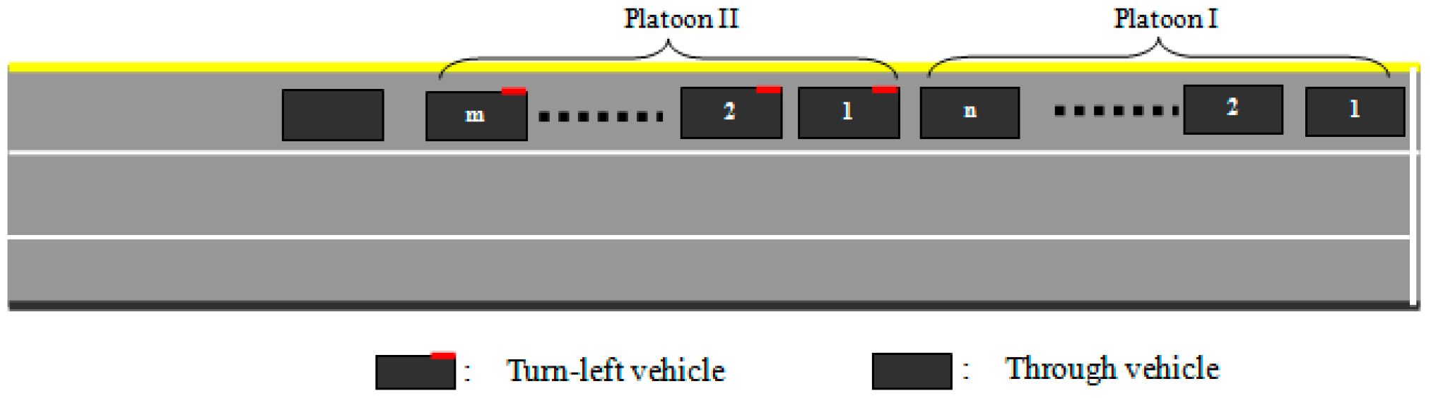
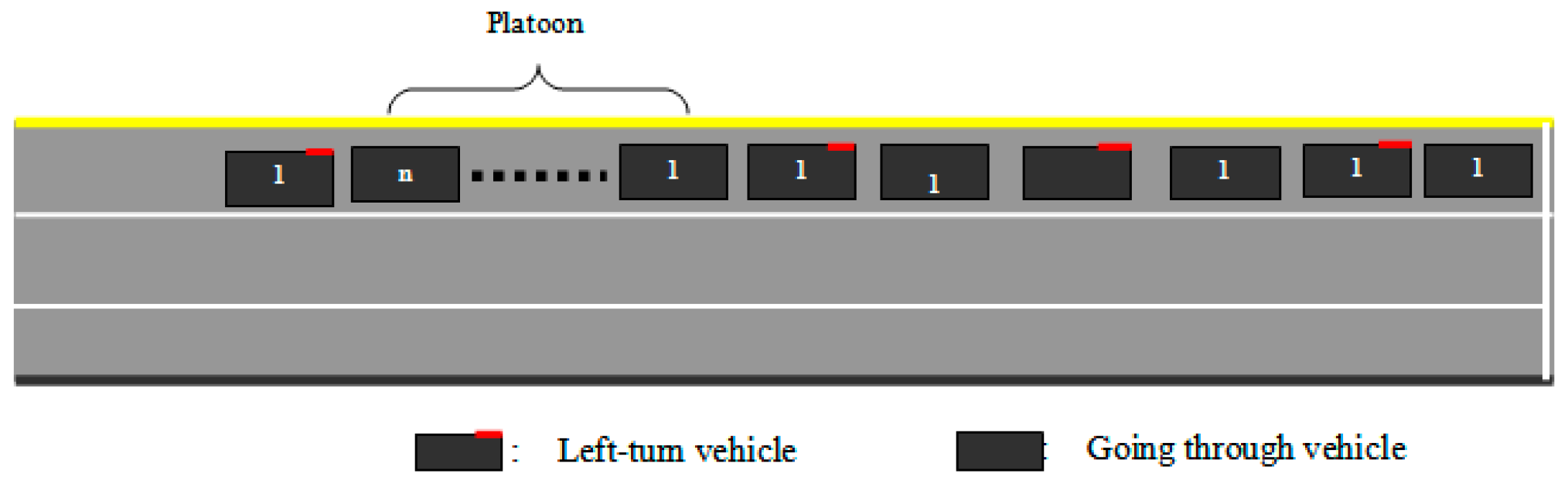
4.2.2. Platoon Recognition and Its Passing Stop-Line Time Computation

In the new intersection signal control model, the through vehicle and left-turning vehicle coexist in the shared lane. If the time where they pass the stop line is obtained, the times RTlef1, GTlef can be used sufficiently. A method is proposed to calculate the passing stop-line time of vehicles in the shared lane based on the V2I information. The method includes platoon recognition and its passing stop-line time computation.
(1) Platoon Recognition
In the shared lane, the continuous and same-turn-signal vehicles are defined as a platoon. For example, in Figure 6, platoon I (PI) from the first to the nth vehicle are all through movement, but platoon II (PII) from the first to mth vehicles are all turning left. Platoon recognition is defined as the number of vehicles in the same platoon.
From Figure 5, during the time RTlef2, vehicles will stop and queue up in the shared lane, and at the same time, the TSC will receive and analyze the real-time information from the vehicles in the shared lane. Based on the real-time information, the TSC obtains the left-turning and through vehicles’ position distribution in the shared lane, recognizes the platoon, and obtains the number of vehicles and type of each vehicle in the platoon. For example, in Figure 6, PI includes the through vehicles from the first to the nth, and PII includes left-turning vehicles from the first to the mth, and the number of the PI and PII vehicles is n and m, respectively. Note that there may be different types of vehicles in the same platoon. In this situation, the number of vehicles in platoons should be converted to the number of standard cars according to the vehicle type. PI and PII in Figure 6 are assumed to be standard cars.
(2) Time of Platoon Passing the Stop Line
The time of the platoon passing the stop line at the intersection is related to many factors, such as driver behavior, reaction to the light, the intersection’s topography, the headway of the platoon, etc. Some related research efforts have been made [65,66]. Because of the many factors related to the parameter, computation complexity is high. Besides, based on the V2I communication, a large amount of data about the time of vehicles passing the intersection is obtained easily, and one method is proposed here.
In the shared lane, once the green signal begins, the queued vehicles start and pass the intersection successively. Based on the vehicle position and time stamp, the TSC can obtain the time of vehicles passing the stop line, and then the number of vehicles passing the stop line can be computed according to the vehicle IDs. Therefore, the time of the platoon passing the stop line, in which the number of vehicles is recognized, can be calculated. Due to the differences between left-turning and through vehicles passing an intersection, the statistical data should be computed respectively.
Suppose the vehicles in the left-turn movement platoon are referred to as lef 1 , lef 2 , , lefn , the vehicles in the through movement platoon are th 1 , th 2 , , thm , and the corresponding time stamps of vehicles passing the stop line are t l e f 1 , t l e f 2 , , t l e f n t t h 1 , t t h 2 , , t t h m , respectively.
Then, the time of the platoon passing the stop line can be obtained according to the start of green:
{ T l e f =   t l e f n T 0 , T t h =   t t h m T 0 ,
where   T l e f is the time of the left-turn movement platoon passing the stop line;
T t h is the time of the through movement platoon passing the stop line; and
T 0 is the start of green.
Thus, the time of all left-turn and through movement platoons passing the stop line can be obtained. Then, according to the obtained data, the average time τ l e f N τ th N of the platoon with the same number of left-turning and through vehicles passing the stop line can be calculated :
{ τ l e f N = AVERAGE ( T l e f N 1 T l e f N 2 ) , τ th N = AVERAGE ( T t h N 1 T t h N 2 ) ,
where N is the number of vehicles in the platoon, N = 1,2,3, …;
T l e f N 1 , T l e f N 2 , are the time of the platoon with N left-turning vehicles to pass the stop line;
T t h N 1 ,   T t h N 2 , are the time of the platoon with N through vehicles to pass the stop line.
According to this, the time series { τ l e f 1 τ l e f 2 τ l e f 3 } and { τ th 1 τ th 2 τ th 3 } can be obtained. The time series is the average time of the left-turn movement platoon and through movement platoon passing the stop line under different numbers of vehicles in the shared lane at the intersection.
Then, according to the number of vehicles in the platoon recognition, the time of the platoon passing the intersection can be obtained by searching the time series. For example, if the number of vehicles in PI is N, the time T p 1 can be obtained:
T p 1 = { τ l e f N                       P I     is   the   vehicles   turning   left τ th N                             P I     is   the   through   vehicles          
Similarly, the time TP2 for PII can be obtained.

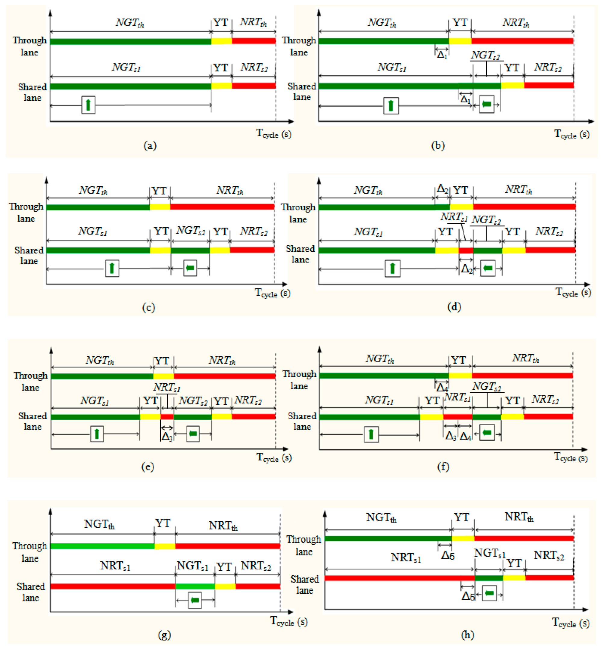
4.2.3. The Control Strategy

In the signal control system, once the control parameters are obtained, the TSC will drive the traffic light to fulfill the intersection control process. The control parameters are calculated by the control strategy, which is a key component of traffic signal control.
The inputs of the new intersection control system are initial signal control information and the real-time vehicle movement information. Based on Figure 5, the initial signal control information includes Tcycle, GTth, YT, RTth, RTlef1, GTlef, and RTlef2.
On the basis of Formula (4), the real-time information includes the Tp1 and Tp2 for PI and PII, and their left-turn or through signal information, where flag = 0 means left-turning vehicle and flag = 1 means through vehicle. The real-time information can be expressed as PI(Tp1, flag), PII(Tp2, flag).
The output control parameters for signal heads above the through lane include green signal duration and red signal duration, labeled as NGTth, NRTth, respectively, and the parameters for the shared lane include green signal duration and red signal duration. Because left-turn and through vehicles coexist in the shared lane, the green and red signal durations may be composed of one or two segments, defined as NGTs1 and NGTs2 for the green signal, and NRTs1 and NRTs2 for the red signal. Among them, red signal duration NRTs2 = RTlef2, in which the right-of-way is for opposite traffic flow, is constant.
From what has been discussed above, the control system can be expressed as the following mathematical expression:
[NGTth, NRTth, NGTs1, NGTs2, NRTs1] = f {Tcycle, GTth, RTth, RTlef1, GTlef, RTlef2, YT, PI(Tp1, flag), PII(Tp2, flag)}.
The process for the control strategy is the following.
(1) Flag = 1 in PI(Tp1, flag)
This means that PI is composed of through vehicles, and the control strategy is as follows:
A: If Tp1 ≥ t3, then
Shared lane: NGTs1 = RTlef1 + GTlef, NGTs2 = 0, NRTs1 = 0, at green time NGTs1 the signal arrow sign is for through movement.
Through lane: NGTth = RTlef1 + GTlef, NRTth = RTlef2
Regarding the output signal control parameters, the control phases can be described as (a) in Figure 7.
B: Else if t2Tp1 < t3, then
Let Δ1 = Tp1 – t2.
Shared lane: NGTs1 = RTlef1 + Δ1, NGTs2 = GTlef – Δ1, NRTs1 = 0, at the time of NGTs1 the signal arrow signs are for through movements, and the time NGTs2 is for left-turn movements.
Through lane: NGTth = GTth + Δ1, NRTth = RTth – Δ1
Regarding the output signal control parameters, the control phase can be described as (b) in Figure 7.
C: Else if t1Tp1 < t2, then
① If Tp2GTlef, then
Shared lane: NGTs1 = GTth, NGTs2 = GTlef, NRTs1 = 0, at the time of NGTs1 the signal arrow signs is for through movements, and the time NGTs2 is for left-turn movements.
Through lane: the phase durations do not change, NGTth = GTth, NRTth = RTth.
Regarding the output signal control parameters, the control phase can be described as (c) in Figure 7.
② Else (means Tp2 < GTlef) then
Let Δ2 = GTlefTp2.
Shared lane: NGTs1 = GTth, NGTs2 = GTlef – Δ2, NRTs1 = Δ2, at the time of NGTs1 the signal arrow sign is for through movements, and the time NGTs2 is for left-turn movements.
Through lane: NGTth = GTth + Δ2, NRTth = RTth – Δ2.
Regarding the output signal control parameters, the control phase can be described as (d) in Figure 7.
D: Else if 0 < Tp1 < t1, then
Let Δ3 = GTthTp1.
① If Tp2GTlef, then
Shared lane: NGTs1 = GTth – Δ3, NGTs2 = GTlef, NRTs1 = Δ3, at the time of NGTs1 the signal arrow sign is for through movements, and the time NGTs2 is for left-turn movements.
Through lane: the phases do not change, NGTth = GTth, NRTth = RTth.
Regarding the output signal control parameters, the control phase can be described as (e) in Figure 7.
② Else (means Tp2 < GTlef) then
Let Δ4 = GTlefTp2.
Shared lane: NGTs1 = GTth – Δ3, NGTs2 = GTlef – Δ4, NRTs1 = Δ3 + Δ4. At the time of NGTs1 the signal arrow sign is for through movements, and the time NGTs2 is for left-turn movements.
Through lane: NGTth = GTth + Δ4, NRTth = RTth – Δ4.
Regarding the output signal control parameters, the control phase can be described as (f) in Figure 7.
(2) Flag = 0 in the PI(Tp1, flag)
This means that PI is making left-turn movements, and the control strategy is as follows:
A: If Tp1GTlef then
Shared lane: NGTs1 = GTlef, NGTs2 = 0, NRTs1 = RTlef1, at the time of NGTs1 the signal arrow sign is for left-turn movements.
Through lane: NGTth = GTth, NRTth = RTth.
Regarding the output signal control parameters, the control phase can be described as (g) in Figure 7.
B: Else (means 0 < Tp1 < GTlef) then
Let Δ5 = GTlefTp1.
Shared lane: NGTs1 = GTlef – Δ5, NGTs2 = 0, NRTs1 = RTlef1 + Δ5, at the time of NGTs1 the signal arrow sign is for left-turn movements.
Through lane: NGTth = GTth + Δ5, NRTth = RTth – Δ5.
Regarding the output signal control parameters, the control phase can be described as (h) in Figure 7.

5. Simulation and Results
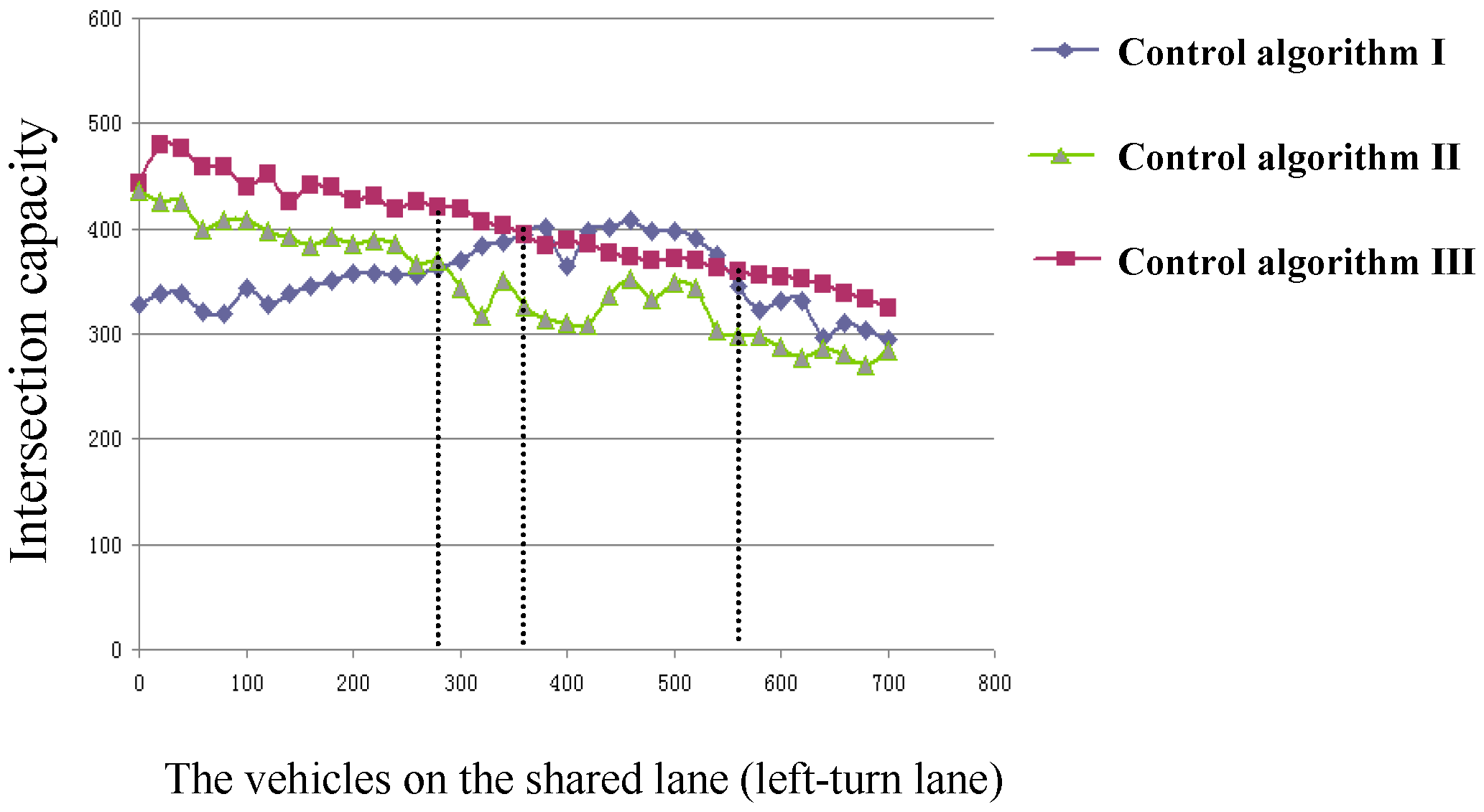
In this section, the new intersection signal control model and control strategy were evaluated based on an intersection located in Qingdao, China with a fixed-time signal control strategy. Relevant data and control parameters were obtained from the intersection. The cycle length was 129 s, the phases were the same as in Figure 1b, and the Phase 1 green signal duration was 48 s, Phase 2 was 25 s, Phase 3 was 25 s, and Phase 4 was 19 s. The intersection traffic state in rush hour was focused, in which very few vehicles were observed in the left-turn lane, a ratio of left-turning vehicles to total vehicles from 5% to 12.5% was observed, and the total vehicles were about 1800 per hour.
In this paper, VISSIM software was used as the simulation tool. The simulated intersection was designed and operated based on the data of the actual intersection. Firstly, the intersection model is shown in Figure 1a with an exclusive left-turn lane, and its control strategy was fixed-time. In the scenario, it is named as control algorithm I and the corresponding simulation process is called Simulation I.
Secondly, the lane direction arrow marking on the left-turn lane surface was painted as a through and left-turn arrow sign, as shown in Figure 8a. In this intersection model, the left-turning vehicles and through vehicles were in the same phase, so there were three phases of the intersection: Phase 1 for northbound and southbound left-turn and through movement, Phase 2 for the eastbound and westbound through movement, and Phase 3 for the eastbound and westbound left-turn movement, as shown in Figure 8b. Its control strategy was also fixed-time. The scenario is named as control algorithm II and the corresponding simulation process is called Simulation II.
Thirdly, the new intersection signal control model is shown in Figure 2 with shared lane, variable lane direction arrow markings. Its proposed control strategy is shown in Figure 7. The scenario is named as control algorithm III and the corresponding simulation process is called Simulation III.
The number of vehicles and the cycle length of the traffic control signal were the same in the three simulation processes. Because Simulation III had eight control results, the simulation time was set as 129 × 8 = 1032 s, and based on the total number of vehicles 1800 vehicle/h from the actual intersection, the numbers of left-turning vehicles of 100, 160, and 220 were selected.
In the simulation design, five signal groups in the signal controller for the intersection were considered, which had the same sequence (e.g., red–green–yellow). Signal group 1 controlled the through/right-turn vehicle movements for eastbound/westbound directions. Signal group 2 controlled the through movement for the shared lane. Signal group 3 controlled the through/right-turning vehicle movements for other directions. Signal group 4 controlled the left-turn movement for other directions. Signal group 5 controlled the turning movement for the shared lane.
In Simulation III, the shared lane was accessible to left-turning vehicles and through vehicles, the phase duration time was time-varying. To simulate the new signal control model and strategy (shown in Section 4.2.3), eight different periods were designed, which implemented different signal control strategies.
The results obtained included the number of vehicles passing the intersection (capacity of the intersection) with different input left-turning vehicles, and the percentage increase of Simulation III and II to Simulation I (Table 1). From Table 1, the capacity of the intersection increased in Simulations II and III, and Simulation III achieved the best results, meaning the proposed new signal control model and strategy could increase the performance of the intersection.
Besides, the three intersection signal control algorithms were simulated under different numbers of left-turning vehicles in the left-turn lane, and the capacities were obtained as shown in Figure 9.
From the results obtained in Figure 9, we can conclude the following:
(1)
As the vehicles on the left-turn lane increased gradually, the intersection traffic capacity decreased under control algorithms II and III and increased for a long time under control algorithm I.
(2)
When the number of vehicles in the left-turn lane was less than N1, control algorithm III was the best for intersection traffic capacity, followed by control algorithm II, and the worst was control algorithm I. This means that control algorithms II and III are suitable for fewer left-turn movements. N1 was the turning point of control algorithms I and II. Below N1, control algorithm II was better, but after N1 control algorithm I was better.
(3)
N2 and N3 were the turning points of control algorithm I and control algorithm III. Below N2, control algorithm III was better. Above N2 and below N3, control algorithm I was better than control algorithm III. After N3, the control algorithm III was the best.
(4)
The control algorithm for the intersection can be given as follows:
① If the number of left-turning vehicles is less than N2 or more than N3, control algorithm III should be selected;
② If the number of left-turning vehicles is between N2 and N3, control algorithm I should be selected;
③ Under the condition of V2I technologies not being applied to the intersection control, control algorithm II should be used to improve the intersection traffic capacity, but its suitability term is the number of left-turning vehicles less than N1.
Some discussions are as follows:
(1) In this paper, a new intersection signal control model is designed, the corresponding control strategy is proposed, and simulation showed that the new intersection signal control model and control strategy could improve the intersection capacity, especially in case of fewer left-turning vehicles in peak hours. However, other control models can be used in the case of more left-turning vehicles, as summarized in (4) above.
(2) The basic condition of the new intersection signal control model and strategy is that the left-turning and through vehicles line up in the shared lane as a platoon, but randomness is introduced when a vehicle without platoon control enters the shared lane. Due to fewer left-turning vehicles, the probability that left-turning and through vehicles will appear intermittently in a long period of time is impossible. Otherwise, it indicates that the number of left-turning and through vehicle is approximately equal, and the new intersection control model and algorithm is not suitable. However, in a short time period, it is possible that left-turning and through vehicles will appear intermittently, as shown in Figure 10.
Under this case, it will be difficult for the control method proposed in this paper to improve the traffic efficiency of intersections. To solve the problem, a left-turn waiting area and a variable lane line were set up as shown in Figure 11.
Left-turn waiting areas have been adopted in many urban intersections in China [32,33]. They are located at the front end of the left-turn lane (it is shared lane in this study) and extend into the interior of the intersection. The extension length should ensure that the left-turning vehicles waiting within this range do not conflict with the traffic flow in the opposite direction. Two parallel white dotted lines mark the left-turn waiting area, and the front end marks the stop line.
The design and working principle of the variable lane line are given in this paper. The variable lane line is composed of LED units, a transparent protective cover, a bearing box, the mask, and the control unit. The overall structure schematic diagram is shown in Figure 12.
The variable lane line LED unit groups are changeable, the number of groups in accordance with the length of the approach lane of the intersection, and connected to the TSC. The TSC can control the state of the variable line (e.g., on or off state), and its working diagram is shown in Figure 13. The variable lane line groups in Figure 13 consist of 13 LED units. Figure 13a demonstrates the working principle and effect of the variable lane line. When the LED is off, the variable lane color will be the same as the road surface (here it is shown in a different color to indicate its existence). Figure 13b represents the combination of variable lane line and conventional lane line with fixed marking, which is in a non-working state. In other words, this situation indicates that vehicles in the shared lane and its adjacent through lane cannot change lanes with each other. Figure 13c represents the combination of variable lane line and conventional lane line in a working state (i.e., through vehicles in the shared lane can change to the adjacent through lane if the through signal is allowed and lane changing is safe, but the vehicles in the through lane are prohibited from changing lanes to the shared lane).
In this circumstance, the control strategy of the shared lane will firstly give the through signal, and then the left-turn signal. As for the signal duration time for the through and left-turn movements, the storage capacity of the left-turn waiting area can be used as the basis for calculation. Assuming the time for the number of vehicles with the storage capacity to pass through the intersection is Tw, the left-turn phase duration time GTlef must be greater than Tw (i.e., GTlef > Tw), then the signal control phase diagram can be obtained under this condition, as shown in Figure 14. In the figure, Δ = GTlef – Tw, NGTth = GTth + Δ, NGTs1 = RTlef1 + Δ, NGTs2 = Tw. This control strategy is similar to the control phases (b) in Figure 7, and only the through and left-turn control durations are different (i.e., NGTth, Δ, NGTs1, and NGTs2 are different).
Under this control strategy, the shared lane is firstly given the through signal, and then left-turn signal. At the through signal time the left-turning and through vehicles will move forward in turn. The through vehicles directly pass through the intersection and the left-turning vehicles will enter the left-turn waiting area. For example, for the vehicles in the shared lane of Figure 10, the first through vehicle will leave the stop line and pass the intersection directly, the second left-turning vehicle will enter the waiting area, then the third through vehicle will pass the intersection, and then the fourth left-turning vehicle will enter the waiting area. This continues in turn until the waiting area is full of left-turning vehicles. The process of the vehicle movements diagram is shown in Figure 15a.
If there are no left-turning vehicles in the shared lane when the left-turn waiting area is full and the through green time is not ended, the through vehicles will pass through the intersection successively until the end of the through green time.
If there are still left-turning vehicles in the shared lanes, the left-turning vehicles will follow the through vehicles forward until stopping at the stop line, and this will inevitably hinder the subsequent through vehicles from passing the intersection. In this case, the variable lane line is activated (i.e., the lane line is in the working state; Figure 13c), which makes the through vehicles in the shared lane able to change lanes to the adjacent through lane, and then pass the intersection. The process of the vehicle movements diagram is shown in Figure 15b.
Moreover, when the green time for through movements is over, the green signal for left-turning movement is active, so the left-turning vehicles in the left-turn waiting area and the shared lane will pass through the intersection, while the through vehicles in the shared lane can move forward in turn to reach the stop line. The process of vehicles movements diagram is shown in Figure 15c.

6. Conclusions and Future Work

To improve the capacity of intersections with an exclusive left-turn lane in the case of fewer left-turning vehicles, especially in rush hour, a new intersection signal control model and control strategy are presented. This new intersection model includes a shared lane, realized by a variable lane direction arrow marking instead of markings painted on the surface of the road. Under the new intersection control model, a control strategy based on V2I communication technology is proposed.
To evaluate the intersection control model and strategy, an actual intersection was selected with field data collected, and micro-simulations of three different intersection control models and strategies with VISSIM software were conducted. The results show that the new intersection control model and strategy could increase the intersection capacity. The new intersection control model and strategy did not work well when the left-turning and through vehicles appeared intermittently in a short time period in the shared lane. This problem can be solved by setting up a variable lane line and left-turn waiting area at the intersection. In this circumstance, the control strategy was designed and the vehicle movements in different cases were discussed.
However, the new intersection signal control model and strategy was simulated with one-directional traffic, and the control strategy will be studied for all-direction traffic. Moreover, a strategy for the comprehensive application of variable lane direction arrow marking, variable lane lines, and shared lanes will be conducted to improve the intersection efficiency. Furthermore, some realistic constraints, such as the start time of the green phases, will be considered for further study.

Author Contributions

Methodology, C.R. and J.W.; Supervision, C.R. and Y.C.; Writing—original draft, J.W., L.Q. and S.L.; Writing—review and editing, C.R., and Y.C.

Funding

This research was funded by National Natural Science Foundation of China under grant number 71801144, Key Research and Department project of Shandong Province under grant number 2019GGX101008 and China Postdoctoral Science Foundation Funded Project under grant number 2019M652437.

Acknowledgments

Thanks to the editors and reviewers for their careful review, constructive suggestion and reminding, which helped improve the quality of the paper.

Conflicts of Interest

The authors declare no conflict of interest.

References

  1. Desta, R.; Teklu, B.; Dananto, M. Simulation experiments and validation for considering bus priority treatments in small cites: The case of Hawassa city, Ethiopia. Int. J. Eng. Sci. Technol. 2018, 10, 21–28. [Google Scholar] [CrossRef] [Green Version]
  2. Zhang, T.; Mao, B.; Chen, Z.; Ma, C.; Li, J. Research on bus signal priority strategy for urban arteries based on real-time vehicle queuing detection. In Proceedings of the IEEE 4th International Conference on Cloud Computing and Big Data Analysis, Chengdu, China, 12–15 April 2019. [Google Scholar]
  3. Zhang, S.J.; Jia, S.P.; Bai, Y.; Mao, B.H.; Ma, C.R.; Zhang, T. Optimal adjustment schemes on the long through-Type bus lines considering the urban rail transit network. Discret. Dyn. Nat. Soc. 2018. [Google Scholar] [CrossRef]
  4. Hai, Y.; Tang, Y. Managing rail transit peak-Hour congestion with a fare-reward scheme. Transp. Res. Part B 2018, 110, 122–136. [Google Scholar]
  5. Gao, G.; Sun, H.; Wu, J. Activity-Based trip chaining behavior analysis in the network under the parking fee scheme. Transportation 2019, 46, 647–669. [Google Scholar] [CrossRef]
  6. Gao, G.; Sun, H.; Wu, J.; Liu, X.; Chen, W. Park-and-Ride service design under a price-Based tradable credits scheme in a linear monocentric city. Transp. Policy 2018, 68, 1–12. [Google Scholar] [CrossRef]
  7. Sumalee, A.; Ho, H.W. Smarter and more connected: Future intelligent transportation system. IATSS Res. 2018, 42, 67–71. [Google Scholar] [CrossRef]
  8. Cunha, F.; Maia, G.; Ramos, H.S.; Perreira, B.; Celes, C.; Campolina, A.; Rettore, P.; Guidoni, D.; Sumika, F.; Villas, L.; et al. Vehicular networks to intelligent transportation systems. Emerg. Wirel. Commun. Netw. Technol. 2018, 297–315. [Google Scholar] [CrossRef]
  9. Newell, G.F. Theory of highway traffic signals. Res. Rep. Inst. Transp. Available online: https://escholarship.org/uc/item/7zn2b9bc (accessed on 27 July 2017).
  10. Hummer, J.E. Unconventional left-Turn alternatives for urban and suburban arterials—Part one. ITE J. 1998, 68, 26–29. [Google Scholar]
  11. Hummer, J.E. Unconventional left-Turn alternative for urban and suburban arterials—Part two. ITE J. 1998, 68, 101–106. [Google Scholar]
  12. Bared, J.G.; Kaisar, E.I. Benefits of split intersections. Transp. Res. Rec. J. 2000, 1737, 34–41. [Google Scholar] [CrossRef]
  13. Tabernero, V.; Sayed, T.; Koscica, D. Introduction and analysis of new unconventional intersection scheme: Upstream signalized crossover intersection. In Proceedings of the 84th Annual Meeting of the Transportation Research Board, Washington, DC, USA, 9–13 January 2005. [Google Scholar]
  14. Tabernero, V.; Sayed, T. Upstream signalized crossover intersection: An unconventional intersection scheme. J. Transp. Eng. 2006, 132, 907–911. [Google Scholar] [CrossRef]
  15. Parsons, G.F. The parallel flow intersection: A new two-Phase signal alternative. ITE J. 2007, 77, 28–37. [Google Scholar]
  16. Rodegerdts, L.A.; Nevers, B.L.; Robinson, B. Signalized intersections: Informational Guide; FHWA-HRT-04-091; Federal Highway Administration: Washington, DC, USA, 2004.
  17. Hughes, W.; Jagannathan, R.; Sengupta, D.; Hummer, J. Alternative Intersections/Interchanges: Informational Report (AIIR); FHWA-HRT-09-060; Federal Highway Administration: Washington, DC, USA, 2010.
  18. El Esawey, M.; Sayed, T. Analysis of unconventional arterial intersection designs (UAIDs): State-of-the-Art methodologies and future research directions. Transportmetrica 2013, 9, 860–895. [Google Scholar] [CrossRef]
  19. ATTAP, University of Maryland, Unconventional Intersection Design & Strategies. Available online: http://attap.umd.edu/uaid.php (accessed on 18 September 2018).
  20. Bared, J.G.; Kaisar, E.I. Median U-Turn design as an alternative treatment for left turns at signalized intersections. ITE J. 2002, 72, 50–54. [Google Scholar]
  21. Leng, J.; Zhang, Y.; Sun, M. VISSIM-Based simulation approach to evaluation of design and operational performance of U-Turn at intersection in China. In Proceedings of the 2008 International Workshop on Modelling, Simulation and Optimization, Hong Kong, China, 27–28 December 2008. [Google Scholar]
  22. Liu, P.; Qu, X.; Wang, W.; Cao, B. Using VISSIM to model capacity of U-Turns at unsignalized intersections with non-traversable median cross sections. In Proceedings of the Transportation Research Board 89th Annual Meeting, Washington DC, USA, 10–14 January 2010. [Google Scholar]
  23. Dhatrak, A.; Edara, P.; Bared, J.G. Performance analysis of parallel flow intersection and displaced left-Turn intersection designs. Transp. Res. Rec. 2010, 2171, 33–43. [Google Scholar] [CrossRef]
  24. Elazzony, T.; Talaat, H.; Mosa, A. Microsimulation approach to evaluate the use of restricted lefts/through U-Turns at major intersections—A Case study of cairo-Egypt urban corridor. In Proceedings of the 13th International IEEE Annual Conference on Intelligent Transportation Systems, Madeira Island, Portugal, 19–22 September 2010. [Google Scholar]
  25. Xuan, Y.; Daganzo, C.F.; Cassidy, M.J. Increasing the capacity of signalized intersections with separate left turn phases. Transp. Res. Part B 2011, 45, 769–781. [Google Scholar] [CrossRef]
  26. Zhao, J.; Ma, W.; Zhang, H.; Yang, X. Increasing the capacity of signalized intersections with dynamic use of exit lanes for left-Turn traffic. Transp. Res. Rec. 2013, 2355, 49–59. [Google Scholar] [CrossRef]
  27. Suh, W.; Hunter, M.P. Signal design for displaced left-turn intersection using Monte Carlo method. KSCE J. Civ. Eng. 2014, 18, 1140–1149. [Google Scholar] [CrossRef]
  28. Zhao, J.; Ma, W.; Head, K.L.; Yang, X. Optimal operation of displaced left-Turn intersections: A lane-Based approach. Transp. Res. Part C 2015, 61, 29–48. [Google Scholar] [CrossRef]
  29. Wu, J.; Liu, P.; Tian, Z.Z.; Xu, C. Operational analysis of the contraflow left-Turn lane design at signalized intersections in China. Transp. Res. Part C 2016, 69, 228–241. [Google Scholar] [CrossRef]
  30. Xiang, Y.; Li, Z.; Wang, W.; Chen, J.; Wang, H.; Li, Y. Evaluating the operational features of an unconventional dual-Bay U-Turn design for intersections. PLoS ONE 2016, 11, e0158914. [Google Scholar] [CrossRef] [PubMed]
  31. Taha, M.M.A.; Abdelfatah, A. Impact of using indirect left-Turns on signalized intersections’ performance. Can. J. Civ. Eng. 2015, 44, 462–471. [Google Scholar] [CrossRef]
  32. Yang, Z.; Liu, P.; Chen, Y.; Yu, H. Can left-Turn waiting areas improve the capacity of left-Turn lanes at signalized intersections. Procedia-Soc. Behav. Sci. 2012, 43, 192–200. [Google Scholar] [CrossRef]
  33. Ma, W.; Liu, Y.; Zhao, J.; Wu, N. Increasing the capacity of signalized intersections with left-Turn waiting areas. Transp. Res. Part A 2017, 105, 181–196. [Google Scholar] [CrossRef]
  34. Research and Innovative Technology Administration. Available online: http://www.its.dot.gov/connected_vehicle.htm (accessed on 6 September 2013).
  35. USDOT. Connected Vehicle Reference Implementation Architecture. Available online: http://www.iteris.com/cvria/html/applications/ applications.html (accessed on 27 July 2015).
  36. USDOT. ITS Research Fact Sheets. Available online: http://www.its.dot.gov/communications/its_factsheets.htm (accessed on 27 June 2016).
  37. Jin, N. Design of visual feature detection system for intelligent driving of electric vehicle. In Proceedings of the IEEE International Conference on Robots & Intelligent System, Changsha, China, 26–27 May 2018. [Google Scholar]
  38. Yu, L.; Shao, X.; Wei, Y.; Zhou, K. Intelligent land-Vehicle model transfer trajectory planning method based on deep reinforcement learning. Sensors 2018, 18, 2905. [Google Scholar]
  39. El Hajjaji, A.; Chadli, M.; Oudghiri, M.; Pagès, O. Observer-Based robust fuzzy control for vehicle lateral dynamics. In Proceedings of the American Control Conference, Minneapolis, MN, USA, 14–16 July 2006. [Google Scholar]
  40. Mi, T.; Li, C.; Hu, C.; Wang, J.; Chen, N.; Wang, R. Robust H∞ output-Feedback yaw control for in-Wheel motor driven electric vehicles with differential steering. Neurocomputing 2016, 173, 676–684. [Google Scholar]
  41. Dahmani, H.; Chadli, M.; Rabhi, A.; El Hajjaji, A. Vehicle dynamics and road curvature estimation for lane departure warning system using robust fuzzy observers: Experimental validation. Veh. Syst. Dyn. 2015, 53, 1135–1149. [Google Scholar] [CrossRef]
  42. Milz, S.; Arbeiter, G.; Witt, C.; Abdallah, B.; Yogamani, S. Visual SLAM for automated driving: Exploring the applications of deep learning. In Proceedings of the IEEE Conference on Computer Vision and Pattern Recognition Workshops, Salt Lake City, UT, USA, 18–22 June 2018. [Google Scholar] [CrossRef]
  43. Hubmann, C.; Schulz, J.; Becker, M.; Althoff, D.; Stiller, C. Automated driving in uncertain environments: Planning with interaction and uncertain maneuver prediction. IEEE Trans. Intell. Veh. 2018, 3, 5–17. [Google Scholar] [CrossRef]
  44. Gradinescu, V.; Gorgorin, C.; Diaconescu, R.; Cristea, V.; Iftode, L. Adaptive traffic lights using car-to-Car communication. In Proceedings of the IEEE 65th Vehicular Technology Conference, Dublin, Ireland, 22–25 April 2007. [Google Scholar]
  45. Priemer, C.; Friedrich, B. A decentralized adaptive traffic signal control using V2I communication data. In Proceedings of the 12th International IEEE Conference on Intelligent Transportation Systems, St. Louis, MO, USA, 4–7 October 2009. [Google Scholar]
  46. Guler, S.I.; Menendez, M.; Meier, L. Using connected vehicle technology to improve the efficiency of intersections. Transp. Res. Part C 2014, 46, 121–131. [Google Scholar] [CrossRef]
  47. Feng, Y.; Head, K.L.; Khoshmagham, S.; Zamanipour, M. A real-Time adaptive signal control in a connected vehicle environment. Transp. Res. Part C 2015, 55, 460–473. [Google Scholar] [CrossRef]
  48. Zheng, J.; Liu, H.X. Estimating traffic volumes for signalized intersections using connected vehicle data. Transp. Res. Part C 2017, 79, 347–362. [Google Scholar] [CrossRef] [Green Version]
  49. Jiang, H.; Hu, J.; An, S.; Wang, M.; Park, B.B. Eco approaching at an isolated signalized intersection under partially connected and automated vehicles environment. Transp. Res. Part C 2017, 79, 290–307. [Google Scholar] [CrossRef]
  50. He, Q.; Head, K.L.; Ding, J. PAMSCOD: Platoon-Based arterial multi-Modal signal control with online data. Transp. Res. Part C 2012, 20, 164–184. [Google Scholar] [CrossRef]
  51. Feng, Y.; Yu, C.; Liu, H.X. Spatiotemporal intersection control in a connected and automated vehicle environment. Transp. Res. Part C 2018, 89, 364–383. [Google Scholar] [CrossRef]
  52. Ma, C.; Hao, W.; Wang, A.; Zhao, H. Developing a coordinated signal control system for urban ring road under the vehicle-Infrastructure connected environment. IEEE Access 2018, 6, 52471–52478. [Google Scholar] [CrossRef]
  53. Han, E.; Pil Lee, H.; Park, S.; So, J.; Yun, I. Optimal signal control algorithm for signalized intersections under a V2I communication environment. J. Adv. Transp. 2019. [Google Scholar] [CrossRef]
  54. Kamal, K.; Chandan, K. A real-Time traffic signal control strategy under partially connected vehicle environment. Promet Traffic Transp. 2019, 31, 61–73. [Google Scholar]
  55. Xu, Y.; Li, D.; Xi, Y.; Lin, S. Game-Based traffic signal control with adaptive routing via V2I. In Proceedings of the IEEE International Conference on Intelligent Transportation Systems, Maui, HI, USA, 4–7 November 2018. [Google Scholar]
  56. Christian, P.; Bernhard, F. A method for tailback approximation via C2I-Data based on partial penetration. In Proceedings of the 15th World Congress on Intelligent Transport Systems and ITS America's 2008 Annual Meeting, New York, NY, USA, 16–20 November 2008. [Google Scholar]
  57. Xu, B.; Jeff, B.X.; Yougang, B.; Wan, L.; Wang, J.; Eben, LS.; Li, K. Cooperative method of traffic signal optimization and speed control of connected vehicles at isolated intersections. IEEE Trans. Intell. Transp. Syst. 2019, 20, 1390–1403. [Google Scholar] [CrossRef]
  58. Li, Z.; Elefteriadou, L.; Ranka, S. Signal control optimization for automated vehicles at isolated signalized intersections. Transp. Res. Part C 2014, 49, 1–18. [Google Scholar] [CrossRef]
  59. Pereira, A.M. Traffic signal control for connected and non-Connected vehicles. In Proceedings of the Smart City Symposium Prague, Prague, Czech Republic, 24–25 May 2018. [Google Scholar]
  60. Yang, K.; Guler, S.I.; Menendez, M. Isolated intersection control for various levels of vehicle technology: Conventional, connected, and automated vehicles. Transp. Res. Part C 2016, 72, 109–129. [Google Scholar] [CrossRef]
  61. Sun, W.; Zheng, J.; Liu, H.X. A capacity maximization scheme for intersection management with automated vehicles. Transp. Res. Procedia 2018, 23, 121–136. [Google Scholar] [CrossRef]
  62. Page, T.R.D. Multiple Sources of Safety Information from V2V and V2I: Redundancy, Decision Making, and Trust-Safety Message Design Report; U.S. Department of Transportation: Washington, DC, USA, 2015.
  63. Webster, F.V. Traffic signal settings. In Road Research Technique Paper; Road Research Laboratory: London, UK, 1958. [Google Scholar]
  64. Khisty, C.J.; Lall, B.K. Transportation Engineering: An Introduction, 3rd ed.; Pearson: London, UK, 2002. [Google Scholar]
  65. Gartner, N.H. Development and implementation of an adaptive control strategy in a traffic signal network: The virtual-fixed-cycle approach. In Transportation and Traffic Theory in the 21st Century, Proceedings of the 15th International Symposium on Transportation and Traffic Theory, Adelaide, Australia, 16–18 July 2002; Emerald Group Publishing Limited: Bingley, UK, 2002. [Google Scholar]
  66. Akcelik, R.; Besley, M.; Roper, R. Fundamental Relationships for Traffic Flows at Signalized Intersections; ARRB Transportation Research Ltd.: Vermont South, VIC, Australia, 1999. [Google Scholar]
Figure 1. Traditional four-leg at-grade intersection model and its signal phase diagram: (a) Four-leg at-grade intersection model. (b) Intersection signal control phases. TSC: traffic signal controller.
Electronics 08 01058 g001
Figure 2. The new intersection signal control model diagram.
Electronics 08 01058 g002
Figure 3. The control principle diagram. LED: light-emitting diode; V2I: vehicle-to-infrastructure.
Electronics 08 01058 g003
Figure 4. Block diagram of the control system.
Electronics 08 01058 g004
Figure 5. The northbound signal phases.
Electronics 08 01058 g005
Figure 6. Platoons on the shared lane.
Electronics 08 01058 g006
Figure 7. The output control phases under different conditions: (a) Flag = 1 and Tp1 ≥ t3; (b) Flag = 1 in PI (Tp1, flag) and t2Tp1 < t3; (c) Flag = 1 and t1Tp1 < t2 and Tp2GTlef; (d) Flag = 1 and t1Tp1 < t2 and Tp2 < GTlef; (e) Flag = 1 and 0 < Tp1 < t1 and Tp2GTlef; (f) Flag = 1 and 0 < Tp1 < t1 and Tp2 < GTlef; (g) Flag = 0 and Tp1GTlef; (h) Flag = 0 and 0 < Tp1 < GTlef.
Electronics 08 01058 g007
Figure 8. Control algorithm II intersection control model and its phases diagram: (a) Intersection control model. (b) Intersection signal control diagram.
Electronics 08 01058 g008
Figure 9. The capacities of intersection under three control algorithms.
Electronics 08 01058 g009
Figure 10. The through and left-turning vehicles appearing intermittently in the shared lane.
Electronics 08 01058 g010
Figure 11. Diagram of left-turn waiting area and variable lane line for the case shown in Figure 10.
Electronics 08 01058 g011
Figure 12. Schematic diagram of variable lane line structure.
Electronics 08 01058 g012
Figure 13. Schematic diagram of variable lane line: (a) Working principle and the effect of the variable lane line; (b) Non-working state of the combination of variable lane line and conventional lane line; (c) Working state of combination of variable lane line and conventional lane line.
Electronics 08 01058 g013
Figure 14. The control phases for the case shown in Figure 10.
Electronics 08 01058 g014
Figure 15. Vehicle movements diagram in shared lane and adjacent lane: (a) Unsaturated vehicle movements with the left-turn waiting area; (b) Filled vehicle movements with the left-turn waiting area; (c) Vehicle movements in left-turn green signal.
Electronics 08 01058 g015
Table 1. The simulation results.
Input Left-Turn VehiclesCapacity of the IntersectionIncreased Percentage
Simulation I100343-
160345-
220358-
Simulation II10040919.2%
16038311%
2203898.7%
Simulation III10044028.3%
16044228.1%
22043020.1%

