Abstract
Impedance mismatch that degrades signal power transfer and affects communication reliability is a major obstacle for power line communications (PLC). Impedance matching techniques can be designed to effectively compensate for the impedance mismatch between PLC modems and power line networks at a specific frequency or for a given frequency band. In this paper, we discuss the tradeoffs that need to be made when designing an effective impedance matching network. We also make a comprehensive review of previous state-of-the-art PLC impedance matching techniques and provide a useful classification of each technique. Finally, we discuss important issues (concerns) and provide suggestions for research directions deserving more attention. This review provides a useful guideline for researchers and manufacturers to quickly understand impedance matching principles and facilitate the design of an effective impedance matching coupler for PLC applications.
1. Introduction
Power line communication (PLC [1]) technology uses existing power cables as the transmission medium for data transmission and information exchange. Due to the advantages of free extra cabling, PLC technology is considered to be one of the most economical data communication solutions. The first development of PLC technology dates back to 1918, where carrier telephony over power lines was first tested and commercially operated [2]. Since the early 1920s to the 1930s, utility corporations around the world have successfully used this technology to achieve low-speed telephone communications over high-tension power cables for control and telemetry purposes.
Due to the harsh channel environment, preliminary research activities on PLC have not attracted researchers. Since the 1990s, with the introduction of broadband PLC and the smart grid concept, PLC technology has moved from a little-known technology from the 1930s to a competitive modern technology [3]. In the past decade, PLC technology has been widely adopted by intelligent detection systems [4], automatic meter reading units [5] and smart home [6] solutions at the heart of the smart grid concept.
PLC technology can be classified into two classes: PLC over AC (Alternating Current) lines and PLC over DC (Direct Current) lines. In the past decade, PLC technology has been widely investigated and applied to smart meter and grid applications. Modern power grids are comprised of new alternative energy sources [7], which include solar and wind power as well as new types of electric appliances. Recently, the number of electronic devices connected to DC power supplies has significantly increased. PLC technology has proven to be a cost-optimized solution in intelligent detection for large deployments of electronic devices, e.g., PV (Photovoltaic) detection [8,9]. However, the inverters used to convert the generated DC power into an AC power, and fed to the grid, is a switching component, whose switching frequency and voltage harmonics lie in the PLC frequency band, which will interfere with the PLC communication signals [10] and, in some cases, the communications are completely lost. Due to the presence of the harmonic component, the filter should be designed carefully to restrain the harmonic distortion and the interference on the PLC signal. In Ref. [10], to ensure a spectral gap between the PLC carrier frequency and the switching frequency of the inverter, 132.5 kHz is selected as the carrier frequency for the designed coupling interface. Furthermore, an output filter with a low-pass stage was designed for rejecting higher-order harmonic components. In Ref. [11], the authors note that the switching noise of the DC/AC converter occupies the frequencies ranging from 5–50 kHz, which should be reduced by a high-pass filter. In Ref. [12], a PWM-VSI (Pulse-Width Modulator Voltage-Source Inverter) and an RC (Resistor Capacitor) filter were used to enhance the precision of the frequency and eliminate the harmonic components of the inverter. Furthermore, for other DC power supply applications, e.g., electric vehicles [13,14], ships [15,16], airplanes [17], wearable devices [18], and LED lighting [19,20], DC-PLC technology can reduce weight, installation costs and wiring complexity of the wiring harnesses. Therefore, designing a low-cost and compact impedance matching circuit is of the utmost importance.
PLC couplers are interface circuits [21] deployed between PLC modems (transmitter/receiver) and power line networks, where coupled/decoupled high-frequency carrier signals travel into/from electric power cables. The power waveforms could be direct current (DC) or alternating current (AC) signals, whose voltage levels [1,22] include low-voltage (<1 kV), medium-voltage (1~100 kV) and high-voltage (>100 kV) that are directly destructive to PLC devices and modems. To prevent power waveforms from damaging communication devices or modems, PLC couplers should possess the coupling function to filter the power waveform (AC or DC main voltage).
Furthermore, power cables were originally designed to transmit electric energy at 50 or 60 Hz, so they are not an ideal channel for transmitting higher frequency carrier signals [23,24,25,26]. The power line channel has additive non-white noise and has an extremely harsh environment for data communication [27,28], which results in large signal attenuation at the frequencies of interest [22]. The electronic appliances connected to the power line network are turned on and off, leading to a non-periodic impulse noise environment with a very high probability of occurrence [29], e.g., for a vehicular power line network, an engine or a set of lamps where the source of the impulse noise is caused by on/off switching. Therefore, each status change will cause a sequence of impulse noises. The various impulse noises in the power networks result in frequency selectivity of the transmission channel. Since supply current, communication signals and noise exist in the same power line channel, high-order harmonics or pulse jamming, caused by non-linear electric devices, interfere with the quality and reliability of PLC [30]. Achieving reliable communication over highly frequency-selective channels is an important issue.
Moreover, to reduce losses associated with energy delivery, power cables were made with low impedance (sometime as low as a few ohms [31]). Therefore, a mismatch often occurs between the modems and power line channels. Furthermore, for an in-home PLC, electronic devices connected to a power line network are removed randomly, leading to location- and time-variant network access impedances [23,32,33,34,35,36]. Therefore, there is a general impedance mismatch between PLC modems and power line networks, which instigates signal reflection, degrades signal power transfer and affects communication reliability. On the other hand, PLC couplers should possess impedance matching capabilities to achieve impedance matching between PLC modems and power line networks. Therefore, effective PLC coupler (interface circuit) design is a challenging goal.
PLC couplers usually include a coupling circuit and an impedance matching circuit. The coupling circuit, e.g., coupling capacitor along with the secondary winding of a transformer, is usually designed as a BPF (Band Pass Filter) circuit, to allow as much of the communication signal through as possible, while filtering out the AC or DC voltages. However, the characteristic impedance of the designed BPF circuit may not match PLC modems or power line channels, which results in ineffective couplers that require an impedance matching circuit. The impedance matching circuit was designed to effectively compensate for an impedance mismatch between the PLC modems and power line networks to maximize signal power transfer.
Reviewing previous literature on channel measurements and characterizations [23,24,25,36,37,38,39,40], some challenges, e.g., impulse noise, frequency selective channels, random loads and fluctuating access impedance, need to be overcome to ensure an effective and reliable communication over power line channels. The impedance mismatch originates from random loads and fluctuating access impedance, which results in signal reflection, degrades the signal power transfer, and affects the communication reliability. Thus, impedance matching is very important to a PLC system, which motivate this review.
The remainder of this paper is organized as follows. Section 2 summarizes the important tradeoffs that need to be considered before designing an effective impedance matching network. Section 3 provides a classification of the impedance matching approaches in PLC. Section 4 delineates open problems and future research directions. Section 5 provides a summary of the work.
2. The Tradeoffs Considered Before Designing an Effective Impedance Matching Network
In PLC systems, impedance matching is typically achieved via an impedance matching network (circuit). A PLC coupler usually includes a coupling circuit and an impedance matching circuit, which is designed to achieve impedance matching between PLC modems and power line channels. With this in mind, several issues should be considered when designing an impedance matching circuit, e.g., gain and insertion loss, efficiency and cost, bandwidth and attenuation, and matching region and structure.
2.1. The Tradeoff Between Gain and Insertion Loss
An impedance matching network is typically composed of passive elements and is designed to maximize a signal’s power transfer. For a lossless matching network, maximizing the power delivered to the receiver is equivalent to minimizing the power reflection of the matching network. The VSWR (Voltage Standing Wave Ratio) at the input port of the impedance matching network can be expressed by [41]
where is the input reflection coefficient of the two-port network. Impedance matching can be achieved by minimizing the magnitude of the reflection coefficient. In other words, a perfect match can be achieved when the (VSWR = 1).
However, in practice, any matching network composed of passive elements is lossy. Thus, the impedance matching process should be based on maximizing the power delivered to the receiver rather than minimizing the power reflection [42]. One of the main objectives of the PLC coupler is to enhance the power transfer under impedance mismatch conditions. However, the gain obtained from the impedance matching network is partially undone by insertion losses of the impedance matching network.
Insertion loss of an impedance matching network can be characterized by [43]
where is the power delivered to the load and is the power delivered to the matching network. and are the scattering parameters of the matching network (the two-port network). is the input reflection coefficient, while is the load reflection coefficient.
For a 50 source, the output power gain can be defined as the reduction in reflection loss minus the insertion loss (IL), which is inherently introduced by an impedance matching network and can be expressed as [44]
where is the input reflection coefficient of a two-port network (looking from the source into the matching network). is the load reflection coefficient.
The gain is affected by the inherent insertion loss of the passive elements in the impedance matching network. Therefore, to maximize the gain obtained by the impedance matching network, the insertion loss should be kept small. To minimize the insertion loss of the impedance matching network, the susceptance of the parallel elements and the reactance of the series elements should be small [44].
2.2. The Tradeoff Between Efficiency and Cost
In practice, passive elements of the impedance matching network, e.g., capacitors or inductors, are lossy and possess parasitic resistance that dissipates some of the signal power. For an L-shaped network, the matching network efficiency can be expressed as [45]
where is the impedance transformation factor determined by the matched shunt resistance and series resistance in the matching network. Additionally, and , i.e., or , are the matching network’s quality factors, of the parallel and series components (capacitor or inductor), respectively.
For most cases, when , matching network efficiency only depends on the inductor’s quality factor. However, when impedance transformation factor Q is large, single L-shaped networks may not be sufficient due to a limited matching region. As the transformation factor Q increases, the optimum number of stages (L-shaped networks) can be approximated by the expression [46]
For a transformation quality Q of 2, a single-stage L-shaped network has the highest efficiency. For Q = 3 and 5, the two-stage and three-stage L-shaped networks have good efficiency, respectively [46]. However, even if the efficiency increases with the number of stages, the best solution may not be dependent on Q due to the increased implementation cost, area and insertion loss of the additional stages [47]. In Refs. [48,49], the authors provide a globally optimal matching network design approach that exhibits better performance of power transfer efficiency than a conjugate matching approach for some instances. However, the large number of components needed leaves this optimal approach an impractical solution. Therefore, to design a superior impedance matching network, we should find a good trade-off between efficiency and cost.
2.3. The Tradeoff Between Bandwidth and Attenuation
PLCs can be classified into two categories [50,51]: narrowband and broadband PLCs. Narrowband PLCs work at lower frequencies ranging between 0–500 kHz, which is suitable for lower data rates (up to 100 kbps) and long-distance communication over power lines. These PLCs work well for PV (Photovoltaic [8,9]) detection and AMR (Automatic Meter Reading [52,53]). Broadband PLCs are used for data transmission over higher frequencies (1.7 MHz–500 MHz [50]) and for high data rates (up to 100 Mbps) and shorter-range applications, such as in-home multimedia services and VPLC (Vehicular Power Line Communication).
To inject the communication signals into or extract them from the power line channel, the PLC couplers’ bandwidth should be designed as the band of interest. Lumped-element matching is a single-frequency matching process. When the signal frequency is equal to the frequency of the matching network, the impedance mismatch between the PLC modem and power line network is compensated by the impedance matching network and a maximum power transfer, or ideal matching, can be achieved. However, the impedances of the circuit components (capacitors and inductors) in the matching network vary with frequency; when the signal frequency deviates from the matching frequency, the signal power transfer decreases. The broader the bandwidth, the more attenuation the PLC couplers will have. Therefore, there is a tradeoff between bandwidth and attenuation when designing an impedance matching network.
To alleviate the influence that the impedance fluctuation has on the power transfer, a matching network was designed to exhibit an overall flat in-band behavior. Even when the signal frequency deviates from the matching frequency of the matching network, it also significantly improves the signal power transfer over a wide range of frequencies near the matching frequency.
2.4. The Tradeoff Between Matching Region and Structure
The lumped-element matching [54] process looks for a circuit that can transform the impedance observed at one port into the impedance of another port. In practice, a matching circuit (network) can use several components, but multiple elements will increase structural complexity and system cost. This will also impose an extra burden on the control logic of impedance adaptation. Therefore, a matching network with fewer components is preferred.
Typical lumped-element matching networks include two-element L-shaped networks and three-element П-shaped or T-shaped networks. However, a single L-shaped network has two variable reactance components, which restrict the network’s impedance-matching capabilities. Therefore, this network is able to achieve impedance matching over a limited Smith Chart region [41,44,55]. Although the area of the matching region can be increased by adjusting the structure of the L-shaped network, this solution increases the structural complexity and size of the system, which also imposes an extra burden on the control logic for adaptive impedance matching. Therefore, there is a tradeoff between matching region and structure when designing an effective impedance matching network.
In Refs. [55,56,57,58], the authors investigated three-element П- and T-shaped matching techniques. Three-element matching networks enable impedance matching over a wide impedance matching region. However, unlike L-shaped matching networks, П- and T-shaped matching networks have three variable components, but only two equations are provided by the complex conjugate matching method to solve for the component values. Thus, there is no unique solution for the component values [55,56]. Furthermore, the control of these three-element networks is not self-evident without using computational algorithms, which needs further investigation [44].
3. The Impedance Matching Approaches in PLC
PLC impedance matching approaches can be classified based on different considerations. In this section, we introduce and review these PLC impedance matching approaches comprehensively.
3.1. Based on Matching Methods
In Refs. [59,60], the authors summarized three main impedance-matching methods adopted in PLC: equal impedance matching, complex conjugate matching and voltage maximization matching.
For the equal impedance matching case, the voltage reflection coefficient can be defined as
where is the input impedance of the power line channel, and is the source internal impedance.
According to Equation (6), when , the reflected voltage wave from the power line to the source is minimized (). In other words, when the internal impedance of the transmitter and receiver are equal to the characteristic impedance of the channel, the reflections are annihilated [61].
For PLC couplers, most of the coupling circuits are designed as band-pass filters. In Ref. [62], a 50 BPF (Band Pass Filter) designed in PLC narrowband, was used as an alternative to the coupling transformer to reduce implementation costs and physical size. When the characteristic impedance of the BPF is equal to the power line impedance, the performance of the band-pass coupler exhibits improved mismatch conditions. However, the power line impedance varies with carrier frequency and power line length, which results in an impedance mismatch between the transmitter/receiver and power line channel. In Refs. [63,64], the authors designed a PLC coupler, which includes a coupling circuit and an impedance matching circuit. As shown in Figure 1, and are the voltage and internal impedance of the transmitter, respectively. represents the input impedance of the receiver. The coupling circuit was designed as a 50 BPF circuit, which allows the communication signal to pass through while filtering out the noise. The impedance matching circuits deployed between the coupling circuit and power line were used to achieve equal impedance matching between the characteristic impedance of the BPF and power line impedance. However, this cascaded two-stage PLC coupler has a complex circuit structure and a larger number of components. In Refs. [65,66], the authors simplified the circuit, where the coupling circuit and the impedance matching circuit complement each other, and further upgraded to function as an economic and compact band-pass matching coupler. In Ref. [67], the authors use the premise of the equal impedance matching method to design a PLC coupling circuit with an input filter and to obtain optimal signal power transfer at the PLC modem.
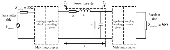
Figure 1.
PLC coupler composed of coupling circuit and impedance matching circuit [64].
For the complex conjugate matching case, the power reflection coefficient [59,68] can be expressed as
where is the input impedance of the power line channel, is the source internal impedance and is the complex conjugation of . In Equation (7), when , the power reflection coefficient is minimized (). In other words, when the modem (receiver/receiver) impedance is equal to the complex conjugate of the input power line impedance, the maximum power transfer is achieved. Based on the complex conjugate matching method, the authors of Refs. [69,70,71] designed a broadband impedance matching (BIM) circuit to maximize the power transfer.
Impedance matching networks designed using complex conjugate matching show a benefit in terms of the maximum signal power transfer. However, for a communication system, the SNR (Signal-to-Noise Ratio) is another important performance parameter. In Ref. [61], the authors point out that the received signal amplitude, instead of signal power, is important for communication purposes. The authors formulated the SNR in terms of signal amplitude and investigated the optimal receiver impedance for maximizing the SNR. Thus, a voltage maximization matching method was introduced in Ref. [59] to maximize the SNR, where voltage maximization matching operates at and ; it ultimately yields a higher received voltage and four times the active power than the complex conjugate matching. Table 1 lists the performance results of three impedance matching methods. As shown in Table 1, the voltage at the receiver () can be expressed as a function of and . The parameters B and D are the components of the ABCD matrix associated to the two-port network. is the determinant of the ABCD matrix H.

Table 1.
Performances of three impedance matching methods [59].
3.2. Based on Fixed or Variable Components / Structures
As discussed in Section 3.1, the band-pass matching couplers [62,63,64,65,66] often include a BPF circuit and an impedance matching circuit, where the circuit components are passive and the circuit structures are fixed. The band-pass matching coupler, with fixed structure and component values, is optimized for a specific frequency and a constant network access impedance. However, when various electronic devices or loads connected to the power line network are turned on/off or removed randomly, the network access impedance varies with time, frequency and location [23,32,33,34,35,36]. Therefore, fixed-structure band-pass matching couplers are inefficient and require adaptive impedance matching.
In PLC systems, adaptive impedance matching systems [72,73,74,75,76,77,78] have been designed for maximizing the power transfer. In Ref. [72], the magnitude of the power line access impedance is calculated by the sampled voltage and current of the power line network. A variable transformer and inductor are controlled by a digital circuitry, which implements a fuzzy logic algorithm to determine the transformer and inductor tap required to achieve the magnitude and phase matching. To increase the precision of the adaptive impedance matching, a larger number of taps are needed, which has the disadvantage of large size and high price.
An alternative adaptive impedance matching system, presented in Ref. [73], where an adaptive impedance matching system based on capacitor bank was designed, is shown in Figure 2a. The adaptive system includes a coupling circuit (capacitor and transformer), a decision circuit (micro-controller) and a capacitor bank. The power line access impedance, determined by access voltage and current, is measured using a coupling circuit, shown in Figure 2a. According to the low-valued real part of the network access impedance measured in the previous measurement campaign, the authors implement impedance matching by offsetting the imaginary part of the power line impedance (without considering the real part). When the imaginary part of the access impedance is offset by the capacitor bank, the output power reaches its maximum. The voltage and current (determine the output power) were measured using a coupling circuit and transmitted to the micro-controller for decision making. As shown in Figure 2a, when the output voltage of the amplifier is constant, only the measured peak current () determines the relay states in the capacitor bank, e.g., relays in the capacitor bank are fixed when the peak current is maximum. Figure 2b shows the comparison of the output signal voltage and current for the transmission with and without matching. As shown in Figure 2(b1), although the network access impedance varies with time, frequency and location, the phase of the output voltage and current is almost the same, while the maximum power transfer is obtained when the adaptive impedance matching system is used. As shown in Figure 2(b2), the phase of the output voltage and current is different due to the impedance mismatch. However, the adaptive system requires several off-chip components such as capacitors, switches and transformers, which increases the cost, size and weight of the system.
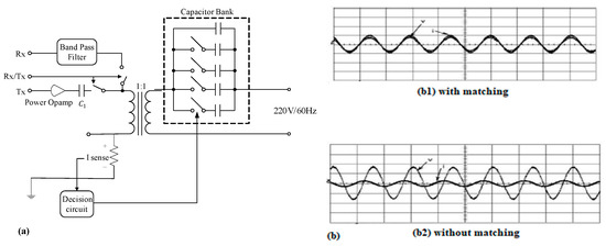
Figure 2.
(a) Adaptive impedance matching based on capacitors bank [73]; (b) comparison of output signal voltage and current for the transmission with and without matching [73].
In Ref. [74], an adaptive impedance matching system shown in Figure 3, composed of a coupling capacitor (), a transformer (), a fixed inductor (), and a variable inductor (), was proposed to achieve adaptive matching between transmitters and power line networks. According to the previous measurement campaign, the power line access impedance is mainly inductive. In Figure 3, power line access impedance is modeled via a variable inductor and resistor, whose values () are assumed by the measurement results. As shown in Figure 3, a variable inductor () was implemented based on VCGIC (Voltage-Controlled General Impedance Converter) to avoid the use of bulky passive inductors in the adaptive system. In the circuit, the transformer () is used to increase the current range of the variable inductor, which has the disadvantage of additional cost and size.
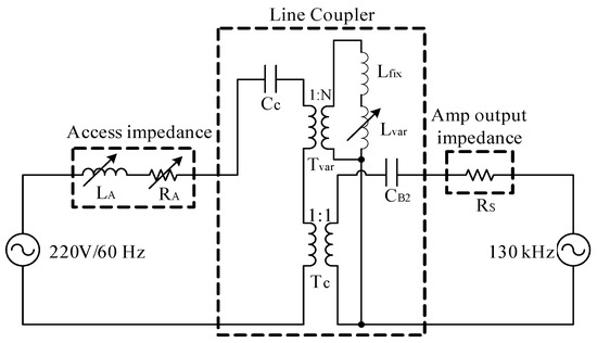
Figure 3.
Adaptive impedance matching system using VCGIC [74].
In Ref. [75], an RLC bandpass adaptive impedance matching system was designed, which includes a fixed inductor, a digital capacitor and a digital resistor. The digital capacitor is used as a variable capacitor that can be controlled via a micro-controller. As shown in Figure 4, the impedance of the source () and the power line channel () is measured and then fed back to the micro-controller to determine the value of the digital capacitor () and digital resistor () according to the conjugate matching approach. In Ref. [76], the authors further proposed a LCRC band-pass adaptive impedance matching system based on the system presented in Ref. [75]. The adaptive system includes a sensor that was used to measure the power line channel impedance and feedback into a micro-controller. The micro-controller adjusts the values of variable capacitors, inductor and resistor, based on the solving of a cubic equation in terms of L, for adaptive impedance matching. This system includes four variable components, which increase the complexity of control logic for adaptive impedance matching. Furthermore, the system composed of off-chip components, such as a transformer, will increase the cost and size of the system.
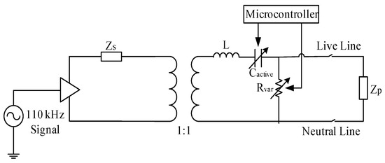
Figure 4.
RLC bandpass adaptive impedance matching circuit [75].
To avoid using a transformer, the authors of Refs. [77,78] design an adaptive impedance matching system by adjusting the circuit structure and component values of L-shaped networks shown in Figure 5a. The L-shaped network consists of a series component () and a shunt component (), with components oriented like the shape of the letter L. The method divides the Smith chart into eight parts and adopts a two-move strategy (L-shaped network) to perform the matching. The various moving paths on the chart represent different capacitors or inductors in the L-shaped matching network, e.g., a positive movement on the impedance circle indicates a series inductor and a negative movement indicates a series capacitor, while a positive movement on the admittance circle indicates a shunt capacitor and a negative movement indicates a shunt inductor.
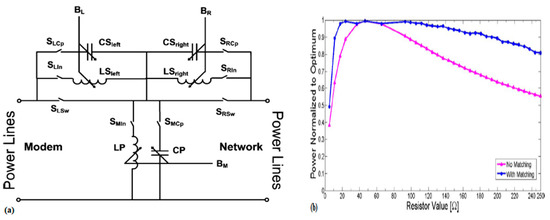
Figure 5.
(a) Circuit structure of the L-shaped adaptive matching networks [78]; (b) active power transferred into the network for the system with and without matching [78].
The adaptive impedance matching system [77,78] consists of three units: the measurement unit, the control unit, and the impedance matching unit. The measurement unit is used to obtain the access voltage and current. The control unit calculates the L-shaped matching circuit structural and component values according to the outputs of the measurement unit. Then, it sends out the corresponding control signal to the impedance matching unit. The impedance matching unit then automatically adjusts the L-shaped matching circuit structure and its component values to achieve adaptive impedance matching. Figure 5b shows that significant signal-power improvements are achieved for the adaptive matching system by comparing it to a transmission without impedance matching. We also observe that, although the network access impedance varies with time, frequency and location, an adaptive matching system exhibits greater robustness to network access impedance fluctuation than the transmission without matching. The adaptive matching system in Refs. [77,78] increases the matching regions by adjusting the structures of the L-shaped network. Although adaptive systems exhibit excellent impedance matching performance, they increase the system’s structural complexity.
Real-time measurement of power line access impedance is essential for an adaptive impedance matching system. However, few studies show a detailed real-time impedance measurement circuit for adaptive impedance matching in PLC; for example, in Ref. [72,73], the power line access impedance is calculated by measuring the voltage and current of the power line network. In Refs. [74,75,76], the power line access impedance is simply modeled by a variable resistor and inductor according to the previous measurement campaign. In the available reports [77,78], an input voltage and current measurement circuit, shown in Figure 6, are presented and determine the control logic of the L-shaped adaptive impedance matching system. In the figure, an Op-Amp (Operation Amplifier) is deployed between a small resistor to measure the current going through it, while the other Op-Amp was set-up to measure the voltage at the input of the adaptive matching system.
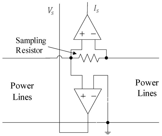
Figure 6.
The block diagram of voltage and current measurement circuit [78].
In Ref. [44], an adaptive antenna-matching technique for the L-shaped network was presented. In order to obtain the real and imaginary parts of the impedance in real-time, a sensing circuit and a quadrature detector circuit were designed. As shown in Figure 7a, the sensing circuit is designed to measure RF (Radio Frequency) voltage and RF current information. The RF voltage is obtained from a single-ended Op-Amp, while the RF current is determined from the differential voltage across a sensing element (), e.g., a fixed inductor.
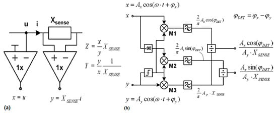
Figure 7.
(a) Sensing circuit used for measuring RF voltage and current information [44]; (b) Generic quadrature detector used for providing the real and imaginary parts of the detected impedance [44].
The two outputs ( and ) of the sensing circuit are fed to the quadrature detector circuit, shown in Figure 7b, to obtain the real and imaginary parts of the RF impedance. As shown in Figure 7b, an input signal is directly fed to mixer and is shifted by before it is fed to mixer , whereas, an input signal is directly fed to mixer and is limited in amplitude before it is fed to mixers and . The outputs of , and then pass through low pass filters. Finally, the resulting and outputs are each divided by the output of to obtain the real and imaginary parts of the detected impedance.
3.3. Based on the Implementation Cost
PLC technology is considered one of the most economical solutions for data communication, which leads to a tremendous economic competition between wireless and wired communication technologies. Therefore, cost minimization is ubiquitous in PLC.
In PLC, the impedance matching between PLC modems and power line networks is typically achieved through the use of a set of passive lumped-elements, e.g., transformers, capacitors and inductors. The coupling transformers are made up of a transformer and a capacitor; these coupling transformers are extensively used as PLC couplers for coupling, band-pass filtering and impedance matching. In Refs. [79,80], the authors investigated the role of the magnetizing inductance, leakage inductance and coupling capacitance of a coupling transformer. The coupling transformer shown in Figure 8 was designed in Refs. [81,82]; and refer to the voltage and impedance of the power line channel, whereas and are the voltage and impedance of the PLC modem, respectively. The coupling capacitor (C) is series resonant with the leakage inductance () of the transformer to function as a band pass filter to allow the communication signal to pass through while filtering out band noise (including the main voltage). The transformer with specific winding ratios was used to achieve impedance matching between a PLC modem and power line channel. In Refs. [83,84], an optimal winding ratio selection impedance matching technique was investigated, i.e., the coupling transformer implements dynamic impedance matching by changing its winding ratios.
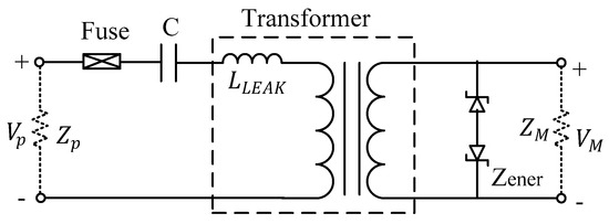
Figure 8.
Coupling transformer [81].
Although several benefits, e.g., voltage isolation and circuit protection, are gained from using the transformer, the cost and size of the transformers prevent them from being an economic and compact solution for PLC couplers. Therefore, to address these issues, L-C band-pass matching circuits [62,63,64,65,66] were used as alternatives to coupling transformers, which include a BPF circuit and an impedance matching circuit (see Section 3.1). The impedance matching circuit is made up of passive components, e.g., capacitors and inductors, that were used to achieve equal impedance matching between the characteristic impedance of the BPF and power line channel.
3.4. Based on Bandwidth
PLC couplers can be divided into two categories based on the PLC carrier frequencies (narrowband and broadband). Research related to narrowband PLC couplers were investigated in Refs. [62,63,64,65,66], where the narrowband band-pass matching coupling circuits were designed as alternatives to coupling transformers to achieve coupling, band-pass filtering and impedance matching. The impedance matching circuits are composed of lumped-elements, e.g., capacitors and/or inductors, and operated at 110 kHz to achieve impedance between the BPF and the power line channels. The couplers exhibit a fairly flat passband (95–125 kHz, CENELEC (European Committee for Electrotechnical Standardization [85]) B band) and obtain large power gains when compared with couplers without impedance matching. Furthermore, in Refs. [81,82,83,84], coupling transformers were designed as PLC couplers for low-frequency bands (0–500 kHz); thus, the impedance matching between PLC modems and power line channels are achieved by changing the winding ratios of the transformer.
In Ref. [71], a numerical optimization technique was used to design a broadband impedance matching circuit with 5th order ladder L-C topology, which exhibits the optimal gain between 1 MHz and 15 MHz. In Ref. [86], the authors designed a T-shaped coupling circuit for broadband PLC, whose frequencies range between 1.8 MHz–30 MHz. For other PLC applications, such as VPLCs, narrowband transmission systems cannot provide reliable connectivity due to prominent and severe noise interference [38,87]. In Refs. [77,78], the authors designed adaptive impedance matching systems (1–100 MHz) for VPLCs such that the impedance matching unit was composed of reactive components (capacitors and/or inductors). Adaptive impedance matching was achieved by adjusting the structures and component values of L-shaped networks.
3.5. Based on Impedance Types
Information about PLC network access impedance, in the band of interest, is an essential when designing an effective PLC coupler. PLC network access impedance is a complex-valued quantity that varies with time, frequency and location. Generally, the impedance magnitudes () and phase () are measured by a vector network analyzer (VNA) or transformed (computed) into real and imaginary impedance components to express the PLC network access impedance. Many researchers have measured network access impedance for narrowband and broadband PLC networks. In Ref. [88], the authors measured 86 commercial 50 Hz AC power distribution systems in the US and six European countries. The impedance magnitudes () were 0.3 –800 for 20 kHz–30 MHz. The real part of the impedance was 0–598 , whereas the imaginary part ranged between −800 (capacitive) and 686 (inductive) for 20 kHz–30 MHz. In Ref. [89], impedance was measured for both 120 and 240 V residential power distribution circuits for frequencies ranging between 5 kHz and 20 kHz. Our measurements show that the real part of the impedance was between 0 and 4 , whereas the imaginary part was between 1 and 12 . In Ref. [90], the authors carried out the impedance measurements for three different areas of Turkey at frequencies ranging between 10 kHz and 170 kHz (CENELEC A, B, C and D bands). The measured impedance magnitudes () were 3–17 , 1–17 , and 1–21 for rural, urban and the industrial PLC network, respectively. In Ref. [91], the authors performed impedance measurements at the narrowband (0–500 kHz) of the FCC (Federal Communications Commission) band. The access impedance magnitudes () ranged between 1 and 90 for different home scenarios.
The channel characteristics of VPLNs (Vehicular Power Line Networks) were investigated in [38,87,92,93], where the access impedance was measured under narrowband (0–500 kHz) and broadband (1–100 MHz) conditions for different vehicles. The access impedance of VPLNs (Vehicular power line networks) are complex-valued quantities that vary with location and time [33,34]. In Refs. [34,38], (summarized in Ref. [78]), the real part of the VPLN access impedance ranges from 0 to 250, while the imaginary part ranges between −175 and 150. An overview of the access impedance measurements is presented in Table 2, where R and X represent the real and imaginary components of the impedance, respectively.
Table 2.
The overview of the access impedance measurements for narrowband and broadband PLC.
According to the impedance types of the source/load, the impedance matching problems can be classified into three classes [94]. First, the real-to-real impedance matching problem (the filter or insertion loss problem), where impedance matching between a resistive source and resistive load is considered. Second, the real-to-complex impedance matching problem, where matching a resistive source to a complex load is considered. Third, the complex-to-complex impedance matching problem, where both source and load have complex-valued impedances.
In PLC, the internal impedance of the PLC transmitter/receiver (communication instrument) is usually assumed to be 50 [62,63,64,65,66]. As introduced in Section 3.1, impedance matching methods include equal impedance matching, complex conjugate matching and voltage-maximization matching. The equal impedance matching is necessary to achieve the real-to-real impedance matching between a resistive transmitter/receiver and a resistive power line characteristic impedance to minimize the signal reflection [62,64]. The complex conjugate matching is done to achieve the real-to-complex impedance matching between a resistive transmitter/receiver and a complex PLC network access impedance to maximize signal power transfer [69,70,71]. The voltage maximization matching is operated at and to achieve complex-to-complex impedance matching between a complex transmitter and a complex load to improve the SNR [59].
To overcome the location and time-varying nature of the PLC network access impedance, adaptive impedance matching systems [77,78] are designed to achieve real-to-complex impedance matching between a resistive transmitter/receiver and a complex power line network. The PLC network access impedance can be expressed by impedance magnitudes () and phase (). To facilitate the circuit design, some impedance matching approaches are based on impedance magnitudes () (the phases are not considered). For example, in Refs. [83,84], the power line impedance magnitude () ranges from 0.1 to 100 in the 0–500 kHz frequency band. The real-to-real impedance matching between the PLC transmitter/receiver and the power line channel was implemented by adjusting the winding ratio of the transformer.
3.6. Based on Component Types
According to the component types used for implementation, impedance matching circuits can be categorized into two classes: passive and active. In Refs. [81,82,83,84], some off-chip lumped components (passive), e.g., transformers, are used to achieve impedance matching between PLC modems and power line channels, by changing their winding ratios. However, the cost and size of transformers prevent them from being an economic and compact solution for PLC couplers. To address this issue, band-pass matching coupling circuits [62,63,64,65,66] are composed of lumped reactive components (passive), e.g., capacitors and/or inductors, which are formed as T-shaped, L-shaped or double L-shaped networks to achieve impedance matching between PLC modems and power line channels. However, the circuits [62,63,64] have complex structures and a larger number of passive components (capacitors and/or inductors) and switches, which ultimately increases the system’s cost and size.
In the ideal case, the variable components of a matching network can be achieved with tunable capacitors and tunable inductors. However, there are no available tunable inductors [41]. Furthermore, the limited tuning range of the available tunable capacitors cannot satisfy the required large capacitor values in the adaptive impedance matching circuit. On-chip active components can be implemented as an alternative for implementing variable inductors with large values, and thus, reduce the cost, size, and weight of adaptive systems. In Ref. [74], the authors used active components, e.g., GIC (General Impedance converter [95,96]), to replace the passive inductors. The impedance of an inductor can be implemented with an equivalent input impedance of VCGIC, thus avoiding the use of bulky passive inductors in adaptive systems. To overcome the high-current limitation of the VCGIC, an adaptive impedance matching technique using DIRC (digital inductive reactance convertor) was proposed in Ref. [97], where adaptive impedance matching could be achieved by adjusting the inductive reactance of the DIRC to the local capacitive reactance. The DIRC is also based on the active GIC. The inductive reactance of DIRC is achieved by adjusting the values of a digital resistor in the GIC, which makes the circuit a digital inductive reactance convertor.
The two adaptive impedance matching systems include off-chip transformers, which have the disadvantage of additional cost and size. To address this problem, a transformer-less impedance matching network was proposed in Ref. [98], where an active inductive circuit based on the GIC was designed to replace the bulky passive inductors and achieve adaptive impedance matching. In Ref. [99], an improved active inductance based on OA-C (Operational Amplifier- Capacitor) gyrator [100], was developed to be implemented for a PLC transceiver. The improved active inductor exhibits high impedance and high bandwidth that were required for wearable DC-PLC application.
3.7. Based on Voltage Levels
Over the past few decades, PLC technology has been widely investigated in a LV(Low Voltage) context, e.g., smart meter reading, smart home and smart grid. Various PLC couplers [62,63,64,65,66,81,82,83,84] with impedance matching have been designed. In recent years, the idea of using a MV (Medium Voltage) power distribution grid as a data communication backbone for monitoring, metering and control became an important topic.
To facilitate the implementation of MV PLC systems, some works have focused on the investigation of channel and noise characteristics, e.g., the noise levels [101], channel capacity [102], characteristic impedance [103], and earth path characterization [104] of MV power distribution grids. The MV PLC couplers require special components that withstand high differential voltages between the phases and ground, which make these devices more expensive and more difficult to implement than LV PLC couplers [3]. Some innovative MV PLC coupling solutions [105,106] have been proposed to replace commercial MV PLC couplers with less-expensive solutions by using a capacitive divider of voltage-detecting systems (VDS), which are usually already installed in the MV switchboards. Furthermore, an impedance matching circuit is designed between the transmitter and the MV capacitive divider to ensure maximum signal power transfer to the MV network. Subsequently, a low-cost smart meter architecture [107] for MV and LV distribution power grids has been investigated based on the use of VDS capacitive dividers as MV PLC couplers. Thus, the smart meter data collected by AMR at LV level, can be sent via the MV PLC coupler to MV centrators.
To enable communication between MV and LV grids, several studies have been carried out to investigate the possibility of transformers crossing the PLC signal. In Ref. [108], the impact of transformer energization level on PLC signal was investigated. The results show that when the PLC signal passes through distribution transformers, amplitude and phase variation will occurr. In Ref. [109], the influence of transformer impedances on the PLC signal was also investigated. The distribution transformer is an important component to achieve a communication between MV and LV grids and cannot be neglected due to significant losses. In Refs. [110,111], MV PLC couplers with transformers were designed for impedance matching at the signal input terminal of the MV power distribution grid. When the proper matched transformer is embedded in a MV PLC coupler, the maximum signal power is transmitted into the MV distribution grid.
3.8. Based on Channel Types
Many in-home power lines consist of three wires, e.g., phase (P), neutral (N) and protective earth (PE) wires, for power distribution. Typically, PLC couplers that work on SISO (Single Input Single Output) mode use the P-N port obtained from P and N wires to transmit and receive signals. Most PLC system studies use SISO mode due to their simplicity and low cost [3]. As disscussed in Section 3.1, Section 3.2, Section 3.3, Section 3.4, Section 3.5, Section 3.6 and Section 3.7, SISO PLC couplers with impedance matching are designed to achieve impedance matching between PLC modems and power line channels for maximum signal power transfer.
MIMO (Multiple Input and Multiple Output) techniques have been heavily investigated and haven proven their advantages, e.g., increased capacity and communication reliability in wireless communications [112]. A PLC system’s capacity increases when using MIMO techniques, as reported in Refs. [113,114,115]. A MIMO PLC channel is shown in Figure 9, where three wires provide three differential feeding and receiving possibilities for a MIMO PLC system with PLC transmitter and receiver modems [116,117]. However, according to Kirchhoff’s law (the sum of the three transmitted signals is zero), only two of the three possibilities can be used independently. Therefore, one has to extract or MIMO configurations (or MIMO when considering a common mode path [118]).
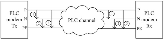
Figure 9.
MIMO PLC channel [116].
An in-home MIMO PLC coupler uses three (P-N, P-PE and N-PE) ports to transmit and receive signals. However, due to the impedance mismatch, the communication signals traveling in different paths have different times of arrival and attenuation at the receiver [119]. Furthermore, multipath propagation and load mismatches will cause multiple signal reflection in the PLC network [120]. Therefore, designing MIMO PLC couplers with impedance matching is an important method to deal with these issues, e.g., multipath interferance, attenuation and signal reflection.
3.9. Based on Transmittal Modes
In PLC, most PLC couplers have been designed for HD (Half-Duplex) operation. IBFD (In-Band Full Duplex) is an attractive technology that boosts the communication throughput by enabling concurrent data transmission and reception on the same frequency band. IBFD technology has been widely investigated in DSL (Digital Subscriber Line) [121,122] and wireless communication systems [123,124]. Recently, IBFD has been introducted in a PLC context [125] and some new echo canceling approaches have been proposed.
To allow the simultaneous bidirectional in-band communication, a hybrid coupler [126] is deployed between the transceiver and the power line channel. However, due to the impedance mismatch of the power line channel, part of the transmitted signal can leak into the receiver, causing self-interference (SI), or simply an echo. The main task to solve when designing a PLC-IBFD system is to enhance SI reduction or echo cancellation.
In Ref. [127], an active hybrid coupler with impedance matching capabilities was designed to isolate the receiver. As shown in Figure 10, P1, P2 and P3 connected to the transmitter, the PLC channel and the receiver, respectively; these are the three ports of the hybrid coupler. , and are the impedances of P1, P2 and P3, respectively. The terms and are the voltage and output impedance, respectively, of the transmitter’s AFE (Analog Front-End). Typically, the is 3. At port P1, to obtain maximum voltage transfer, is sufficent to achieve impedance bridging. A typical PLC channel impedane is 100. At port P2, to prevent signal reflections from the hybrid coupler to the PLC channel, impedance matching () between and is required. At port P3, the receiver-end usually has a high impedance, e.g., . To achieve impedance matching at P3, . In Ref. [128], to achieve impedance matching at P2, the active hybrid coupler is equipped with a fixed value resistance of , which is set to match the typical power line impedance.
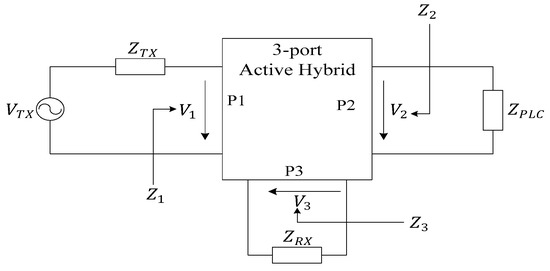
Figure 10.
Port connections of the active hybrid [127].
Both solutions [127,128] equip the active circulator (hybrid) with a fixed value resistance, e.g., 100, to match with the PLC channel. The systems suffer from poor echo cancellation performance due to the fluctuing channel impedance. To overcome this issue, an adaptive active hybrid coupler [129] was designed, where the impedance of the hybrid coupler at port P2 is tuned using a classical LMS approach to best match with the PLC channel and to maximize the SI reduction. Subsequently, an analog full-duplex amplification and forward relay [130] comprised of a circulator with an impedance matching circuit, an analog filter and an amplifier, was proposed to provide incoming signal amplification for the PLC. To reduce the echo, the matching impedance of the hybrid coupler is tuned to the input impedance of the PLC network.
3.10. Classification of the Impedance Matching Solutions in PLC
As discussed in Section 3.1, Section 3.2, Section 3.3, Section 3.4, Section 3.5, Section 3.6, Section 3.7, Section 3.8 and Section 3.9, PLC impedance matching problems can be classified according to a variety of considerations. These classifications are compiled in Table 3, which provides an overview of classification methods.
Table 3.
Classification methods for PLC impedance matching techniques.
To provide a more substantial overview of existing state-of-the-art research in impedance matching, the literature review described is compiled in Table 4.
Table 4.
Review of related works in PLC.
4. Future Trends and Works
To achieve reliable and effective communication over power line channels, effective impedance matching circuits are essential for PLC systems. Due to the harsh channel environments and the location- and time-varying nature of network access impedance, finding appropriate impedance matching solutions can be a considerable challenge. Although great effort has been invested in impedance matching research, there are some important concerns that need to be addressed. We provide a set of open problems and potential research directions below.
- In PLC, lumped matching elements, e.g., capacitors and inductors, are usually assumed lossless. In practice, the gain obtained from an impedance matching network can be partly undone by the insertion loss of the matching network in the presence of non-ideal elements. If the matching elements are lossy, traditional impedance matching approaches, such as conjugate matching, do not guarantee maximum power transfer to the receiver. Furthermore, any additional losses to the matching network may be particularly severe at a specific frequency, which will severely degrade efficiency [43]. In PLC, few works have investigated the impedance matching problems when non-ideal matching elements are considered. Therefore, characterizing and minimizing insertion losses of matching networks are important issues to resolve.
- Inaccurate impedance measurements have a negative impact on the performance of impedance matching solutions. The average power line impedance used in some work, produces poor quality impedance matching circuits. However, the network access impedance that varies with time, frequency and location, leads to impedance measurement challenges. Therefore, designing an accurate and effective impedance measurement circuit is of particular importance.
- In practice, matching networks with fewer components are preferred. For PLC, two-element, L-shaped matching networks have been investigated. However, three-element matching networks, which consist of three variable reactance components, facilitate better impedance matching capabilities (because they have a larger matching region than L-shaped networks). For PLC, few researchers have studied three-element matching network solutions required for real-to-complex impedance matching in PLCs, e.g., П-shaped networks and T-shaped networks.
- A large number of passive capacitors and inductors increase the structural complexity and size of the system; these components also impose an extra burden on the control logic for adaptive impedance matching. An ideal adaptive impedance matching system can be implemented by a matching network of tunable capacitors (voltage-controlled) and tunable inductors. However, there are no available tunable inductors. Therefore, implementing a tunable or active inductor with large variable values is an important issue to be addressed.
- More recently, IBFD has been introduced to the PLC context. In IBFD-PLC, the main task to solve is to enhance SI reduction or echo cancellation when designing a PLC-IBFD system. The SI or echo that influences communication reliability will emerge when there is an impedance mismatch between the hybrid coupler and the power line channel. Therefore, designing an effective hybrid coupler with impedance matching is an important issue to be solved.
5. Conclusions
Impedance matching technology has many obstacles to surpass before an efficient and effective PLC coupler can be designed. In this paper, we discussed the tradeoffs needed to design an effective impedance matching network, such as gain and insertion loss, efficiency and cost, bandwidth and attenuation, and matching region and structure. Additionally, we provided a classification of impedance matching solutions. We also introduced several suggestions about the implementation of system components. These suggestions could potentially be used to design a desired impedance matching circuit given revised considerations.
Finally, we summarize some important issues to be solved and point out some future research directions that facilitate the improvement of PLC impedance matching solutions. Therefore, this review provides a useful framework for researchers that want to quickly understand impedance matching principles and facilitate impedance matching circuit design.
Author Contributions
Investigation, data collection and analysis, writing—original draft preparation, editing, B.W; review, funding acquisition, Z.C.
Funding
This work is supported by Postgraduate Research & Practice Innovation Program of Jiangsu Province (KYCX18_0888), National Natural Science Foundation of China (61372044), Natural Science Foundation of the Jiangsu Higher Education Institutions of China (14KJA510002) and Natural Science Foundation of Chuzhou University (zrjz2017008).
Acknowledgments
The authors would like to thank Prof. Yongjin Wang and Prof. Guanxiang Du for providing access to their laboratory instruments, as well as Hongguan Wang and Zhiyuan Yang for helps while writing this paper.
Conflicts of Interest
The authors declare no conflict of interest.
References
- Ferreira, H.C.; Lampe, L.; Newbury, J.; Swart, T.G. Power Line Communications: Theory and Applications for Narrowband and Broad-band Communications over Power Lines; Wiley: Hoboken, NJ, USA, 2010. [Google Scholar]
- Schwartz, M. Carrier-wave telephony over power lines: Early history [History of Communications]. IEEE Commun. Mag. 2009, 47, 14–18. [Google Scholar] [CrossRef]
- Costa, L.G.S.; Queirz, A.C.M.; Adebisi, B.; Ribeiro, M.V. Coupling for power line communication: A Survey. J. Commun Inf. Syst. 2017, 32, 8–22. [Google Scholar] [CrossRef]
- Sanchez-Pacheco, F.J.; Sotorrio-Ruiz, P.J.; Heredia-Larrubia, J.R.; Perez-Hidalgo, F.; Cardona, M.S. PLC-Based PV Plants Smart Monitoring System: Field Measurements and Uncertainty Estimation. IEEE Trans. Instrum. Meas. 2014, 63, 2215–2222. [Google Scholar] [CrossRef]
- Choi, M.; Ju, S.; Lim, Y. Design of integrated meter reading system based on power-line communication. In Proceedings of the 2008 IEEE International Symposium on power line communications and its applications, Jeju City, Korea, 2–4 April 2008. [Google Scholar]
- Li, M.; Lin, H. Design and Implementation of Smart Home Control Systems Based on Wireless Sensor Networks and Power Line Communications. IEEE Trans. Ind. Electron. 2015, 62, 4430–4442. [Google Scholar] [CrossRef]
- Vitale, G. Characterization of a DC grid for Power Line Communications in smart grids. In Proceedings of the Control and Modeling for Power Electronics (COMPEL), Santander, Spain, 22–25 June 2014. [Google Scholar]
- Sirinamaratana, P.; Leelarasmee, E.; Pora, W. A Series DC Power Line Communication and its application to monitoring photo-voltaic strings. J. Circuits Syst. Comput. 2013, 22, 1340010. [Google Scholar] [CrossRef]
- Mao, W.; Zhang, X.; Cao, R.; Wang, F.; Zhao, T.; Xu, L. A Research on Power Line Communication Based on Parallel Resonant Coupling Technology in PV Module Monitoring. IEEE Trans. Ind. Electron. 2018, 65, 2653–2662. [Google Scholar] [CrossRef]
- Napoli, F.D.; Guerriero, P.; D’Alessandro, V.; Daliento, S. A power line communication on DC bus with photovoltaic strings. In Proceedings of the 3rd Renewable Power Generation Conference, Naples, Italy, 24–25 September 2014. [Google Scholar]
- Sirinamaratana, P.; Leelarasmee, E. Circuits for data communication through DC power line in solar farm. In Proceedings of the IEEE International Conference of Electron Devices and Solid-state Circuits (EDSSC), Hong Kong, China, 3–5 June 2013. [Google Scholar]
- Shukla, A.; Dahiya, R. 8-PSK Power Line Communication Analysis and Modeling for Renewable Smart Grids. In Proceedings of the 2015 International Conference on Signal Processing and Communication (ICS), Noida, India, 16–18 March 2015. [Google Scholar]
- Degauque, P.; Stievano, I.; Pignari, S.; Degardin, V.; Canavero, F. Power-Line Communication: Channel Characterization and Modeling for Transportation Systems. IEEE IEEE Veh. Technol. Mag. 2015, 10, 28–37. [Google Scholar] [CrossRef]
- Takanashi, M.; Takahashi, A.; Tanaka, H.; Hayashi, H. High-Voltage Power Line Communication in a Hybrid Vehicle. IEICE Trans. Fundam. Electron. Commun. Comput. Sci. 2017, 100, 1705–1713. [Google Scholar] [CrossRef]
- Barmada, S.; Bellanti, L.; Raugi, M.; Tucci, M. Analysis of Power-Line Communication Channels in Ships. IEEE Trans. Veh. Technol. 2010, 59, 3161–3170. [Google Scholar] [CrossRef]
- Antoniali, M.; Tonello, A.M.; Lenardon, M.; Qualizza, A. Measurements and analysis of PLC channels in a cruise ship. In Proceedings of the IEEE International Symposium Power Line Communications Applications, Udine, Italy, 3–6 April 2011. [Google Scholar]
- Degardin, V.; Junqua, I.; Lienard, M.; Degauque, P.; Bertuol, S. Theoretical Approach to the Feasibility of Power-Line Communication in Aircrafts. IEEE Trans. Veh. Technol. 2013, 62, 1362–1366. [Google Scholar] [CrossRef]
- Chedid, M.; Belov, I.; Leisner, P. Low Power High Bandwidth Power-Line Communication Network for Wearable Applications. In Proceedings of the Fifth International Conference on Body Area Networks, New York, NY, USA, 10–12 September 2010. [Google Scholar]
- Lin, H.; Hu, J.; Zhou, X.; Lu, Z. New DC Grid Power Line Communication Technology Used in Networked LED Driver. Energies 2018, 11, 3531. [Google Scholar] [CrossRef]
- Rensburg, P.A.J.V.; Snyders, A.J.; Ferreira, H.C. Modeling of Coupling Diversity for Extra-Low-Voltage Power-Line Communication Networked LED Lighting in Smart Buildings. IEEE J. Emerg. Sel. Top. Power Electron. 2018, 6, 224–1234. [Google Scholar]
- Héla, G.; Bali, M.C.; Duval, F. Coupling interface circuit design for experimental characterization of the narrowband power line communication channel. In Proceedings of the 2012 IEEE International Symposium on Electromagnetic Compatibility, Pittsburgh, PA, USA, 6–10 August 2012. [Google Scholar]
- Ferreira, H.C.; Grove, H.M.; Hooijen, O. Power line communications: An overview. In Proceedings of the IEEE. AFRICON’96, Stellenbosch, South Africa, 27–27 September 1996. [Google Scholar]
- Tang, L.T.; So, P.L.; Gunawan, E. Characterization of power distribution lines for high-speed data transmission. In Proceedings of the 2000 International Conference on Power System Technology, Perth, Australia, 4–7 December 2000. [Google Scholar]
- Rasool, B.; Rasool, A.; Khan, I. Impedance Characterization of Power Line Communication Networks. Arab. J. Sci. Eng. 2014, 39, 6255–6267. [Google Scholar] [CrossRef]
- Esmailian, T.; Kschischang, F.R.; Gulak, P.G. In-building power lines as high-speed communication channels: Channel characterization and a test channel ensemble. Int. J. Commun. Syst. 2003, 16, 381–400. [Google Scholar] [CrossRef]
- Bausch, J.; Kistner, T.; Babic, M. Characteristics of Indoor Power Line Channels in the Frequency Range 50-500 kHz. In Proceedings of the 2006 IEEE International Symposium on Power Line Communications and Its Applications, Orlando, FL, USA, 30 October 2006. [Google Scholar]
- Joshi, R.P.; Bhosale, S.; Patil, P.H. Analysis and Simulation of Noise in Power Line Communication Systems. In Proceedings of the First International Conference on Emerging Trends in Engineering and Technology, Washington, DC, USA, 16–18 July 2008. [Google Scholar]
- Katayama, M.; Yamazato, T.; Okada, H. A mathematical model of noise in narrowband power line communication systems. IEEE J. Sel. Areas Commun. 2006, 24, 1267–1276. [Google Scholar] [CrossRef]
- Huck, T.; Schirmer, J.; Hogenmuller, T. Tutorial about the implementation of a vehicular high speed communication system. In Proceedings of the International Symposium on Power Line Communications and Its Applications, Vancouver, BC, Canada, 6–8 April 2005. [Google Scholar]
- Lin, J.; Zhao, T.; Liu, G.Q. The design of active power filter based on power line carrier communication. Adv. Mater. Res. 2013, 614, 1587–1590. [Google Scholar]
- Rastogi, M.; Mitra, D.K.; Bhattacharya, A. A Novel Implementation of Bidirectional Coupling Circuit for Broadband, High-Voltage, Power-Line Communications. In Proceedings of the 2005 Asia-Pacific Conference on Communications, Perth, Australia, 3–5 October 2005. [Google Scholar]
- Zhu, Q.; Chen, Z.; He, X. Resource Allocation for Relay-Based OFDMA Power Line Communication System. Electronics 2019, 8, 125. [Google Scholar] [CrossRef]
- Antoniali, M.; Piante, M.D.; Tonello, A.M. PLC noise and channel characterization in a compact electrical car. In Proceedings of the IEEE 17th International Symposium on Power Line Communications and Its Applications, Johannesburg, South Africa, 24–27 March 2013. [Google Scholar]
- Degardin, V.; Lienard, M.; Degauque, P. Impulsive Noise Characterization of In-Vehicle Power Line. IEEE Trans. Electromagn. Compat. 2008, 50, 861–868. [Google Scholar] [CrossRef]
- Nguyen, T.V.; Petit, P.; Sawicki, J.P. DC Power-line Communication based Network Architecture for HVDC Distribution of a Renewable Energy System. Energy Procedia 2014, 50, 147–154. [Google Scholar] [CrossRef][Green Version]
- Marrocco, G.; Statovci, D.; Trautmann, S. A PLC broadband channel simulator for indoor communications. In Proceedings of the 17th IEEE International Symposium on Power Line Communications and Its Applications, Johannesburg, South Africa, 24–27 March 2013. [Google Scholar]
- Tonello, A.M.; Versolatto, F.; Pittolo, A. In-Home Power Line Communication Channel: Statistical Characterization. IEEE Trans. Commun. 2014, 62, 2096–2106. [Google Scholar] [CrossRef]
- Mohammadi, M.; Lampe, L.; Lok, M. Measurement study and transmission for in-vehicle power line communication. In Proceedings of the 2009 IEEE International Symposium on Power Line Communications and Its Applications, Dresden, Germany, 29 March–1 April 2009. [Google Scholar]
- Barmada, S.; Raugi, M.; Tucci, M. Power line communication in a full electric vehicle: Measurements, modelling and analysis. In Proceedings of the 2010 IEEE International Symposium on Power Line Communications and Its Applications, Rio de Janeiro, Brazil, 28–31 March 2010. [Google Scholar]
- Stievano, I.S.; Canavero, F.G.; Garcia, V.W.R. Multipath modeling of automotive power line communication channels. IEEE Trans. Ind. Inf. 2014, 10, 1381–1391. [Google Scholar] [CrossRef]
- Gu, Q.; Luis, J.R.D.; Morris, A.S.I. An Analytical Algorithm for Pi-Network Impedance Tuners. IEEE Trans. Circuits Syst. Regul. Pap. 2011, 58-I, 2894–2905. [Google Scholar] [CrossRef]
- Gu, Q. RF Tunable Devices and Subsystems: Methods of Modeling, Analysis and Applications; Springer International Publishing: Cham, Switzerland, 2015. [Google Scholar]
- Chen, Y.; Chiu, C. Insertion Loss Characterization of Impedance Matching Networks for Low-Power Rectennas. IEEE Trans Compon. Packag. Manuf. Technol. 2018, 8, 1632–1641. [Google Scholar] [CrossRef]
- Van Bezooijen, A.; De Jongh, M.A.; Van Straten, F.; Mahmoudi, R.; Van Roermund, A.H. Adaptive Impedance-Matching Techniques for Controlling L Networks. IEEE Trans. Circuits Syst. Regul. Pap. 2010, 57, 495–505. [Google Scholar] [CrossRef]
- Freitas, V.; Arnould, J.D.; Ferrari, P. General expression for tunable matching network efficiency in the case of complex impedances. Microw. Opt. Technol. Lett. 2015, 57, 1160–1166. [Google Scholar] [CrossRef]
- Han, Y.; Perreault, D.J. Analysis and Design of High Efficiency Matching Networks. IEEE Trans. Power Electron. 2006, 21, 1484–1491. [Google Scholar] [CrossRef]
- Martins, G.C.; Serdijn, W.A. Multistage Complex-Impedance Matching Network Analysis and Optimization. IEEE Trans. Circuits Syst. Express Br. 2016, 63, 833–837. [Google Scholar] [CrossRef]
- Chappidi, C.K.R.; Sengupta, K. Globally Optimal Matching Networks with Lossy Passives and Efficiency Bounds. IEEE Trans. Circuits Syst. Regul. Pap. 2018, 65, 257–269. [Google Scholar] [CrossRef]
- Chappidi, C.K.R.; Sengupta, K. Methods for finding globally maximum-efficiency impedance matching networks with lossy passives. In Proceedings of the 2015 IEEE Custom Integrated Circuits Conference (CICC), San Jose, CA, USA, 28–30 September 2015. [Google Scholar]
- Stiri, S.; Chaoub, A.; Maliki, T.E. Realization of a low-cost impedance matching circuit for stable power line communications: From testbeds to practical implementation. In Proceedings of the 19th IEEE Mediterranean Electrotechnical Conference (MELECON), Marrakech, Morocco, 2–7 May 2018. [Google Scholar]
- Farias, L.D.R.; Monteiro, L.F.; Leme, M.O. Empirical Analysis of the Communication in Industrial Environment Based on G3-Power Line Communication and Influences from Electrical Grid. Electronics 2018, 7, 1–17. [Google Scholar]
- Cortés, J.A.; Sanz, A.; Estopinán, P. Analysis of narrowband power line communication channels for advanced metering infrastructure. EURASIP J. Adv. Signal Process. 2015, 27, 1–13. [Google Scholar] [CrossRef]
- Pukale, R.S.; Bavache, S.V.; Kashid, S.N. Automatic meter reading of electricity by using power line communication. In Proceedings of the 2017 International Conference on Innovations in Green Energy and Healthcare Technologies (IGEHT), Coimbatore, India, 16–18 March 2017. [Google Scholar]
- Božanić, M.; Sinha, S. Power Amplifiers for the S-, C-, X- and Ku bands: An EDA Perspective; Springer International Publishing: Cham, Switzerland, 2016. [Google Scholar]
- Thompson, M.; Fidler, J.K. Determination of the impedance matching domain of impedance matching networks. IEEE Trans. Circuits Syst. Regul. Pap. 2004, 51, 2098–2106. [Google Scholar] [CrossRef]
- Chung, B.K. Q-based design method for T network impedance matching. Microelectron. J. 2006, 37, 1007–1011. [Google Scholar] [CrossRef]
- Sun, Y.; Fidler, J.K. Design of impedance matching networks. In Proceedings of the IEEE International Symposium on Circuits and Systems, London, UK, 30 May–2 June 1994. [Google Scholar]
- Schmidt, M.; Lourandakis, E.; Leidl, A. A comparison of tunable ferroelectric П- and T-matching networks. In Proceedings of the 2007 European Microwave Conference, Munich, Germany, 9–12 October 2007. [Google Scholar]
- De Piante, M.; Tonello, A.M. On Impedance Matching in a Power Line Communication System. IEEE Trans. Circuits Syst. Express Br. 2016, 63, 653–657. [Google Scholar] [CrossRef]
- De Piante, M.; Tonello, A.M. Impedance Matching and Channel Capacity in Power Line Communication Systems. In Proceedings of the 2017 IEEE International Symposium on Power Line Communications and its Applications (ISPLC), Madrid, Spain, 3–5 April 2017. [Google Scholar]
- Antoniali, M.; Tonello, A.M.; Versolatto, F. A Study on the optimal receiver impedance for SNR maximization in broadband PLC. J. Electr. Comput Eng. 2013, 2013, 1–11. [Google Scholar] [CrossRef]
- Sibanda, M.P.; Rensburg, P.A.J.V.; Ferreira, H.C. Passive, transformerless coupling circuitry for narrow-band power-line communications. In Proceedings of the 2009 IEEE International Symposium on Power Line Communications and Its Applications, Dresden, Germany, 29 March–1 April 2009. [Google Scholar]
- Sibanda, M.P.; Rensburg, P.A.J.V.; Ferreira, H.C. Impedance matching with low-cost, passive components for narrowband PLC. In Proceedings of the 2011 IEEE International Symposium on Power Line Communications and Its Applications, Udine, Italy, 3–6 April 2011. [Google Scholar]
- Wang, B.; Cao, Z.; Luan, Z. Design and Evaluation of Band-Pass Matching Coupler for Narrow-Band DC Power Line Communications. J. Circuits Syst. Comput. 2019, 28, 1–19. [Google Scholar] [CrossRef]
- Sibanda, M.P.; Rensburg, P.A.J.V.; Ferreira, H.C. A compact economical PLC band-pass coupler with impedance matching. In Proceedings of the IEEE 17th International Symposium on Power Line Communications and Its Applications, Johannesburg, South Africa, 24–27 March 2013. [Google Scholar]
- Rensburg, P.A.J.V.; Sibanda, M.P.; Ferreira, H.C. Integrated Impedance-Matching Coupler for Smart Building and Other Power-Line Communications Applications. IEEE Trans. Power Deliv. 2015, 30, 949–956. [Google Scholar] [CrossRef]
- Brison, M.; Bensetti, M.; Lacerda, R.D. Optimised PLC power transfer on avionic DC Power Lines: Coupling circuit and lightning protection. In Proceedings of the 2017 IEEE International Symposium on Power Line Communications and Its Applications, Madrid, Spain, 3–5 April 2017. [Google Scholar]
- Rahola, J. Power Waves and Conjugate Matching. IEEE Trans. Circuits Syst-II Express Br. 2008, 55, 92–96. [Google Scholar] [CrossRef]
- Araneo, R.; Celozzi, S.; Lovat, G. Design of impedance matching couplers for power line communications. In Proceedings of the 2009 IEEE International Symposium on Electromagnetic Compatibility, Austrin, TX, USA, 17–21 August 2009. [Google Scholar]
- Araneo, R.; Celozzi, S.; Lovat, G. Multi-port impedance matching technique for power line communications. In Proceedings of the 2011 IEEE International Symposium on Power Line Communications and Its Applications, Udine, Italy, 3–6 April 2011. [Google Scholar]
- Yang, S.; Li, H.; Goldberg, M. Broadband Impedance matching circuit design and using Numerical optimization techniques and field Measurements. In Proceedings of the 2007 IEEE International Symposium on Power Line Communications and Its Applications, Pisa, Italy, 26–28 March 2007. [Google Scholar]
- Munoz, F.; Carvajal, R.G.; Torralba, A. ADAPT: Mixed-signal ASIC for impedance adaptation in power line communications using fuzzy logic. In Proceedings of the 25th Annual Conference of the IEEE Industrial Electronics Society, San Jose, CA, USA, 29 November–30 3 December 1999. [Google Scholar]
- Choi, W.H.; Park, C.Y. A simple line coupler with adaptive impedance matching for Power line communication. In Proceedings of the 2007 IEEE International Symposium on Power Line Communications and Its Applications, Pisa, Italy, 26–28 March 2007. [Google Scholar]
- Park, C.Y.; Jung, K.H.; Choi, W.H. Coupling circuitary for impedance adaptation in power line communications using VCGIC. In Proceedings of the 2008 IEEE International Symposium on Power Line Communications and Its Applications, Jeju City, Korea, 2–4 April 2008. [Google Scholar]
- Rui, C.P.; Barsoum, N.N.; Ming, A.W.K. Adaptive impedance matching network with digital capacitor in narrowband power line communication. In Proceedings of the 2013 IEEE International Symposium on Industrial Electronics, Taipei, Taiwan, 28–31 May 2013. [Google Scholar]
- Chin, P.R.; Wong, A.K.M.; Wong, K.I. Modelling of LCRC adaptive impedance matching circuit in narrowband power line communication. In Proceedings of the IEEE 11th International Conference on Power Electronics & Drive Systems, Sydney, Australia, 9–12 June 2015. [Google Scholar]
- Taherinejad, N.; Lampe, L.; Mirabbasi, S. Adaptive impedance matching for Vehicular Power Line Communication systems. In Proceedings of the 18th IEEE International Symposium on Power Line Communications and Its Applications, Glasgow, UK, 30 March–2 April 2014. [Google Scholar]
- Taherinejad, N.; Lampe, L.; Mirabbasi, S. An Adaptive Impedance-Matching System for Vehicular Power Line Communication. IEEE Trans. Veh. Technol. 2017, 66, 927–940. [Google Scholar] [CrossRef]
- Rensburg, P.A.J.V.; Ferreira, H.C. The role of magnetizing and leakage inductance in transformer coupling circuitry. In Proceedings of the 8th International Symposium on Power-Line Communications and Its Applications, Zaragoza, Spain, 31 March–2 April 2004. [Google Scholar]
- Rensburg, P.A.J.V.; Ferreira, H.C. Coupling circuitry: Understanding the functions of different components. In Proceedings of the 7th International Symposium on Power-Line Communications and Its Applications, Kyoto, Japan, 26–28 March 2003. [Google Scholar]
- Rensburg, P.A.J.V.; Ferreira, H.C. Design of a bidirectional impedance adapting transformer coupling circuit for low-voltage power-line communications. IEEE Trans. Power Deliv. 2005, 20, 64–70. [Google Scholar]
- Rensburg, P.A.J.V.; Ferreira, H.C. Step-by step design of a coupling circuit with bi-directional transmission capabilities. In Proceedings of the 8th IEEE International Symposium on Power Line Communications and Its Applications, Zaragoza, Spain, 31 March–2 April 2004. [Google Scholar]
- Rensburg, P.A.J.V.; Ferreira, H.C. Coupler winding ratio selection for effective narrowband power-line communications. IEEE Trans. Power Deliv. 2008, 23, 140–149. [Google Scholar] [CrossRef]
- Rensburg, P.A.J.V.; Ferreira, H.C. Design and evaluation of a dual impedance-adapting power-line communications coupler. IEEE Trans. Power Deliv. 2010, 25, 667–673. [Google Scholar] [CrossRef]
- European Committee for Electrotechnical Standardization (CENELEC). Signalling on low-voltage electrical installations in the frequency range 3 kHz to 148.5 kHz—part 1: General requirements, frequency bands and electromagnetic disturbances. European Standard EN 50065–1. Available online: http://www.doc88.com/p-1048982237653.html (accessed on 10 September 2019).
- Martinez, B.; Cante, N.; Limas, M. Design of a T-coupling circuit for PLC on broadband. In Proceedings of the 2014 IEEE Colombian Conference on Communications and Computing, Bogota, Colombia, 4–6 June 2014. [Google Scholar]
- Pittolo, A.; Piante, M.D.; Versolatto, F. In-Vehicle Power Line Communication: Differences and Similarities Among the In-Car and the In-Ship Scenarios. IEEE Veh. Technol. Mag. 2017, 11, 43–51. [Google Scholar] [CrossRef]
- Malack, J.A.; Engstrom, J.R. RF Impedance of United states and European Power Lines. IEEE Trans. Electromag. Compat. 1976, 18, 36–38. [Google Scholar] [CrossRef]
- Vines, R.M.; Trussell, H.J.; Shuey, K.C. Impedance of Residential Power-Distribution Circuit. IEEE Trans. Electromag. Compat. 1985, 27, 6–12. [Google Scholar] [CrossRef]
- Cavdar, H.; Karadeniz, E. Measurements of Impedance and Attenuation at CENELEC Bands for Power Line Communications Systems. Sensors 2008, 8, 8027–8036. [Google Scholar] [CrossRef] [PubMed]
- Pasdar, A.M.; Cavdar, I.H.; Sozer, Y. Power-Line Impedance Estimation at FCC Band Based on Intelligent Home Appliances Status Detection Algorithm Through Their Individual Energy and Impedance Signatures. IEEE Trans. Power Deliv. 2014, 29, 1407–1416. [Google Scholar] [CrossRef]
- Lienard, M.; Carrion, M.O.; Degardin, V. Modeling and Analysis of In-Vehicle Power Line Communication Channels. IEEE Trans. Veh. Technol. 2008, 57, 670–679. [Google Scholar] [CrossRef]
- Taherinejad, N.; Rosales, R.; Lampe, L. Channel characterization for power line communication in a hybrid electric vehicle. In Proceedings of the 2012 IEEE International Symposium on Power Line Communications and Its Applications, Beijing, China, 27–30 March 2012. [Google Scholar]
- Yarman, B.S.; Şengül, M.; Trabert, J. Design of wideband matching networks for wireless communication systems. In Proceedings of the Second International Symposium on Communications, Control and Signal Processing, Marrakech, Morocco, 13–15 March 2006. [Google Scholar]
- Antoniou, A. Gyrator using operational amplifier. Electron. Lett. 1967, 3, 350–352. [Google Scholar] [CrossRef]
- Antoniou, A. Realisation of gyrators using operational amplifiers, and their use in RC-active-network synthesis. Proc. Inst. Electr. Eng. 1969, 116, 1838–1850. [Google Scholar]
- Sun, Y.; Amaratunga, G.A.J. High-current adaptive impedance matching in narrowband power-line communication systems. In Proceedings of the 2011 IEEE International Symposium on Power Line Communications and Its Applications, Udine, Italy, 3–6 April 2011. [Google Scholar]
- Nisbet, P.; He, M.; Zhao, L. Transformerless impedance matching networks for automotive power line communication. J. Electr. Electron. Eng. Res. 2014, 6, 13–20. [Google Scholar]
- Chedid, M.; Nilsson, H.; Johansson, A. Realization of an active inductance for a low power high bandwidth DC power line communication network transceiver. AEU Int. J. Electron. Commun. 2010, 64, 947–952. [Google Scholar] [CrossRef]
- Shima, T. Application of the inductor multiplier. In Proceedings of the 13th IEEE international conference on electronics, circuits and systems, Nice, France, 10–13 December 2006. [Google Scholar]
- Milioudis, A.N.; Syranidis, K.N.; Andreou, G.T.; Labridis, D.P. Modeling of Medium-Voltage Power-Line Communication Systems Noise Levels. IEEE Trans. Power Deliv. 2013, 28, 2004–2013. [Google Scholar] [CrossRef]
- Milioudis, A.; Andreou, G.; Labridis, D. Optimum transmitted power spectral distribution for broadband power line communication systems considering electromagnetic emissions. Electr. Power Syst. Res. 2016, 140, 958–964. [Google Scholar] [CrossRef]
- Zhao, H.; Zhang, W.; Wang, Y. Characteristic Impedance Analysis of Medium-Voltage Underground Cables with Grounded Shields and Armors for Power Line Communication. Electronics 2019, 8, 571. [Google Scholar] [CrossRef]
- Nkom, B.; Taylor, A.P.R.; Baguley, C. Narrowband Modeling of Single-Wire Earth Return Distribution Lines. IEEE Trans. Power Deliv. 2018, 33, 1565–1575. [Google Scholar] [CrossRef]
- Artale, G.; Cataliotti, A.; Cosentino, V.; Guaiana, S.; Care, D.D.; Tinè, G. Development of a coupling system for medium voltage power line communication in the CENELEC A frequency band. In Proceedings of the 2016 IEEE International Workshop on Applied Measurements for Power Systems (AMPS), Aachen, Germany, 28–30 September 2016. [Google Scholar]
- Artale, G.; Cataliotti, A.; Cosentino, V.; Di Cara, D.; Fiorelli, R.; Guaiana, S.; Tine, G. A New Low Cost Coupling System for Power Line Communication on Medium Voltage Smart Grids. IEEE Trans. Smart Grid 2018, 9, 3324–3329. [Google Scholar] [CrossRef]
- Artale, G.; Cataliotti, A.; Cosentino, V.; Di Cara, D.; Fiorelli, R.; Guaiana, S.; Panzavecchia, N.; Tinè, G. A new PLC-based smart metering architecture for medium/low voltage grids: Feasibility and experimental characterization. Measurement 2018, 129, 479–488. [Google Scholar] [CrossRef]
- Nkom, B.; Taylor, A.P.R.; Baguley, C. The Impact of Transformer Energization Levels on Powerline Communication Signal Integrity. IEEE Trans. Power Deliv. 2018, 33, 1668–1678. [Google Scholar] [CrossRef]
- Lefort, R.; Vauzelle, R.; Courtecuisse, V.; Idir, N.; Poussard, A.M. Influence of the MV/LV transformer impedance on the propagation of the PLC signal in the power grid. IEEE Trans. Power Deliv. 2017, 32, 1339–1349. [Google Scholar] [CrossRef]
- Oh, H.M.; Choi, S.; Lee, J.J.; Shon, S.; Kim, H.S.; In, D.S.; Bae, J. Coupler with transformer for impedance matching on mv power distribution line for BPL. In Proceedings of the IEEE International Symposium on Power Line Communications and Its Applicationse, Jeju City, Korea, 2–4 April 2008. [Google Scholar]
- Lee, D.E.; In, D.S.; Lee, J.J.; Park, Y.J.; Kim, K.H.; Kim, J.T.; Shon, S.G. A field trial of medium voltage power line communication system for AMR and DAS. In Proceedings of the 2009 Transmission & Distribution Conference & Exposition: Asia & Pacific, Seoul, Korea, 26–30 October 2009. [Google Scholar]
- Berger, L.T.; Pagani, A.S.P.; Schneider, D.M. MIMO Power Line Communications. IEEE Commun. Surv. Tutor. 2015, 17, 106–124. [Google Scholar] [CrossRef]
- Schneider, D.; Speidel, J.; Stadelmeier, L.; Schill, D. Precoded spatial multiplexing MIMO for inhome power line communications. In Proceedings of the IEEE Global Telecommunication. Conference, New Orleans, LO, USA, 30 November–4 December 2008. [Google Scholar]
- Hashmat, R.; Pagani, P.; Zeddam, A. MIMO communications for inhome PLC networks: Measurements and results up to 100 MHz. In Proceedings of the IEEE International Symposium on Power Line Communications and Its Applications, Rio de Janeiro, Brazil, 28–31 March 2010. [Google Scholar]
- Versolatto, F.; Tonello, A. A MIMO PLC random channel generator and capacity analysis. In Proceedings of the 2011 IEEE International Symposium on Power Line Communications and Its Applications, Udine, Italy, 3–6 April 2011. [Google Scholar]
- Nikfar, B.; Vinck, A.J.H. Combining Techniques Performance Analysis in Spatially Correlated MIMO-PLC Systems. In Proceedings of the 2013 IEEE 17th International Symposium on Power Line Communications and Its Applications, Johannesburg, South Africa, 24–27 March 2013. [Google Scholar]
- Gazalet, K.K.M.G.; Coudoux, P.C.F.X.; Gharbi, M. An MIMO Random Channel Generator for Indoor Power-Line Communication. IEEE Trans. Power Deliv. 2014, 9, 1561–1568. [Google Scholar]
- Schwager, A.; Schneider, D.; Baschlin, W. MIMO PLC: Theory, Measurements and System Setup. In Proceedings of the 2011 IEEE International Symposium on Power Line Communications and Its Applications, Udine, Italy, 3–6 April 2011. [Google Scholar]
- Nikfar, B.; Akbudak, T.; Vinck, A.J. MIMO Capacity of Class A Impulsive Noise Channel for Different Levels of Information Availability at Transmitter. In Proceedings of the 2014 18th IEEE International Symposium on Power Line Communications and Its Applications, Glasgow, UK, 30 March–2 April 2014. [Google Scholar]
- Alberto, P.; Andrea, T. A synthetic Statistical MIMO PLC channel Model Applied to an In-Home Scenario. IEEE Trans. Commun. 2017, 65, 2543–2553. [Google Scholar]
- Chen, W.Y.; Dixon, J.L.; Waring, D.L. High bit rate digital subscriber line echo cancellation. IEEE J. Sel. Areas Commun. 1991, 9, 848–860. [Google Scholar] [CrossRef]
- Su, W.K.; Chen, Y.R.; Lin, D.W. Optimization of hybrid circuits for echo cancellation in high-rate digital subscriber line transmission. In Proceedings of the 1994 IEEE Asia-Pacific Conference on Circuit and Systems, Taipei, Taiwan, 5–8 December 1994. [Google Scholar]
- Duarte, M.; Dick, C.; Sabharwal, A. Experiment-driven characterization of full-duplex wireless systems. IEEE Trans. Wireless Commun. 2012, 11, 4296–4307. [Google Scholar] [CrossRef]
- Sabharwal, A.; Schniter, P.; Guo, D.; Bliss, D.W. In-band full-duplex wireless: Challenges and opportunities. IEEE J. Sel. Areas Commun. 2013, 32, 1637–1652. [Google Scholar] [CrossRef]
- Prasad, G.; Lampe, L. Introducing in-band full duplexing for broadband power line communication. In Proceedings of the Workshop on Power Line Communications (WSPLC), Klagenfurt, Austria, 21–22 September 2015. [Google Scholar]
- Passerini, F.; Tonello, A.M. In Band Full Duplex PLC: The Role of the Hybrid Coupler. In Proceedings of the 2016 International Symposium on Power Line Communications and its Applications, Bottrop, Germany, 20–23 March 2016. [Google Scholar]
- Prasad, G.; Lampe, L.; Shekhar, S. In-Band Full Duplex Broadband Power Line Communications. IEEE Trans. Commun. 2016, 64, 3915–3931. [Google Scholar] [CrossRef]
- Prasad, G.; Lampe, L.; Shekhar, S. Digitally Controlled Analog Cancellation for Full Duplex Broadband Power Line Communications. IEEE Trans. Commun. 2017, 65, 4419–4432. [Google Scholar] [CrossRef]
- Passerini, F.; Tonello, A.M. Adaptive Hybrid Circuit for Enhanced Echo Cancellation in Full Duplex PLC. In Proceedings of the 2018 IEEE International Symposium on Power Line Communications and its Applications, Manchester, UK, 8–11 April 2018. [Google Scholar]
- Passerini, F.; Tonello, A.M. Analog Full-Duplex Amplify-and-Forward Relay for Power Line Communication Networks. IEEE Commun. Lett. 2019, 23, 676–679. [Google Scholar] [CrossRef]
© 2019 by the authors. Licensee MDPI, Basel, Switzerland. This article is an open access article distributed under the terms and conditions of the Creative Commons Attribution (CC BY) license (http://creativecommons.org/licenses/by/4.0/).