DALI LED Driver Control System for Lighting Operations Based on Raspberry Pi and Kernel Modules


Abstract
1. Introduction
- The hardware implementation approach was designed to be easily set up, based on ARM Raspberry Pi development board, for fast construction and experimental testing purposes.
- The DALI control software is based on dynamic loadable kernel modules that provide flexibility to the overall DALI driver control system, and save RAM storage space, usually limited in embedded IoT devices.
- The control system is enhanced with hard real-time capabilities, based on PREEMPT_RT real-time patch, therefore is capable to support future deterministic timing requirements in control of electronic ballasts and other control gears.
- The Raspberry Pi3 microcontroller is easily reprogrammable and reconfigurable, supports various programming environments and therefore, DALI lighting control applications making use of the open-source developed DALI kernel module could be written in various programming languages, particularly in educational and research environments with limited budgets or technical skills, and limited resources.
2. Related Work
3. Materials and Methods
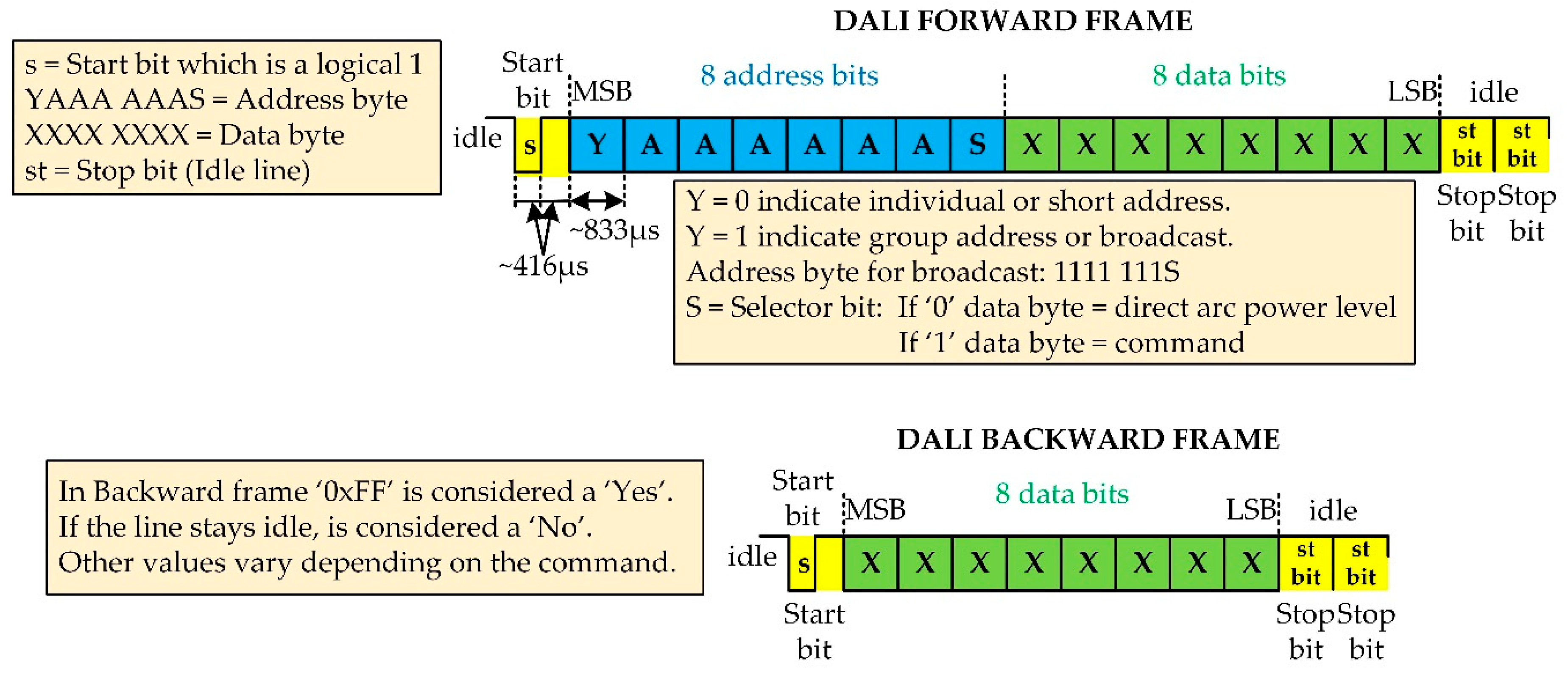
3.1. The DALI Protocol
3.2. Design Overview
3.2.1. Essential Requirements
3.2.2. Design Goals
- Low-cost and low-power embedded microcontroller-based control architecture.
- Easily reprogrammable and reconfigurable according to the user lighting needs.
- Operation system with support on hard real-time functionality.
- Integration flexibility within building control panels or with other lighting control systems.
- Ability to wirelessly connect for control and monitoring purposes using standard connection protocols (e.g., Wi-Fi, Bluetooth).
- Capable to support experimental scientific research in control of electronic ballasts and other control gears, devices and sensors.
3.2.3. Concepts and Issues
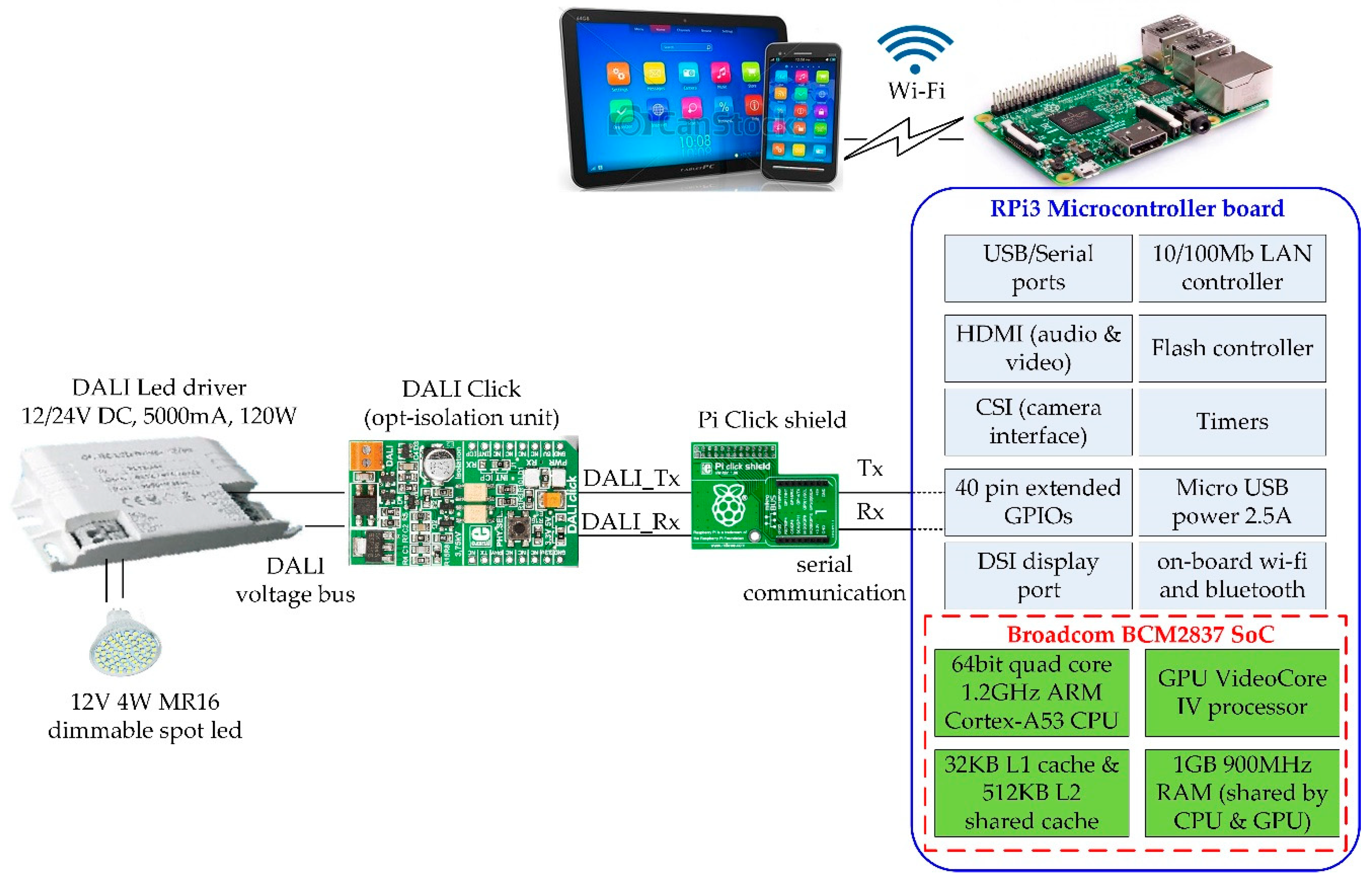
3.3. System Architecture
4. Implementation
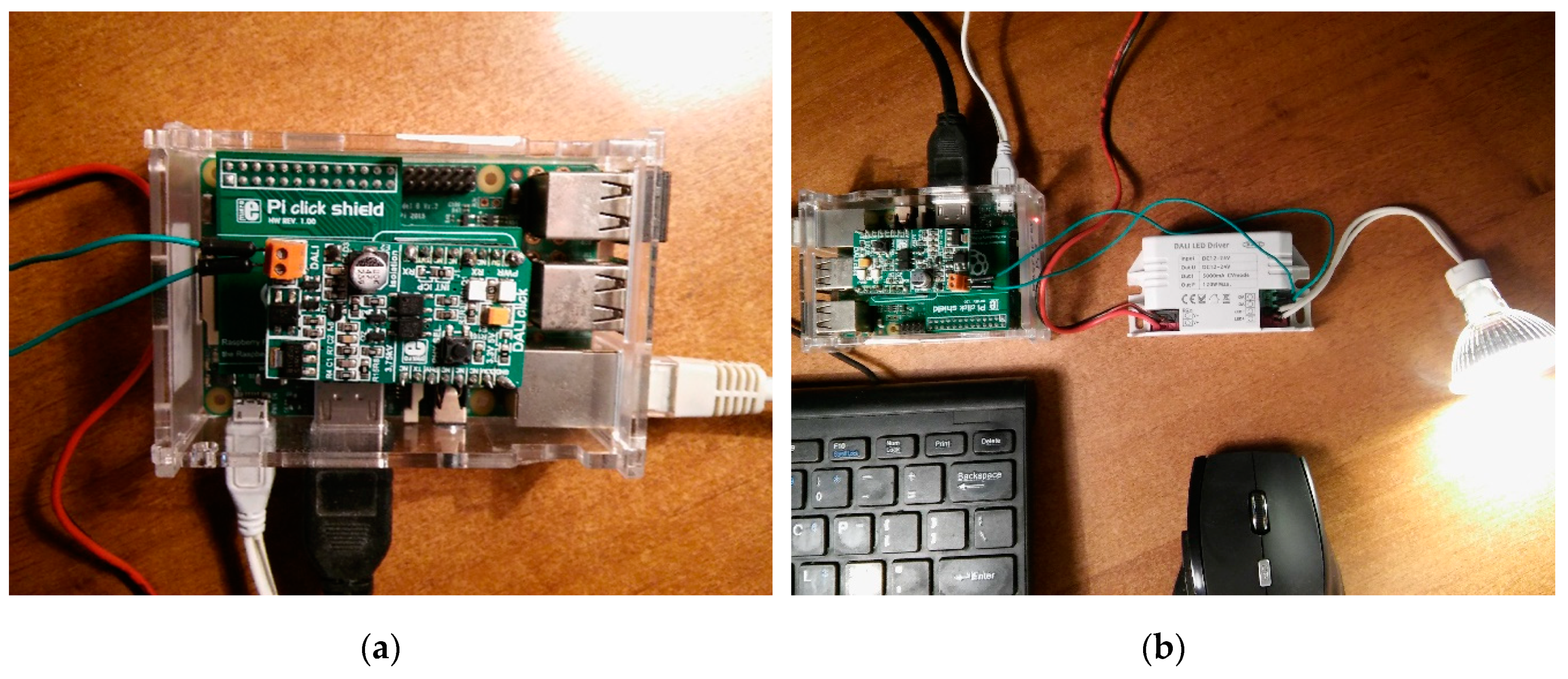
4.1. Hardware
4.1.1. Microcontroller
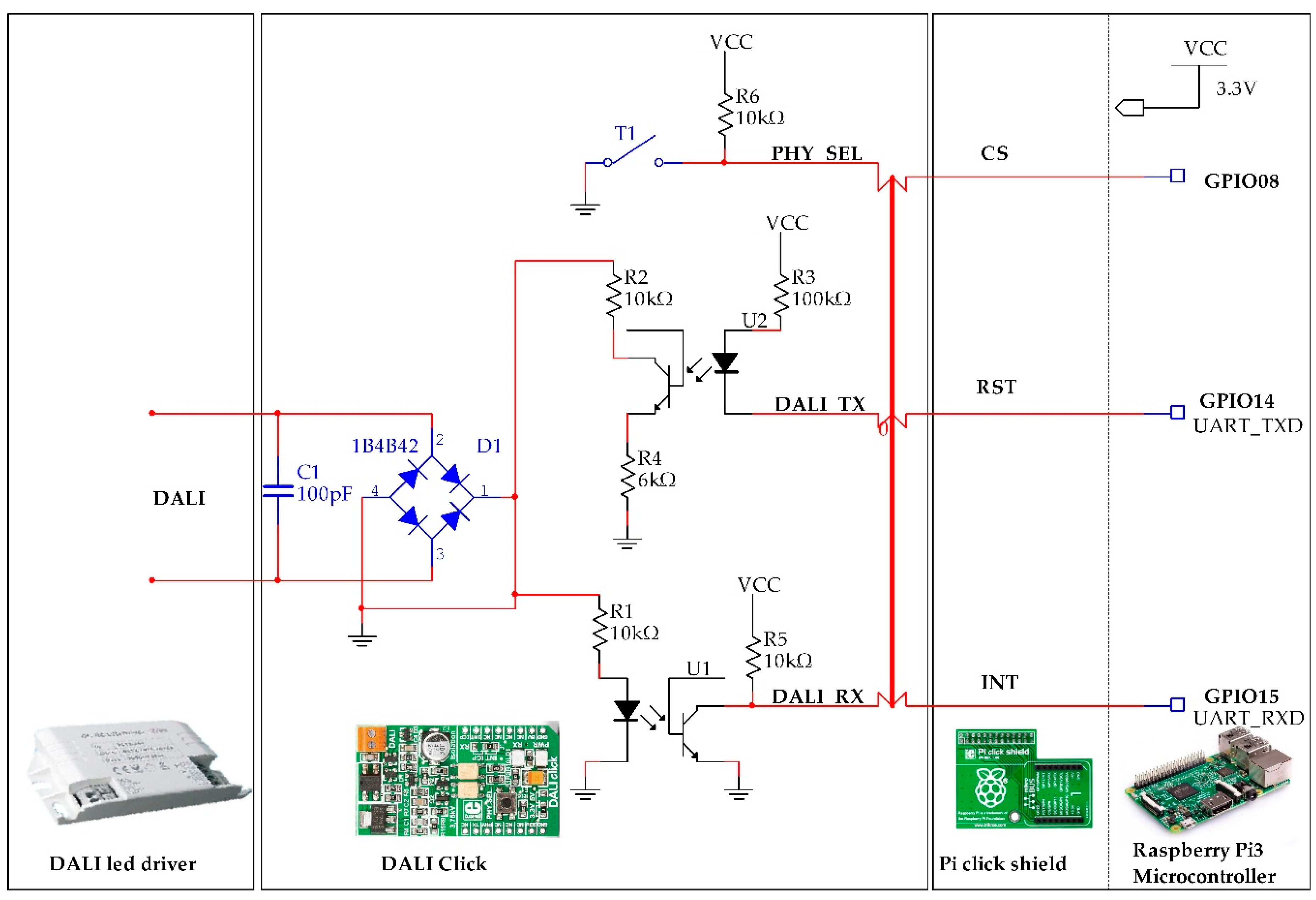
4.1.2. DALI Click Opto-Isolation Unit
4.1.3. DALI LED Driver and Spot LED Luminaire
4.2. Microcontroller and DALI Click Communication
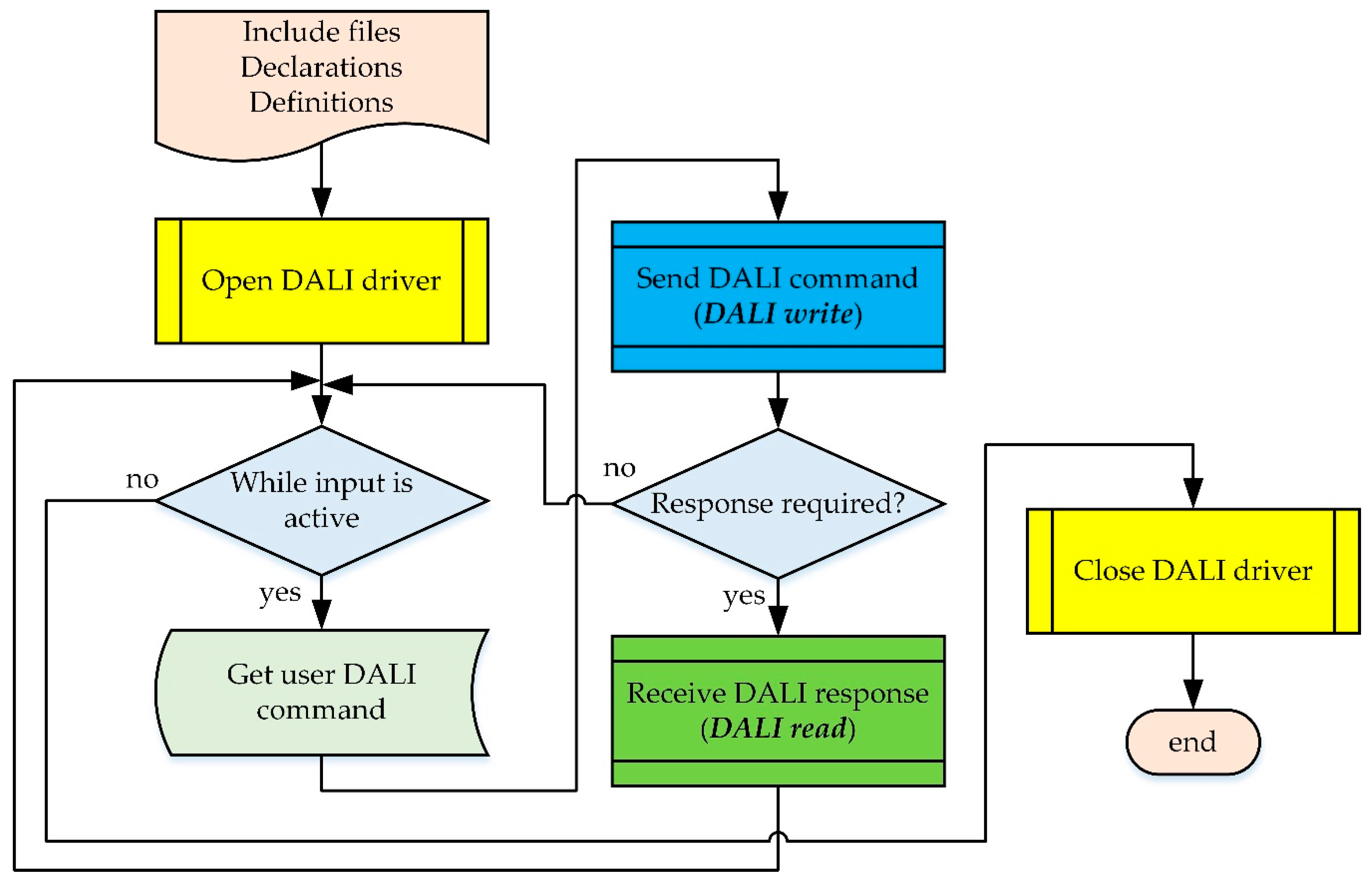
5. DALI Communication and Control Software Modules
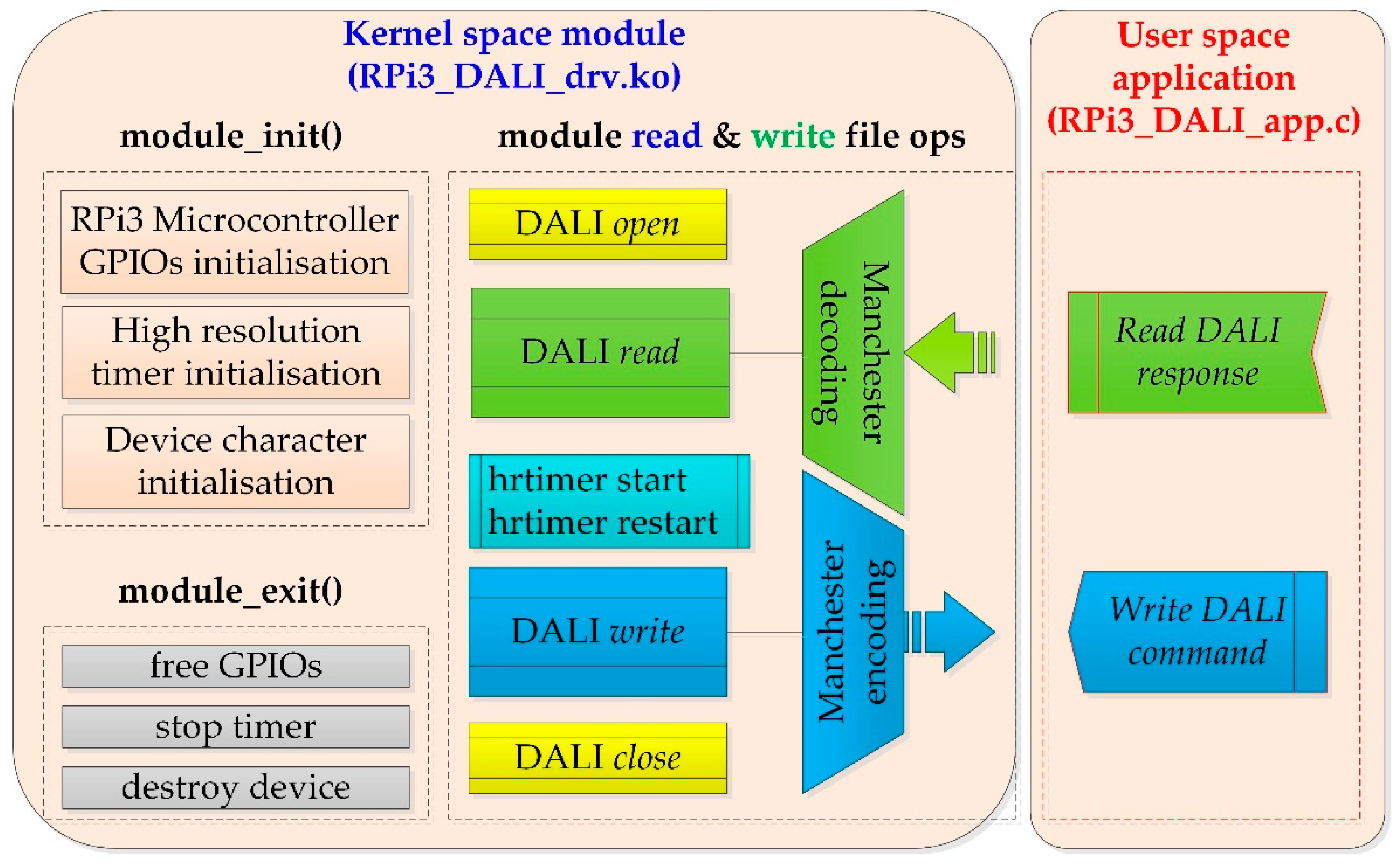
5.1. Operating System and Kernel Modules
5.2. Ballast Communication and Control Modules
| Algorithm 1. DALI read and write kernel module file operations |
| function RPi_dali_write user_buf[2] ← address & data bytes of DALI command (forward frame list) pointer_to_kernel = kmalloc(sizeof(kernel_buf), GFP_KERNEL) ← kernel allocated memory hrtimer_mode is HRTIMER_MODE_REL ← time is interpreted as relative to the current time half_bit_period_interval ← set to 416666 ns copy_from_user(DALI_command, kernel_buf) ← copy address & data bytes from user space application into kernel space memory while no_of_iterations is below or equal to 2, do dali_manchesterListAddVal(stopbit) ← send two stop bits with no phase change dali_manchesterListAddByte (databyte) ← send DALI command data byte dali_manchesterListAddByte (addressbyte) ← send DALI command address byte dali_manchesterListAddVal(startbit) ← send start bit of logical 1 hrtimer_start high_res_timer ← starts high res timer (time interval equal to half bit period) end function RPi_dali_write function RPi_dali_read user_buf[1] ← data byte from DALI command response (backward frame list) copy_to_user(DALI_response_command, user_buf) ← copy data byte from kernel space into user space application memory end function RPi_dali_read |
6. Experimental Results
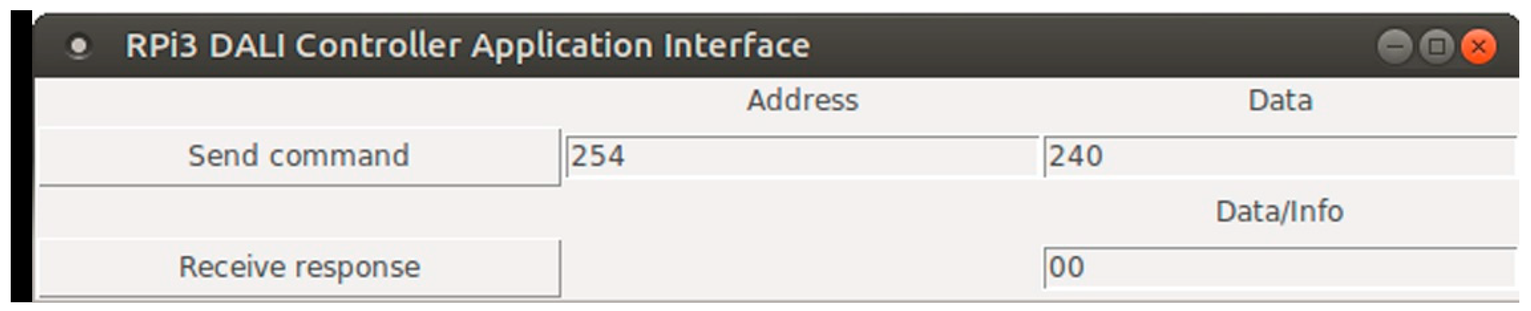
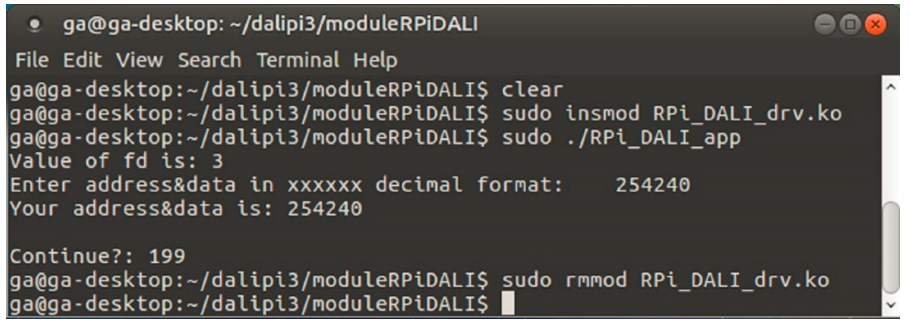
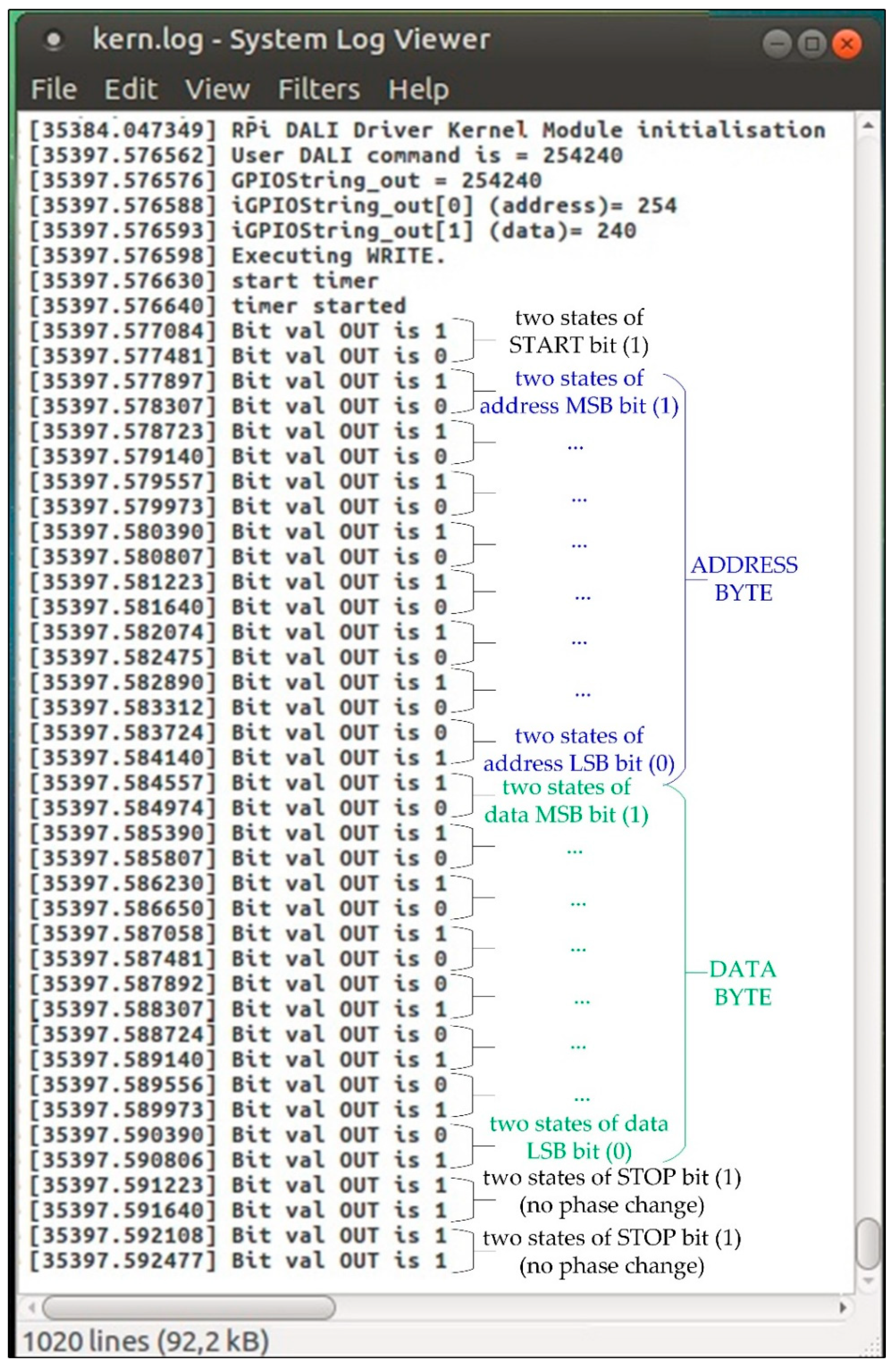
6.1. DALI Driver Module Application Experimental Results
6.1.1. DALI Kernel Driver Module Dynamic Loading
6.1.2. Experimental Application
6.2. Discussion
7. Conclusions
- Open-source, low-cost, low-power, embedded control architecture, based on Raspberry Pi3, easily reprogrammed and reconfigured for integration with other lighting automation building systems.
- Linux kernel with real-time capabilities with the real-time patch PREEMPT_RT in UBUNTU, capable to support future advanced timing control requirements.
- Dynamic loadable software control modules, based on Linux kernel modules, give flexibility to the DALI driver controller and save RAM storage space, usually limited in embedded devices.
- Capable to wirelessly connect for control and monitoring purposes using one of the standard connection protocols (e.g., Wi-Fi, Bluetooth)
Supplementary Materials
Funding
Acknowledgments
Conflicts of Interest
Appendix A
Appendix B
References
- Liang, Z.; Shen, H.-G. Survey on Building Energy Consumption Using Statistics Principle. In Proceedings of the International Conference on Digital Manufacturing & Automation, Changsha, China, 18–20 December 2010; pp. 585–589. [Google Scholar] [CrossRef]
- Yun, G.Y.; Kong, H.J.; Kim, H.; Kim, J.T. A field survey of visual comfort and lighting energy consumption in open plan offices. Energy Build. 2012, 46, 146–151. [Google Scholar] [CrossRef]
- Gonzalo, F.; Hernandez, J.A.; Moreno, B. Electrical energy consumption in buildings by means of experimental measurements: Analysis of an educational facility. In Proceedings of the International Conference on Electrical and Computing Technologies and Applications (ICECTA 2017), Ras Al Khaimah, United Arab Emirates, 21–23 November 2017. [Google Scholar] [CrossRef]
- Bakker, C.; Aries, M.; Kort, H.; Rosemann, A. Occupancy-based lighting control in open-plan office spaces: A state-of-the-art review. Build. Environ. 2017, 112, 308–321. [Google Scholar] [CrossRef]
- Li, D.H.; Cheung, K.; Wong, S.; Lam, T.N. An analysis of energy-efficient light fittings and lighting controls. Appl. Energy 2010, 87, 558–567. [Google Scholar] [CrossRef]
- Soori, P.K.; Vishwas, M. Lighting control strategy for energy efficient office lighting system design. Energy Build. 2013, 66, 329–337. [Google Scholar] [CrossRef]
- Xu, L.; Pan, Y.; Yao, Y.; Cai, D.; Huang, Z.; Linder, N. Lighting energy efficiency in offices under different control strategies. Energy Build. 2017, 138, 127–139. [Google Scholar] [CrossRef]
- Van Driel, W.; Schuld, M.; Jacobs, B.; Commissaris, F.; Van Der Eyden, J.; Hamon, B. Lumen maintenance predictions for LED packages. Microelectron. Reliab. 2016, 62, 39–44. [Google Scholar] [CrossRef]
- Nardelli, A.; Deuschle, E.; De Azevedo, L.D.; Pessoa, J.L.N.; Ghisi, E. Assessment of Light Emitting Diodes technology for general lighting: A critical review. Renewable Sustainable Energy Rev. 2017, 75, 368–379. [Google Scholar] [CrossRef]
- Lee, C.K.; Li, S.; Hui, S.Y. A Design Methodology for Smart LED Lighting Systems Powered By Weakly Regulated Renewable Power Grids. IEEE Trans. Smart Grid 2011, 2, 548–554. [Google Scholar] [CrossRef]
- Cheng, Y.-S.; Chen, J.-H.; Liu, Y.-H.; Wang, S.-C. Development of wireless RGB LED dimming control technology using smart phone. In Proceedings of the 2014 International Conference on Intelligent Green Building and Smart Grid (IGBSG 2014), Taipei, Taiwan, 23–25 April 2014. [Google Scholar] [CrossRef]
- Su, Z. Design of White Light LED Lighting Control System. In Proceedings of the International Conference on Intelligent Transportation, Big Data & Smart City (ICITBS 2018), Xiamen, China, 25–26 January 2018. [Google Scholar] [CrossRef]
- Svilainis, L. LED PWM dimming linearity investigation. Displays 2008, 29, 243–249. [Google Scholar] [CrossRef]
- Patel, M.; Mukherjee, S. Lighting Control Protocols and Standards. In Handbook of Advanced Lighting Technology; Karlicek, R., Sun, C.-C., Eds.; Springer International Publishing AG: Cham, Switzerland, 2017; pp. 559–582. [Google Scholar]
- International Electrotechnical Commission. IEC 60929:2011. AC and/or DC-supplied electronic control gear for tubular fluorescent lamps – Performance requirements. Available online: https://webstore.iec.ch/publication/3926 (accessed on 10 February 2018).
- International Electrotechnical Commission. IEC 62386-201:2015. Digital Addressable Lighting Interface – Part 201: Particular requirements for control gear – Fluorescent lamps. Available online: https://webstore.iec.ch/publication/22534 (accessed on 27 April 2018).
- Ibrahim, D. Using LEDs, LCDs and GLCDs in Microcontroller Projects, 1st ed.; John Wiley & Sons, LLC: Chichester, West Sussex, UK, 2012; ISBN 978-11-1994-070-8. [Google Scholar]
- Dean, A.G. Embedded Systems Fundamentals with ARM Cortex-M based Microcontrollers: A Practical Approach; ARM Education Media UK: Cambridge, UK, 2017; ISBN 978-19-1153-103-6. [Google Scholar]
- Bai, Y. Practical Microcontroller Engineering with ARM¬ Technology, 1st ed.; John Wiley & Sons, Inc.: Hoboken, NJ, USA, 2015; ISBN 978-11-1905-237-1. [Google Scholar]
- Jimenez, R. Microcontroller Engineer’s Notebook. 12 Experiments with PIC12F683, 1st ed.; World Class Micro Electronics: Calexico, CA, USA, 2016; ISBN 978-06-9276-419-0. [Google Scholar]
- Ferreira, J.C.; Afonso, J.A.; Monteiro, V.; Afonso, J.L. An Energy Management Platform for Public Buildings. Electronics 2018, 7, 294. [Google Scholar] [CrossRef]
- Abdalaal, R.M.; Ho, C.N.M.; Leung, C.K.; Ohin, N.I.; Rehman, S.H. A Remotely Control Dimming System for LED Lamps with Power Factor Correction. In Proceedings of the IEEE Energy Conversion Congress and Exposition (ECCE 2018), Portland, OR, USA, 23–27 September 2018; pp. 4721–4727. [Google Scholar] [CrossRef]
- Basil, E.; Sawant, S.D. IoT based traffic light control system using Raspberry Pi. In Proceedings of the International Conference on Energy, Communication, Data Analytics and Soft Computing (ICECDS 2017), Chennai, India, 1–2 August 2017; pp. 1078–1081. [Google Scholar] [CrossRef]
- Urgiles, M.V.; Arpi, P.E.; Chacon-Troya, D.P. Lighting control actuator design and development for a ZigBee network with a Web server mounted on Raspberry Pi. In Proceedings of the IEEE International Conference on Automation Science and Engineering (CASE 2015), Gothenburg, Sweden, 24–28 August 2015; pp. 714–719. [Google Scholar] [CrossRef]
- Ardito, L.; Torchiano, M. Creating and evaluating a software power model for linux single board computers. In Proceedings of the 6th International Workshop on Green and Sustainable Software, Gothenburg, Sweden, 27 May 2018; pp. 1–8. [Google Scholar] [CrossRef]
- Membrey, P.; Veitch, D.; Chang, R.K.C. Time to Measure the Pi. In Proceedings of the ACM Internet Measurement Conference (IMC 2016), Santa Monica, CA, USA, 14–16 November 2016; pp. 327–334. [Google Scholar] [CrossRef]
- The Linux Foundation. Real Time Linux. Available online: https://www.linuxfoundation.org/ (accessed on 24 March 2019).
- Han, D.-M.; Lim, J.-H. Design and implementation of smart home energy management systems based on zigbee. IEEE Trans. Consum. Electron. 2010, 56, 1417–1425. [Google Scholar] [CrossRef]
- Smith, C.B.; Parmenter, K.E. Energy Management Principles - Applications, Benefits, Savings, 2nd ed.; Elsevier: Amsterdam, Netherlands, 2015; ISBN 978-0-12-802506-2. [Google Scholar]
- Gao, Y.; Cheng, Y.; Zhang, H.; Zou, N. Dynamic illuminance measurement and control used for smart lighting with LED. Measurement. 2019, 139, 380–386. [Google Scholar] [CrossRef]
- Wang, S.; Liu, Y.; Chen, Y.-L.; Chen, J.-Y. Development of DALI-based electronic ballast with energy saving control for ultraviolet lamps. In Proceedings of the 2010 8th IEEE International Conference on Industrial Informatics, Osaka, Japan, 13–16 July 2010; pp. 214–219. [Google Scholar] [CrossRef]
- Pinto, M.F.; Soares, G.M.; Mendonça, T.R.F.; Almeida, P.S.; Braga, H.A.C. Smart modules for lighting system applications and power quality measurements. In Proceedings of the 11th IEEE/IAS International Conference on Industry Applications, Juiz de Fora, Brazil, 7–10 December 2014; pp. 1–8. [Google Scholar] [CrossRef]
- Teikari, P.; Najjar, R.P.; Malkki, H.; Knoblauch, K.; Dumortier, D.; Gronfier, C.; Cooper, H.M. An inexpensive Arduino-based LED stimulator system for vision research. J. Neurosci. Methods 2012, 211, 227–236. [Google Scholar] [CrossRef] [PubMed]
- Nodado, J.T.G.; Morales, H.C.P.; Abugan, M.A.P.; Olisea, J.L.; Aralar, A.C.; Loresco, P.J.M. Intelligent Traffic Light System Using Computer Vision with Android Monitoring and Control. In Proceedings of the TENCON 2018-2018 IEEE Region 10 Conference, Jeju, Korea, 28–31 October 2018; pp. 2461–2466. [Google Scholar] [CrossRef]
- Hernández-Ontiveros, J.; Inzunza-González, E.; García-Guerrero, E.; López-Bonilla, O.; Infante-Prieto, S.; Cardenas-Valdez, J.; Tlelo-Cuautle, E. Development and implementation of a fish counter by using an embedded system. Comput. Electron. Agric. 2018, 145, 53–62. [Google Scholar] [CrossRef]
- Cheuque, C.; Baeza, F.; Marquez, G.; Calderon, J. Towards to responsive web services for smart home LED control with Raspberry Pi. A first approach. In Proceedings of the 34th International Conference of the Chilean Computer Science Society (SCCC 2015), Santiago, Chile, 9–13 November 2015; pp. 1–4. [Google Scholar] [CrossRef]
- Yin, C.; Dadras, S.; Huang, X.; Mei, J.; Malek, H.; Cheng, Y. Energy-saving control strategy for lighting system based on multivariate extremum seeking with Newton algorithm. Energy Convers. Manage. 2017, 142, 504–522. [Google Scholar] [CrossRef]
- Adam, G.K.; Kontaxis, P.A.; Bouroussis, C.A.; Ventzas, D.E.; Topalis, F.V. Embedded computer communication and control of DALI LED drivers. In Proceedings of the Balkan Light Conference, Athens, Greece, 16–19 September 2015; pp. 125–130. [Google Scholar]
- Weng, T.; Agarwal, Y. From Buildings to Smart Buildings—Sensing and Actuation to Improve Energy Efficiency. IEEE Des. Test Comput. 2012, 29, 36–44. [Google Scholar] [CrossRef]
- Ramlee, R.A.; Othman, M.A.; Leong, M.H.; Ismail, M.M.; Ranjit, S.S.S. Smart home system using android application. In Proceedings of the International Conference of Information and Communication Technology (ICoICT 2013), Bandung, Indonesia, 20–22 March 2013; pp. 277–280. [Google Scholar] [CrossRef]
- Khunchai, S.; Thongchaisuratkrul, C. Development of Smart Home System Controlled by Android Application. In Proceedings of the 6th International Conference on Technical Education (ICTechEd6 2019), Bangkok, Thailand, 19–20 March 2019; pp. 1–4. [Google Scholar] [CrossRef]
- Leccese, F.; Cagnetti, M.; Trinca, D. A Smart City Application: A Fully Controlled Street Lighting Isle Based on Raspberry-Pi Card, a ZigBee Sensor Network and WiMAX. Sensors 2014, 14, 24408–24424. [Google Scholar] [CrossRef] [PubMed]
- Bannamas, S.; Jirapong, P. An intelligent lighting energy management system for commercial and residential buildings. In Proceedings of the IEEE Innovative Smart Grid Technologies - Asia (ISGT ASIA 2015), Bangkok, Thailand, 3–16 November 2015; pp. 1–6. [Google Scholar] [CrossRef]
- Roisin, B.; Bodart, M.; Deneyer, A.; D’Herdt, P. Lighting energy savings in offices using different control systems and their real consumption. Energy Build. 2008, 40, 514–523. [Google Scholar] [CrossRef]
- Liu, J.; Zhang, W.; Chu, X.; Liu, Y. Fuzzy logic controller for energy savings in a smart LED lighting system considering lighting comfort and daylight. Energy Build. 2016, 127, 95–104. [Google Scholar] [CrossRef]
- Domingo-Perez, F.; Gil-de-Castro, A.; Flores-Arias, J.M.; Bellido-Outeirino, F.J.; Moreno-Munoz, A. Lighting control system based on DALI and wireless sensor networks. In Proceedings of the IEEE PES Innovative Smart Grid Technologies (ISGT 2012), Washington, DC, USA, 16–20 January 2012; pp. 1–6. [Google Scholar] [CrossRef]
- Madzalan, S.N.; Hamid, H.; Hussin, M.F.; Kadir, K.A. A new automatic lighting control system using DALI for unikl BMI library. In Proceedings of the International Conference on Engineering Technology and Technopreneurship (ICE2T 2017), Kuala Lumpur, Malaysia, 18–20 September 2017; pp. 1–4. [Google Scholar] [CrossRef]
- Kudryashov, A.V.; Galishheva, E.S.; Kalinina, A.S. Lighting Control Using DALI Interface. In Proceedings of the International Conference on Industrial Engineering, Applications and Manufacturing (ICIEAM 2018), Moscow, Russia, 15–18 May 2018; pp. 1–5. [Google Scholar] [CrossRef]
- Babu, S.; Zhou, J.; Wan, M.P.; Lamano, A.S.; Sarvaiya, J.N.; Zhang, Z.; Kumar, D.K.; Gao, C.-P.; Valliappan, S.; Goh, A.; et al. Investigation of an integrated automated blinds and dimmable lighting system for tropical climate in a rotatable testbed facility. Energy Build. 2019, 183, 356–376. [Google Scholar] [CrossRef]
- Liang, T.J.; Huang, J.F.; Yadav, P.K. Design and implementation of dimmable LED control circuit with DALI protocol. In Proceedings of the IEEE International Conference on Power and Energy (PECon 2016), Melaka, Malaysia, 28–29 November 2016; pp. 121–126. [Google Scholar] [CrossRef]
- Bellido-Outeiriño, F.J.; Quiles-Latorre, F.J.; Moreno-Moreno, C.D.; Flores-Arias, J.M.; Moreno-García, I.; Ortiz-López, M. Streetlight Control System Based on Wireless Communication over DALI Protocol. Sensors 2016, 16. [Google Scholar] [CrossRef] [PubMed]
- Archana, L.; Yasin, M.; Bhagya, R. DALI based light and motor control system for movable spot luminaires. In Proceedings of the IEEE International Conference on Smart Technologies and Management for Computing, Communication, Controls, Energy and Materials (ICSTM 2017), Chennai, India, 2–4 August 2017; pp. 433–437. [Google Scholar] [CrossRef]
- Kurniawan, A. Raspberry Pi LED Blueprints - Design, build, and test LED-based projects using Raspberry Pi; Packt Publishing Ltd.: Birmingham, UK, 2015; ISBN 978-1-78217-575-9. [Google Scholar]
- Khot, S.B.; Gaikwad, M.S. Development of cloud-based Light intensity monitoring system for green house using Raspberry Pi. In Proceedings of the International Conference on Computing Communication Control and automation (ICCUBEA 2016), Pune, India, 12–13 August 2016; pp. 1–4. [Google Scholar] [CrossRef]
- Aguirre, D.; Navarrete, R.; Soto, I.; Gutierrez, S. Implementation of an emitting LED circuit in a Visible Light communications positioning system. In Proceedings of the First South American Colloquium on Visible Light Communications (SACVLC 2017), Santiago, Chile, 13 November 2017; pp. 1–4. [Google Scholar] [CrossRef]
- Perumal, V.S.A.; Baskaran, K.; Rai, S.K. Implementation of Effective and Low-Cost Building Monitoring System(BMS) Using Raspberry Pi. Energy Procedia 2017, 143, 179–185. [Google Scholar] [CrossRef]
- Kandilarov, R.Y. LED Lamp with Customizable Light Regimes for Horticulture Applications. In Proceedings of the IEEE XXVII International Scientific Conference Electronics-ET, Sozopol, Bulgaria, 13–15 September 2018; pp. 1–3. [Google Scholar] [CrossRef]
- Chen, W.; Xiong, Y.; Wang, W.; Wu, T.; Li, L.; Kang, Q.; Du, Y. Assembly of a UV-LED induced fluorescence system for rapid determination of amiloride in pharmaceutical tablet and human serum. Talanta 2019, 203, 77–82. [Google Scholar] [CrossRef] [PubMed]
- Froiz-Míguez, I.; Fernández-Caramés, T.M.; Fraga-Lamas, P.; Castedo, L. Design, Implementation and Practical Evaluation of an IoT Home Automation System for Fog Computing Applications Based on MQTT and ZigBee-WiFi Sensor Nodes. Sensors 2018, 18, 2660. [Google Scholar] [CrossRef] [PubMed]
- Sinha, A.; Sharma, S.; Goswami, P.; Verma, V.K.; Manas, M. Design of an energy efficient Iot enabled smart system based on DALI network over MQTT protocol. In Proceedings of the 3rd International Conference on Computational Intelligence & Communication Technology (CICT 2017), Ghaziabad, India, 9–10 February 2017; pp. 1–5. [Google Scholar] [CrossRef]
- International Electrotechnical Commission. IEC 62386-207:2018. Digital Addressable Lighting Interface – Part 207: Particular requirements for control gear – LED modules. Available online: https://webstore.iec.ch/publication/30618 (accessed on 12 May 2018).
- Holt, A.; Huang, C.-Y. Embedded Operating Systems: A Practical Approach, 2nd ed.; Springer: London, UK, 2018. [Google Scholar] [CrossRef]
- Raspberry Pi Foundation. Raspberry Pi3 Model B. Available online: https://www.raspberrypi.org/products/raspberry-pi-3-model-b (accessed on 5 February 2017).


| Raspberry Pi3 | BeagleBone Black | Arduino Uno R3 | |
|---|---|---|---|
| CPU | ARM Cortex-A53 (64-bit) | ARM Cortex-A8 (32-bit) | ATmega328P (8-bit AVR) |
| Memory | 1 GB LPDDR2 | 512 MB DDR3 | 32 KB flash |
| Operating System | Linux | Linux | Custom |
| GPIOs | 40 digital | 7 analog, 65 digital (3.3 V) | 6 analog, 14 digital (6 PWM) |
| Network | 10/100 Mbps Ethernet, Bluetooth, Wi-Fi | 10/100 Mbps Ethernet | via shields |
| Peripherals | 4 USB hosts, 1 micro-USB power | 1 USB host/client, 1 USB host, 4 UART | 1 USB, 1 UART |
| Power Draw | 1.34 A, 5 V | 250 mA, 5 V | 50 mA, 3.3 V |
| Average Price | 35 € | 49 € | 35 € |
| Parameter | DALI LED Driver | Parameter | Spot LED |
|---|---|---|---|
| Input voltage: | DC 12–24 V | Voltage: | 12 V |
| Output voltage: | DC 12–24 V | Colour LED: | 2700 K warm white |
| Output current: | 5000 mA | Dimmable: | yes |
| Dimming frequency: | 50 Hz | Luminous flux: | 400 lm |
| Max output power: | 120 W | Power: | 4 W |
| Min load: | 1 W | Efficiency: | 100 lm/w |
© 2019 by the author. Licensee MDPI, Basel, Switzerland. This article is an open access article distributed under the terms and conditions of the Creative Commons Attribution (CC BY) license (http://creativecommons.org/licenses/by/4.0/).
Share and Cite
Adam, G.K. DALI LED Driver Control System for Lighting Operations Based on Raspberry Pi and Kernel Modules. Electronics 2019, 8, 1021. https://doi.org/10.3390/electronics8091021
Adam GK. DALI LED Driver Control System for Lighting Operations Based on Raspberry Pi and Kernel Modules. Electronics. 2019; 8(9):1021. https://doi.org/10.3390/electronics8091021
Chicago/Turabian StyleAdam, George K. 2019. "DALI LED Driver Control System for Lighting Operations Based on Raspberry Pi and Kernel Modules" Electronics 8, no. 9: 1021. https://doi.org/10.3390/electronics8091021
APA StyleAdam, G. K. (2019). DALI LED Driver Control System for Lighting Operations Based on Raspberry Pi and Kernel Modules. Electronics, 8(9), 1021. https://doi.org/10.3390/electronics8091021