Design of a SIW Variable Phase Shifter for Beam Steering Antenna Systems


Abstract
:1. Introduction
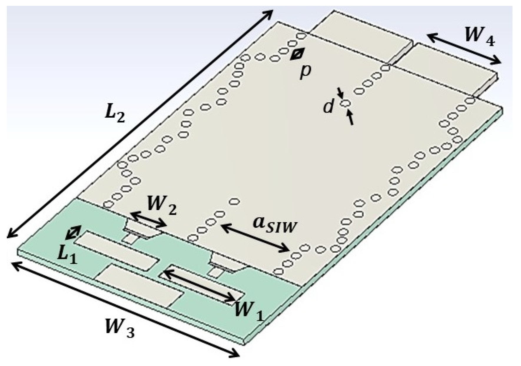
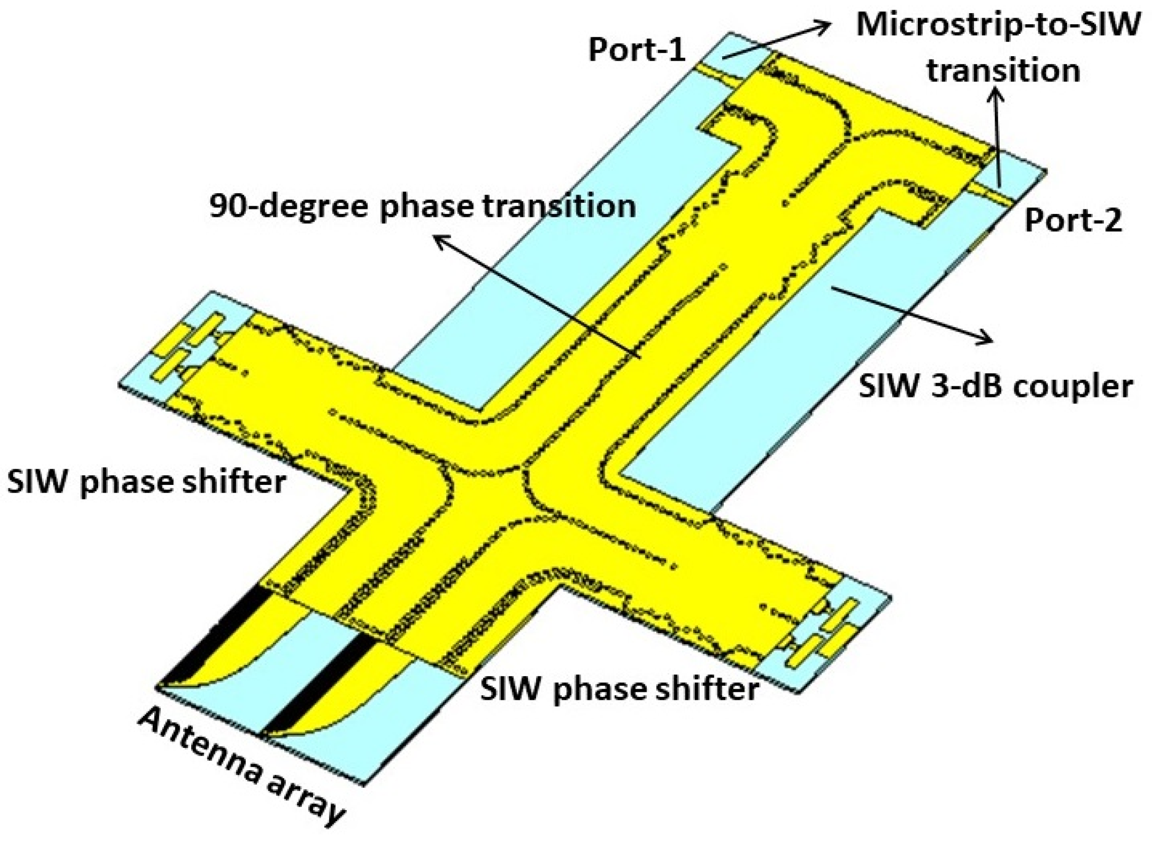
2. SIW Variable Phase Shifter
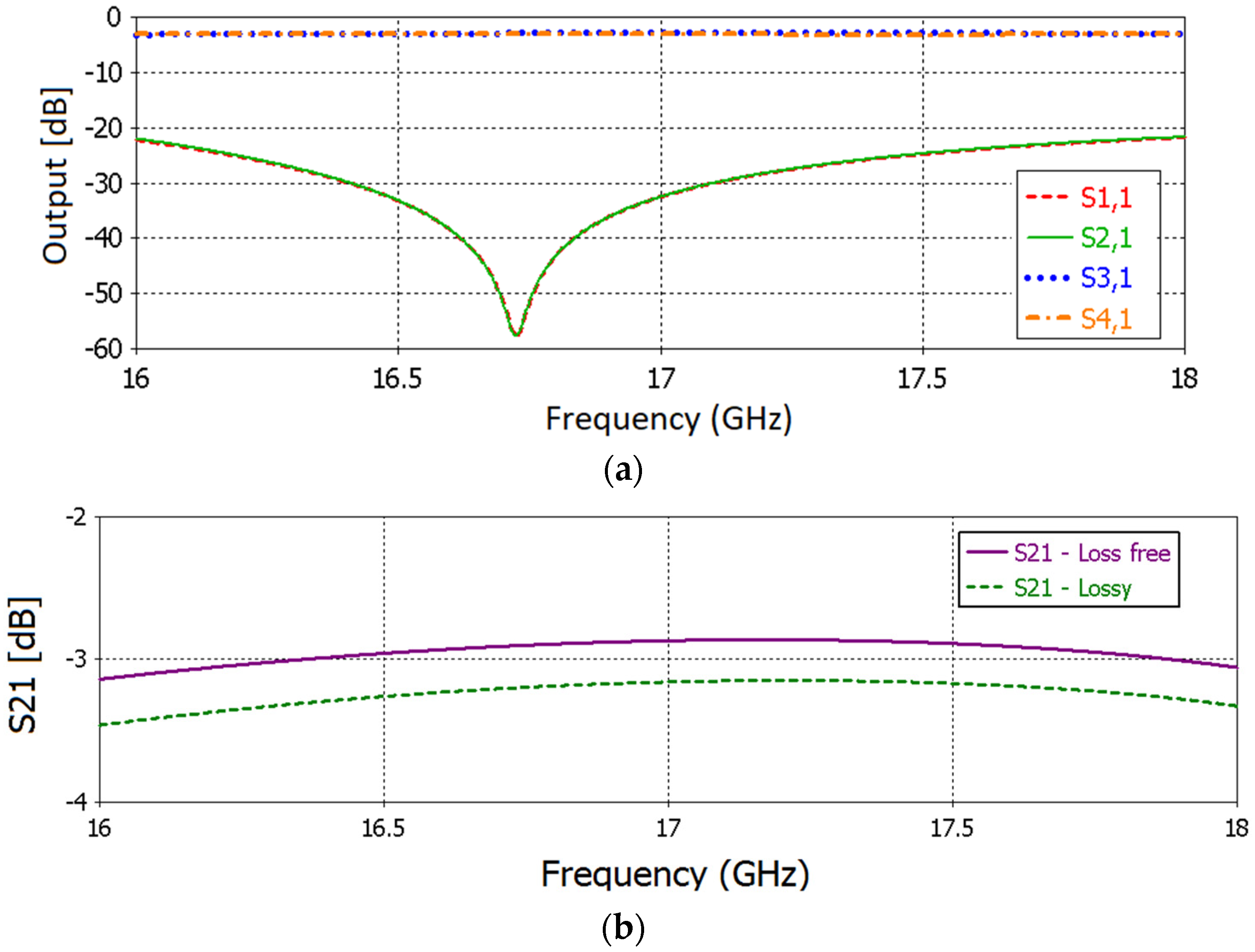
2.1. SIW 3-dB Coupler
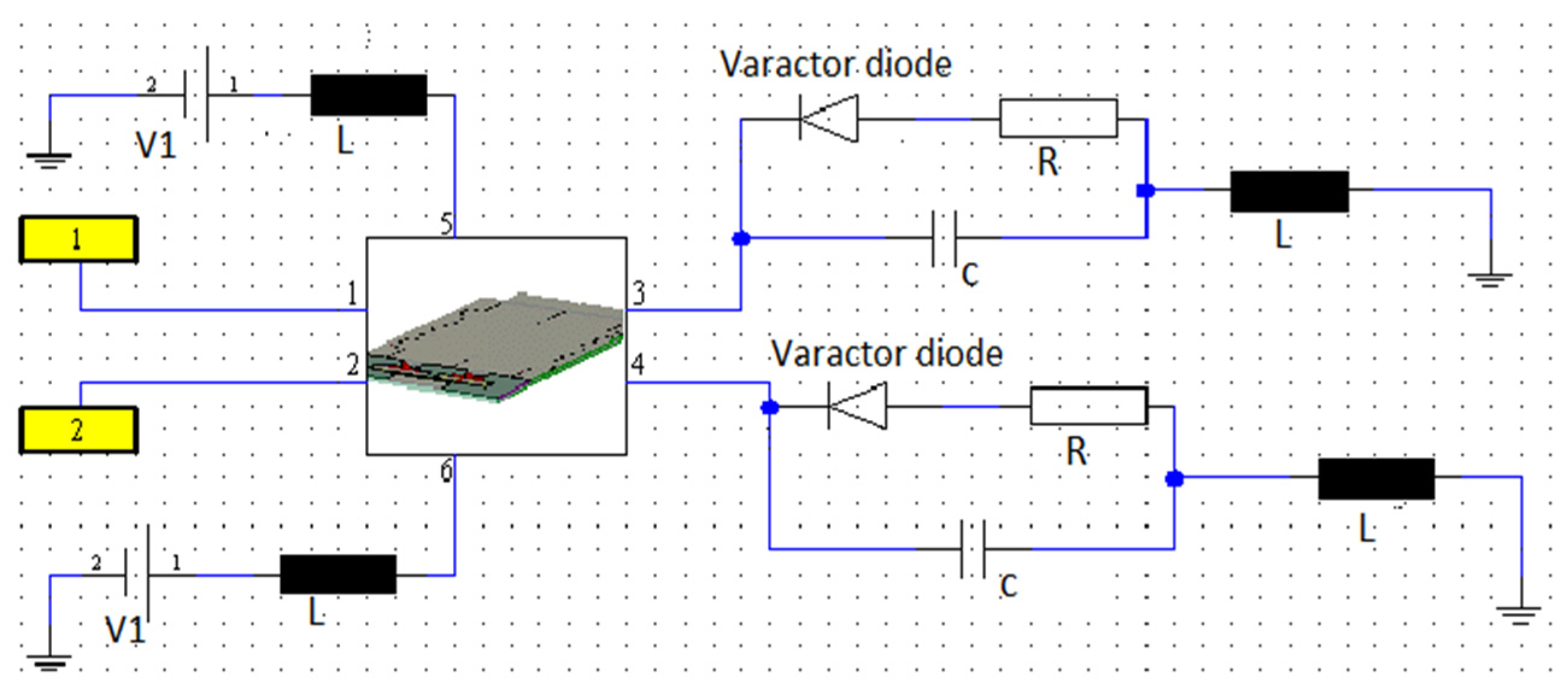
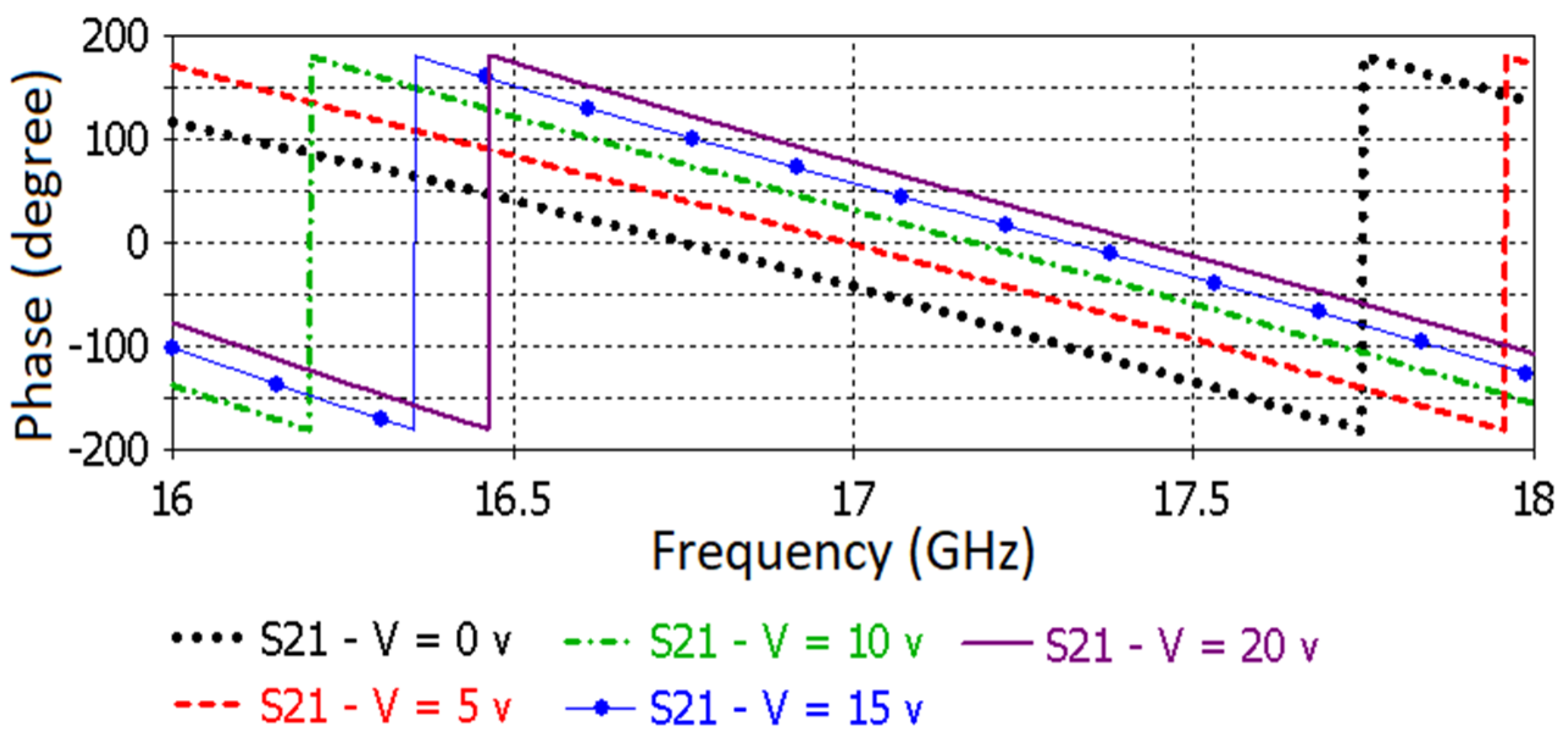
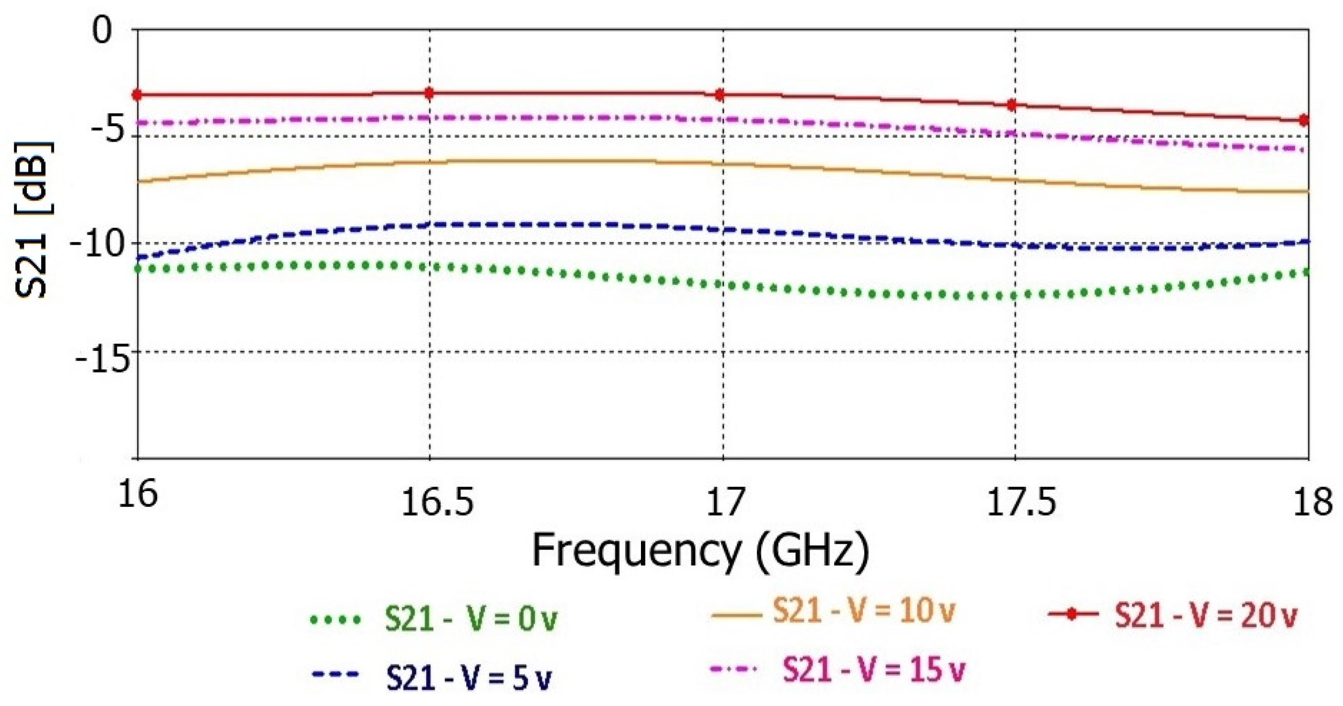
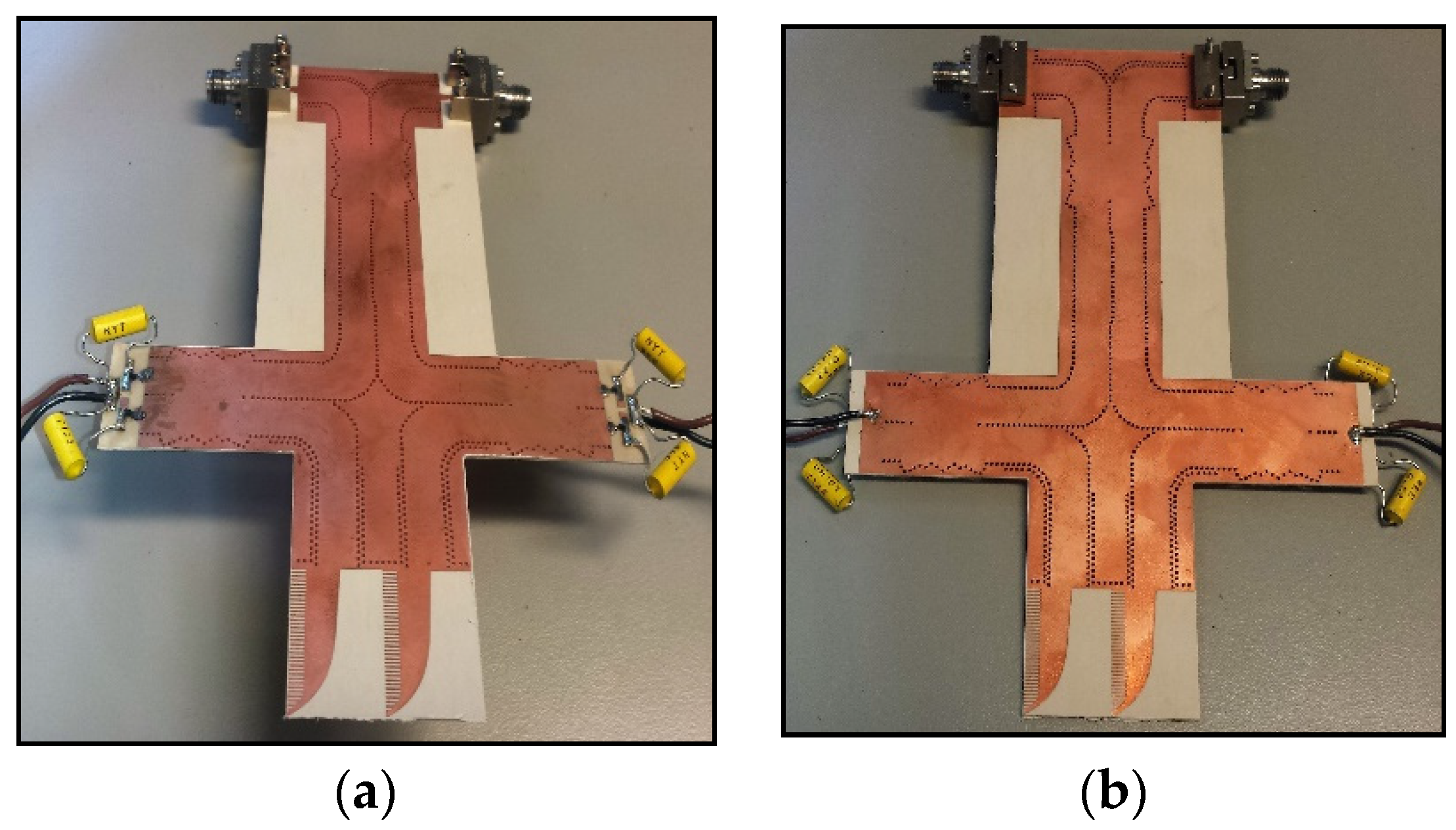
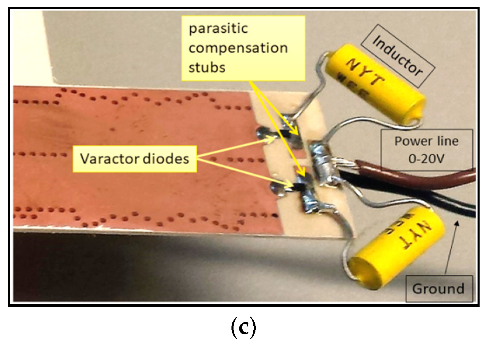
2.2. SIW Variable Phase Shifter
3. SIW Beam Steering Antenna System
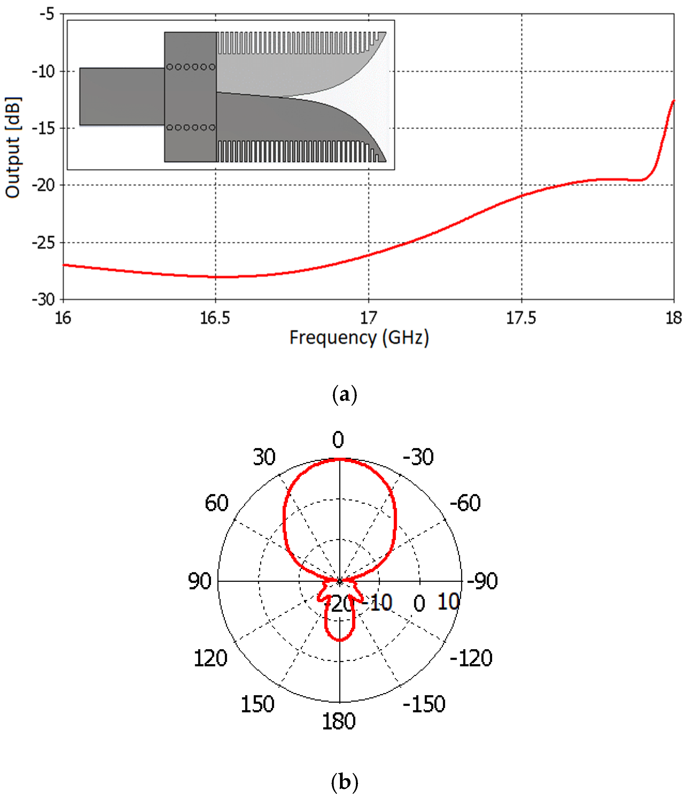
3.1. Vivaldi Antenna
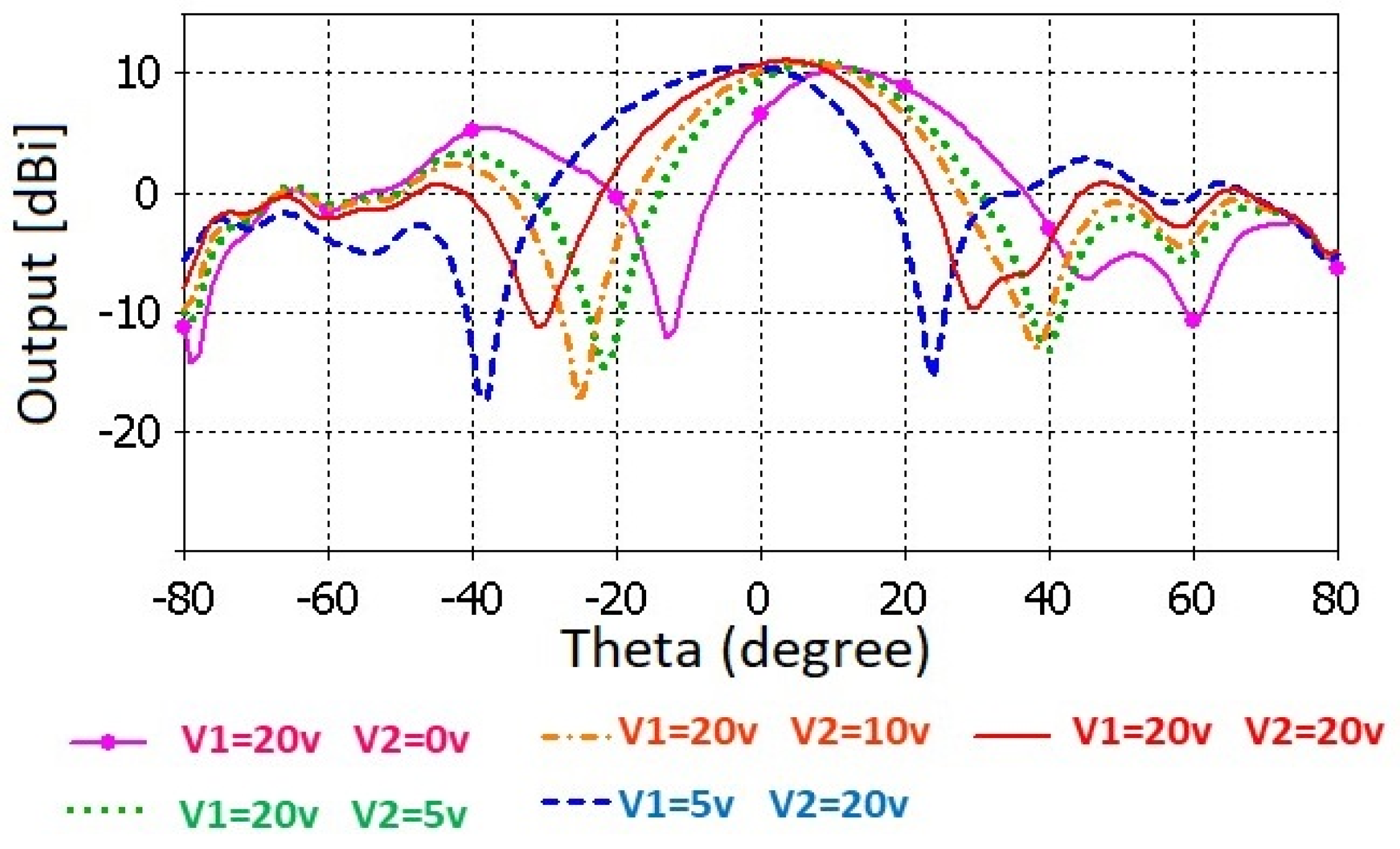
3.2. Beam Steering Antenna System
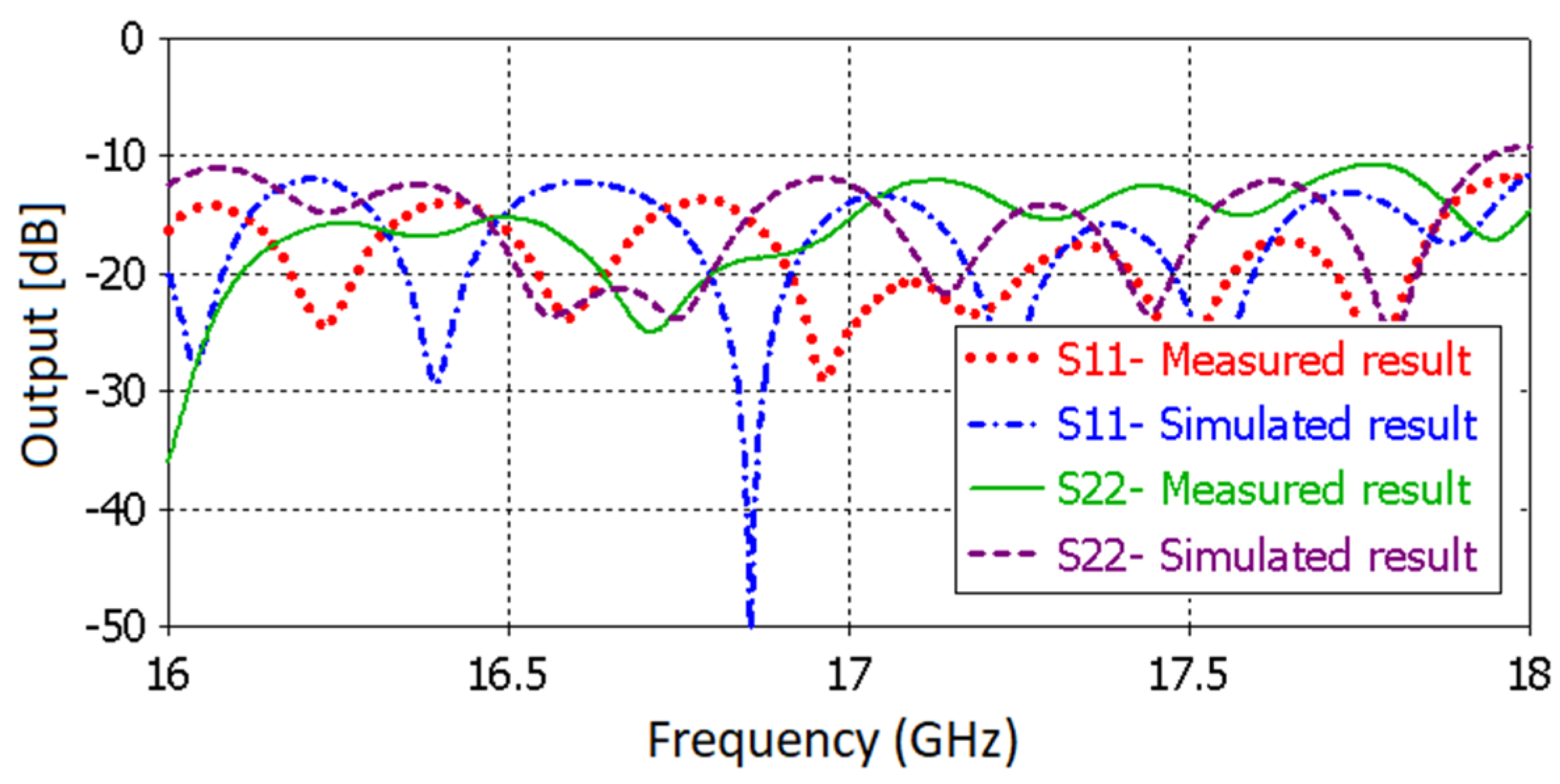
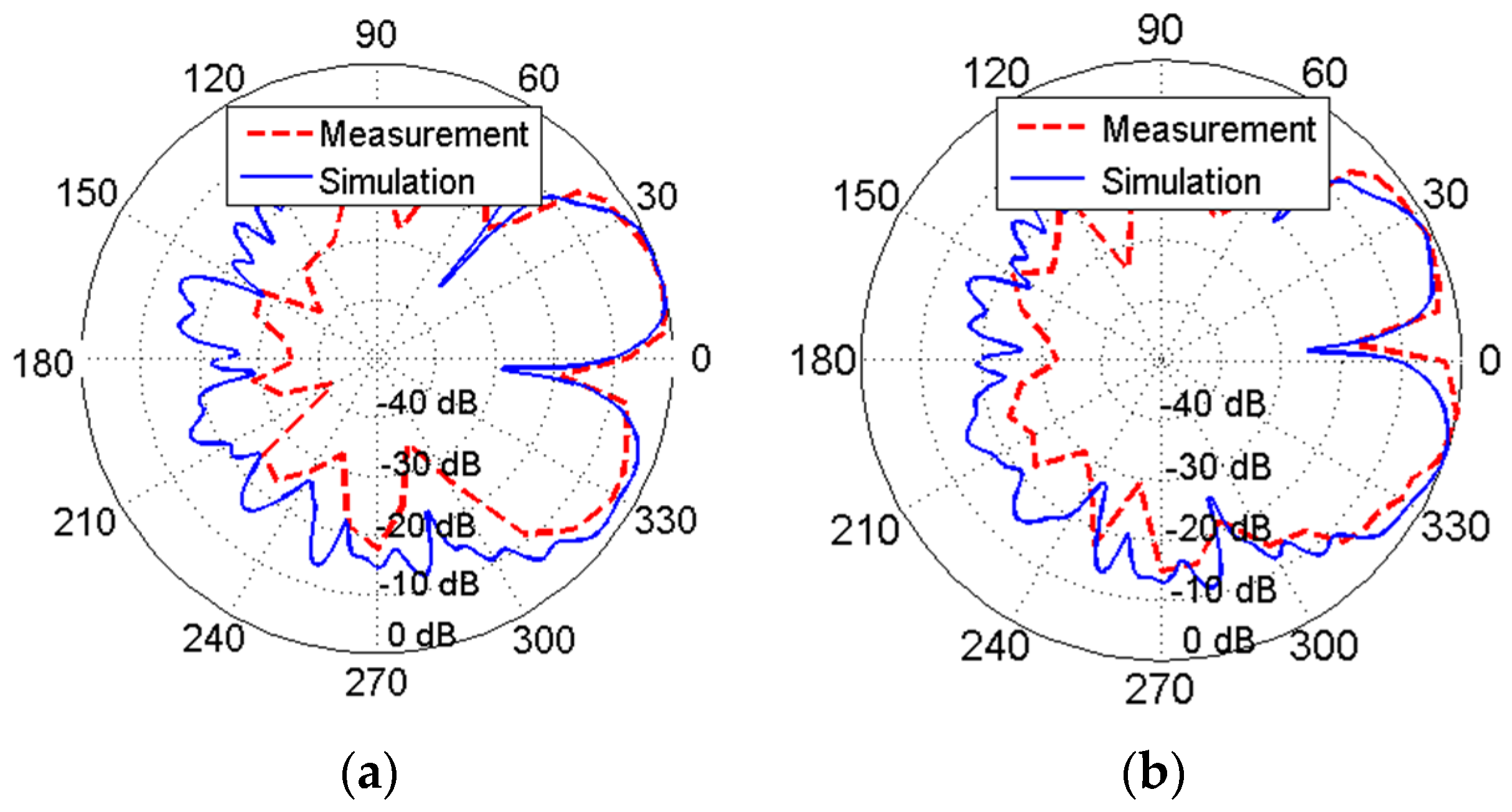
4. Experimental Results
5. Conclusions
Author Contributions
Funding
Conflicts of Interest
References
- Ding, Y.; Wu, K. Varactor-tuned substrate integrated waveguide phase shifter. In Proceedings of the 2011 IEEE MTT-S International Microwave Symposium, Baltimore, MA, USA, 5–10 June 2011; pp. 1–4. [Google Scholar]
- Errifi, H.; Baghdad, A.; Badri, A.; Sahel, A. Electronically reconfigurable beam steering array antenna using switched line phase shifter. In Proceedings of the 2017 International Conference on Wireless Networks and Mobile Communications (WINCOM), Rabat, Morocco, 1–4 November 2017; pp. 1–6. [Google Scholar]
- Djerafi, T.; Fonseca, N.J.G.; Wu, K. Planar Ku-band 4 × 4 Nolen matrix in SIW technology. IEEE Trans. Microw. Theory Tech. 2010, 58, 259–266. [Google Scholar] [CrossRef]
- Khattak, M.K.; Salman Khattak, M.; Rehman, A.; Lee, C.; Han, D.; Park, H.; Kahn, S. A flat, broadband and high gain beam-steering antenna for 5G communication. In Proceedings of the 2017 International Symposium on Antennas and Propagation (ISAP), Phuket, Thailand, 30 October–2 November 2017; pp. 1–2. [Google Scholar]
- Cao, W.; Xiang, Y.; Zhang, B.; Liu, A.; Yu, T.; Guo, D. A low-cost compact patch antenna with beam steering based on CSRR-loaded ground. IEEE Antennas Wirel. Propag. Lett. 2011, 10, 1520–1523. [Google Scholar] [CrossRef]
- Bousbia, L.; Ould-Elhassen, M.; Mabrouk, M.; Ghazel, A. New synthesis of tunable filter and phase shifter used for phased array antennas applications. In Proceedings of the 2014 International Conference on Multimedia Computing and Systems (ICMCS), Marrakech, Morocco, 14–16 April 2014; pp. 1348–1353. [Google Scholar]
- Ma, S.; Yang, G.-H.; Meng, F.-Y.; Ding, X.-M.; Zhang, K.; Fu, J.-H.; Wu, Q. Electrically tunable array antenna with beam steering from backfire to endfire based on liquid crystal miniaturized phase shifter. In Proceedings of the 2016 IEEE Conference on Electromagnetic Field Computation (CEFC), Miami, FL, USA, 13–16 November 2016; p. 1. [Google Scholar]
- Zheng, Y.; Saavedra, C.E. Full 360° vector-sum phase-shifter for microwave system applications. IEEE Trans. Circuits Syst. I Regul. Pap. 2009, 57, 752–758. [Google Scholar] [CrossRef]
- Asoodeh, A.; Mojtaba, A. A full 360° vector-sum phase shifter with very low RMS phase error over a wide bandwidth. IEEE Trans. Microw. Theory Tech. 2012, 60, 1626–1634. [Google Scholar] [CrossRef]
- Peng, Z.; Ran, L.; Li, C. A K-band portable FMCW radar with beamforming array for short-range localization and vital-Doppler targets discrimination. IEEE Trans. Microw. Theory Tech. 2017, 65, 3443–3452. [Google Scholar] [CrossRef]
- Sellal, K.; Talbi, L.; Nedil, M. Design and implementation of a controllable phase shifter using substrate integrated waveguide. IET Microw. Antennas Propag. 2012, 6, 1090–1094. [Google Scholar] [CrossRef]
- Muneer, B.; Qi, Z.; Xu, S. A broadband tunable multilayer substrate integrated waveguide phase shifter. IEEE Microw. Wirel. Compon. Lett. 2015, 25, 220–222. [Google Scholar] [CrossRef]
- Sbarra, E.; Marcaccioli, L.; Gatti, R.V.; Sorrentino, R. Ku-band analogue phase shifter in SIW technology. In Proceedings of the 2009 European Microwave Conference (EuMC), Rome, Italy, 29 September–1 October 2009; pp. 264–267. [Google Scholar]
- Formiga Mamedes, D.; Esmaeili, M.; Bornemann, J. K-band substrate integrated waveguide variable phase shifter. In Proceedings of the 2016 10th European Conference on Antennas and Propagation (EuCAP), Davos, Switzerland, 10–15 April 2016; pp. 1–4. [Google Scholar]
- Park, Z.; Lin, J. A beam-steering broadband microstrip antenna for noncontact vital sign detection. IEEE Antennas Wirel. Propag. Lett. 2011, 10, 235–238. [Google Scholar] [CrossRef]
- Ala-Laurinaho, J.; Karttunen, A.; Räisänen, A.V. A mm-wave integrated lens antenna for E-band beam steering. In Proceedings of the 2015 9th European Conference on Antennas and Propagation (EuCAP), Lisbon, Portugal, 13–17 April 2015; pp. 1–2. [Google Scholar]
- Yao, Y.-L.; Zhang, F.-S.; Zhang, F. A new approach to design circularly polarized beam-steering antenna arrays without phase shift circuits. IEEE Trans. Antennas Propagat. 2018, 66, 2354–2364. [Google Scholar] [CrossRef]
- Bartlett, C.; Salem Hesari, S.; Bornemann, J. End-fire substrate integrated waveguide beam-forming system for 5G applications. In Proceedings of the 2018 18th International Symposium on Antenna Technology and Applied Electromagnetics (ANTEM), Waterloo, ON, Canada, 19–22 August 2018; pp. 1–4. [Google Scholar]
- Nikfalazar, M.; Mehmood, A.; Sohrabi, M.; Mikolajek, M.; Wiens, A.; Maune, H.; Kohler, C.; Binder, J.R.; Jakoby, R. Steerable dielectric resonator phased-array antenna based on inkjet-printed tunable phase shifter with BST metal-insulator-metal varactors. IEEE Antennas Wirel. Propag. Lett. 2016, 15, 877–880. [Google Scholar] [CrossRef]
- Kordiboroujeni, Z.; Bornemann, J.; Sieverding, T. Mode-matching design of substrate-integrated waveguide couplers. In Proceedings of the 2012 Asia-Pacific Symposium on Electromagnetic Compatibility, Singapore, 21–24 May 2012; pp. 701–704. [Google Scholar]
- Kordiboroujeni, Z.; Bornemann, J. Design of substrate integrated waveguide components using mode-matching techniques. In Proceedings of the 2015 IEEE MTT-S International Conference on Numerical Electromagnetic and Multiphysics Modeling and Optimization (NEMO), Ottawa, ON, Canada, 11–14 August 2015; pp. 1–3. [Google Scholar]
- Kordiboroujeni, Z.; Bornemann, J. Designing the width of substrate integrated waveguide structures. IEEE Microw. Wirel. Compon. Lett. 2013, 23, 518–520. [Google Scholar] [CrossRef]
- Skyworks. SMV2201-SMV2205 Series: Surface Mount, 0402 Silicon Hyperabrupt Tuning Varactor Diodes Data Sheet. 2012. Available online: https://www.google.com/url?sa=t&rct=j&q=&esrc=s&source=books&cd=1&ved=2ahUKEwih-pbo7cXkAhVVeXAKHboTAykQFjAAegQIABAC&url=http%3A%2F%2Fwww.skyworksinc.com%2Fuploads%2Fdocuments%2F201953A.pdf&usg=AOvVaw02zMwJrKKzwrIhnLSz5yfD (accessed on 26 July 2019).
- Locke, L.S.; Bornemann, J.; Claude, S. Substrate integrated waveguide-fed tapered slot antenna with smooth performance characteristics over an ultra-wide bandwidth. ACES J. 2013, 28, 454–462. [Google Scholar]
- Salem Hesari, S.; Bornemann, J. Frequency-selective substrate integrated waveguide front-end system for tracking applications. IET Microw. Antennas Propag. 2018, 12, 1620–1624. [Google Scholar] [CrossRef]
- Balanis, C.A. Antenna Theory—Analysis and Design, 3rd ed.; Wiley: New York, NY, USA, 2005. [Google Scholar]
- Cheng, Y.; Hong, W.; Wu, K. Novel substrate integrated waveguide fixed phase shifter for 180-degree directional coupler. In Proceedings of the 2007 IEEE/MTT-S International Microwave Symposium, Honolulu, HI, USA, 3–8 June 2007; pp. 189–192. [Google Scholar]
- CST. Application Note CST STUDIO SUITE™ 2006B: Antenna Arrays. 2012. Available online: https://www.google.com/url?sa=t&rct=j&q=&esrc=s&source=web&cd=2&ved=2ahUKEwjRlru778XkAhWYHXAKHeFKDusQFjABegQIBhAC&url=https%3A%2F%2Fperso.telecom-paristech.fr%2Fbegaud%2Fintra%2FCST_ANTENNAARRAY.pdf&usg=AOvVaw0UxlbJD3SHsaJahJQ2HgwM (accessed on 26 July 2019).


| Parameter | Dimension (mm) | Parameter | Dimension (mm) |
|---|---|---|---|
| p | 1 | W1 | 6 |
| d | 0.65 | W2 | 3 |
| L1 | 1.5 | W3 | 18.6 |
| L2 | 29.46 | W4 | 6.508 |
| h | 0.508 | aSIW | 7 |
| Voltage (V) | Capacitor (pF) | Phase Shifter Angle (degree) |
|---|---|---|
| 0 | 2.10 | 0 |
| 5 | 0.67 | 45.51 |
| 10 | 0.33 | 75.92 |
| 15 | 0.26 | 106.34 |
| 20 | 0.23 | 126.02 |
| Antenna System | Number of Antenna Elements | Phase Shifter/Mode | Bandwidth (GHz) |
|---|---|---|---|
| [2] | Four | PIN diode/variable | 9.88–10.2 |
| [3] | Four | Nolan matric/fixed | 12.25–12.75 |
| [4] | Four | Butler matrix/fixed | 27–29 |
| [5] | One | CSRR/fixed | 1.98–2.05 |
| [12] | One | PIN diode/fixed | 2.8–4.8 |
| [15] | Four | 4 × 4 Butler matrix/fixed | 23–27 |
| [16] | Four | Metal-insulator-metal Varactor/variable | 7–8.4 |
| Our work | Two | Varactor diode/variable | 16–18 |
| Antenna System | Gain [dBi] | Scan Angle (degree) | Polarization |
|---|---|---|---|
| [2] | 15 | −30 to +30 | Linear |
| [3] | Not measured | Port 1/−5.3 to −15.3 Port 2/28.7 to 38.3 Port 3/6.9 to 16.2 Port 4/−27.7 to −40.7 | Linear |
| [4] | 11 | −35 to +35 | Linear |
| [5] | Not measured | −51 to +48 | Linear |
| [12] | 5.47 | Various in different frequencies. | Linear |
| [15] | 8.7–11.7 | −25 to +25 | Linear |
| [16] | 13 | −30 to +30 | Linear |
| Our work | 10.7 | −25 to +25 | Linear |
© 2019 by the authors. Licensee MDPI, Basel, Switzerland. This article is an open access article distributed under the terms and conditions of the Creative Commons Attribution (CC BY) license (http://creativecommons.org/licenses/by/4.0/).
Share and Cite
Salem Hesari, S.; Bornemann, J. Design of a SIW Variable Phase Shifter for Beam Steering Antenna Systems. Electronics 2019, 8, 1013. https://doi.org/10.3390/electronics8091013
Salem Hesari S, Bornemann J. Design of a SIW Variable Phase Shifter for Beam Steering Antenna Systems. Electronics. 2019; 8(9):1013. https://doi.org/10.3390/electronics8091013
Chicago/Turabian StyleSalem Hesari, Sara, and Jens Bornemann. 2019. "Design of a SIW Variable Phase Shifter for Beam Steering Antenna Systems" Electronics 8, no. 9: 1013. https://doi.org/10.3390/electronics8091013
APA StyleSalem Hesari, S., & Bornemann, J. (2019). Design of a SIW Variable Phase Shifter for Beam Steering Antenna Systems. Electronics, 8(9), 1013. https://doi.org/10.3390/electronics8091013