Article

A Control Strategy for a Three-Phase Grid Connected PV System under Grid Faults

Research Unit of PV, Wind and Geothermal Systems, National School of Engineering of Gabes, University of Gabes, 6029 Gabes, Tunisia
*
Author to whom correspondence should be addressed.
Electronics 2019, 8(8), 906; https://doi.org/10.3390/electronics8080906
Submission received: 14 November 2018 / Revised: 31 December 2018 / Accepted: 22 July 2019 / Published: 18 August 2019
(This article belongs to the Special Issue Grid Connected Photovoltaic Systems)

Abstract

:
This paper proposes a Low-Voltage Ride-Through control strategy for a three-phase grid-connected photovoltaic (PV) system. At two stages, the topology is considered for the grid-tied system fed by a photovoltaic generator with a boost converter followed by a three-phase voltage source inverter. A flexible control strategy is built for the proposed system. It accomplishes the PV converter operations under the normal operating mode and under grid faults (symmetrical and asymmetrical grid voltage sag). The boost converter is controlled via an incremental conductance maximum power point tracking technique to maximize the PV generator power extraction. In the case of voltage sag, the implemented control strategy provides a switch between MPPT mode and non-MPPT mode to ensure the protection of the power converters. Theoretical modeling and simulation studies were performed, and significant results are extracted and presented to prove the effectiveness of the proposed control algorithm.

1. Introduction

In recent years, the world is approaching an energy crisis and environmental issues such as global warming and pollution, which direct research interest toward the improvement of renewable energy, such as photovoltaic systems, wind turbine, biomass energy, fuel cells, etc.
The generation of photovoltaic renewable energy is the most attractive because of its high availability, the simplicity of the topology, and low cost compared to other resources of renewable energy. As a result, the number of grid-connected photovoltaic (PV) systems is increasing significantly, and studies to ameliorate their reliability and performance are progressing [1,2,3,4,5,6]. However, the high penetration level of distributed generation systems can have a negative influence on the global reliability and stability of the grid, especially under grid fault conditions such as voltage sags and with the use of more and more high-tech devices with good performance and high effectiveness but also with more sensitivity to their electric supply sources [7]. In fact, the utilization of similar sensitive devices makes voltage sags become a serious and grave problem. Figure 1 shows many kinds of devices sensitive to voltage variation and widely used in the industry.
In the case that such sensitive devices are used in a key process, then the interruption of the devices resulting from the voltage sag may lead to the shutdown of the whole industry; therefore, resulting in an enormous loss that may include environmental problems or even personal injury [8].
In this regard, the grid codes of the countries with large-scale integration of distributed generation systems have determined the profile of the faults that these systems should resist, and how it should react under similar situations.
In accordance with these requirements, the distributed generation sources must remain connected to the grid during voltage dips, pursuing a predetermined time/sag-depth profile before it disconnects, which is recognized as low-voltage ride-through (LVRT).
Furthermore, grid codes demand the injection of reactive power to maintain the grid voltage and to diminish the probability of voltage collapse [7,8,9]. As a result, it is expected that the increasing number of distributed generation systems will result in new requirements in grid codes. In the future, grid codes could require the injection of reactive power from the distributed photovoltaic systems to completely exploit the reactive power provisions [8,9,10].
Based on these requirements, several LVRT strategies have been suggested to ameliorate the performances of distributed generation systems during voltage sags [11,12,13,14,15,16,17,18,19,20,21]. The symmetric sequence is used in most of the previous works because of the fact that it obtains particular control objectives like voltage support, peak current limitation, and the mitigation of reactive and active power oscillations.
The main problem associated with voltage sags is the increase of the voltage of the DC-link and which may cause the tripping of the inverter. To solve this problem and maintain the stable connection of the three-phase grid-tied PV system as long as possible under grid faults, different control strategies are developed. For example, positive sequence control, unity power factor control, constant reactive power control, and constant active power control [22,23,24,25,26,27,28]. These studies used several topologies of power converters for photovoltaic systems like single-stage [29,30] or two-stage [30,31], with or without a transformer [32]. However, the majority of these works discuss only the control of the inverter and omit the study of the MPPT algorithm. In addition, the majority of papers discuss the impact of the proposed control strategy on only symmetrical voltage sags and don’t discuss the impact related to asymmetrical voltage sag.
Hence, this paper presents a flexible control strategy for a three-phase grid-tied PV system which accomplishes the PV converter operations under normal operating mode and under symmetrical and asymmetrical grid voltage sag. The boost converter is controlled via an incremental conductance maximum power point tracking method in order to maximize the extracted PV power. In the case of low grid voltage or voltage sag, the control of the MPPT will be deactivated if necessary and an additional DC-bus voltage regulator incorporated into the control of the boost will command the boost to reduce the PV power to the target value injected by the inverter at the common point of interconnection.
This paper is organized as follows: The first section is the introduction. The second section describes the system configuration. The third section details the proposed control approach and the last section presents and discusses the simulation results.

2. System Configuration

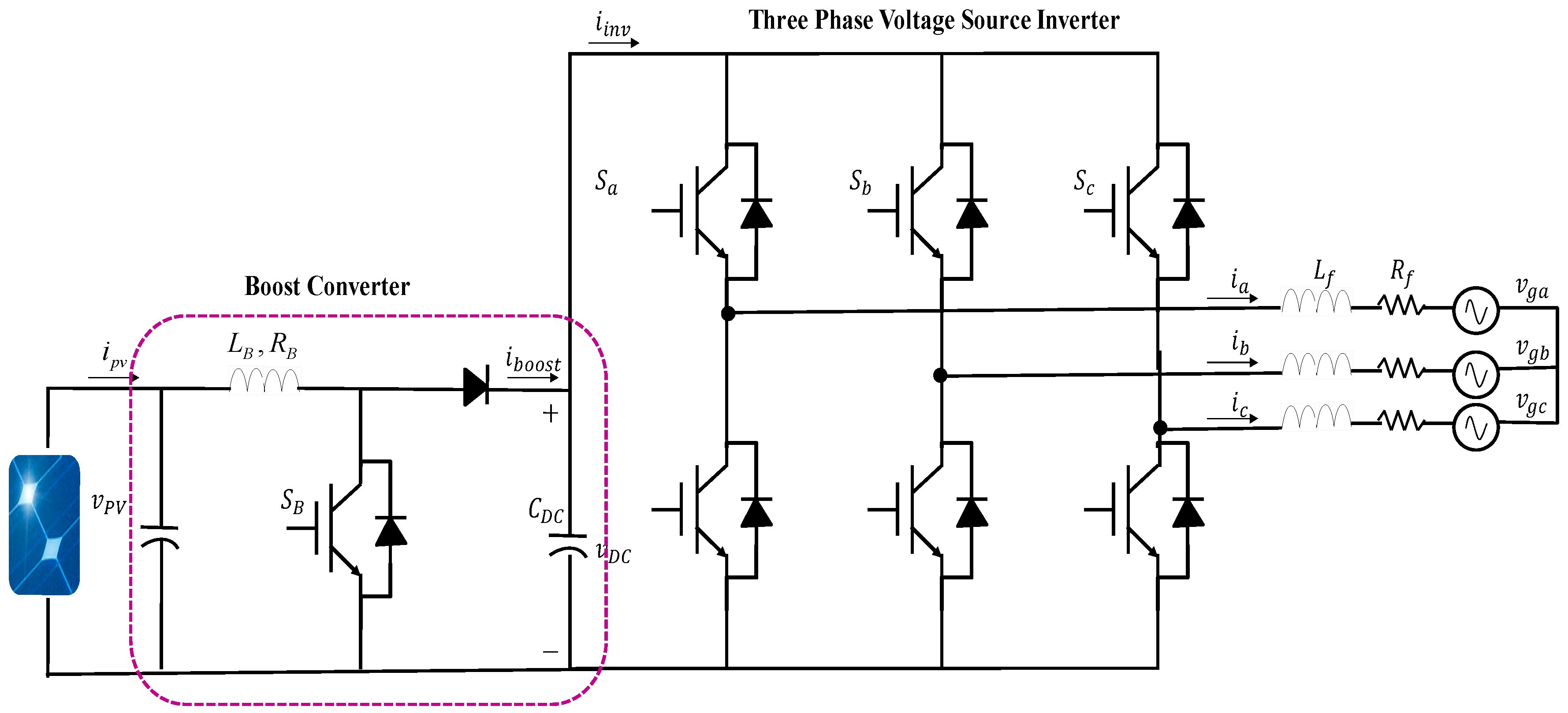
The configuration of the investigated system is shown in Figure 2 for the grid-tied photovoltaic system; a two stages system is suggested. The first stage is a DC-DC boost converter serving to control the power provided by the photovoltaic generator, i.e., the extraction of maximum power in the normal case or MPPT mode and for the control in case of a voltage sag. The second stage is a two-level three-phase Voltage Source Converter (VSC). The output of the boost converter is connected to the DC link of the VSC. The three-phase VSC is composed of three Insulated Gate Bipolar Transistor (IGBT) legs. The output terminals of VSC are connected to R, L filter and the other end of the filter are connected to the common point of interconnection.

3. Control Approach

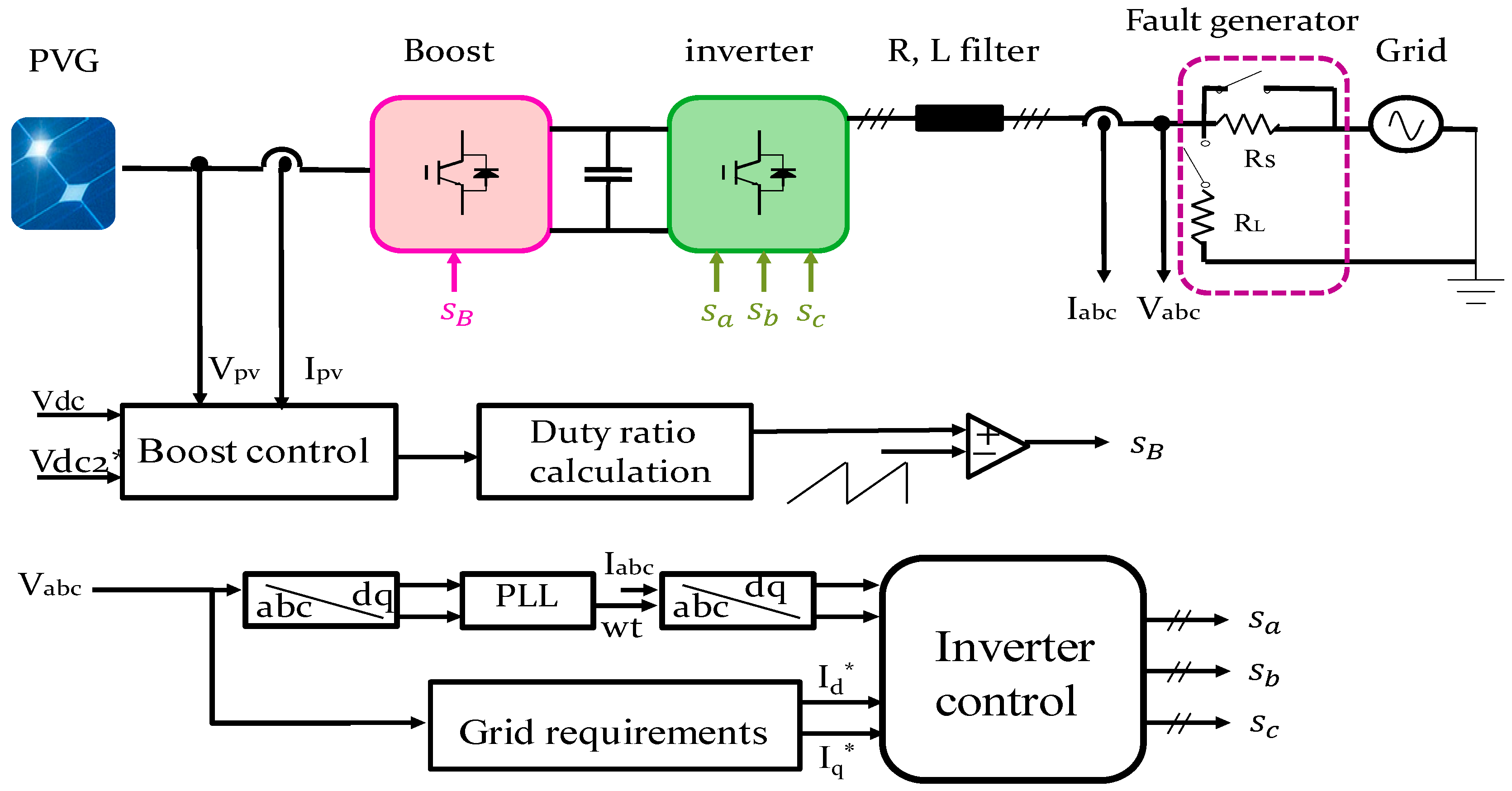
The control diagram of the PV connected system used in this paper is presented in Figure 3. The control of the system can be divided into two main parts; the boost converter control and the grid-tied inverter control. For the boost control, two modes are proposed; mode MPPT and mode non-MPPT. The first stage of the proposed system is used for boosting the PV voltage to the desired value and to set the operating point of the PV generator to the maximum power operating point. The second stage is used to convert the DC power extracted from the PV generator to an acone. The control unit is composed of a voltage, current controllers, a MPPT control, and voltage sag detection. It is required that the photovoltaic generator must stay connected to the grid and the inverter should inject reactive power when voltage sag is occurring. Hence, the strategy followed in the control must be ameliorated to avoid the waste of PV power generated and mainly to stabilize the grid-tied PV system.
The proposed control system is programmed to switch from normal operating mode (absence of voltage sag) to grid faulty operating mode in the case that voltage sag is detected. The inverter injects reactive power based on the voltage sag level and duration. Meanwhile, the photovoltaic generator should switch to the non--MPPT operating mode to protect the inverter against overcurrent.

3.1. MPPT Mode

The incremental conductance (Inc-Cond) approach is applied in this paper for maximum power point tracking. This algorithm is shown in the flowchart in Figure 4.

3.2. LVRT Control System and VSC Control

In a normal case, if no voltage dip occurs, the photovoltaic system operates in MPPT mode. However, if a voltage dip happens then the PV system continues working on MPPT mode if the power extracted from the PV generator is less than the allowed maximum grid power. If it is not the case and the present power of the PV generator exceeds the allowed maximum grid feeding power then the procedure of extracting the maximum power from the PV generator must be stopped. Then, we must pass to non-MPPT mode.

3.2.1. Generation of PV Voltage Reference (Mode: Non-MPPT)

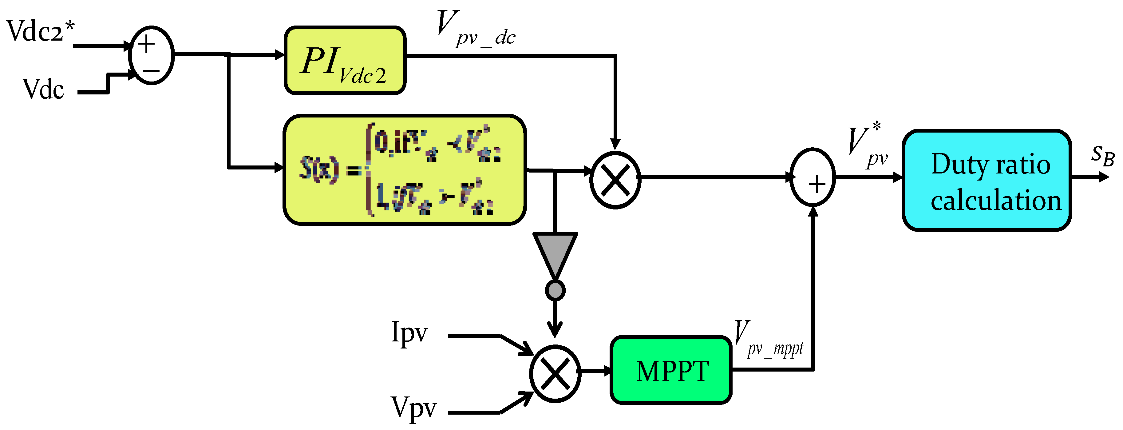
If there is no voltage dip, the voltage of the DC-bus is adjusted to its reference which is 660 V by a PI (proportional integrator) regulator. Therefore, the Vpv_dc will be equal to zero and the reference of the PV voltage is determined by the MPPT controller. Otherwise, if the voltage drops then the voltage of the DC-bus will increase until it achieves the upper limit; fixed to 680 V in this paper. Then, the output of the PIvdc2 is no more equal to zero and the PV voltage reference is regulated so that the voltage of the DC-bus stays equal to 660 V and stop increasing as shown in Figure 5. Once the grid voltage sag is removed, the grid feeding power increases and the DC-bus voltage decreases. As a result, the PIvdc2 raises the DC-bus voltage control.
As shown in Figure 5, the reference of the PV voltage can be presented as:
V*pv = Vpv_mppt + Vpv_dc
If a voltage sag occurs, then the converter injects reactive current to support the grid voltage according to the grid codes. Figure 6 shows the reactive current requirement according to the corresponding voltage V and the rated current I.

3.2.2. Control of the Voltage Source Inverter (VSI)

The flowchart of the proposed control system is shown in Figure 7. In fact, the control of the grid-side inverter can be divided into two parts; the outer loop or control of the DC-bus voltage and the inner loop or control of the current and calculation of the voltage references. Figure 8 shows the principle of the grid-side inverter control.
And to insure the feed-forward control, the voltage references are:
{ v d = v d + R i d + L d i d d t w L i q v q = v q + R i q + L d i q d t + w L i d

4. Simulation Results

The simulated system specifications are given in Table 1.
In normal conditions, the grid-tied PV system is operating in MPPT mode to extract and deliver the maximum power to the grid. The simulated waveforms are shown in Figure 9, Figure 10, Figure 11, Figure 12, Figure 13, Figure 14, Figure 15, Figure 16, Figure 17, Figure 18, Figure 19, Figure 20, Figure 21, Figure 22, Figure 23, Figure 24, Figure 25, Figure 26, Figure 27 and Figure 28. The simulation results are obtained under constant temperature (25 °C) and irradiance (1000 W/m2). The parameters of the system are presented in Table 1. The simulated PV generator is a Sun Power SPR-305-WHT (San Jose, CA, USA).
  • Symetrial voltage sag
  • Asymmetrical voltage sag: type B (phase a)
  • Asymmetrical voltage sag: type B (phase b)
Based on Figure 10, Figure 18 and Figure 24, the voltage of the DC-link, in the case of symmetrical and asymmetrical voltage sag type B or C, follows instantaneously its reference which is 660 V until 0.4 s when the voltage sag occurs. Hence, the DC-link voltage starts to increase and, due to an additional PI regulator, this voltage is adjusted to stay at 680 V.
Figure 15 and Figure 16 show the grid phase and the frequency calculated by the phase locked loop (PLL). They are maintained at their rated values which are 314 rd/s and 50 Hz, respectively. They prove to have highest performances of the several control loops designed.
Once the voltage sag occurs, at t = 0.4 s, the reactive and active powers change from their rated values. The active power decreases from 99 kW to 58 kW while the reactive power increases from zero to 40 kVAR in order to support and withstand the voltage sag. The injection of the reactive power is clear in Figure 12, Figure 13 and Figure 14. In these figures, before the voltage sag (before t = 0.4 s), the current and the voltage are in phase but this is no longer the case between t = 0.4 s and t = 0.6 s, the period of the voltage sag. This aspect is also illustrated in Figure 20, Figure 21 and Figure 22 for asymmetrical voltage sag (phase a) and in Figure 26, Figure 27 and Figure 28 for asymmetrical voltage sag (phase b). These figures show that the current and the voltage are no longer in phase with each other which ensures the results shown in Figure 17 and Figure 23 and the injection of reactive power. Once the voltage sag disappears, the injection of reactive power is terminated and the grid voltage and current are in phase once again.
In fact, when the grid voltage decreased from 326 V to 228 V (30%), the inverter output current normally started to increase until it achieves its saturation value. After that, the power injected into the grid becomes lower than the power produced by the PV generator. The difference between the power produced and injected will be accumulated in the capacitor of the DC-link. As a result, and due to the surplus of energy, the voltage of the DC-link increases normally to a high value that can destroy the capacitor. Generally, the voltage of the DC-link exceeds the internal protection so that the protection of the system intervenes to disconnect the inverter from the grid.
To protect the inverter in case of a grid voltage sag, two different references of the DC-bus voltage are introduced in this work Vdc1* (660 V) and Vdc2* (680 V). The voltage of the DC-link is controlled to be equal to its reference Vdc1* in normal operating mode, while this same voltage is adjusted to be equal to Vdc2* in faulty operating mode. Figure 10 shows this aspect clearly. This figure shows that before 0.4 s which represents the normal mode (absence of voltage sag) the DC-link voltage follows its reference 660 V. After 0.4 s (in the case of voltage sag), Vdc starts to increase but due to the added regulator PI_lvrt, this voltage is adjusted to be equal to 680 V and stops increasing to protect the inverter from being destroyed.

5. Conclusions

In this work, a control strategy approach is proposed and developed around a two-stage grid-tied PV system operating under different operational modes (normal conditions, symmetrical, and asymmetrical voltage sag). The simulation results show that during normal conditions, the proposed command ensures the extraction of the maximum power from the PV generator and satisfying regulation of the DC-link voltage and for the most part the output inverter current. Furthermore, the injection of energy into the grid is ensured at a unity power factor. In grid faulty operation mode, in order to stabilize the whole system, the inverter decreased the active power and delivered a reactive power greater than zero. It is important to notice that the reactive and active power change with the voltage sag levels. Moreover, in faulty mode, the proposed control strategy provides ride-through capability during the grid voltage sags and ensures grid sinusoidal current at the common point of interconnection.
The effectiveness and flexibility of the proposed power control strategy have been demonstrated mainly under grid faults. In the future, it is intended that future PV converters will have some auxiliary and intelligent service like reactive power compensation, avoidance of PV generation loss due to anti-islanding shutdown, and mitigation of voltage variation. These advanced controls represent the key to ameliorate the PV systems and reduce the total cost of energy.

Author Contributions

In this paper, E.M.K. contributes to the design and simulation of the LVRT control strategy of the grid connected PV system and the writing of the manuscript. D.E.C. contributes to the design of the LVRT control strategy and reviewing of the manuscript. L.S. provides overall supervision and guidance to finalize the work. All the authors read and approved the manuscript.

Funding

This research received no external funding.

Conflicts of Interest

The authors declare no conflict of interest.

References

  1. Ahmed, T.; Soon, T.K.; Mekhilef, S.A. Single Phase Doubly Grounded Semi-Z-Source Inverter for Photovoltaic (PV) Systems with Maximum Power Point Tracking (MPPT). Energies 2014, 7, 3618–3641. [Google Scholar] [CrossRef]
  2. Brando, G.; Dannier, A.; Del Pizzo, A.; Spina, I. Control and Modulation Techniques for a Centralized PV Generation System Grid Connected via an Interleaved Inverter. App. Sci. 2016, 6, 261. [Google Scholar] [CrossRef]
  3. Che, Y.; Li, W.; Li, X.; Zhou, J.; Li, S.; Xi, X. An Improved Coordinated Control Strategy for PV System Grid Integration with VSC-MVDC Technology. Energies 2017, 10, 1670. [Google Scholar] [CrossRef]
  4. Dou, X.; Yang, K.; Quan, X.; Hu, Q.; Wu, Z.; Zhao, B.; Li, P.; Zhang, S.; Jiao, Y. An Optimal PR Control Strategy with Load Current Observer for a Three-Phase Voltage Source Inverter. Energies 2015, 8, 7542–7562. [Google Scholar] [CrossRef] [Green Version]
  5. Jin, N.; Guo, L.; Yao, G. Model Preddictive Direct Power Control for Nonredundant Fault Tolerant Grid-Connected Bidirectional Voltage Source Converter. Energies 2017, 10, 1133. [Google Scholar] [CrossRef]
  6. Chen, M.; Wu, Y.-C.; Huang, Y. Dynamic behavior of a grid-connected microgrid with power conditioning system. Int. J. Numer. Model. 2014, 27, 318–333. [Google Scholar] [CrossRef]
  7. Martin-Martinez, S.; Gomez-Lazaro, E.; Molina-Garcia, A.; Vigueras-Rodriguez, A.; Milligan, M.; Muljadi, E. Participation of wind power plants in the Spanish power system during events. In Proceedings of the Power Energy Society, General Meeting, San Diego, CA, USA, 22–26 July 2012; pp. 1–8. [Google Scholar]
  8. Altin, M.; Goksu, O.; Teodorescu, R.; Rodriguez, P.; Jensen, B.B.; Helle, L. Overview of recent grid codes for wind power integration. In Proceedings of the 2010 12th International Conference on Optimization of Electrical and Electronic Equipment, Basov, Romania, 20–22 May 2010; pp. 1152–1160. [Google Scholar]
  9. Offprint of the Operation Procedure O.P. 12.2: Technical Requirements for Wind Power and Photovoltaic Installations and Any Generating Facilities Whose Technology Does Not Consist on a Synchronous Generator Directly Connected to the Grid, Asociaci´onEmpresarialE´olica. 2004. Available online: www.aeeolica.org (accessed on 30 December 2018).
  10. Characteristics of the Utility Interface for Photovoltaic Systems; IEC Standard 61727; IEC–International Electrotechnical Commission: Geneva, Switzerland, 2004.
  11. Alepuz, S.; Busquets-Monge, S.; Bordonau, J.; Martinez-Velasco, J.A. Control strategies based on symmetrical components for grid-connected converters under voltage dips. IEEE Trans. Ind. Electron. 2009, 6, 2162–2173. [Google Scholar] [CrossRef]
  12. Wang, F.; Duarte, J.L.; Hendrix, M.A.M. Pliant active and reactive power control for grid-interactive converters under unbalanced voltage dips. IEEE Trans. Power Electron. 2011, 5, 1511–1521. [Google Scholar] [CrossRef]
  13. Camacho, A.; Castilla, M.; Miret, J.; Vasquez, J.C.; Alarcon-Gallo, E. Flexible voltage support control for three phase distributed generation inverters under grid fault. IEEE Trans. Ind. Electron. 2013, 4, 1429–1441. [Google Scholar] [CrossRef]
  14. Miret, J.; Camacho, A.; Castilla, M.; de Vicuña, L.G.; Matas, J. Control scheme with voltage support capability for distributed generation inverters under-voltage sags. IEEE Trans. Power Electron. 2013, 11, 5252–5262. [Google Scholar] [CrossRef]
  15. Camacho, A.; Castilla, M.; Miret, J.; Guzman, R.; Borrell, A. Reactive power control for distributed generation power plants to comply with voltage limits during grid faults. IEEE Trans. Power Electron. 2014, 29, 2624–2634. [Google Scholar] [CrossRef]
  16. Miret, J.; Castilla, M.; Camacho, A.; de Vicuña, L.G.; Matas, J. Control scheme for photovoltaic three-phase inverters to minimize peak currents during unbalanced grid-voltage sags. IEEE Trans. Power Electron. 2012, 10, 4262–4271. [Google Scholar] [CrossRef]
  17. Rodriguez, P.; Luna, A.; Hermoso, J.; Etxeberria-Otadui, I. Current control method for distributed generation power generation plants under grid fault conditions. In Proceedings of the IECON 2011–37th Annual Conference of the IEEE Industrial Electronics, Melbourne, Australia, 7–10 November 2011; pp. 1262–1269. [Google Scholar]
  18. Rodriguez, P.; Medeiros, G.; Luna, A.; Cavalcanti, M.C. Safe current injection strategies for a STATCOM under asymmetrical grid faults. In Proceedings of the 2010 IEEE Energy Conversion Congress and Exposition, Atlanta, GA, USA, 12–16 September 2010; pp. 3929–3935. [Google Scholar]
  19. Suul, J.; Luna, A.; Rodriguez, P.; Undeland, T. Virtual-flux-based voltage-sensor-less power control for unbalanced grid conditions. IEEE Trans. Power Electron. 2012, 9, 4071–4087. [Google Scholar] [CrossRef]
  20. Lee, C.-T.; Hsu, C.-W.; Cheng, P.-T. A low-voltage ride-through technique for grid-connected converters of distributed energy resources. IEEE Trans. Ind. Appl. 2011, 4, 1821–1832. [Google Scholar] [CrossRef]
  21. Camacho, A.; Castilla, M.; Miret, J. Active and reactive power strategies with peak current limitation for distributed generation inverters during unbalanced grid faults. IEEE Trans. Ind. Electron. 2015, 3, 1515–1525. [Google Scholar] [CrossRef]
  22. Rodriguez, P.; Luna, A.; Munoz-Aguilar, R.; Teodorescu, R. Control of power converters in distributed generation applications under grid fault conditions. In Proceedings of the 2011 IEEE Energy Conversion Congress and Exposition, Phoenix, AZ, USA, 17–22 September 2011; pp. 2649–2656. [Google Scholar]
  23. Azevedo, M.G.S.; Rodriguez, P.; Cavalcanti, M.C. New control strategy to allow the photovoltaic systems operation under grid faults. In Proceedings of the 2009 Brazilian Power Electronics Conference, Bonito-Mato Grosso do Sul, Brazil, 27 September–1 October 2009; pp. 196–201. [Google Scholar]
  24. Yang, Y.; Baabjerg, F. Low voltage ride through capability of a single phase photovoltaic system connected to the low voltage grid. Int. J. Photo Energy 2013, 2013, 257487. [Google Scholar] [CrossRef]
  25. Kai, D.; Cheng, K.W.E.; Xue, X.D. A novel detection method for voltage sags. In Proceedings of the 2006 2nd International Conference on Power Electronics Systems and Applications, Hong Kong, China, 12–14 November 2006; pp. 250–255. [Google Scholar]
  26. Lee, D.M.; Habetler, T.G.; Harley, R.G.; Rostron, J. A voltage sag supporter utilizing a PWM-switched auto transformer. IEEE Trans Power Electron. 2007, 2, 626–635. [Google Scholar] [CrossRef]
  27. Bae, B.; Lee, J.; Jeong, J.; Han, B. Line-interactive single phase dynamic voltage restorer with novel sag detection algorithm. IEEE Trans. Power 2010, 4, 2702–2709. [Google Scholar] [CrossRef]
  28. Fitzer, C.; Barnes, M.; Green, P. Voltage sag detection technique for a dynamic voltage restorer. IEEE Trans. Ind. Appl. 2004, 1, 203–212. [Google Scholar] [CrossRef]
  29. Azevedo, G.M.S.; Cavalcanti, M.C.; Neves, F.A.S. Implementation of a grid connected photovoltaic system controlled by digital signal processor. In Proceedings of the COBEP, Blumenau, Santa Catarina, Brazil, 30 September 2007. [Google Scholar]
  30. Kjaer, S.B.; Pedersen, J.K.; Blaabjerg, F. Power inverter topologies for photovoltaic modules—A review. In Proceedings of the 37th IAS Annual Meeting Conference, Pittsburgh, PA, USA, 13–18 October 2002; Volume 2, pp. 782–788. [Google Scholar]
  31. Casaro, M.; Martins, D.C. Grid-connected PV system: Introduction to behavior matching. In Proceedings of the 2008 IEEE Power Electronics Specialists Conference, Rhodes, Greece, 15–19 June 2008; pp. 951–956. [Google Scholar]
  32. Kerekes, T.; Teodorescu, R.; Klumpner, C. Evaluation of three phase transformerless photovoltaic inverter topologies. Power Electron. 2009, 24, 2202–2211. [Google Scholar] [CrossRef]
Figure 1. Devices sensitive to voltage variation in the industry.
Electronics 08 00906 g001
Figure 2. The topology of the grid-connected photovoltaic (PV) system.
Electronics 08 00906 g002
Figure 3. The control diagram of the PV connected system.
Electronics 08 00906 g003
Figure 4. Flowchart of the used InC MPPT based algorithm.
Electronics 08 00906 g004
Figure 5. Boost control system.
Electronics 08 00906 g005
Figure 6. Low-voltage ride-through (LVRT) requirements.
Electronics 08 00906 g006
Figure 7. The flowchart of the proposed control approach.
Electronics 08 00906 g007
Figure 8. Current control loop.
Electronics 08 00906 g008
Figure 9. The active and reactive power fed to the grid.
Electronics 08 00906 g009
Figure 10. Simulation of the DC-bus voltage.
Electronics 08 00906 g010
Figure 11. The grid voltages signals.
Electronics 08 00906 g011
Figure 12. Voltage and current signals (phase a).
Electronics 08 00906 g012
Figure 13. Voltage and current signals (phase b).
Electronics 08 00906 g013
Figure 14. Voltage and current signals (phase c).
Electronics 08 00906 g014
Figure 15. The simulation of the frequency of the proposed system.
Electronics 08 00906 g015
Figure 16. The result simulation of wt.
Electronics 08 00906 g016
Figure 17. The active and reactive power fed to the grid.
Electronics 08 00906 g017
Figure 18. Simulation of the DC-bus voltage.
Electronics 08 00906 g018
Figure 19. The grid voltage signals.
Electronics 08 00906 g019
Figure 20. Voltage and current signals (phase a).
Electronics 08 00906 g020
Figure 21. Voltage and current signals (phase b).
Electronics 08 00906 g021
Figure 22. Voltage and current signals (phase c).
Electronics 08 00906 g022
Figure 23. The active and reactive power fed to the grid.
Electronics 08 00906 g023
Figure 24. Simulation of the DC-bus voltage.
Electronics 08 00906 g024
Figure 25. The grid voltage signals.
Electronics 08 00906 g025
Figure 26. Voltage and current signals (phase a).
Electronics 08 00906 g026
Figure 27. Voltage and current signals (phase b).
Electronics 08 00906 g027
Figure 28. Voltage and current signals (phase c).
Electronics 08 00906 g028
Table 1. Parameters of the system.
ParametersValue
Maximum power point (MPP) voltage of PV generator274 V
Open circuit voltage of the PV generator321 V
Grid voltage230 V
Grid angular frequency (w)314 rd/s
Switching frequency5 kHz
Sample time 1 × 10⁶ s
Inductance of the boost5 × 103 H
DC-link capacitance 1.2 × 10² F
Inductance of the boost 5 × 10³ H
Reference voltage of the DC-link Vdc1* 660 V
Reference voltage of the DC-link Vdc2* 680 V
PIVdc2 (Kp2, Ki2) (200, 5)
PI_Vdc (Kp1, Ki1) (22.9, 762.4)
Current regulator PI (Kp, Ki) (0.0511, 1.2)