1. Introduction
Terahertz (THz) electromagnetic waves ranging from 0.1 THz to 10 THz have been investigated in numerous applications including imaging, spectroscopy, environmental surveillance, remote sensing, high-resolution radars and high-speed communications [
1,
2,
3,
4]. With the advancement in THz sources and detectors, these investigations have gained great interest from researchers. Polarization manipulators, in their applications to rotate or convert polarization states of electromagnetic waves, have been comprehensively explored for stealth, cloaking and in diode-like applications [
5,
6,
7,
8]. Circular polarization is a preferred choice for THz wireless communication due to its lower sensitivity towards multipath fading and polarization mismatch with receiver mobility.
Dual-band circular polarized waves are required in any satellite communication for the uplink (U/L) and downlink (D/L) operational bands. The handedness for U/L and D/L operations needs to be opposite to offer adequate polarization diversity. A generic solution for this is to use a linearly polarized antenna in cascade with orthomode transducer (OMT) as a feeder to a transmit-array or reflector. This solution is quite complicated, bulky and expensive. Another solution is to use phased array dual-band patch antennas. Both of these solutions are not feasible at THz frequencies. There is another possibility to obtain dual-band dual polarizations, i.e., using a linearly polarized wave generated by a linearly polarized antenna in cascade with dual-band linear polarization to circular polarization (LP-to-CP) converters. This solution is advantageous in terms of size and complexity. In addition, dual-band operation for LP-to-CP can be used to merge multiple systems for cost and volume reduction.
In the past, birefringent structures have been used to convert one state or type of polarization into another, including waveplates [
9,
10,
11], liquid crystals [
12,
13,
14], and wood and paper [
15,
16]. However, these solutions are bulky and complicated to integrate with existing THz systems. Metamaterials, chiral metamaterials and quasi-periodic planar arrays of sub-wavelength elements have attracted many researchers because of their distinguished properties, such as asymmetric transmission and polarization conversion with tenability and flexibility [
17,
18,
19]. Metasurfaces, as the 2D equivalent of metamaterials, have been explored for the possibility of polarization manipulation, including linear to circular polarization conversion [
20,
21,
22]. Particularly, they have been explored for single band linear to circular polarization conversion capability [
20,
23,
24,
25,
26,
27]. Wideband linear to circular polarization conversion operation has been explored using reflection and transmission modes [
23,
24,
25,
26,
27]. Controlling electromagnetic fields, termed ‘wave engineering’, has been explored using metasurfaces [
28,
29,
30,
31,
32]. Hadad et al. [
28] proposed transverse temporal gradient-based metasurfaces for efficient transmission that is otherwise difficult using thin layered metasurfaces. Taravati et al. [
29] proposed an advanced wave engineering technique based on unidirectional frequency generation and spatial decomposition in space–time-modulated slabs. Taravati et al. [
30] realized an extraordinary beam splitter with one-way beam splitting-amplification. The proposed technique offers high isolation, transmission gain and zero beam tilting. Shi et al. [
31] proposed a nonreciprocal metasurface that can achieve optical circulation and isolation. Wang et al. [
32] proposed a technique for nonreciprocal wavefront engineering using time-modulated gradient metasurfaces. The essential building block of these surfaces is a subwavelength unit-cell whose reflection coefficient oscillates at low frequency. Such devices have been demonstrated theoretically [
28,
29,
30,
31] or experimentally [
32] in an excellent manner for a wide range of applications, including cloaking, camouflage, amplifiers, isolators, duplexer antenna systems and mixers. However, there has been a lack of devices with incident normal polarization with transmitted circularly polarized waves using metasurfaces. Such devices are required in systems where transmitted waves and incident waves need to be aligned. These systems are predominantly used in THz wireless communication systems, including satellite communication. Such devices fabricated on flexible substrates can be integrated with linearly polarized wide-band THz antennas to have a dual wide-band outgoing transmitted wave with opposite handedness.
For dual-band LP-to-CP operation, there can be two possibilities: one is to use a wideband LP-to-CP converter so as to cover both required frequency bands. This is usually very difficult as it will practically increase the operational bandwidth for LP-to-CP operation. In the literature, a fractional bandwidth greater than 40% using transmissive metasurfaces has not been quoted so far. Moreover, no work has been reported to claim dual polarization in the same frequency band so as to cover applications requiring polarization diversity. The other possibility is to design a dual-band LP-to-CP converter that works over two different frequency bands with outgoing circular polarizations having opposite handedness in two bands.
Dual-band polarization manipulators including cross polarization converters [
33,
34] and LP-to-CP [
35,
36,
37,
38,
39] converters have been proposed in the past. Liu [
34] et al. and Xiaojun Huang et al. [
35] reported metasurfaces based dual-band polarization converters for outgoing cross polarization. Recently reported dual band LP-to-CP polarization converters in microwave and THz bands are either complex or based on reflection type frequency selective surfaces [
36,
37,
38,
39,
40]. Moreover, the operating bandwidths for the two bands are not wide. For example, Qingyun et al. [
36] reported dual-band transmission type LP-to-CP converter based on frequency selective surfaces. Qingyun et al. [
36] used four metallic layers to obtain 31.6% and 13.8% fractional bandwidths in C and Ku bands, respectively. The proposed structure’s first and fourth metal layers consist of a split ring resonator bisected by a metallic strip; second and third metallic layers consist of a rectangular patch surrounded by a rectangular ring. Parinaz et al. [
37] presented the design of dual-band LP-to-CP using transmissive metasurfaces whose unit cell is composed of three metallic layers. The first and third layers consist of a metallic patch enclosed in a split ring resonator, whereas the second layer consists of a circle-eliminated square patch with a central rectangular metallic strip. In other research, 3 dB fractional bandwidths of about 5% and 8% for dual-bands in the Ka band have been achieved [
37]. Wang et al. [
38] presented a dual-band LP-to-CP converter using Jerusalem cross and “I” dipole patterned frequency selective surfaces. Dual-band operation has been achieved for 29% and 12% fractional bandwidths. Youn et al. [
39] reported a multilayered radial-shaped resonator-based dual-band LP-to-CP in the Ka band and achieved 14.4% and 4% fractional bandwidths. The only work reported of a THz dual-band LP-to-CP [
40] discusses a reflection-based double-layered structure with the bottom layer used as gold reflectors. Such devices achieve a wide band of operation but tend to block and interfere with feeding elements such as linearly polarized arrays. The transmission-based dual-wide-band LP-to-CP converter based on a simple configuration is still a challenging problem.
In this paper, a novel dual-wide-band dual polarized LP-to-CP THz converter consisting of bi-layered transmissive metasurfaces has been presented. The proposed structure is novel, as it achieves dual-band widest transmission-based LP-to-CP operation with fractional bandwidths of 34% and 29% for the two bands in THz. Also, the structure consists of bi-layered metasurfaces. Dual-band operation is realized due to the excitation of two Eigenmodes generating phase delays. The position of frequency bands can be tuned by tuning the dimensions of square patches.
This paper is organized as follows:
Section 2 of this paper describes the design of the proposed dual-wide-band LP-to-CP converter.
Section 3 is about simulation and analysis of the dual-band LP-to-CP converter, and the principle of operation is described in
Section 4. Physical mechanisms and equivalent circuit analyses are explained in
Section 5. The impact of different structural parameters on the performance of the dual-band LP-to-CP converter is discussed in
Section 6. The conclusion is presented in
Section 7.
2. Design
Basic polarization manipulation properties of metasurfaces are achieved due to cross-coupling between electric and magnetic fields’ resonances in the presence of an incident wave. In order to achieve dual-band LP-to-CP operation, the unit-cell structure of the metasurface needs to be designed deliberately to tailor the cross-coupling effects in two separate bands of interest. The same structure will behave differently under different frequencies. Each frequency band will correspond to a different Eigenmode. In the past, many diagonal symmetry/semi-symmetric anisotropic structures have been proposed for single band LP-to-CP conversion [
41,
42,
43,
44,
45]. Dual band LP-to-CP operation has been achieved using center-connected [
38] and semi-diagonal symmetric [
37] structures. Symmetric structures with horizontal and vertical axis symmetry cannot be a choice for LP-to-CP operation because the electric response for such components at normal incidence and horizontal polarization will not generate a vertical component [
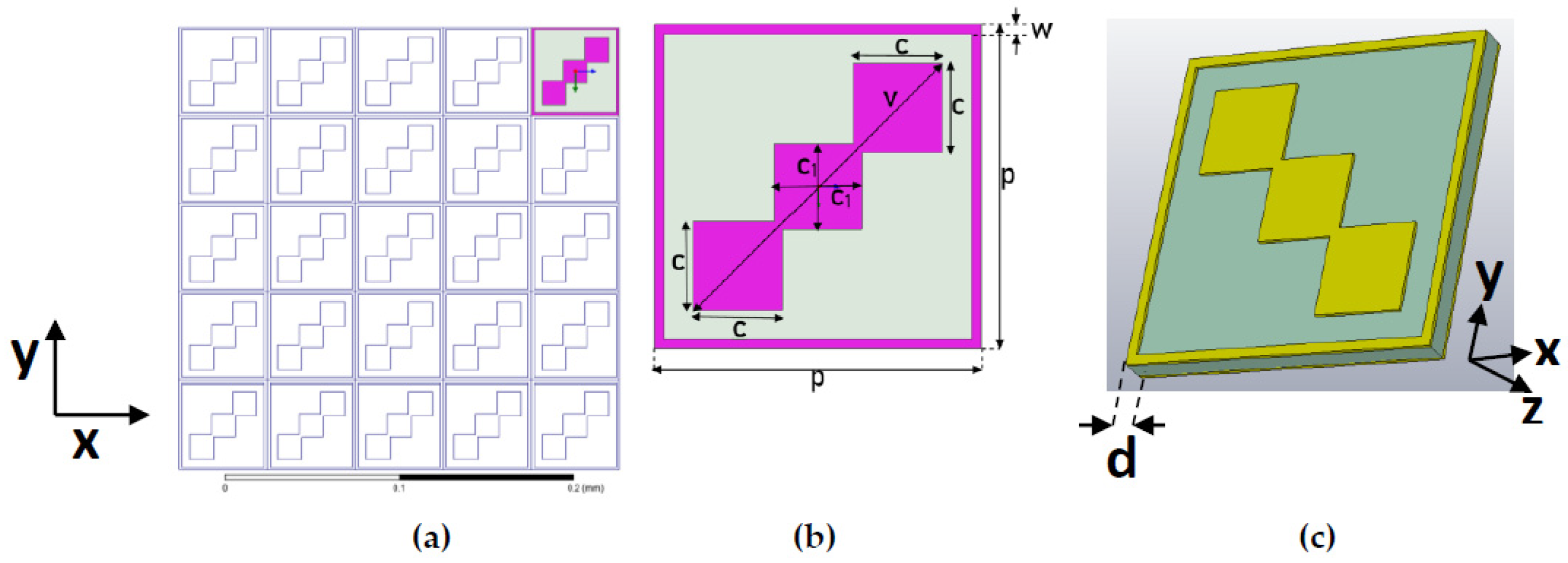
42]. A good choice is to have a diagonal symmetric structure so that incident wave can be divided into two equal orthogonal components. The first design consideration for the unit cell is to have two differently sized square patches, with each square corresponding to a single band LP-to-CP operation. They are arranged to have diagonal symmetry. The second consideration is a square ring to have closed form electric field distribution between the top and bottom surfaces. In a nutshell, the proposed structure is a diagonal symmetric structure which consists of multiple resonating structures to have wider bandwidths in two operational bands.
Figure 1 shows the design of the proposed converter. It consists of two identical sheets of conductor patches having substrate layer sandwiched between. Gold was used as a conductor and flexible polyimide having ε
r of 3.5 was used as a substrate. The shaded region in
Figure 1b shows the conductor layer, which consists of two parts: the outer part is a square ring consisting of a conductor with width
w and an inner part consisting of three squares diagonally intersecting each other. Top right and bottom left squares have dimensions
, while the middle square has dimension
×
. The bottom layer is identical to the top layer. The design was optimized to have the best results and optimized parameters for the unit cell, as follows:
p = 50.67 µm,
v = 54.65 µm,
c = 13.4 µm,
d = 3.5 µm,
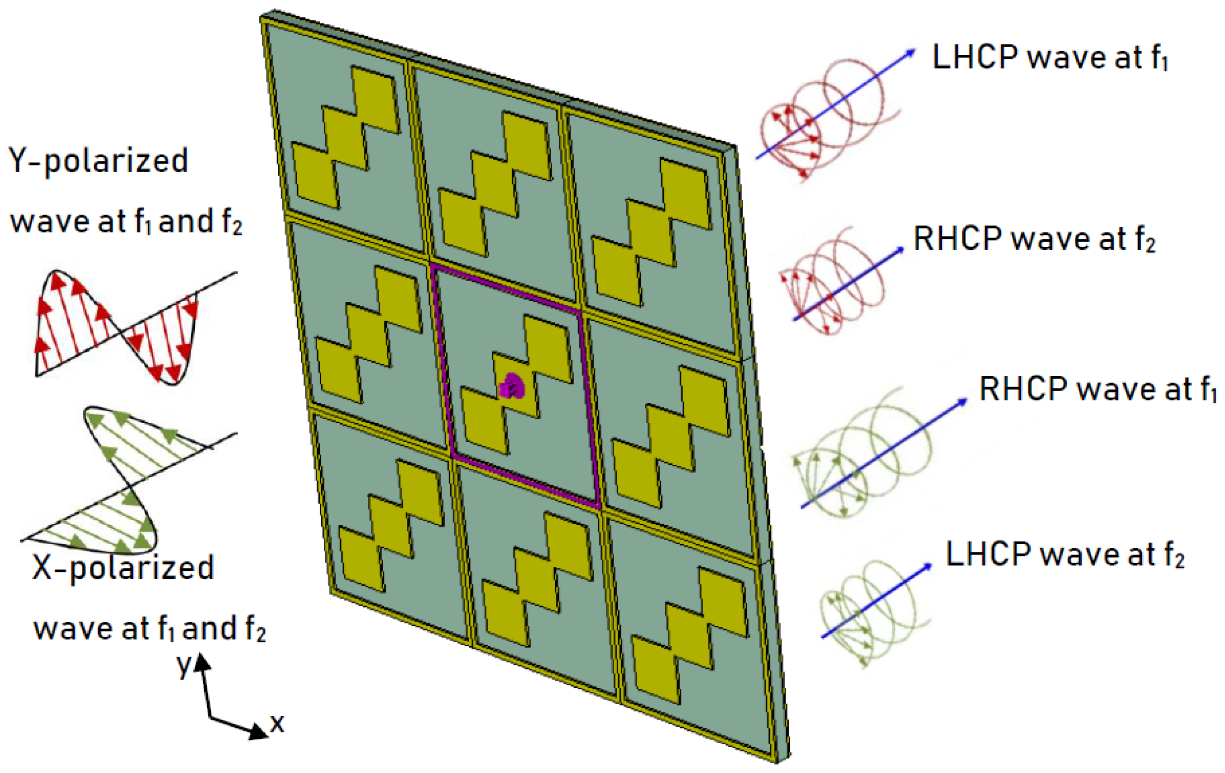
= 14 µm. The scheme for the operation of the dual-wide-band LP-to-CP converter is shown in
Figure 2.
4. Principle of Operation
In the topology diagram shown in
Figure 2, it is assumed that both X polarized and Y polarized waves can be made incident on the metasurface. The proposed device has different responses to incident X and Y polarized waves. For incident X polarized waves, transmitted waves behave as LHCP at f
1 and RHCP at f
2, whereas for incident Y polarized waves, transmitted waves behave as RHCP at f
1 and LHCP at f
2. In order to understand the operation of a dual-band LP-to-CP converter, a plane horizontal (X polarized) wave travelling in the -Z direction is made incident on the surface of the unit cell. The incident wave can be expressed by Equation (1). Magnitudes of this incident wave can be expressed by Equation (2).
where
is the unit cell in X direction. The transmitted wave can be expressed as the sum of two components, i.e., X polarized and Y polarized, as shown in Equation (3):
where t
xx and t
xy represent transmission coefficients for X to X and X to Y polarization conversion as shown in Equations (4) and (5), respectively.
and
are phase angles corresponding to t
xx and t
xy, respectively. Since the proposed structure has an anisotropic structure, the magnitudes and phasers for X polarized and Y polarized transmitted wave components may be different. However, if for a certain frequency range these transmission coefficients become comparable and their phase angles are 90° apart, i.e., t
xx = t
xy and
, with
being an integer, then the conditions for linear-to-circular polarization conversion will be met. In order to describe the transmission conversion performance of the proposed structure, the axial ratio for the transmitted wave is calculated as given in Equation (6) [
38]:
where a can be calculated from Equation (7) [
38]:
For an ideal LP-to-CP operation, AR should be 1 (0 dB). However, for most systems, a 3-dB value of the axial ratio is acceptable.
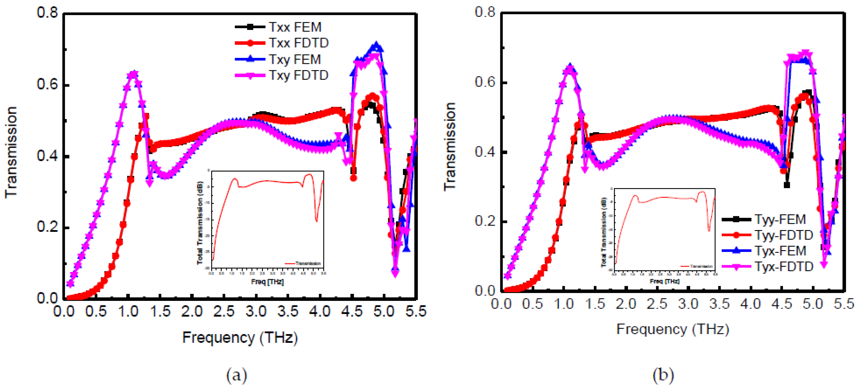
Figure 3a and
Figure 4 show that in frequency bands from 1.16 THz to 1.634 THz and 3.935 THz to 5.29 THz, the transmission coefficient magnitudes are comparable, and the phase difference between them is −90° or +270° with ±15° variation. Thus, the conditions for linear to circular polarization conversion is fully met at some frequencies, while for a range of frequencies, it partially fulfils the requirements (in this case the transmitted wave will be slightly elliptically polarized). Nonetheless, the performance criterion for linear to circular transmission type conversion (axial ratio within 3 dB) is maintained. Furthermore, in the frequency range from 1.16 THz to 1.634 THz, the Y component of the transmitted wave is ahead of the X component hence the transmitted wave is LHCP, whereas in the frequency range of 3.935 THz to 5.29 THz, the Y component of the transmitted wave lags the X component, hence the transmitted wave is RHCP. In addition, the proposed unit cell behaves equally well for the incident Y polarized wave resulting in RHCP and LHCP for the two frequency bands.
Total transmission in the X direction can be computed as
[
46].
Figure 5 shows the axial ratio for the incident X polarized and Y polarized waves along with total transmission. For the sake of simplicity, total transmission in the X direction is only shown in
Figure 5. A similar tendency is observed for transmission in the Y direction. It is clear from
Figure 5 that the proposed structure has an axial ratio of 3 dB from 1.16 THz to 1.634 THz and 3.935 THz to 5.29 THz for both X polarized and Y polarized incident waves. Moreover, reasonable energy transfer (−1 to −5 dB) is observed in the dual-band except in the frequency range 5 THz to 5.29 THz. In fact, there is good energy transfer from 1 THz to 5 THz but the transmitted wave from frequency range 1.634 THz to 3.935 THz is not circularly polarized wave because the axial ratio is much larger than 3 dB.
5. Physical Explanation and Equivalent Circuit
Since the unit cell is based on an anisotropic structure having dual diagonal symmetry, the incident X polarized wave will generate transmitted X and Y polarized wave components and the incident Y polarized wave will generate transmitted X and Y components. To explain the physical phenomenon behind the proposed LP-to-CP, we considered the surface current vectors within two frequency bands; let these be f
1 and f
2: f
1 = 1.398 THz and f
2 = 4.82 THz.
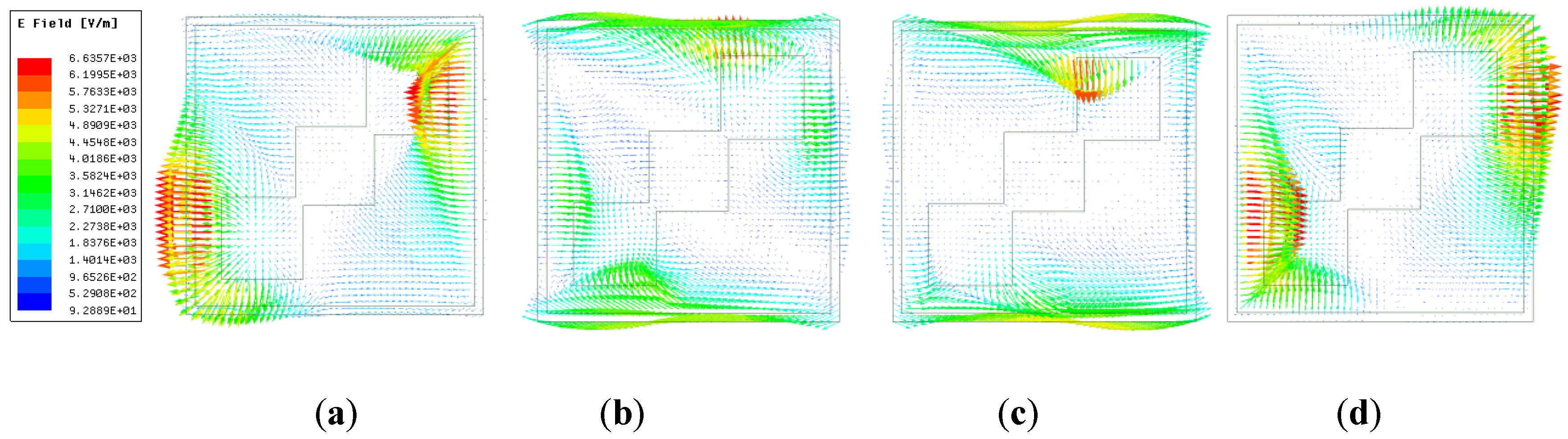
Figure 6 shows the surface current distribution with the incident X polarized wave at the output surface of the proposed converter for t = 0, T/4, T/2, 3T/4 at f
1. The orientation of the electric field vectors shows that with every T/4 cycle, it rotates by 90°. Further, it can be seen that the surface current at f
1 is concentrated in the inner tri-square conducting patches with an anti-clockwise rotation. Thus, the transmitted wave is LHCP at f
1.
Figure 7 shows the surface current vectors at the output surface at f
2. It can be clearly seen that with every quarter cycle, surface currents are rotated 90° in a clockwise rotation. Unlike in
Figure 6, this time surface current vectors are concentrated in the outer square ring. The opposite direction of rotation for surface current vectors in time cycle T validates our proposed opposite handedness of circular polarization for the same structure at two different frequencies.
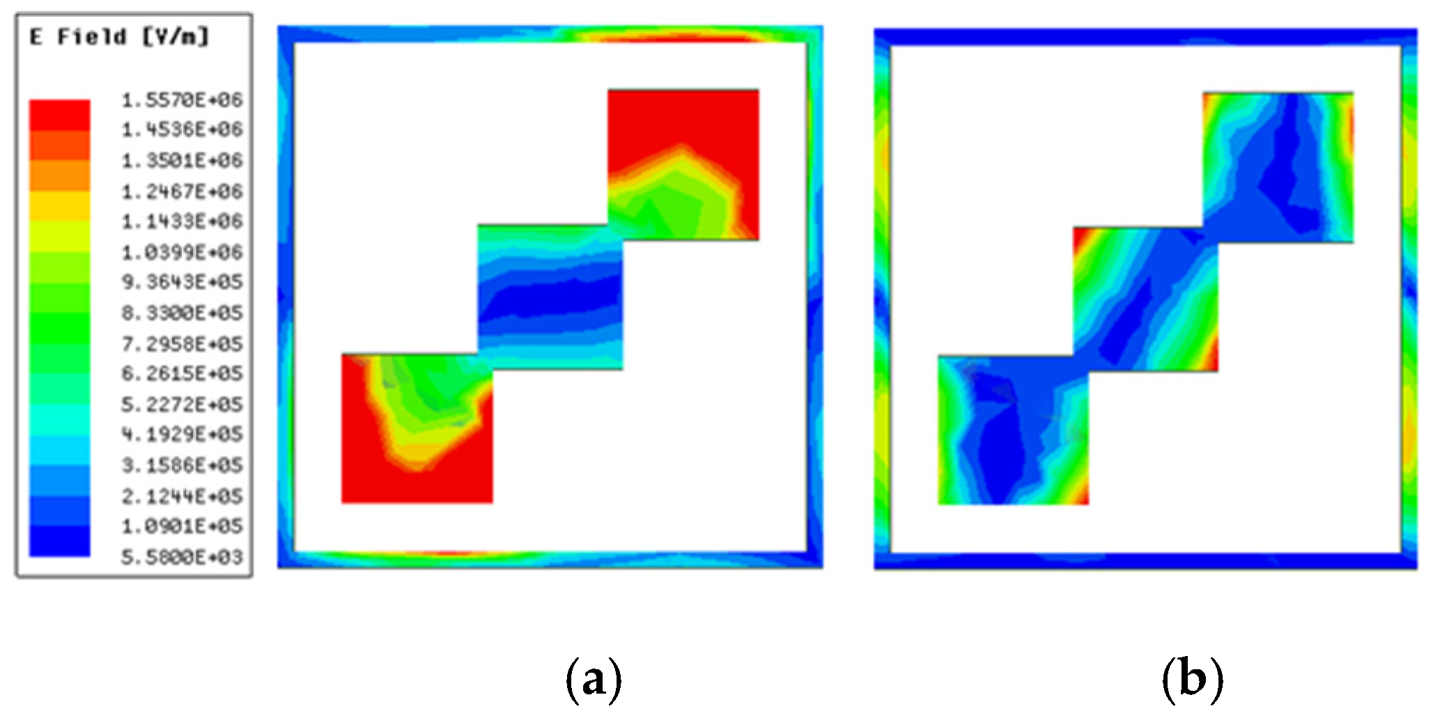
Figure 8 and
Figure 9 indicate the response of the proposed structure to the incident X polarized electromagnetic field.
Figure 8a,b show electric field distribution at 1.398 THz and 4.82 THz, respectively. It is clear from
Figure 8a that the electric field concentrates on the outer two conducting patches of the tri-square patch with a minor contribution from corners of an outer square ring, whereas for 4.82 THz, the electric field is concentrated on the whole tri-squares patch and outer square ring. This multi-resonance structure validates the dual-wide-band performance of polarization conversion.
Figure 9a shows the magnetic field strength at f
1 = 1.398 THz. It shows that the magnetic field is concentrated in the intersected corners of the tri-squares conductor patch.
Figure 9b shows that for the second frequency band, at f
2, the magnetic field is predominantly attributed to the outer square ring and vertical sides of the squares in the tri-square patch.
Figure 10a,b show the equivalent circuit for the unit cell of the proposed dual-wide-band LP-to-CP converter with incident X and Y polarizations, respectively. With incident X polarizations, upper and lower arms interact with the incident waves, whereas the left and right arms of the outer square ring will have no interaction. Thus, inductors L
1 representing the outer square ring will appear as shown in
Figure 10a. C
1 represents the value of capacitance induced between the corner of the square ring and the diagonal conducting patch with incident X polarization. L
2 shows the combined inductive effect of the two outer squares (area: C × C) and inner square (area: C
1 × C
1). It is interesting to note that due to the discontinuity between the three square inductors in a diagonal position, there will also be a capacitive effect, but the overall effect for three inductors will be inductive. Thus, it is represented as L
2. Z
o and Z
d represent transmission line models for free space layers and the substrate. In the lower frequency band of operation, the impedance corresponding to L
1, Z_L
1 will be lower compared to its value in a higher frequency band of operation. Similarly, impedance corresponding to C
1, Z_C
1 will be large in the first frequency band while it will become much smaller in the second frequency band.
Now it will be explained how dual polarizations exist within two bands. For this, assume Z_L1 (f1) and Z_L1 (f2) represent impedances corresponding to L1 at f1 and f2, respectively. Similarly, Z_C1 (f1) and Z_C1 (f2) represent impedances corresponding to C1 at f1 and f2, respectively, and Z_L2 (f1) and Z_L2 (f2) represent impedances corresponding to L2 at f1 and f2, respectively. f1 corresponds to any frequency within the first frequency band while f2 corresponds to any frequency within the second frequency band. Thus, |Z_L1 (f1)| < |Z_L1 (f2)|, |Z_C1 (f1)| >> |Z_C1 (f2)|, |Z_L2 (f1)| < |Z_L2 (f2)|. Overall impedance for the top layer can be calculated as |Z_L1| ‖ |Z_L1| ‖ (2 × |Z_C1| + |Z_L2|). At f1, |Z_C1(f1)| will be larger than that at f2, |Z_C1(f2)|. Thus, the 2 × |Z_C1| + |Z_L2| component will be larger. Hence, the overall effect for a parallel combination of large capacitive impedance and small inductive impedance will be small inductive impedance. For a frequency f2 in higher frequency band, 2 × |Z_C1| + |Z_L2| will become small and the overall effect will be capacitive. At f2, the resultant impedance will be a parallel combination of large inductance and small capacitance, which will result in small capacitive effect. Thus, the overall change in impedance behavior at f2 explains the idea of dual polarization.
6. Performance Analysis
For design considerations, the effect of different dimensions of the unit cell on the performance of the dual-band polarization converter was analyzed.
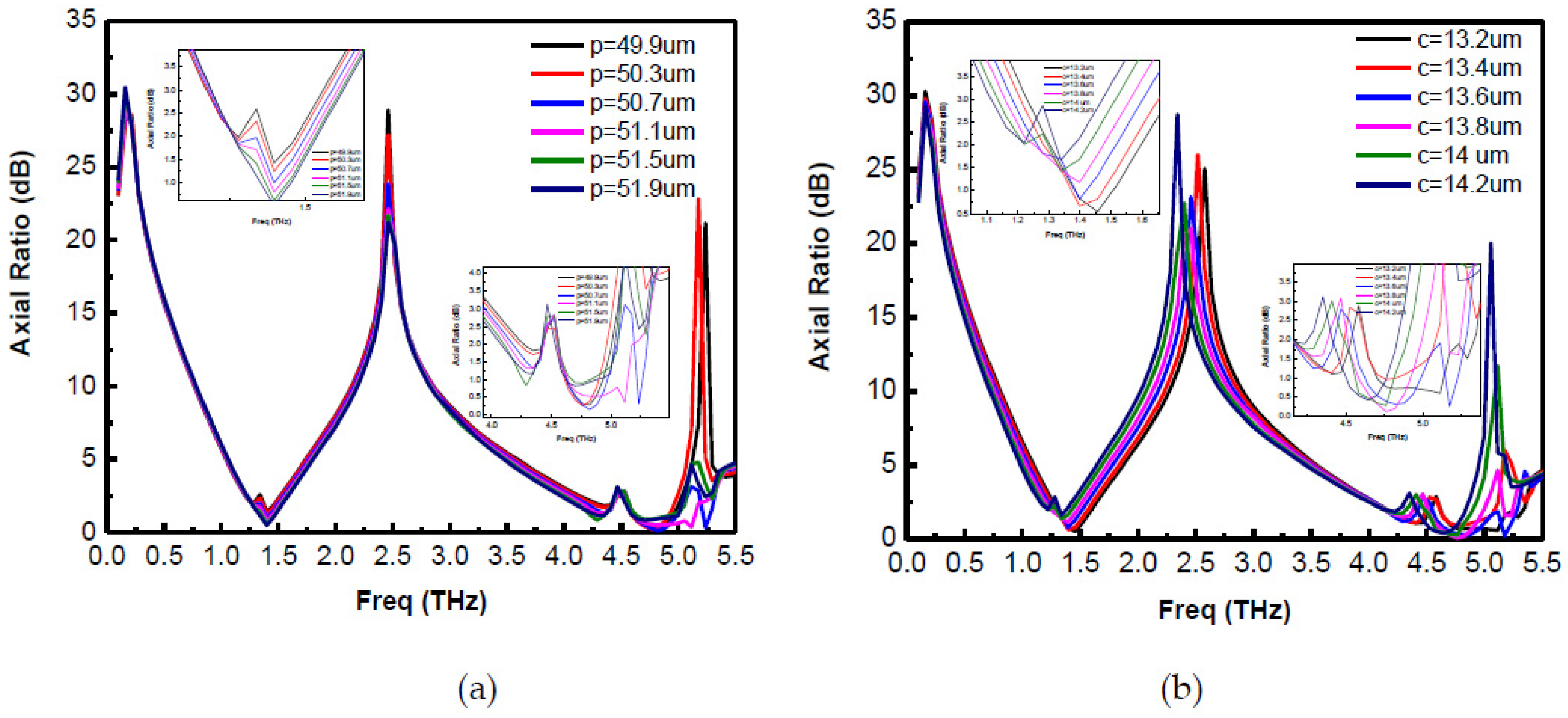
Figure 11a shows the plot of the axial ratio for the proposed converter for different values of
p keeping all the other parameters constant. It is observed that with the increase in
p from 49.9 µm to 51.9 µm, the lower end of the first frequency band remains almost constant while higher-end shifts towards the right cause the bandwidth of the first band to increase. In the second band, increasing
p has greater impact: it shifts the lower frequency towards the left while the higher-end remains almost stable with some exceptions. Thus, periodicity
p has an impact on both conversion bands. This can be explained as follows: increasing
p increases the length of the outer square ring on the metasurface, since this square ring contributes to the electric field strength at f
1 less than that at f
2 (as seen in
Figure 8). Thus, variation in the second conversion band is found to be larger than for the first conversion band.
Figure 11b shows the plot of the axial ratio for different values of
c from 13.2 µm to 14.2 µm. It is clear that with the increase in
c, the first frequency band shifts towards the left, which decreases operational bandwidth. A similar tendency is observed for the second frequency band due to the larger variation per wavelength as compared to the first frequency band. This change is supported by
Figure 8, in which both conversion bands’ operation depends upon corner square-conducting patches.
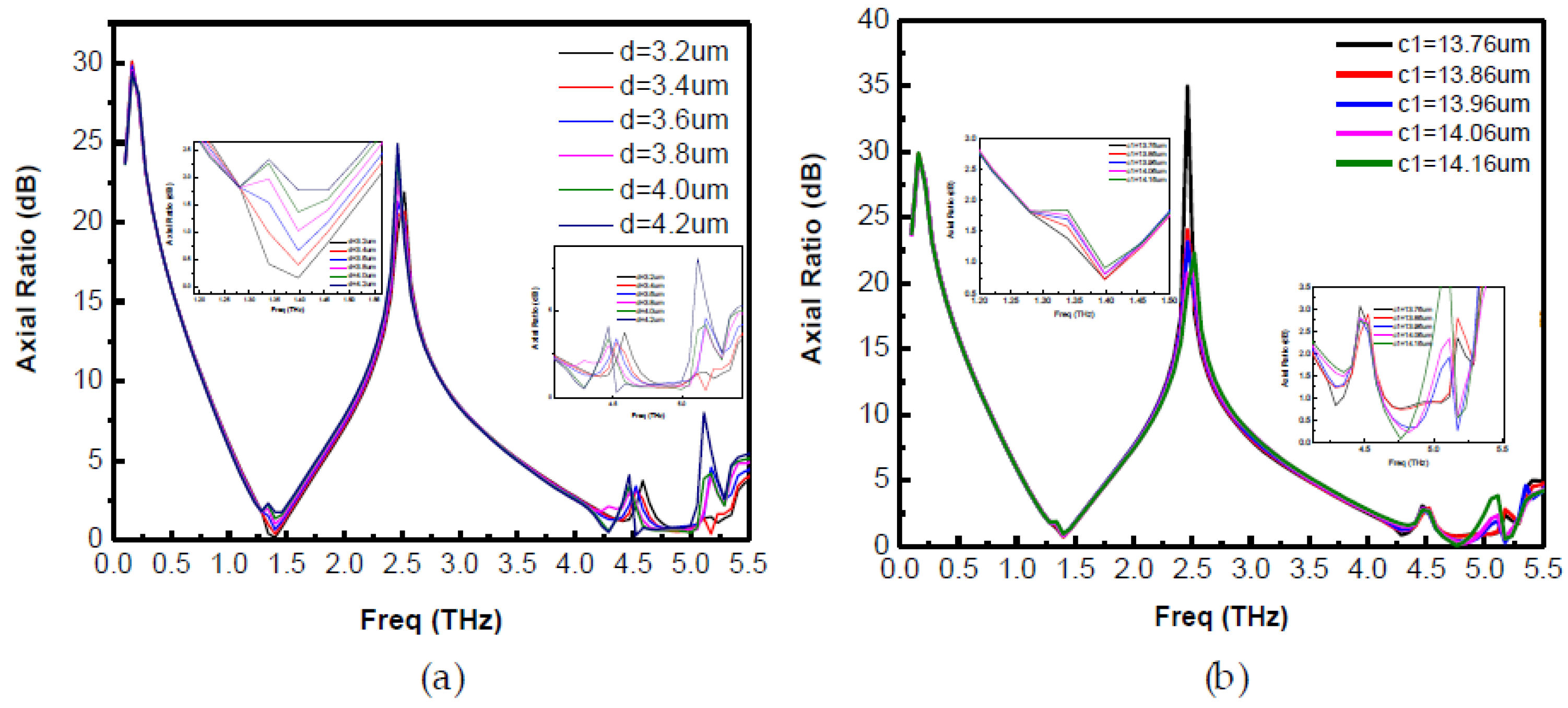
The effect of substrate thickness
d and inner square dimension
c1 is analyzed as shown in
Figure 12a,b, respectively.
Figure 12a shows that as
d is increased from 3.2 µm to 4.2 µm, the performance of dual-band LP-to-CP deteriorates in terms of axial ratio. A slight decrease in bandwidth is observed as the higher frequency end of the first band moves towards the left. This variation in second frequency band seems to be abrupt due to higher sensitivity at high frequency, although performance remains more or less stable (within 3 dB), except at
d = 4.2 µm. This phenomenon can be explained quantitatively as follows: the incident electric field on the top metasurface can be divided into two parts: the reflected wave to the air and the transmitted wave inside the substrate. Assuming the conductor thickness to be negligible, the transmitted wave travels inside the substrate and upon striking the substrate to the ground interface, is partially reflected back to the substrate, whereas the remainder of the portion is transmitted into the air. The portion of electromagnetic wave which was reflected back to the substrate travels back to the top surface to the substrate interface and, upon striking that interface, is again divided into two portions. One portion is reflected back to the substrate, while the other portion is transmitted into the air. The reflected wave traveling inside the substrate experiences the phase delays and, upon striking the substrate to ground interface, some portion of this wave reflects back to the substrate, while some part is transmitted into the air. These multiple transmitted waves interfere with each other constructively and destructively producing two polarized waves: one X polarized and the other Y polarized. These waves generate circularly polarized waves when they have comparable magnitudes and differences in phase angles around 90°. Varying the substrate thickness changes the phase angles and hence affects the axial ratio for the proposed converter.
Figure 12b shows the effect of
c1 on the performance of dual-band LP-to-CP converter. It shows that the first frequency band remains almost stable with a change in
c1, whereas the second frequency band is sensitive towards
c1. Although its performance remains within 3 dB for 13.76 to 14.06 um, the value of
c1 affects the second frequency band. The same is obvious from the physical mechanisms discussed earlier and as shown in
Figure 8, where it is clear that the central conducting patch contributes to the higher frequency band and does not significantly impact the lower frequency band.


