Real-Time Monte Carlo Optimization on FPGA for the Efficient and Reliable Message Chain Structure

1
School of Electronic Engineering, Kumoh National Institute of Technology, Gyeongbuk 39177, Korea
2
Agency for Defense Development, Daejeon 34186, Korea
*
Author to whom correspondence should be addressed.
Electronics 2019, 8(8), 866; https://doi.org/10.3390/electronics8080866
Submission received: 9 July 2019
/
Revised: 29 July 2019
/
Accepted: 2 August 2019
/
Published: 5 August 2019
(This article belongs to the Section Computer Science & Engineering)
Abstract
:This paper addresses the real-time optimization problem to find the most efficient and reliable message chain structure in data communications based on half-duplex command–response protocols such as MIL-STD-1553B communication systems. This paper proposes a real-time Monte Carlo optimization method implemented on field programmable gate arrays (FPGA) which can not only be conducted very quickly but also avoid the conflicts with other tasks on a central processing unit (CPU). Evaluation results showed that the proposed method can consistently find the optimal message chain structure within a quite small and deterministic time, which was much faster than the conventional Monte Carlo optimization method on a CPU.
1. Introduction
In the field of aerospace and defense, MIL-STD-1553B [1], which is a well-known military data communication standard based on half-duplex command–response protocols, has been widely used as data communication systems. It defines the mechanical, electrical, and functional characteristics of a serial data bus which consists of a bus controller (BC) controlling the data bus system, multiple remote terminals (RTs) responding to the commands of the BC, and monitoring devices (MTs), as shown in Figure 1. In the physical layer, the impact of a short circuit can be reduced by not only coupling transmitters and receivers to the bus through isolation transformers but also by using a pair of isolation resistors for stub connections to branch off. Although those physical implementations are good for electrical reliability, they cause a limitation of the bit rate to 1 Mbps. Besides, in the application layer, the available bandwidth is also limited because the data transmission is constrained by the required time for data processing in remote terminals.
Note that the excessive increase in the number of messages may reduce the channel reliability due to data loss caused by the lack of processing time in the RTs. To reduce the processing burden in the RTs, the BC can transmit data in the form of multiple message chains (MMCs), and double buffers (DBs) can be used in the RTs [2]. Then, the data throughput depends on the operation of the BC with the MMCs, and thus the transmission period and the number of messages in each MMC should be carefully determined to increase the data throughput without data loss.
Data Device Corporation [3] which is one of the major suppliers of the integrated chips for MIL-STD-1553B communications introduced two approaches to improve data throughput by increasing bit rate such as Turbo-1553 and Hyper-1553 in their white paper. Both approaches increased the bit rate by upgrading the chip hardware or changing modulation methods. However, Turbo-1553 requires the careful use of cables with reasonably good frequency response to reduce the impact of higher frequency on attenuation and phase distortion, which causes additional costs. Besides, the performance of Hyper-1553 is affected by the frequency band to avoid the inevitable harmonics. Zhang et al. [4] proposed a heuristic method which rearranges the components of the command table based on the number of command words or data words. Their method can be conducted in the original MIL-STD-1553B architecture. However, the data throughput varied according to the length of the resulting sets of command words. Besides, the processing time in the RT for the channel reliability was not considered in their work.
Optimization algorithms can be used to find the best message chain structure for the BC in MIL-STD-1553B communications. A sampling-based optimization algorithm such as the Monte Carlo optimization method is an appropriate choice because the constraints for the optimization of the BC are nonlinear. However, they may be faced with much computation time because of its large number of samples. Therefore, for real-time systems with the optimization process, the computation time should be reduced significantly. Recently, in various fields, the computation time for the Monte Carlo optimization method has been significantly reduced by hardware implementations on graphical processing units (GPU) and field-programmable gate arrays (FPGA). Liang et al. [5] proposed a GPU-based large-scale Monte Carlo simulation method for systems with long-range interactions. Their work reached remarkable speedup, compared with the serial implementation on a central processing unit (CPU). However, the GPU-based acceleration approaches are generally not recommended for aerospace and defense fields due to the heat problem caused by their high-power consumption.
The other approach for algorithm acceleration is to use FPGAs. Although there is various research on algorithm acceleration with FPGAs, the research on the acceleration of the Monte Carlo optimization or simulation algorithm with FPGAs is limited. We guessed that it may be because of the large amount of resources required to implement the Monte Carlo optimization on FPGAs, which may be not an efficient choice. Nevertheless, if the system is required in order to avoid the heat problem, the acceleration of the Monte Carlo optimization with FPGAs is the only choice. Although the following works are not directly related to our work, they were referred to in this paper because they also focused on the acceleration of the Monte Carlo simulation algorithm with FPGAs. Luu et al. [6] proposed a FPGA-based Monte Carlo computation method for light absorption for photodynamic cancer therapy. Their implementation achieved increased speedup and much lower power delay compared to the conventional software method based on a CPU. Ortega-Zamorano et al. [7] proposed a FPGA hardware acceleration method of Monte Carlo simulations for the Ising model, which is a paradigm of the statistical physics approach to the study of finite temperature equilibrium properties of many body systems. Their method also achieved remarkable speedup in comparison to a standard CPU-based method. Aliee et al. [8] proposed a fault tree analysis method based on stochastic logic implemented on FPGA. In their work, static and dynamic gates in the fault tree were translated into stochastic logic templates and implemented on FPGA, which was not only accurate but also much faster than the conventional methods conducted on CPU. Consequently, the FPGA-based methods and implementations can achieve not only increased speedup but also avoid the heat problem thanks to lower power consumption, which is entirely acceptable in real-time systems, especially in aerospace and defense systems. Therefore, we have approached the real-time optimization problem in the context of the hardware acceleration using FPGA. In our previous work [9], the real-time optimization problem was tackled by the real-time variant of the particle swarm optimization (PSO) [10] algorithm which was accurately conducted within a consistent time. However, we found that it needs to be improved in the following three contexts. First, it considered only the worst case in the timing diagram between the BC and the RTs. Second, the search space and solution were limited to integer numbers even though their implementations were based on fixed-point vectors. Third, the convergence performance of the PSO is generally better than that of the Monte Carlo optimization method, but the design complexity of the PSO is higher than that of the Monte Carlo optimization method.
This paper proposes a real-time Monte Carlo optimization method conducted on FPGA, which can find the most reliable and efficient message chain structure for MIL-STD-1553B communication systems with MMCs and DBs. The proposed method considers two constraints, which describe the time margin as a reliability constraint between the transmission period in the BC and the required time for data processing and responding in the RTs, and the design margin as an efficiency constraint between the transmission period and the required time to transmit messages in the BC. The cost function is derived from the two constraints with a weighing factor. The Monte Carlo optimization method is iteratively conducted using the cost function to find the optimal number of messages and the optimal transmission period. The proposed method can find accurately the optimal configuration, which consists of the transmission duration and the number of messages. Also, it can find quickly the optimal configuration using FPGA logic cells implemented by synthesizable hardware description language (HDL) codes. The main notations used in this paper are summarized in Table 1.
The remainder of this paper is organized as follows: Section 2 describes briefly the MIL-STD-1553B communication system with MMCs and DBs, and then the real-time optimization problem to find the most reliable and efficient message-chain structure is addressed. In Section 3, the proposed method with the Monte Carlo optimization method on FPGA is presented to solve the addressed problem. In Section 4, the evaluation results of the proposed method are described in detail with figures and tables. Finally, Section 5 gives conclusions.
2. Problem Description
2.1. MIL-STD-1553B Communications
The MIL-STD-1553B communication system is based on a serial data bus which transmits and receives data words or messages. Each word consists of three sync bits, sixteen data or command or status bits, and one parity bit. Each message is made up of one or more words, which must contain at least one command word [2]. Most messages contain at least one, and up to thirty-two, data words with the exception of mode commands. The size of messages are user-defined as a part of the communication operation. The messages transmitted from the BC are separated by a certain period known as the inter-message gap (IMG). Also, a message chain, which is a linked group of messages, can be used for convenience. Kim et al. [11] presented two types of message chains for MIL-STD-1553B: A single-message chain (SMC) composed of messages with the same subaddresses and a multi message chain (MMC) composed of messages with different subaddresses. They analyzed data throughput when the SMC or the MMC was applied to the BC. Additionally, for the channel reliability, they applied double buffers to the RT and analyzed data throughput when single buffers or double buffers were applied to the RT. In their results, the highest data throughput was shown with the MMC and the double buffers.
The overall timing diagram of data transmission with MMCs and the data processing in a RT with double buffers is described in Figure 2. At every , the BC transmits the MMC which consists of a certain number of messages, . The messages in the MMC are separated by intermessage gap times represented by , and the message gap time represented by includes . The MIL-STD-1553B chip in the RT requires the processing time for the end-of-message (EOM) interrupt, but its processing time is negligible. The RT also processes the interrupt service routine (ISR), and the required time for each message is represented by . HPT indicates the high priority tasks whose processing times are represented by in total because it is not consistent. Then, the data in each message of the current MMC are processed in one buffer, and the data in each message of the next MMC are processed in the other buffer, which is represented by . WRD indicates the time for writing the responding data, which are also represented by in total because it is too difficult to respectively measure the times. Consequently, the RT should finish the whole data processing for the current MMC in a buffer, and should be finished until the next MMC is received in the same buffer to avoid data loss.
2.2. Problem of Real-Time Optimization
Since double buffers were used in this work, unexpected data overwriting in the RT does not occur when double is more than . However, it is not recommended to naively increase to avoid the unexpected data overwriting because it causes a decrease in data throughput. Therefore, it is important to find the appropriate and to maximize the data throughput without data loss, as highlighted by the dotted circles in Figure 2. As the goal of this work was to conduct the maximization process in real time, it should be conducted as quickly as possible.
We approached the problem of maximizing the data throughput without data loss in the context of optimizing the parameters related to the data throughput and data loss. As the system constraints are nonlinear, the Monte Carlo optimization (MCO) algorithm was applied to the problem for the convenience of implementations, which is a widely used sampling-based optimization algorithm based on the Monte Carlo method. However, the whole process of the Monte Carlo optimization requires too much computation time because it was designed based on the concept of iterative processes. Moreover, the total computation time increases linearly as the number of samples increases, which affects the optimization accuracy. To resolve the real-time optimization problem, this paper proposes a real-time Monte Carlo optimization method implemented on FPGA. In the FPGA implementation, the required time for processing the Monte Carlo optimization can be significantly reduced because it is performed on physical connections. The conventional Monte Carlo optimization method, which is generally conducted on CPU, should be modified because algorithms on FPGAs are based on a different mechanism. In CPUs, a process generated by an application program is controlled by the operating system. Therefore, a developer does not need to consider the internal operation such as a program counter. However, in FPGAs, a developer should consider the order of operating a process because there is no operating system. Therefore, each process should be controlled by a clock counter, which counts the number of rising edges of the clock signal to avoid corrupting other processes.
3. Proposed Method
This section describes the proposed method in detail. First, the system constraints of the MIL-STD-1553B communications with MMCs and DBs are formulated. Then, the FPGA architecture of the proposed real-time MCO is presented. Finally, the core algorithm of the proposed real-time MCO on FPGA is described in detail.
3.1. Formulation of System Constraints
The overall process of formulating the system constraints was similar to our previous work [9]. But, in this work, and were regarded as Gaussian random variables, and , in order to include the uncertainty of the processing times for the ISR and received data in the RT, respectively. This was because we found that the and need to be treated as random variables from repetitive experiments with our real-time system. Our real-time system was implemented using commonly used DDR memories, and we found that the measurements for task times were not consistent. These empirical results are also supported by Micron which is one of the major DDR suppliers. In their technical report [12], which is newly added in the reference list, clock jitters in DDR2 and DDR3 systems are bound by clock jitter specifications in both positive and negative directions; the negative direction corresponds to a smaller clock period and the positive direction corresponds to a larger clock period. Therefore, the parameters affected by the clock jitters need to be modeled as random variables because the clock jitters are modeled as random variables. We modeled our system parameters such that and affected by clock jitters were Gaussian random variables.
The proposed method was formulated based on two constraints: A time margin constraint and a design margin constraint. The time margin constraint indicates the minimum of required to avoid the data overwriting in the RT. The design margin constraint indicates the maximum of and the corresponding required to avoid poor data throughput. Monte Carlo optimization was used to find the optimal and from the two constraints.
For the first constraint, which was the time constraint between the BC and the RT, at first, the total time to write the response data for the received MMC, , in the buffers of the RT was formulated. It could be respectively analyzed as the average times, and , for buffer writing before and after the transmission of the MMC from the BC to the RT is finished. Among the total number of messages transmitted from the BC to the RT, , the average number of messages before completely receiving the MMC is as follows:
where is the number of responding messages written in the response buffers, which is also represented by a random variable because is a random variable, and ⌈ ∙ ⌉ describes the ceiling function. Then, the total writing time for the response data can be modeled as follows:
where is also represented by a random variable because is a random variable. Then, the total required time in the RT can be computed as follows:
where is also represented by a random variable because is a random variable. Then, the first system constraint which indicates the time margin can be formulated as follows:
The left term of the above inequality is a deterministic value while the right term is a random variable. For the simplicity, we converted the Gaussian random variables into the largest and the smallest deterministic values using three-sigma approximation, which is described in the next subsection.
The second constraint, which is the design margin constraint, describes the time gap between and the required time for the only transmission of the MMC in the BC. Too much of a design margin degenerates the data throughput, therefore, the design margin needs to be carefully derived to maximize the data throughput without data loss. Note that the smaller time gap without data loss indicates the more data throughput. Then, the second constraint which indicates the design margin, α, can be formulated as follows:
where . The larger indicates the greater design margin. Differently from the first constraint, both sides of the inequality for the second constraint are deterministic values.
3.2. Monte Carlo Optimization
The Monte Carlo Optimization (MCO) algorithm [13,14,15,16,17,18] is one of the sampling-based optimization algorithms, which relies on repeated random sampling to obtain the optimal configuration from the defined search space. The MCO has been widely used in various fields of sciences and engineering in spite of its high computational load, because it can be simply implemented and has shown good performance even though the constraints and the corresponding objective functions are complex and nonlinear. The processing flow of applying the conventional MCO on CPU to our system with the formulated constraints is shown in Figure 3.
First, the whole given search space was initialized as shown in Figure 3a, and the process of sampling the candidate configurations for and was conducted. Next, the time and design margin constraints for the sampled configuration were sequentially calculated. Then, the objective value matrix was iteratively updated based on the objective function for every sampled configuration as shown in Figure 3b,c. The minimum objective value was bounded to −10 for the convenience of visual analysis. Finally, if the MCO reached the predetermined number of samples, , the row and column indicating the maximum in the objective value matrix was selected as the optimal configuration. In our system, the optimal configuration acquired by the conventional MCO on CPU was as follows: = 11 msg and = 8.6 ms as shown in Figure 3d. Therefore, the maximum data throughput was about 1.279 msg/ms.
3.3. FPGA-Based Real-Time MCO
To reduce the computation time for real-time systems, this paper proposes an FPGA-based real-time MCO (FRMCO), which can find the most efficient and reliable message chain structure in MIL-STD-1553B communications. The main differences between the conventional MCO and the FRMCO are summarized in Table 2. The main advantage of the FRMCO is the parallelizability with look-up tables (LUTs), which are more flexible and scalable than CPU cores. All the variables and constants consisted of two 18-bit fixed-point vectors as shown in Figure 4 to be implemented on FPGA, and each vector consisted of one sign bit, four dummy bits for fixed-point multiplication, four integer bits, and nine decimal bits. This definition is different from our previous work because the proposed method in this work was implemented to improve the resolution of computing the constraints and acquiring the optimization solution.
The FPGA structure of the FRMCO is shown in Figure 5. At every rising edge of the clock produced by phase-locked loop (PLL), the FRMCO was conducted with two counters: The clock counter (CC) to control algorithm processes and the sample number counter (SNC) to differentiate samples in each group. The CC was used in all the states regardless of the dependency among samples. However, the SNC was only used in the states with dependency among samples, and the FRMCO was performed partially in parallel. In the states without dependency among samples, the FRMCO was performed entirely in parallel. The states before finding the global best configuration were conducted with the multiple groups of samples in parallel. The multiplication and division were conducted by FixedP_Mul and FixedP_Div, respectively. In our implementation, FixedP_Div was used for the calculation of constraints (part #1) and the calculation of the objective function. The core algorithm of the FRMCO was conducted in MCO_CORE, which consists of more logic blocks than the conventional MCO on CPU. This was because the FRMCO should be implemented with the consideration of avoiding the data loss caused by clock sharing for variable updates among logic blocks with data dependency. For example, if a logic block has variables which may be rewritten for updates in the same clock, it should be divided by multiple logic blocks and processed independently. The pseudo random number generator (PRNG) was simply implemented based on linear-feedback shift registers (LFSR) [19]. This may be replaced by other types of the PRNG such as PRNG based on dynamical chaos [20,21,22], which will be tried for our next works.
The pseudo-code of conducting the core algorithm of the FRMCO is shown in Algorithm 1. In our system, the frequency of the original clock signal for FPGA was 25 MHz. This was enough for handling discrete signals and IO interfaces. However, it was too slow to handle the complex logics of the Monte Carlo optimization algorithm. Therefore, we utilized the PLL to increase the frequency of the clock signal, which was simply implemented by the embedded IP in Xilinx Vivado. The processing flow was different from the conventional MCO on CPU because the FRMCO was modified to utilize the hardware resources for parallel processing. First, the whole search space was initialized, and the sampled configurations were allocated to multiple groups. When and denote and , respectively, a two-dimensional configuration in the m-th group, , was sampled from the defined search space where and . Here, and were the allowable maximum values of and for a target system, respectively.
Algorithm 1. The pseudo-code of the core algorithm of the FRMCO.
| Algorithm: | FPGA-based Real-Time Monte Carlo Optimization (FRMCO) |
| Input: | Initial vector, clock (clk_i), reset signal (rst_i), PRNG start signal (start_i) |
| Output: | Result vector |
| 1: | Start the phase-locked loop block with clk_i and generate clk_p |
| 2: | Start the PRNG block with start_i |
| 3: | Initialize the FixedP_Mul and the Fixed_Div blocks with clk_p and rst_i |
| 4: | Initialize the signals and variables in the MCO_CORE block with clk_p and rst_i |
| 5: | Process for the MCO_CORE block |
| 6: | Initialize the MCO state, clock counter (CC), sample number counter (SNC) |
| 7: | Iterate the loop controlled by CC and SNC |
| 8: | Sample particles using the PRNG block from the given search space |
| 9: | Truncate the sampled particles for the target format |
| 10: | Calculate a part of the time constraint in Equation (6) |
| 11: | Calculate the constraints by Equations (6) and (7) |
| 12: | Calculate the objective function by Equation (8) |
| 13: | Connect the global best configuration to the assigned output pins |
| 14: | End loop |
| 15: | Find the best configuration in each group |
| 16: | Find the global best configuration as the optimal value |
| 17: | End process |
Next, the time and design margin constraints for the sampled configuration were respectively calculated by modifying Equations (4) and (5) with consideration of the uncertainties of and as follows:
where the uncertainties of and were modeled by the three-sigma rule with Gaussian distribution. and are respectively the mean and standard deviation of . and are respectively the mean and standard deviation of . To consider both the worst case and the best case, the lower and the upper limits of them were used to calculate the constraints, which is one of the differences from our previous work. Based on and , the objective value for the sampled configuration at the current iteration can be calculated as follows:
where ω is the weighting factor, which was set to 0.5. Then, the objective value matrix was iteratively updated based on for every sampled configuration.
Finally, if the MCO reached the predetermined number of samples, , the row and column indicating the minimum in the objective value matrix was selected as the optimal configuration, , for and as follows:
4. Implementation and Evaluations
4.1. Implementation
The FRMCO was implemented on the Xilinx FPGA Kintex-7 (XC7K160T) with synthesizable VHDL codes. The simulations and evaluations of the FRMCO were conducted by Xilinx Vivado. The synthesis and implementation with 90 MHz PLL clocks were successfully completed. If the PLL output frequency of the clock signal exceeded 90 MHz, the synthesis and implementation processes failed. The utilization and timing results of the postimplementation of the FRMCO with 500 samples in 20 groups are summarized in Table 3 and Table 4, respectively.
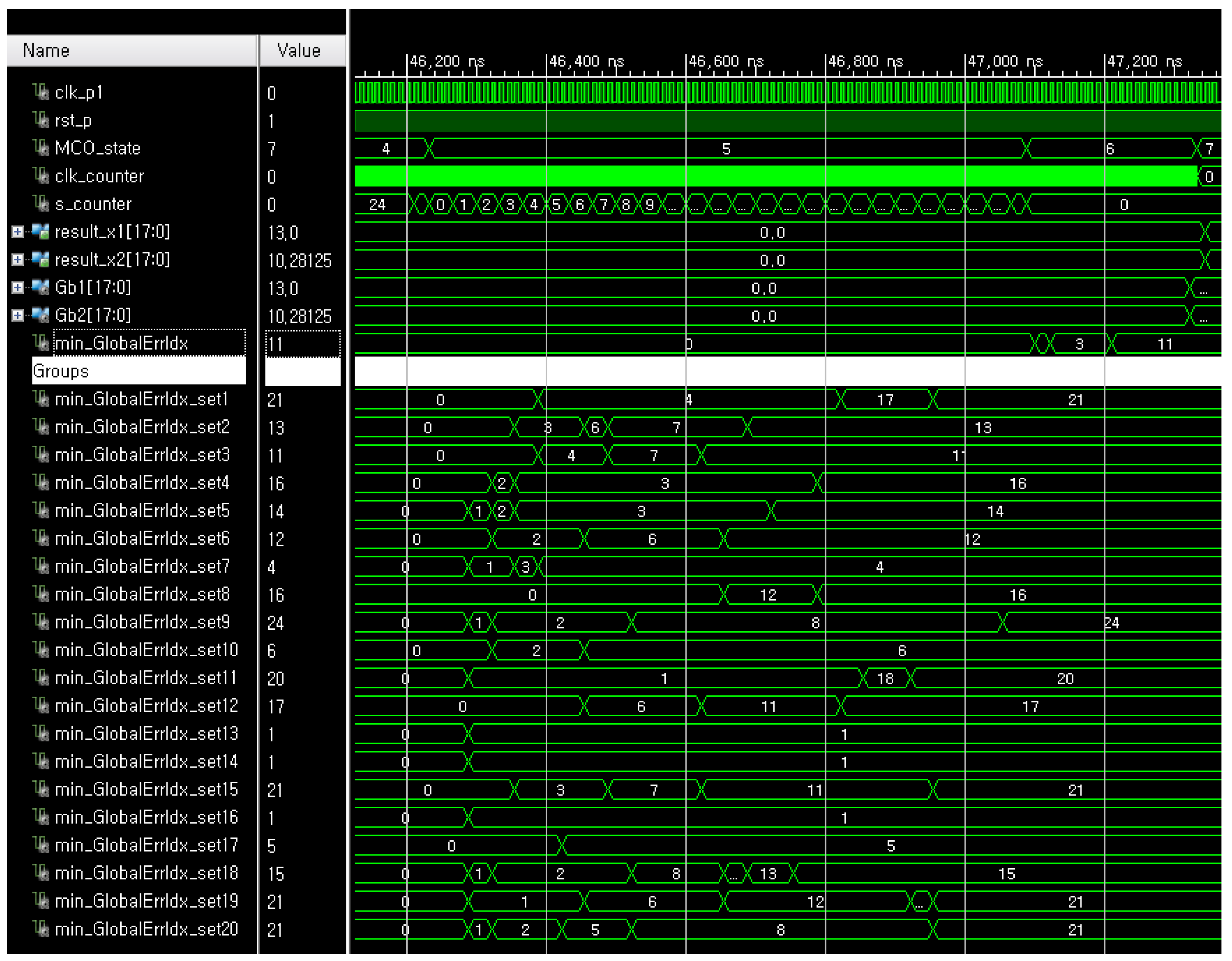
For simulations, we chose 500 samples because the minimum number of samples which can consistently show the optimal results was 500. The greater the number of samples, the better optimization performance of the MCO, therefore, it was also expected to show the good results of the FRMCO with a greater number of samples. The number of groups indicates the degree parallelization of the FRMCO, which means that the more groups, the more parallelized processes and the smaller computation time. In this work, the number of groups was empirically chosen to properly show the computation time of the FRMCO is much smaller than the conventional MCO on CPUs. Obviously, if the FRMCO is implemented with an increasing number of groups over 20, the computation time can decrease accordingly. The whole simulation result of the FRMCO with 500 samples in 20 groups when the design margin α = 0 is as shown in Figure 6. Gb1 and Gb2 indicate, respectively, and and successfully converge the optimal configuration of fixed-point binary vectors. sx1_setm and sx2_setm represent the two-dimensional configurations of the samples in the m-th group, respectively. The whole sampling process was done at the initial state denoted by the MCO_state 0 in the FRMCO, and the objective values were calculated at the MCO_state 4. The detailed simulation result of finding the best group and the best configuration at the MCO_state 5 and the MCO_state 6 in the FRMCO with 500 samples in 20 groups when α = 0 is as shown in Figure 7. The FRMCO found the best configuration in each group at the MCO_state 5, and the FRMCO found the global best group at the MCO_state 6. Then, at the MCO_state 7, the FRMCO decided finally the best configuration in the best group as the global best configuration.
The visualization of the objective values in the search space at the final iteration of the FRMCO is shown in Figure 8. Each objective value was inversely represented for visual convenience. Based on the optimization results, the maximized data throughput, P_max, can be simply obtained using the optimization results as follows:
where and are respectively the optimal and , which are the first and the second elements of . The FRMCO found that and were, respectively, 13 msgs and 10.2 ms, which indicates that the maximum throughput was 1.2745 msg/ms. In our previous work [11], we empirically determined and as five messages and 5 ms. Thus, the maximum data throughput was 1.0 msg/ms, which indicates that the maximum data throughput increased by 27.45% with the proposed method. These optimization results by the FRMCO were slightly different from the optimization results by the conventional MCO, 11 msgs and 8.6 ms as shown in Figure 3d, which indicates that the maximum throughput was 1.2790 msg/ms. This was because the quantization errors occurred when the FRMCO used the fixed-point vectors with limited number of bits used, which will be evaluated and analyzed in the next section.
4.2. Evaluations
The evaluations of the FRMCO were conducted by Xilinx Vivado with 90 MHz PLL clocks. The number of samples used for the FRMCO was 500 to 3000. The minimum number of samples was determined as the number of samples which can obtain consistently the correct optimal result. The maximum number of samples was determined as the number of samples which can be implemented on the target FPGA, Xilinx FPGA Kintex-7. This was because the implementation on FPGA depends on the number of hardware resources, especially LUTs.
To analyze the performance of the FRMCO according to the transmission margin, the optimization results of the FRPSO with 500 samples according to α were evaluated as shown in Figure 9. The FRPSO found successfully the optimal configurations regardless of α, which indicates that the FRPSO can be applied to various systems with different requirements. Obviously, the maximum throughput with the optimal configuration was affected by α, which shows that the more α caused the smaller maximum throughput. Therefore, the design of the message chain structure should be carefully conducted by considering the trade-off relation between the maximum throughput and the transmission margin.
Since the number of samples, , in the FRMCO is an important parameter which can affect the performance of optimization, the proposed method needs to be evaluated with the different number of samples. Also, the computation time of the proposed method needs to be evaluated with the different number of samples because the computation time of the MCO increases as increases generally. When α is fixed to 0.0, the maximized data throughput results and the computation times according to are as shown in Figure 10. The test range of was from 500 to 4000. The lower bound was determined to show consistent optimal results as described in the previous subsection, and the upper bound was determined to ensure that the FRMCO can be synthesized and implemented. As shown in the figure, the proposed method consistently obtained the maximum data throughput, which indicates that the proposed method can be performed successfully in the test range. Note that each computation time in the figure was not averaged over multiple results because the computation time of the FRMCO was deterministic with fixed algorithm and system parameters. As expected, the computation time increased as increased with an approximately linear slope.
To analyze how the FRMCO can reduce the computation time of the conventional MCO, the computation times of the FRMCO were compared with those of the conventional MCO according to as shown in Figure 11. The computation times of the conventional MCO were acquired by a desktop computer with 1.8 GHz CPU clocks. Each value of the conventional MCO in the figure was averaged from 10 tests. Obviously, the computation times of the FRPSO were smaller than those of the conventional MCO with the same optimization results. The computation time was averagely reduced by 44.34% using the FRMCO. The increased amounts of processing times for the FRMCO according to were also smaller than those of the conventional MCO. This was because the FRMCO was designed to be conducted in parallel using the resources in FPGA. Moreover, if the number of samples is fixed, the computation time of the FRMCO is consistent because the processing lines in FPGA are physically allocated and connected, while the conventional MCO is affected by other communication tasks on CPU. Therefore, the FRMCO benefits the task scheduling in real-time systems because of fast computation time and independency from other tasks.
The utilization results of the FRMCO according to are shown in Figure 12. Obviously, more samples lead to more accurate optimization results. However, more samples cause excessive utilization. As this is a trade-off relation, a developer has to find the appropriate number of samples with the consideration of other functions on the FPGA. When the FRMCO used 4000 samples, the utilization result of the LUTs, which are the critical hardware resource on the FPGA, was 58.39% as described in Figure 12, and the computation time of the proposed method was about 0.3643 ms as described in Figure 10. This means that the FRMCO is fast enough to be conducted in real time even though the critical hardware resources are utilized considerably. The LUT was generally the main factor to affect the implementation availability of the FRMCO. However, the LUTs used with 4000 samples were smaller than the LUTs used with 3500 samples. This was because the Xilinx Vivado implemented the FRMCO using more FFs than LUTs, which means that the FF was also an important factor to affect the implementation availability. Note, that in spite of the small number of samples such as 500 and 1000, the proposed method found the optimal configuration, which led to the maximum throughput. Besides, for the small number of samples, the computation times of the proposed method were still smaller than those of the algorithm on CPU. Consequently, the proposed method can be conducted with the small number of resources by adjusting the number of samples in the algorithm, which may lead to using cheaper FPGAs than the FPGA used in this work. The variations of the LUTRAM, BRAM, DSP, BUFG, IO, and PLL were not significant according to . The utilization results of the FPGA resources can be affected by variable definitions, algorithm structures, and logics. Note, that the variable definitions, structure, and logics of the FRMCO were designed to be parallelized and applied to real-time optimization by reducing the computation time with FPGA resources.
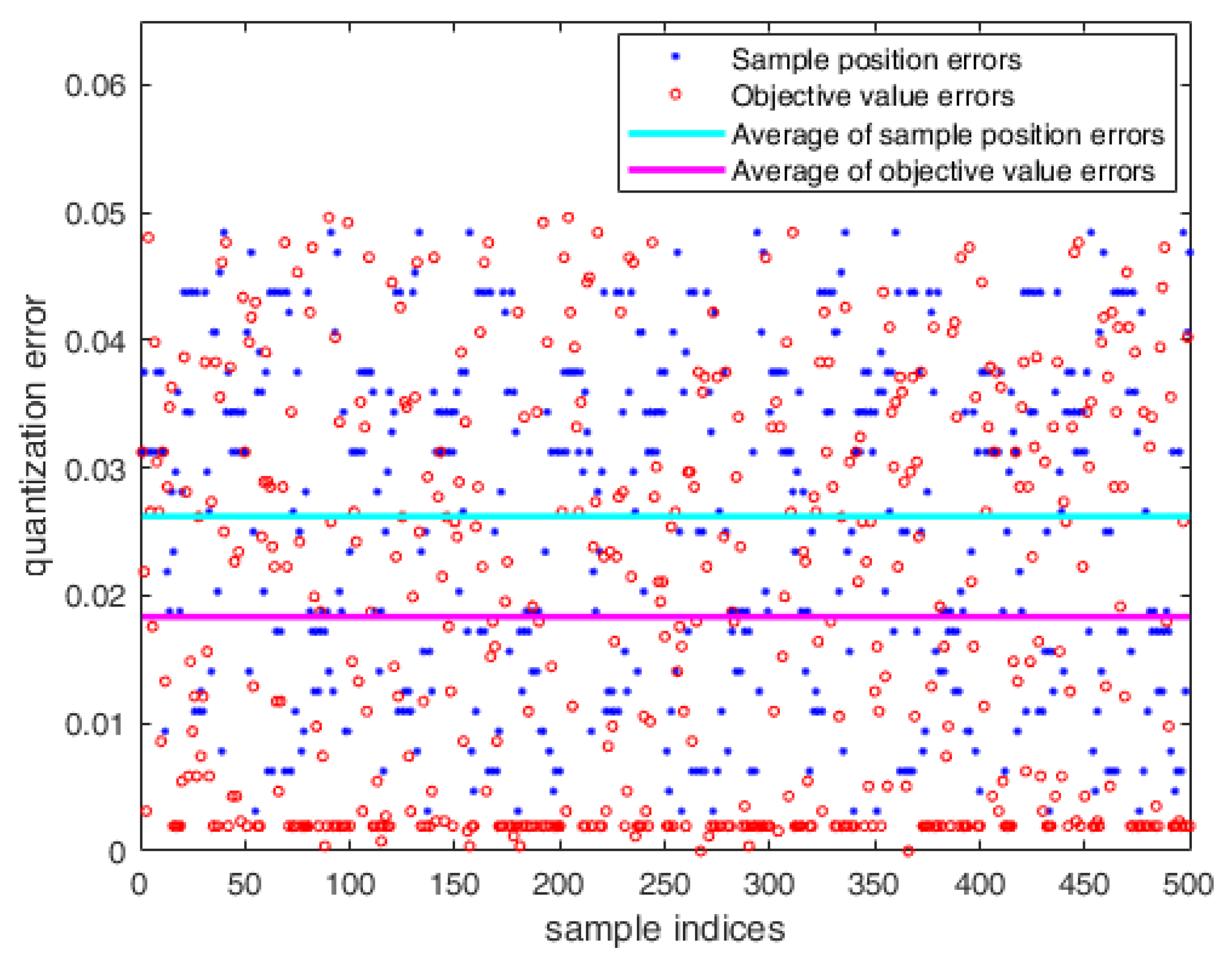
As the sample in the FRMCO was defined and calculated with 18 bit fix-point vectors, the quantization errors between the results of the conventional MCO and the FRMCO occurred inevitably. The quantization errors for sample positions and objective values between the conventional MCO and the FRMCO with 500 samples were evaluated as shown in Figure 13. The average of the quantization errors in sample positions was 0.0262, and the average of the quantization errors in objective values was 0.0183, which were absolute values. In other words, for the number of messages, since the full scale was 13 messages, the percentages of quantization errors in sample positions and objective values were about 0.20% and 0.14%, respectively. For the transmission period, since the full scale was 15 ms, the percentages of quantization errors in sample positions and objective values were about 0.17% and 0.12%, respectively. Both were not significant in the context of the accuracy of the optimization.
In summary, this work was focused on the extension of the conventional MCO to the real-time optimization problem in data communications with half-duplex command–response protocols. The contributions of this work are as follows. First, the conventional MCO on CPU to find the optimal message chain structure was modified to be hardware friendly, and implemented on FPGA. Second, since the proposed new variant of the MCO is parallelized with hardware resources on FPGA, its computation time is much smaller than the conventional MCO. Third, as the proposed variant is conducted on FPGA, it can avoid the conflicts with other tasks on CPU.
5. Conclusions
This paper proposed the FPGA-based real-time Monte Carlo optimization method, which is a hardware friendly variant of the conventional Monte Carlo optimization, to optimize the message chain structure in real-time. The proposed method can not only be conducted very quickly but also avoid the conflicts with other tasks on CPU, which was implemented and conducted on FPGA with synthesizable hardware description language codes. The simulation and evaluation results showed that the proposed method can successfully find the optimal configuration with much smaller computation time than the conventional Monte Carlo optimization. Also, its performance was consistent in spite of different system and algorithm parameters. The implementation availability of the proposed method according to the number of samples was also evaluated and analyzed with FPGA resources. Consequently, the proposed method is good for the real-time optimization of the message chain structure in half-duplex command–response data communications.
Author Contributions
All authors contributed the present paper with the same effort in describing the problem, finding available literatures, and writing the paper. H.L. designed and implemented the proposed method to resolve the problem. K.K. addressed the topic and proposed the idea to resolve it.
Funding
This research received no external funding.
Acknowledgments
This research was supported by the MSIT (Ministry of Science, ICT), Korea, under the ITRC (Information Technology Research Center) support program (IITP-2019-2014-1-00639) supervised by the IITP (Institute for Information and Communications Technology Planning and Evaluation).
Conflicts of Interest
The authors declare no conflict of interest.
References
- MIL-STD-1553B NOTICE II; Department of Defense: Washington, DC, USA, 1986.
- MIL-STD-1553B Designer’s Guide; Data Device Corporation: Bohemia, NY, USA, 1998.
- MIL-STD-1553B Evolves with the Times; White Paper; Data Device Corporation: Bohemia, NY, USA, 2010.
- Zhang, J.; Liu, M.; Shi, G.; Pan, W. A MIL-STD-1553B bus command optimization algorithm based on load balance. Appl. Mech. Mater. 2012, 130, 3839–3842. [Google Scholar] [CrossRef]
- Liang, Y.; Xing, X.; Li, Y. A GPU-based large-scale Monte Carlo simulation method for systems with long-range interactions. J. Comput. Phys. 2018, 338, 252–268. [Google Scholar] [CrossRef]
- Luu, J.; Redmond, K.; Lo, W.C.Y.; Chow, P.; Lilge, L.; Rose, J. FPGA-based Monte Carlo Computation of Light Absorption for Photodynamic Cancer Therapy. In Proceedings of the IEEE Symposium on Field Programmable Custom Computing Machines, Napa, CA, USA, 5–7 April 2009. [Google Scholar]
- Ortega-Zamorano, F.; Montemurro, M.A.; Cannas, S.A.; Jerez, J.M.; Franco, L. FPGA Hardware Acceleration of Monte Carlo Simulations for the Ising Model. IEEE Trans. Parallel Distrib. Syst. 2016, 27, 2618–2627. [Google Scholar] [CrossRef]
- Aliee, H.; Zarandi, H.R. Fast and accurate fault tree analysis based on stochastic logic implemented on field-programmable gate arrays. IEEE Trans. Reliab. 2013, 62, 13–22. [Google Scholar] [CrossRef]
- Lee, H.; Kim, K.; Kwon, Y.; Hong, E. Real-Time Particle Swarm Optimization on FPGA for the Optimal Message-Chain Structure. Electronic 2018, 7, 274. [Google Scholar] [CrossRef]
- Kennedy, J.; Eberhart, R. Particle Swarm Optimization. In Proceedings of the IEEE International Conference on Neural Networks, Perth, Australia, 27 November–1 December 1995; pp. 1942–1948. [Google Scholar]
- Kim, K.; Ahn, K.; Kwon, Y.; Yun, S.; Lee, S. Analysis and implementation of high speed data processing technology using multi-message chain and double buffering method with MIL-STD-1553B. J. Korea Inst. Mil. Sci. Technol. 2013, 16, 422–429. [Google Scholar] [CrossRef]
- Design Guide—Dealing with DDR2/DDR3 Clock Jitter; Technical Note TN-04-56; Micron Technology, Inc.: Boise County, ID, USA, 2008.
- Hastings, W.K. Monte Carlo sampling methods using Markov chains and their applications. Biometrika 1970, 57, 97–109. [Google Scholar] [CrossRef]
- Doucet, A.; Logothetis, A.; Krishnamurthy, V. Stochastic sampling algorithms for state estimation in jump Markov linear systems. IEEE Trans. Autom. Control 2000, 45, 188–202. [Google Scholar] [CrossRef]
- Spall, J.C. Estimation via Markov chain Monte Carlo. IEEE Control. Syst. Mag. 2003, 23, 34–45. [Google Scholar]
- Fishman, G.S. Monte Carlo: Concepts, Algorithms and Applications; Springer: New York, NY, USA, 1996. [Google Scholar]
- Kroese, D.P.; Taimre, T.; Botev, Z.I. Handbook of Monte Carlo Methods; John Wiley & Sons: Hoboken, NJ, USA, September 2011. [Google Scholar]
- Rubinstein, R.Y.; Ridder, A.; Vaisman, R. Fast Sequential Monte Carlo methods for counting and optimization; John Wiley & Sons: Hoboken, NJ, USA, 2013. [Google Scholar]
- Press, W.; Teukolsky, S.; Vetterling, W.; Flannery, B. Numerical Recipes: The Art of Scientific Computing, 3rd ed.; Cambridge University Press: Cambridge, UK, 2007; p. 386. [Google Scholar]
- Tutueva, A.V.; Butusov, D.N.; Pesterev, D.O.; Belkin, D.A.; Ryzhov, N.G. Novel Normalization Technique for Chaotic Pseudo-Random Number Generators Based on Semi-Implicit ODE Solvers. In Proceedings of the International Conference Quality Management, Transport and Information Security, Information Technologies, St. Petersburg, Russia, 21–23 September 2017; pp. 292–295. [Google Scholar]
- Torres-Perez, E.; Fraga, L.G.; Tlelo-Cuautle, E.; Leon-Salas, W.D. On the FPGA implementation of random number generators from chaotic maps. In Proceedings of the IEEE International Conference Electronics, Electrical Engineering and Computing, Cusco, Peru, 15–18 August 2017; pp. 1–4. [Google Scholar]
- Nepomuceno, E.G.; Nardo, L.G.; Arias-Garcia, J.; Butusov, D.N.; Tutueva, A. Image encryption based on the pseudo-orbits from 1D chaotic map. Chaos 2019, 29, 061101. [Google Scholar] [CrossRef] [PubMed]
Figure 1.
The overall configuration of the MIL-STD-1553B communication system. It consists of a bus controller (BC), multiple remote terminals (RTs), and one or more monitoring devices (MTs).
Figure 1.
The overall configuration of the MIL-STD-1553B communication system. It consists of a bus controller (BC), multiple remote terminals (RTs), and one or more monitoring devices (MTs).
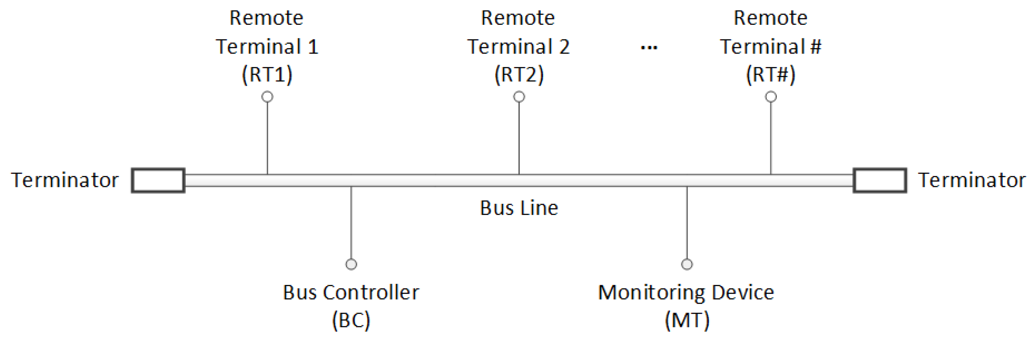
Figure 2.
The timing diagram of the data transmission with multiple message chains (MMCs) and the data processing in a RT with double buffers. The end-of-message (EOM) occurs whenever a message is transmitted from the BC to the RT. In the RT, the data processing for the current MMC in a buffer should be finished until the next MMC is received in the same buffer to avoid data loss.
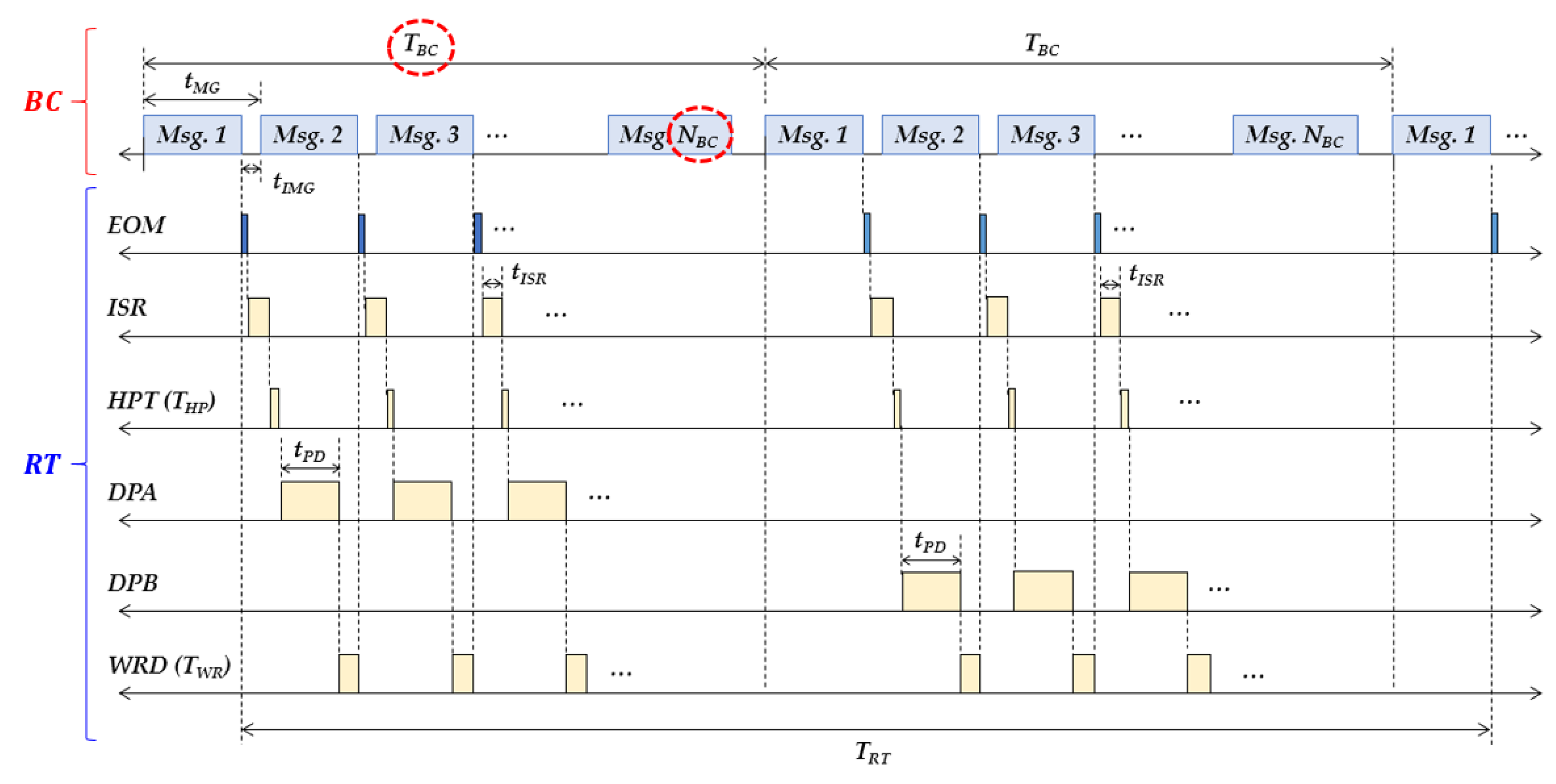
Figure 3.
The visualization of the objective values in the search space according to iterations in the Monte Carlo optimization (MCO). (a) Initialization; (b) intermediate iteration; (c) intermediate iteration; (d) final iteration.
Figure 3.
The visualization of the objective values in the search space according to iterations in the Monte Carlo optimization (MCO). (a) Initialization; (b) intermediate iteration; (c) intermediate iteration; (d) final iteration.
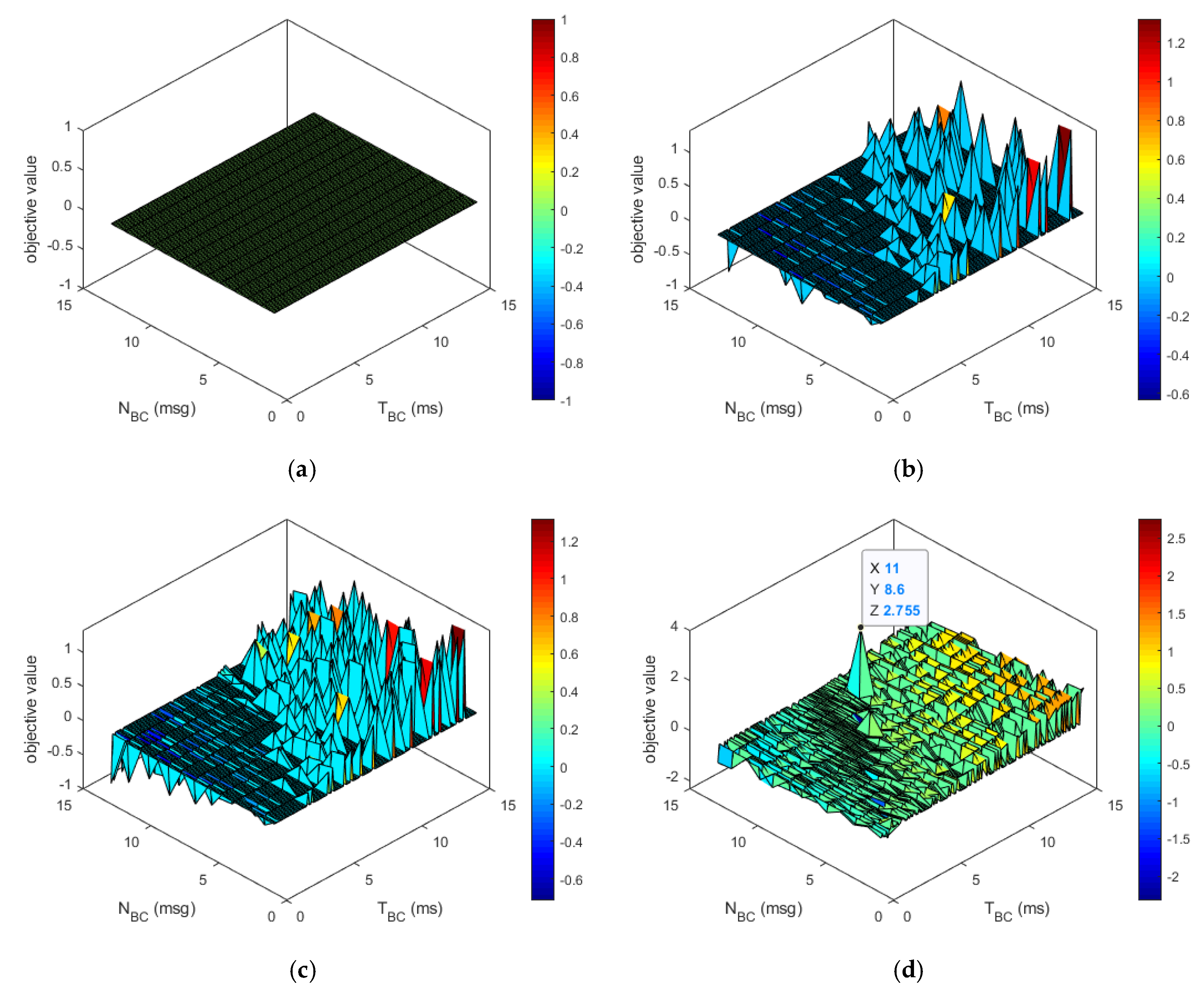
Figure 4.
The concept of the fixed-point vector definition in the field-programmable gate arrays (FPGA)-based real-time MCO (FRMCO).
Figure 4.
The concept of the fixed-point vector definition in the field-programmable gate arrays (FPGA)-based real-time MCO (FRMCO).
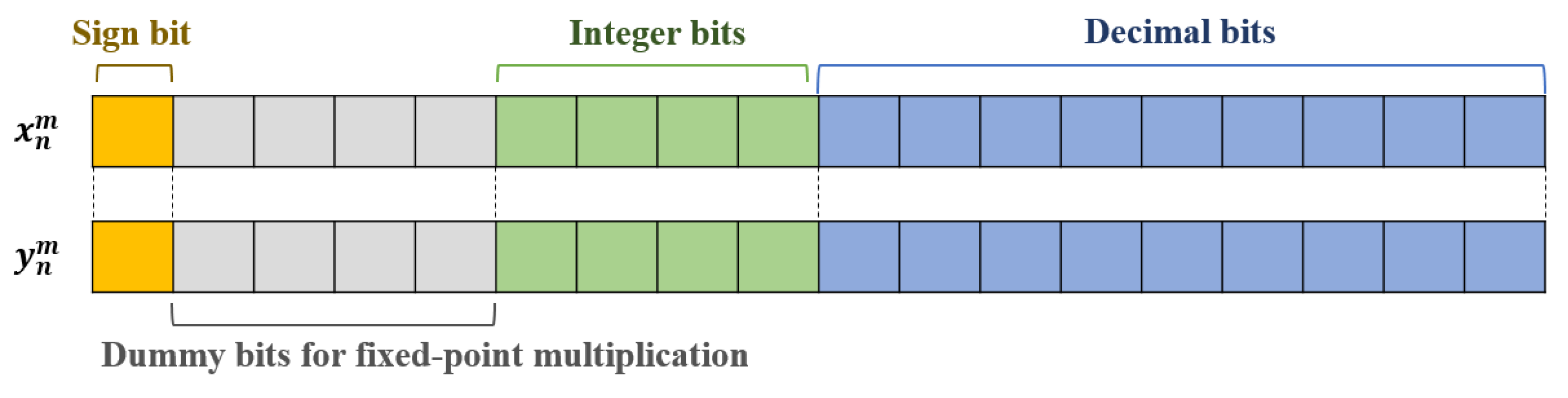
Figure 5.
The FPGA structure of the FRMCO which is the proposed method on FPGA.
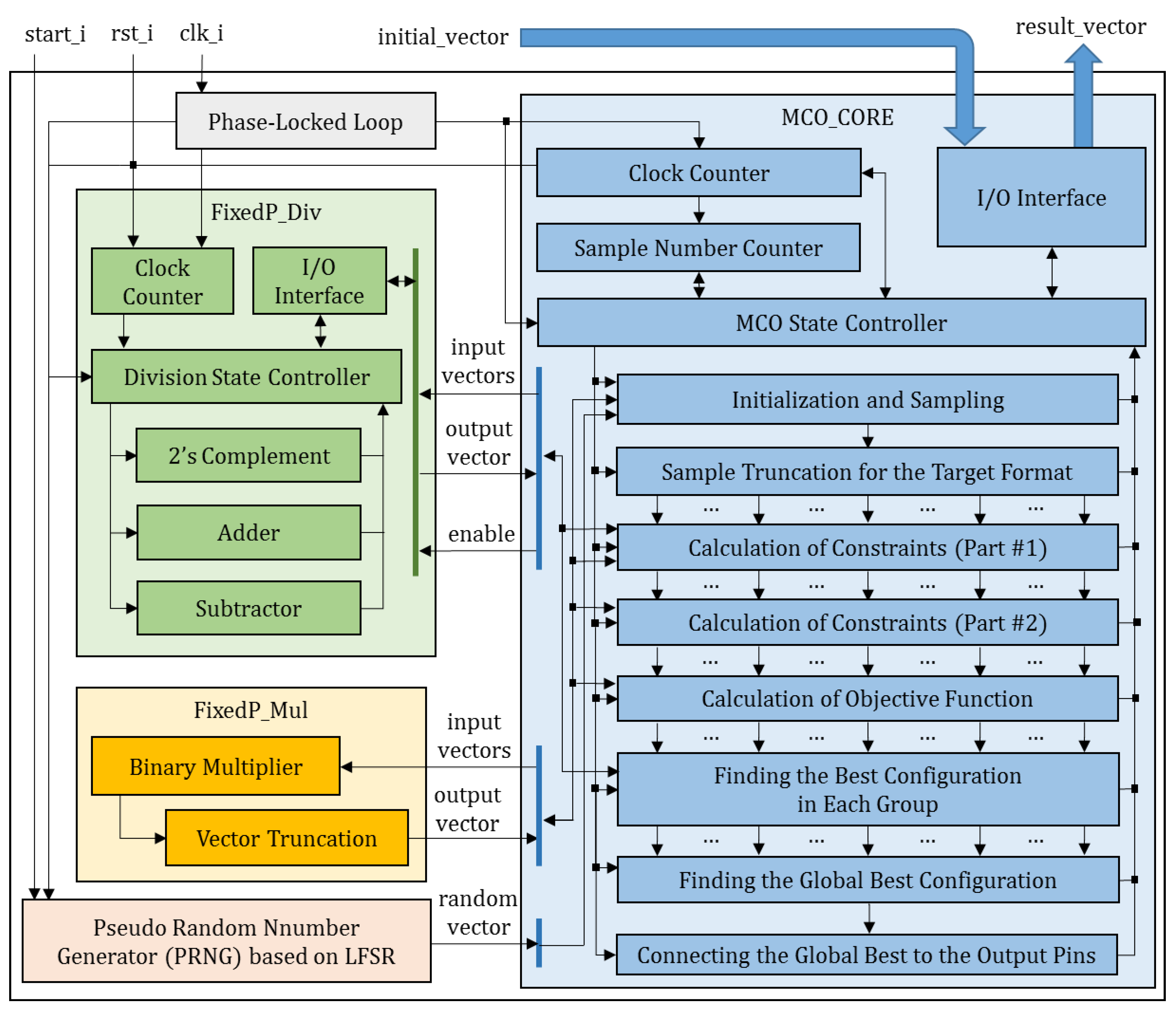
Figure 6.
The simulation result of the FRMCO with 500 samples in 20 groups when α = 0.
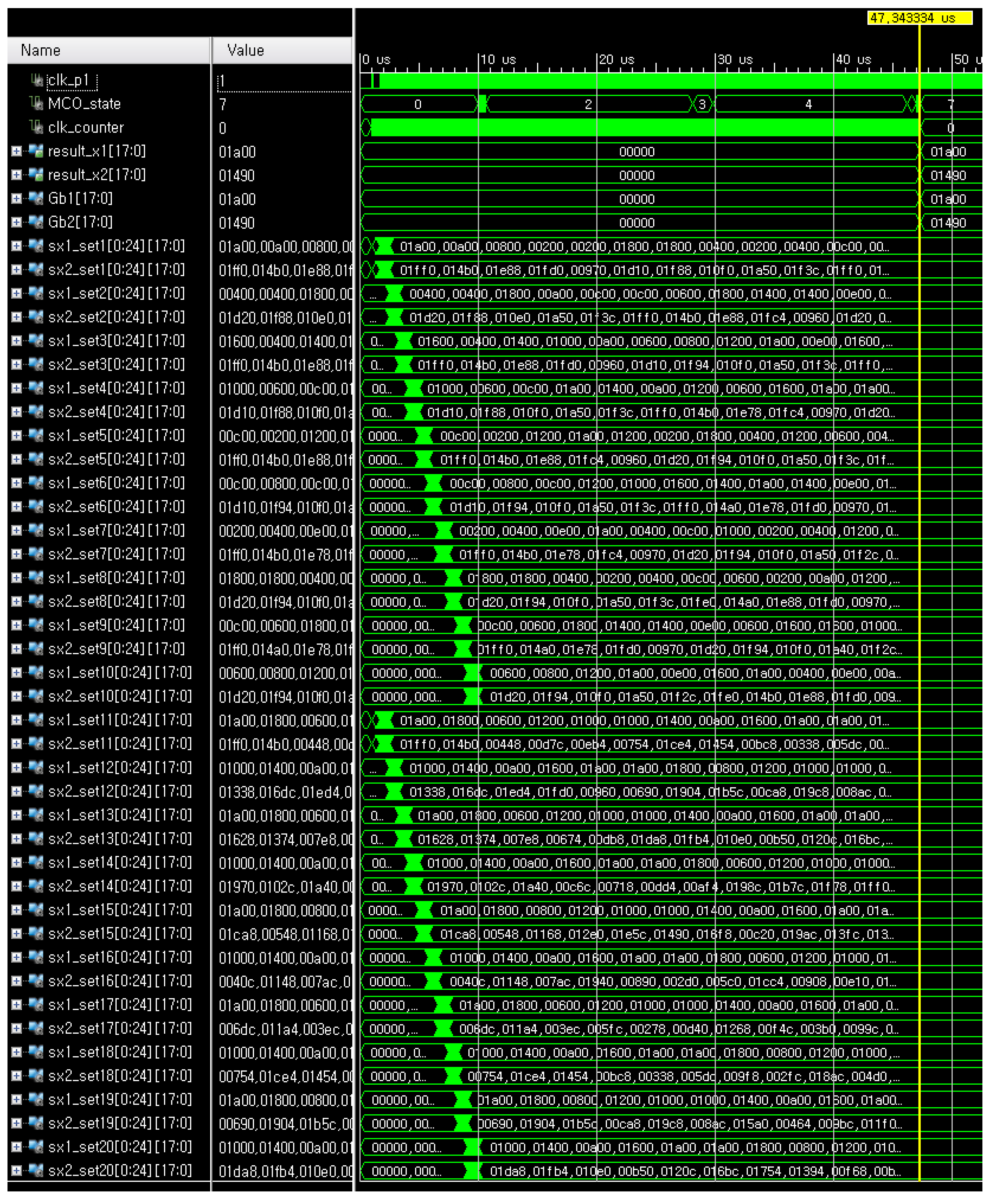
Figure 7.
The detailed simulation results of finding, respectively, the best group and the best configuration at the MCO_state 5 and 6 in the FRMCO with 500 samples in 20 groups when α = 0.
Figure 7.
The detailed simulation results of finding, respectively, the best group and the best configuration at the MCO_state 5 and 6 in the FRMCO with 500 samples in 20 groups when α = 0.

Figure 8.
The objective values in the search space at the final iteration of the FRMCO.
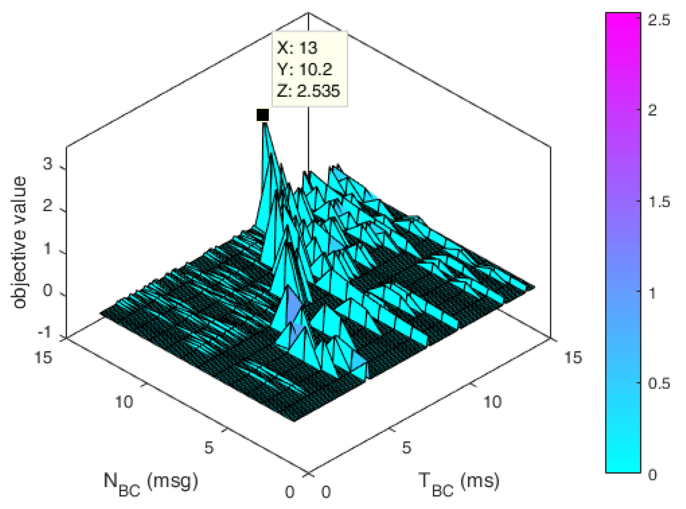
Figure 9.
Optimization results according to the design margin (α) with 500 samples in the FRMCO.
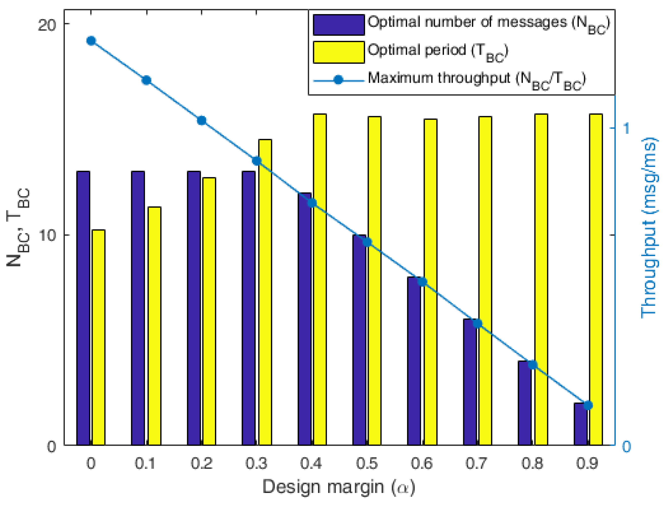
Figure 10.
The maximum data throughput results and the computation times according to .
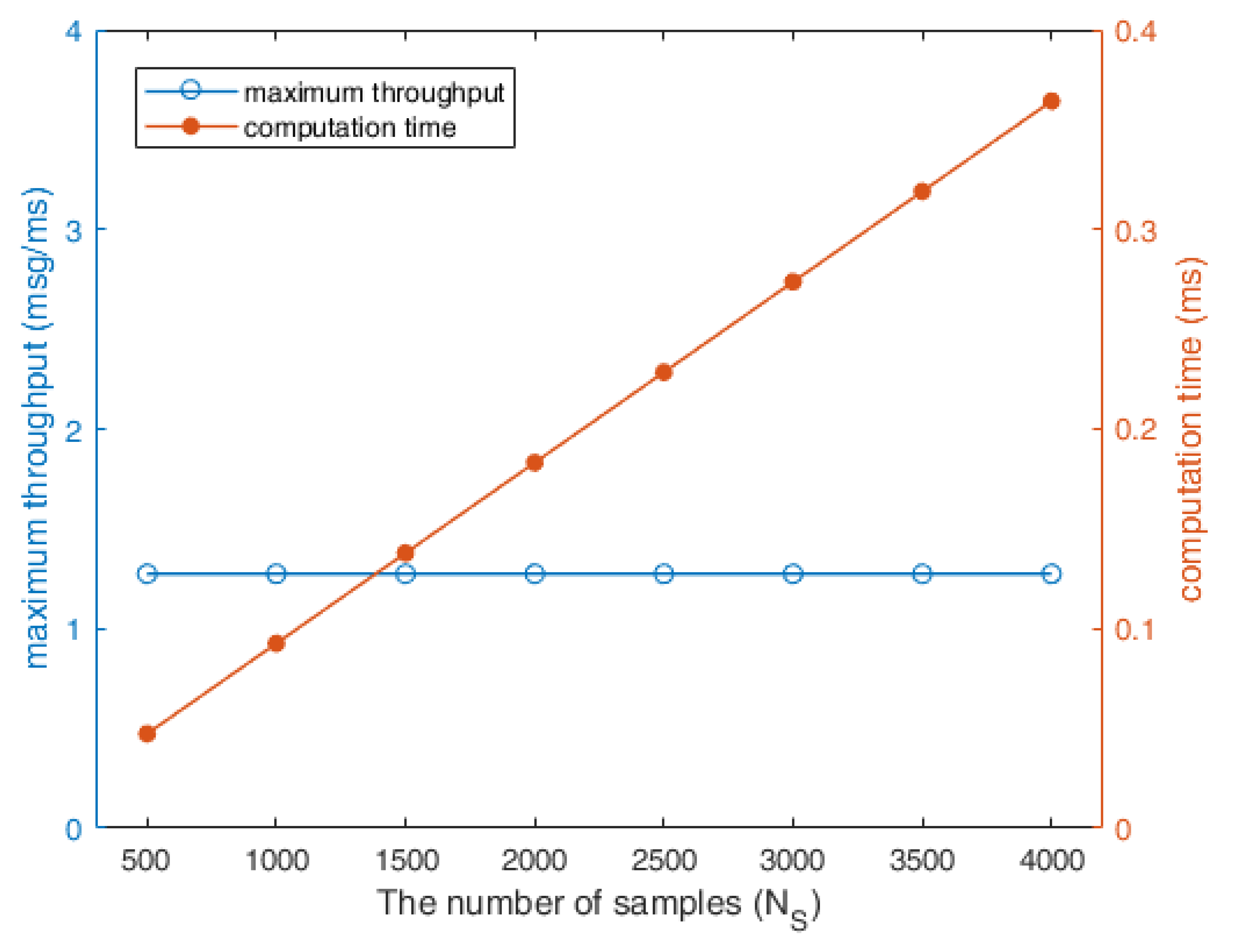
Figure 11.
The comparison of computation times between the conventional MCO and the FRMCO according to .
Figure 11.
The comparison of computation times between the conventional MCO and the FRMCO according to .

Figure 12.
The utilization results of the FRMCO according to .
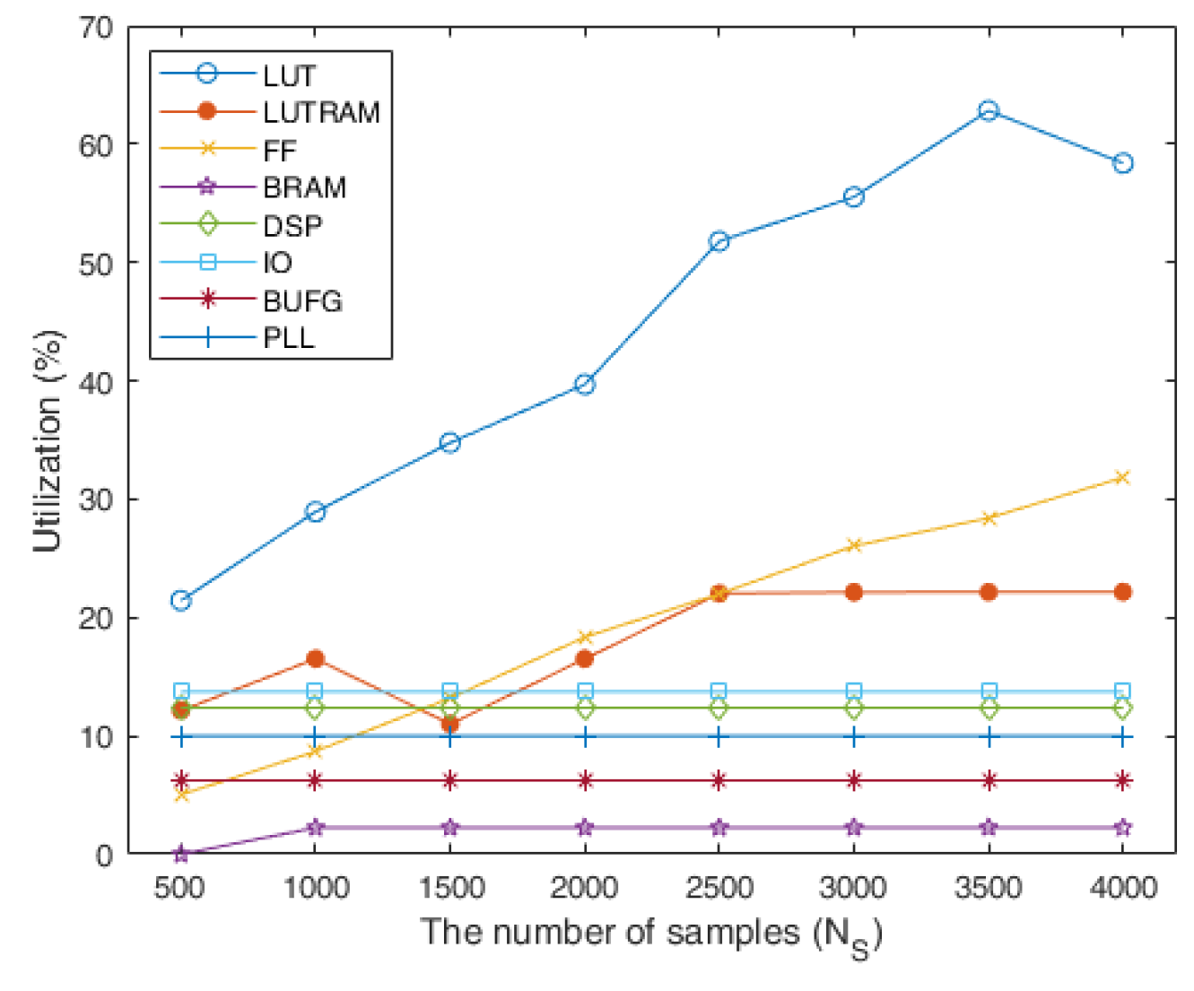
Figure 13.
The quantization errors for sample positions and objective values between the conventional MCO and the FRMCO with 500 samples.
Figure 13.
The quantization errors for sample positions and objective values between the conventional MCO and the FRMCO with 500 samples.

Table 1.
The main notations in this paper.
| Notation | Description |
|---|---|
| The number of messages in a message chain in the BC | |
| The transmission period of a message chain in the BC | |
| The whole required time in the RT | |
| Total writing time for responding messages in the RT | |
| Total processing time for the high-priority tasks in the RT | |
| Message gap time in the BC | |
| Processing time for the received message in the RT | |
| Processing time for an interrupt service routine in the RT | |
| The n-th sampled configuration in the m-th group | |
| The time constraint for the n-th sampled configuration in the m-th group | |
| The design margin constraint for the n-th sampled configuration in the m-th group | |
| The objective value for the n-th sampled configuration in the m-th group |
Table 2.
The main differences between the conventional MCO and the FRMCO.
| Type | Conventional MCO | FRMCO |
|---|---|---|
| Implementation | On CPU with C/C++ | On FPGA with HDL |
| Time step | Logical (OS-depend.) | Real system clock |
| Num. of states | Four | Eight |
| Operation | Generally sequential | Sequential and Parallel |
| Parallelizability | Depends on CPU cores | Depends on LUTs |
Table 3.
The utilization results of the postimplementation of the FRMCO with 500 samples in 20 groups.
Table 3.
The utilization results of the postimplementation of the FRMCO with 500 samples in 20 groups.
| Resource | Available | Utilization | Utilization (%) |
|---|---|---|---|
| LUT | 203,800 | 43,697 | 21.44 |
| LUTRAM | 64,000 | 7768 | 12.14 |
| FF | 407,600 | 20,521 | 5.03 |
| DSP | 840 | 104 | 12.38 |
| IO | 400 | 55 | 13.75 |
| BUFG | 32 | 2 | 6.25 |
| PLL | 10 | 1 | 10.00 |
Table 4.
The timing results of the postimplementation of the FRMCO with 500 samples in 20 groups.
| Type | Value |
|---|---|
| Total number of endpoints | 89,621 |
| The number of failing endpoints | 0 |
| Worst negative slack (WNS) | 1.085 ns |
| Total negative slack (TNS) | 0.000 ns |
| Worst hold slack (WHS) | 0.091 ns |
| Total hold slack (THS) | 0.000 ns |
| Total pulse width negative slack (TPWS) | 0.000 ns |
© 2019 by the authors. Licensee MDPI, Basel, Switzerland. This article is an open access article distributed under the terms and conditions of the Creative Commons Attribution (CC BY) license (http://creativecommons.org/licenses/by/4.0/).
Share and Cite
MDPI and ACS Style
Lee, H.; Kim, K. Real-Time Monte Carlo Optimization on FPGA for the Efficient and Reliable Message Chain Structure. Electronics 2019, 8, 866. https://doi.org/10.3390/electronics8080866
AMA Style
Lee H, Kim K. Real-Time Monte Carlo Optimization on FPGA for the Efficient and Reliable Message Chain Structure. Electronics. 2019; 8(8):866. https://doi.org/10.3390/electronics8080866
Chicago/Turabian StyleLee, Heoncheol, and Kipyo Kim. 2019. "Real-Time Monte Carlo Optimization on FPGA for the Efficient and Reliable Message Chain Structure" Electronics 8, no. 8: 866. https://doi.org/10.3390/electronics8080866
Note that from the first issue of 2016, this journal uses article numbers instead of page numbers. See further details here.