1. Introduction
With the further development of the 21st Century Maritime Silk Road, the marine economy and energy interconnection have become of key interest, which puts higher demands on energy security and power supply reliability. Compared with the mainland power supply, the special coastal environment of the coast makes the overhead lines subject to many restrictions, as a result, the submarine cable becomes the first choice for island power supply. Due to the special and complex marine environment, the safety operation and maintenance of submarine cables confronts great challenges. Due to the special and complex nature of the marine environment, the safety operation and maintenance of submarine cables is facing severe challenges. Setting warning signs, submarine cable monitoring and alarming, and improving the submarine cable manufacturing process are the main means of strengthening the protection of submarine cables. However, these methods are limited to monitoring and protection in areas above the sea surface. It is impossible to monitor the complex seabed conditions where the submarine cables are located [
1]. Aiming at this practical problem, an ideal solution is taking use of underwater robots to monitor the submarine cable and the seabed environment to achieve the protection of the submarine cable. In recent years, research on cable-inspecting robot fish has made great progress [
2], However, presently the power supply and data transmission of the underwater robot system is achieved by getting the robot fish out of water and electrically connecting it to the inspection ship, and the flexibility and safety thereof are still greatly limited. Therefore, in order to adapt to the complex seabed environment, the robotic fish cable-inspection system that can run autonomously without the inspection ship will have better practical value and application prospects [
3].
For battery-powered submarine cable-patrol robot fish, the replenishment of electrical energy and the transmission of inspection data are important. For the problem of electric energy replenishment, the traditional solution is to manually charge the robot when it comes up to the water surface after patrol, but this method has low timeliness and poor operability [
4]. In recent years, the rise of wireless power transmission technology has provided an ideal solution for the charging [
5,
6,
7]. Underwater wireless power transmission technology can transfer electrical energy to load devices in a non-electrical contact way. In this transmission mode, there is no electrical connection between the power transmitting end and the power receiving end, which solves the problems of electric leakage and short circuit caused by the traditional plugging and unplugging mode used under water, and achieves the safety and flexibility of the underwater device power supply [
8].
In terms of wireless charging of robot fish, there are few related researches at home and abroad. For the seabed environment mentioned in this paper and the wireless charging of robotic fish with high-speed data transmission requirements, the existing research cannot meet the demand [
9]. In respect of signal transmission, a lot of work have been done on wireless power and signal transmission. Literature [
10,
11] proposed a scheme for parallel transmission of energy and signals in an ECPT (electric-field coupled power transmission) system. Specifically, literature [
10] proposed the parallel transmission of energy and signal by adding additional signal transmission channels. Literature [
11] presented a parallel transmission method of energy and signal based on square wave carrier duty cycle modulation, which loads the signal into the energy channel for parallel transmission. Literature [
12,
13] proposed a parallel transmission scheme of energy and signal in an ICPT (inductively coupled power transfer) system, and introduced a scheme of modulating digital signals and then loading them onto energy coils for simultaneous transmission. In the seawater environment, data transmission is usually achieved by acoustic method [
14,
15]. In the submarine cable-inspection system, due to the high salinity seawater environment and the need to deal with two kinds of signals, which are the handshake communication signals between the robot fish and the charging platform, and a large amount of detection data collected by the robot fish, the solutions mentioned in the existing literature cannot meet this special demand regarding energy and data transmission.
Therefore, this paper proposes a wireless energy and data transmission composite topology based on magnetic coupling resonance technology for the problem of wireless charging and data transmission of the submarine cable-inspection robot fish. Through the time-sharing transmission of electric energy and data, the transmission processes of electric energy and data are not affected by each other, thereby effectively improving the stability and reliability of the system working process. In this paper, the system characteristics of this composite topology working in three modes are studied. The time-sharing multiplexing method for energy and signal wireless transmission and its mode switching strategy are proposed, which solves the problem of underwater wireless charging and communication of submarine cable-inspection robot fish.
2. Energy and Data Time-Sharing Transmission Scheme
The working scene of the robot fish based on the method described in the introduction is shown in
Figure 1.
It is docked on the platform of underwater wireless charging and data transmission after inspection of robot fish. The platform identifies the load by the resonant coil current magnitude, and sends a handshake command after identifying the load. The robot fish responds to the command and sends battery status information to the platform. After the platform and the robot fish shake hands successfully, the platform wirelessly charges them and the robot fish transmits the inspection data to the monitoring center on the shore through the platform after the charging is completed.
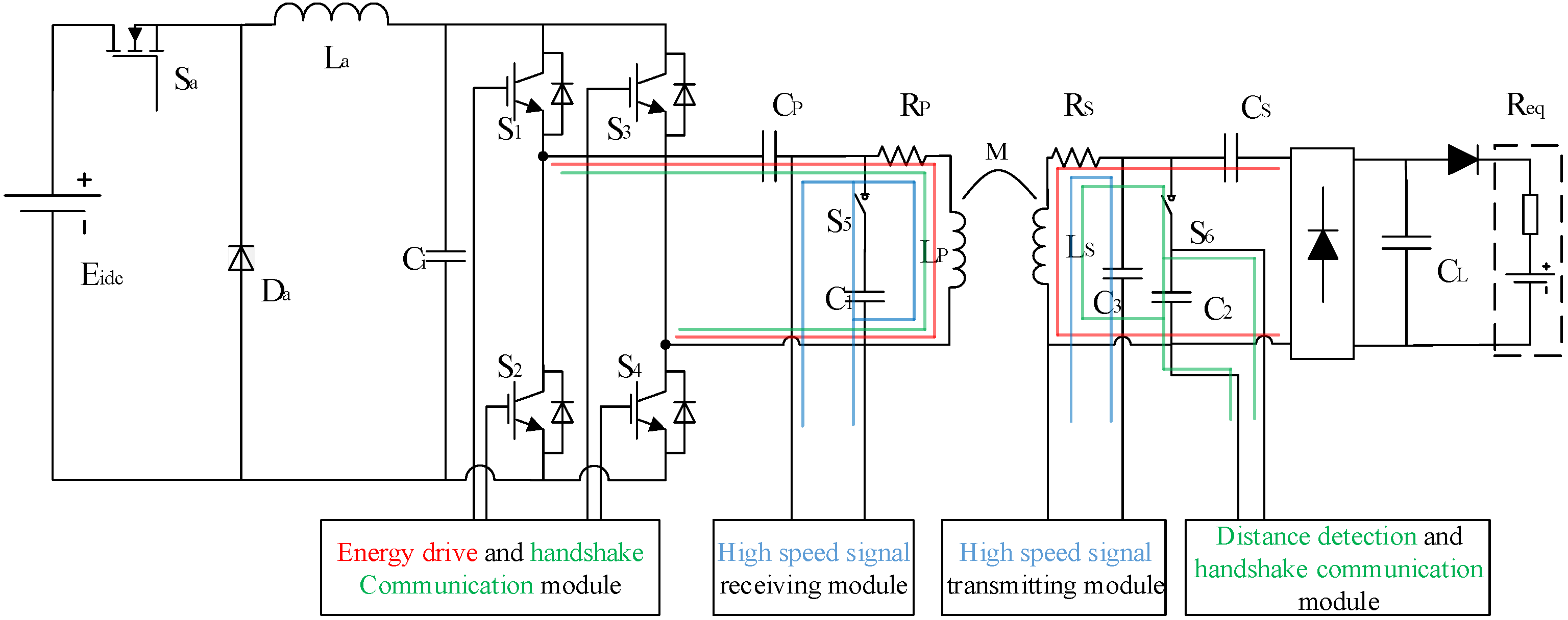
According to the wireless charging requirements of sea cable-inspection robot fish and its forward and reverse data transmission requirements, the structure of the energy and signal time division transmission system, as shown in
Figure 2, is proposed. As we can see in
Figure 2, the main topology consists of a BUCK converter, a full bridge inverter, a coupled reconfigurable resonant network, a rectifier, and the load. The BUCK converter regulates the transferred power by adjusting the input voltage of the inverter. The inverter converts the dc voltage into high frequency square wave ac voltage and stimulates wireless power transmission via the coupled resonant network. Then the rectifier converts the induced ac voltage into dc voltage and output to power the load. The coupled reconfigurable resonant network consists of a series–series (SS)-type network for power transfer (labeled by the red lines in
Figure 2), a series–parallel (SP)-type for distance detection and handshake communication (labeled by the green lines in
Figure 2), a SP-type network for high speed signal transmitting (labeled by the blue lines in
Figure 2), and the three networks can be configured by the switches S
5 and S
6.
In the scheme shown in
Figure 2, there are three modes of operation:
Mode 1 is the energy transmission mode, which is to achieve the wireless charging function of the charging platform to the robot fish. In this mode, the main circuit topology of the system is: BUCK + full bridge inverter + SS (primary side series compensation, secondary side series compensation) resonant network + rectifier + load (robot fish battery). The reconfigurable resonant network is configured as SS-type by turning off S
5 and S
6. Battery charging power is regulated by adjusting the duty cycle of the BUCK link switch S
a. The switching frequency of the full-bridge inverter link is the same as the resonant frequency
f0 of the SS resonant network, which can reduce switching losses and reduce EMI (electromagnetic interference) [
16,
17] in the soft-switching operation mode of the inverter switches.
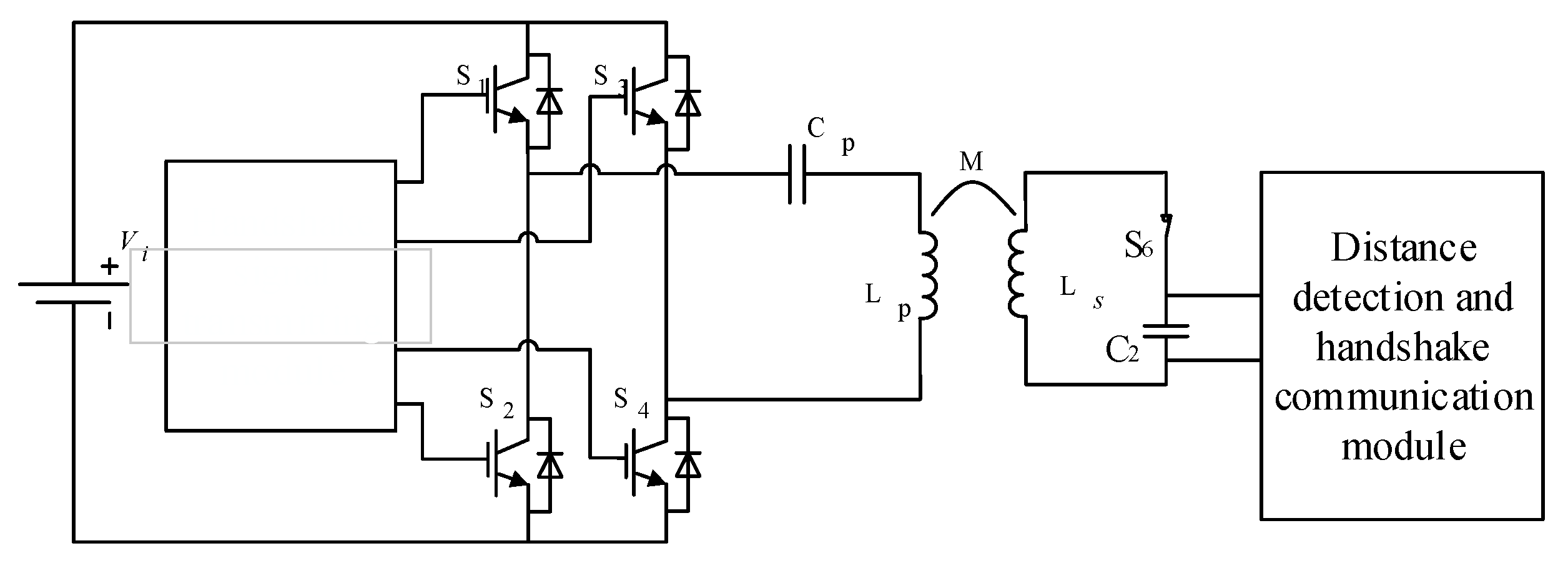
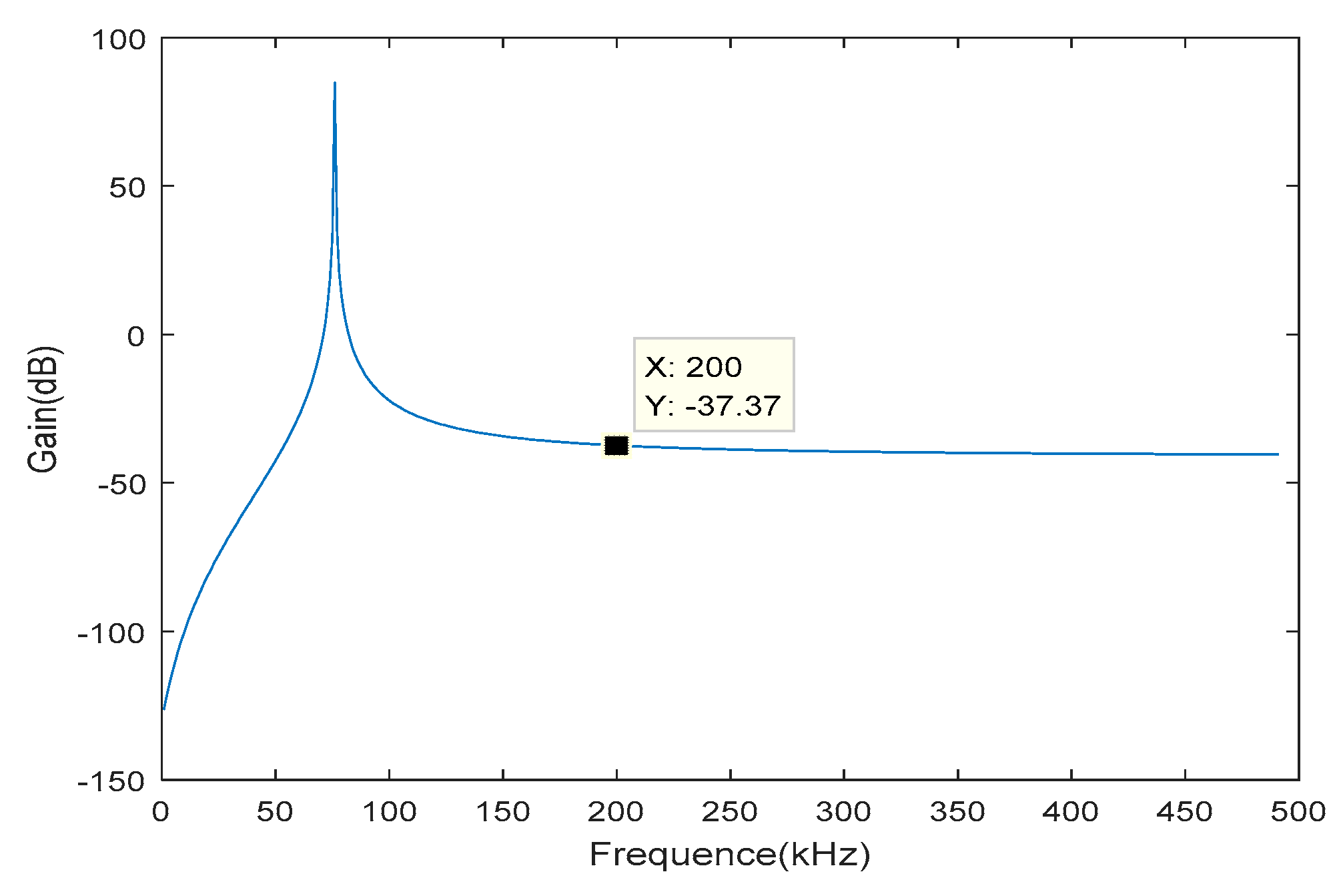
Mode 2 is an alignment detection and handshake communication mode, which is to complete the transmission and reception of the handshake signal from the charging platform to the robot fish, and the robot fish calculates the distance to the platform by recognizing the signal strength. The reconfigurable resonant network is configured as SP-type by turning off S5 and turning on S6. This mode uses ASK (amplitude shift keying) modulation to transmit data. The primary-to-secondary signal transmission modulates the digital signal with the inverter bridge control frequency f1 (f1>>f0), because the control frequency of the inverter bridge is much larger than the resonant soft switching frequency f0 of the resonant network, the system operates in a non-resonant state. Therefore, the transmission power is greatly reduced with a large loop impedance and achieves low-power data transmission. Because the resonant frequency (f0) of secondary side’s power transmission channel is much lower than the primary modulation frequency (f1), the pickup voltage will not be able to charge the battery after rectification and filtering, so that the series resonant circuit is in an open state and does not consume power. When the switch S6 of the signal receiving module is closed, the capacitor C2 and the inductance Ls of the pickup coil constitute a parallel resonant circuit, whose frequency is close to f1, so that a high signal voltage can be picked up. During the process of the robot fish approaching the charging platform, the amplitude of the picked-up signal gradually increases, and the robot fish can determine the offset distance to the platform based on the amplitude of the picked-up signal. When the amplitude of the picked-up signal reaches the maximum value, it indicates that the robot fish is directly above the charging platform, and then the robot fish can be controlled to park at the point. At the same time, the voltage can be demodulated by the signal demodulation circuit to demodulate the handshake signal sent by the charging platform. The robot fish can transmit a feedback signal to the platform by controlling the switch S6 to be on or off, and the platform demodulates the handshake signal from the envelope of the output current.
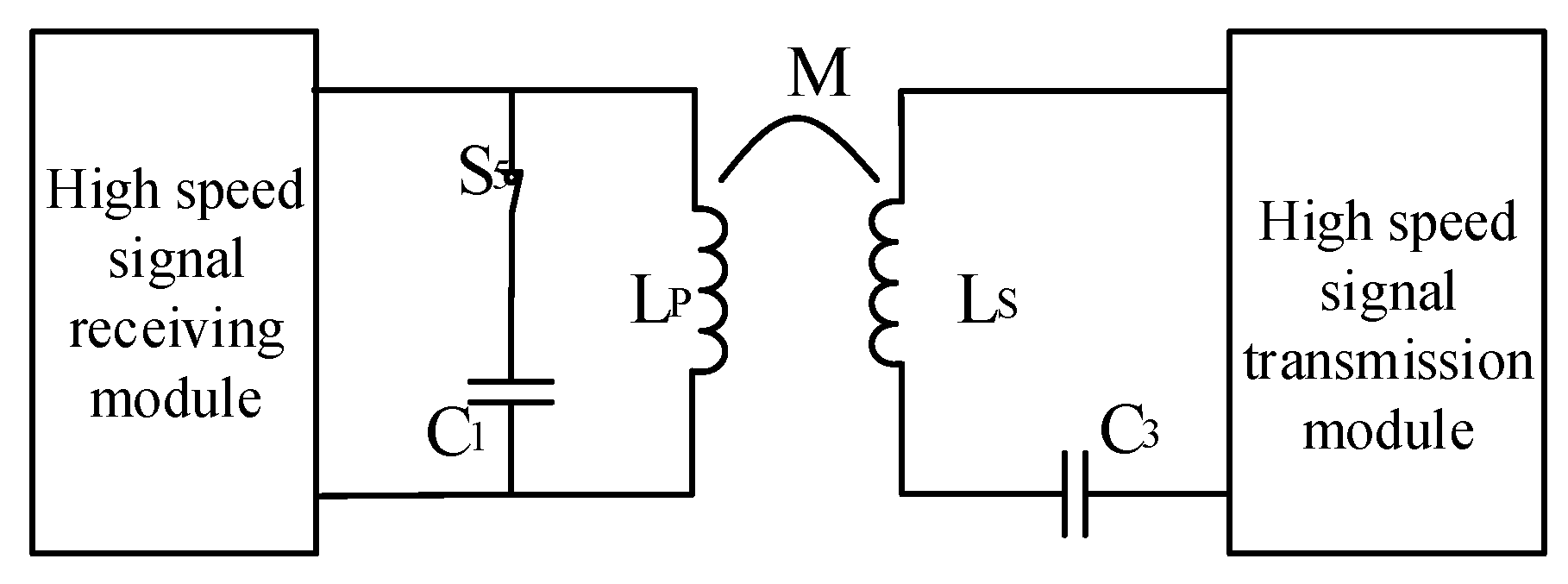
Mode 3 is a high-speed signal transmission mode, which is to complete the inspection data transmission from the robot fish to the charging platform. The reconfigurable resonant network is configured as SP-type by turning on S5 and turning off S6. Because the amount of inspection data is large, it is designed as a high-speed signal transmission channel based on OFDM (orthogonal frequency division multiplexing) mode. The data to be transmitted is loaded into the SP-type resonant transmission network composed of LS, C3, LP, and C1 through the signal modulation transmitting module. The signal secondary side demodulates the transmitted inspection data from the capacitance voltage signal of the P-type (parallel-type) pickup network.
As described above, the three working modes share the same coupled transmitting and receiving coils Lp and Ls. The system runs among the three working modes through a time-sharing multiplexing method to achieve accurate parking, high-efficiency wireless charging, and high-speed data transmission. Next, the characteristics of the three working modes will be analyzed and then the time-sharing multiplexing method for mode switching will be given.
4. Time-Sharing Multiplexing Strategy for Mode Switching
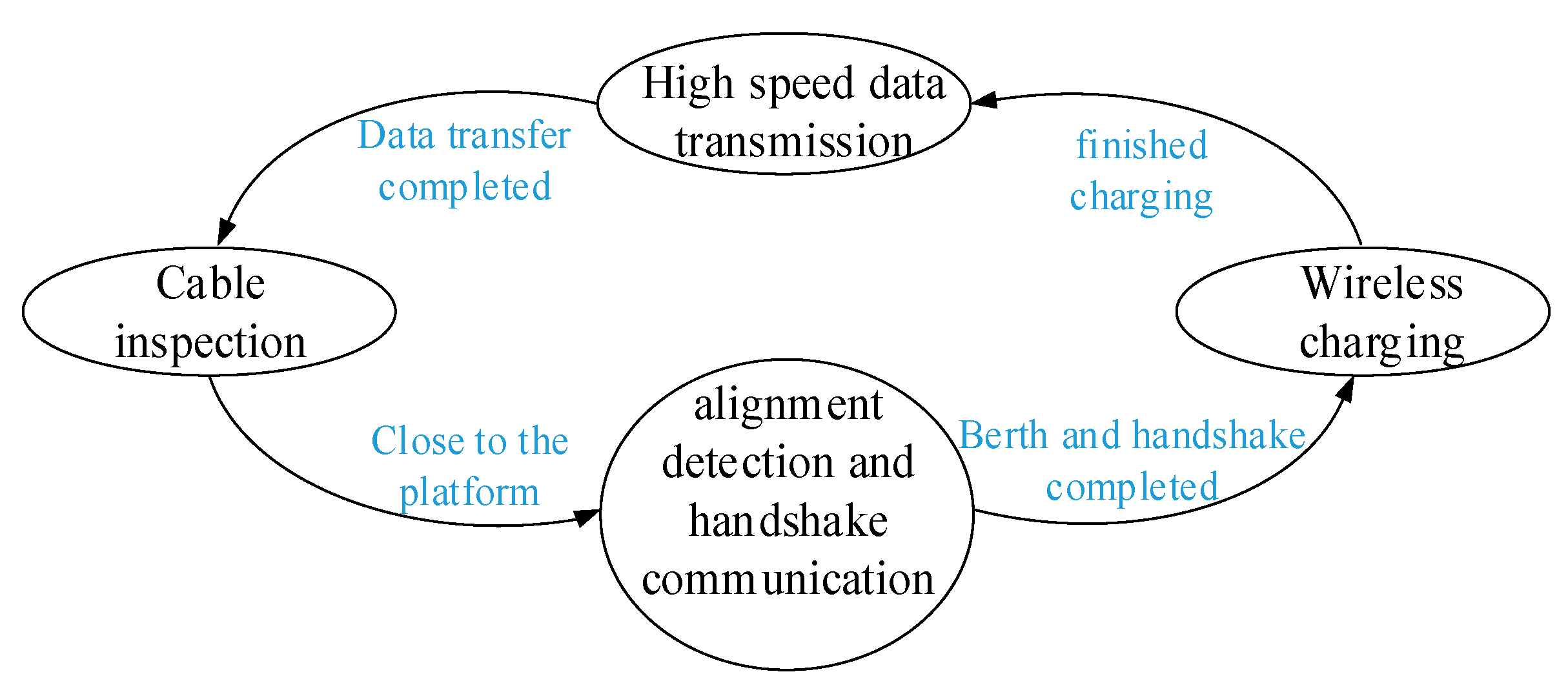
When the inspection robot fish returns to the charging platform, in order to carry out efficient and reliable power supply and data transmission, the time-sharing multiplexing strategy for mode switching between the three working modes is shown in
Figure 8.
In the stage of standby, the charging platform periodically adjusts the handshake signal with the robot fish by inverter bridge in the modulation mode of AFK, and waits for the robot fish to respond. During the process of the robot fish approaching the platform, the robot fish reaches the top of the charging platform and performs a berth at the maximum point of the signal amplitude by detecting the amplitude of the received signal to determine the alignment between the platform and the robot fish. After the robot fish’s berth is completed, the handshake signal sent by the platform is received and the feedback signal is modulated by the switching of switch S6. The charging platform demodulates the signal returned by the robot fish by detecting the change of the coil current, and enters the charging mode if the feedback signal is correct. During the charging process, the primary side collects current and voltage on the coil, and judges whether the charging is completed by calculating the equivalent impedance. After charging is completed, the robot fish enters the high-speed data transmission mode and transmits the submarine cable-inspection data packet. When all the data is sent, the charging platform checks whether the data is complete and sends a response. If the data is sent correctly, the robot fish enters the inspection state again, and the charging platform enters standby state.
The system workflow is shown in
Figure 9.
5. Experimental Study
In order to verify the feasibility of the wireless power and data transmission scheme of the shared channel mentioned above, the experimental device is built according to the system topology diagram shown in
Figure 2, and the system parameters are designed as shown in
Table 1 according to the parameter design method proposed in [
19,
20]. The power and data transmission performance and various indicators of the system are further verified by experiments.
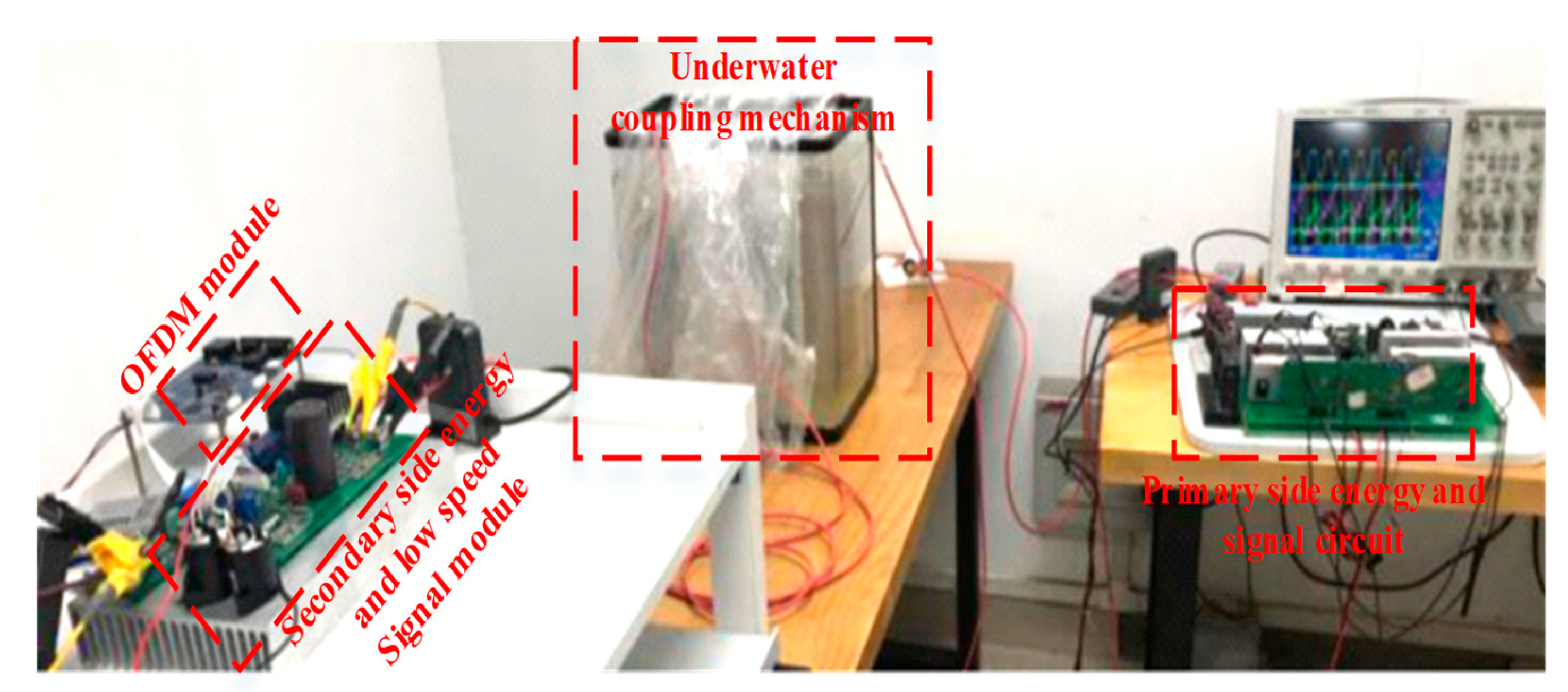
The experimental prototype diagram is shown in
Figure 10. The prototype includes power conversion, signal modulation and demodulation, coupling mechanism, and load composition. The power conversion part performs high-frequency inversion on the direct current and necessary overcurrent and overvoltage protection, realizes amplitude amplification by compensating the network, generates an alternating magnetic field on the resonant network, and transmits to the secondary side of the electric energy. The signal modulation and demodulation section complete the carrier signal modulation, the power amplification and the amplitude change of the carrier signal are shaped and restored to a digital signal to communicate with the host computer. The secondary side power conversion section provides rectification and voltage regulation functions to provide the DC power required for charging to the load.
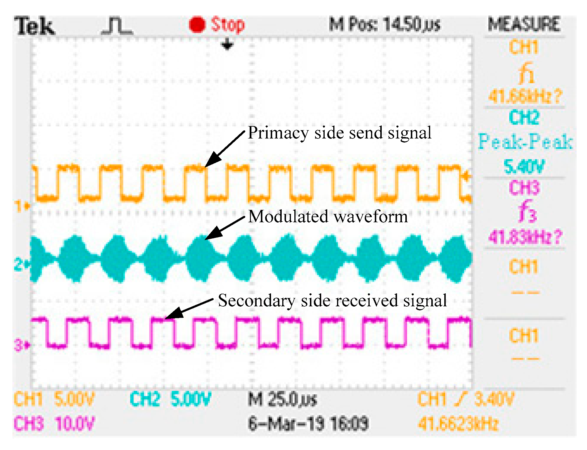
The experimental device handshake communication signal transmission part adopts half-duplex communication, and performs modulation and demodulation in ASK mode, the carrier frequency of the transmitted signal is 200 kHz. In order to make the working frequency and the signal carrier frequency of the power transmission mode far away from each other, the working frequency of the power transmission is designed to be a frequency of 85 kHz, which not only ensures the power transmission but also does not affect the communication effect. High-speed signal transmission uses a 2 to 28 MHz carrier OFDM module for high-speed data transmission from the robotic fish to the charging pile. The energy and signal transmission experimental waveforms are shown in
Figure 11,
Figure 12 and
Figure 13, where
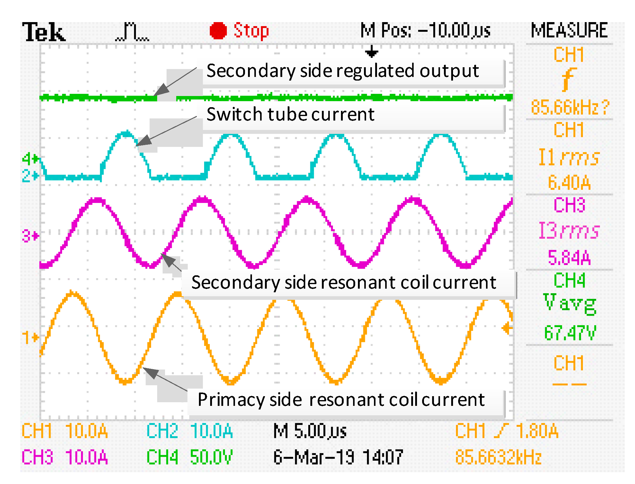
Figure 11 shows the working waveform of the coil voltage and current at the time of power transmission.
Figure 12 is a waveform diagram of a signal secondary side carrier signal and a demodulated signal during signal transmission.
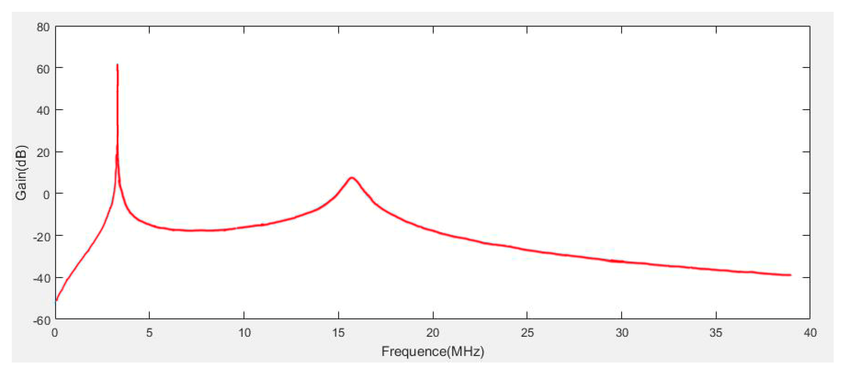
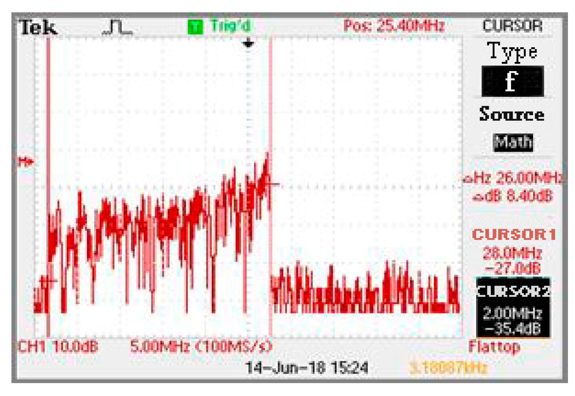
Figure 13 is a spectrum waveform obtained by fast Fourier transform of a picked-up signal in a high-speed signal transmission mode, which reflects the gain of each subcarrier in the OFDM modulation mode.
As it can be seen from
Figure 11, since the power transmission portion operates at the resonance frequency point of the system, the system operates in a resonance state. At the same time, the experimental device was used to test different loads. The system works stably, the transmission power reaches 300 W, and the efficiency is above 80%, which satisfies the wireless charging demand of the submarine patrol robot fish.
From
Figure 12, the ASK method can demodulate the digital signal very well. In the handshake communication signal transmission mode, the charging pile sends a control signal to the robot fish, the baud rate reaches 41 kbps, and the error rate of the system signal transmission is less than one ten thousandth. In practical applications, measures such as adding verification to signal transmission can ensure stable and reliable transmission of system signals, which can meet actual needs.
The high-speed signal transmission mode signal spectrum is shown in
Figure 13. The data carrier has a frequency band of 2 to 28 MHz and a frequency band of 26 MHz, which contains many subcarriers. The data transmission can be carried out steadily, and the transmission rate is maintained at 10 Mbps or more, which satisfies the need for high-speed transmission of patrol data.


