1. Introduction
The acronym, SCADA, stands for Supervisory Control And Data Acquisition. A SCADA system is a collection of both software and hardware components that allows for the supervision and control of plants and industrial processes both locally and remotely. The system involves the examination, collection, and processing of data in real time, as well as data logging for historical purposes. The architectural design of a standard SCADA system starts with Remote Terminal Units (RTUs), and/or Programmable Logic Controllers (PLCs). These RTUs and PLCs are micro-controllers or microprocessors that communicate and interact with Field Instrumentation Devices (FIDs) such as sensors, actuators, valves, pumps and transmitters. These communication data are routed from the controllers or processors via a SCADA Communication Channel to the SCADA computers known as Master Terminal Units (MTUs) where the data are interpreted and displayed on a Human Machine Interface (HMI) allowing operators and important decision makers to analyze and react to process events [
1,
2,
3,
4,
5].
SCADA technology has evolved over the past 30 years as a method of monitoring and controlling distributed processes [
5]. Before the emergence of SCADA, plant personnel had to monitor and control industrial processes via selector switches, push buttons, and dials (for analog signals), which meant that plants needed to maintain a good number of personnel on site during production to be able to carry out these manual monitoring and control tasks. As industrial processes grew and sites became more remote in nature, relays and timers were used to assist in the supervision and control of processes, which meant that fewer number of personnel were required on site to oversee their operations. While relays and timers provided a decent level of automation, they required more resources to manage their operations. The need to automate more processes, which coupled with the difficulties associated with the previous monitoring and control solutions gave birth to the first generation SCADA systems in the 1970s called Monolithic SCADA, and they were stand-alone units. With the advent of Local Area Network (LAN) and HMI softwares in the 1980s and 1990s, and with computer systems getting smaller and smarter, it became possible to connect SCADA systems to related systems which gave rise to the second generation SCADA called Distributed SCADA. Unfortunately then, the communications were typically proprietary which meant that the connections outside of the vendors of a particular SCADA system were not possible [
2,
3,
4].
Later in the 1990s and 2000s, SCADA began to implement open system architectures with communication protocols that were no longer vendor specific, leading to more connection capabilities in the form of a wide area network. This resulted in a more improved SCADA system called Networked SCADA system (3rd generation). With computer technologies growing rapidly, this SCADA was quickly out of date as other technologies were becoming more efficient and more in tune with the latest Information Technology (IT) developments. SCADA manufacturers had to rise to the challenge to come up with a SCADA architecture with great advantages over older SCADA systems. This is the Internet of Things SCADA architecture (4th generation) which incorporates cloud services with the conventional SCADA system for more robust monitoring and control [
6]. This SCADA allows for real-time plant information to be accessed from anywhere around the world using various operating systems and platforms [
2,
3,
7]. The Internet of Things (IoT) concept has to do with the connection of physical objects with embedded electronics, software, sensors and connectivity to enable data interchange between these devices and an operator over a common platform or the web [
6,
7,
8,
9,
10].
Presently, as in the past, automation companies such as Emerson, Siemens, Schneider Electric, and Allen Bradley develop various forms of SCADA hardware and software which they sell as turnkey solutions to end users. Examples of such solutions include Ovation SCADA communication server (Emerson), Simatic WinCC (Siemens), Clear SCADA server (Schneider Electric), and Micro SCADA (Allen Bradley) [
3,
11]. Currently, these systems come with various IoT-based MTUs for data visualization and process management such as the Totally Integrated Automation (TIA) portal in Siemens’ Simatic WinCC [
11]. In addition to the huge initial capital costs of buying these SCADA systems, which are in thousands of dollars, the end user is made to pay for annual maintenance and support fees to use the SCADA system solutions. For very large companies, like most companies in the Oil and Gas sectors, the costs of owning these commercial SCADA systems might be justifiable or affordable. However, for smaller companies with no enormous financial resources, but with the need to deploy SCADA solutions to monitor and control their distributed facilities, such as companies in the power sector or renewable generation systems, these commercial SCADA solutions do not represent a profitable choice. With the commercial systems, there is also the problem of interoperability with the existing infrastructures, for example power electronic converters in a power system [
12]. Seamless communication among devices in modern power systems is the key to successful SCADA implementation [
13,
14]. Therefore, a low-cost, open source SCADA solution represents the most viable solution [
4,
7,
12].
In this work, we propose a low-cost, open source SCADA system based on the most recent SCADA architecture, which is the Internet of Things [
6,
10,
15]. Our proposed SCADA system uses reliable and commonly available components to achieve the four basic functions of a SCADA system which the available commercial SCADA systems also perform: Data acquisition, networked data communication, data presentation, and remote monitoring and supervisory control [
1,
9].
The remainder of this paper is organized as follows. In
Section 2, we present the related works, problem statements, and the proposed SCADA system as a solution to the identified problems. In
Section 3, we present system descriptions, including the proposed SCADA system design configurations. In
Section 4, we present the components of the proposed SCADA system and the detailed description of each of the components.
Section 5 presents the implementation methodology,
Section 6 presents the prototype design,
Section 7 presents the experimental setup of the proposed SCADA system, and
Section 8 presents the testing carried out and the results. In
Section 9, the key features of the designed SCADA system are discussed, including the system cost and power consumption analysis. The paper is concluded in
Section 10, and future work presented in
Section 11.
2. Literature Review
The research communities all over the world have tried to solve the problems associated with commercial SCADA systems (high costs and compatibility issues) by developing various open source SCADA solutions, each with varying costs and functionalities. Rajkumar et al. [
16] have proposed a low-cost, open source SCADA system using Arduino Uno micro-controller as the sensor gateway, and ZigBee Radio Modules for data transmission from their field instrumentation devices such as flow sensors, temperature sensors, level sensors, control valves, and pumps to a data processing software, which they created with Java, where reports on the state of the process facility are generated and visualized. In [
17], a form of low-cost web-based SCADA solution is proposed. In this solution, Radio Frequency (RF) Receivers connected to a controller circuitry collect plant data, and the data are made available to the controller which, in turn parses the data to a driver circuitry for set point verification before the data get transmitted via the internet to a web-based SCADA server for visualization. The proposed solution here is complex as it involves the use of a mathematical model for data verification in the controller and driver circuitries before transmission to the web-based SCADA server.
Elsewhere, Merchan et al. [
18] implemented an open source SCADA system by using the general purpose programming platform, Python. Their proposed system is made up of three layers: a Device Layer, which is the process plant being managed, a Controller Layer, which comprises of two PLCs, and lastly, a Supervision Layer comprising of HMI SCADA client, and Python Open Platform Communications Unified Architecture (OPC-UA) Server with Structured Query Language (MySQL) Database, both installed in a Raspberry Pi3. Here, communication between the control devices is via Ethernet. This solution uses a lot of components which means more power consumption and less reliability of the resultant SCADA system. The authors in [
19] have implemented a form of open source SCADA system for the monitoring of the level and flow rate of water in a container by using the open source SCADA platform called OpenSCADA where HMIs are created for data visualization. The major issues here are that the OpenSCADA software is not entirely free as it requires user subscriptions, and the proposed solution involves a large amount of logical programming for accurate data acquisition and visualization in the OpenSCADA platform.
Similar to [
19], Avhad et al. [
20] have proposed a form of open source automation system using Vijeo Citect SCADA software as the MTU, AtMEGA 2560 micro-controller as the RTU for sensor data collection, and ModBus protocol as the communication channel between the MTU and the RTU. In another development, Mononen et al. [
21] proposed a low-cost open source SCADA system comprising of sensor network for data collection, and a microprocessor for data processing and transmission via UDP Ethernet frame to a cloud environment. The cloud environment is composed of virtual machines running user-defined algorithms in the cloud for accurate data processing and handling. Just like [
21], the authors in [
7] have developed a low-cost SCADA system based on IoT technology where the RTU is connected to the field devices through TCP/IP and supported on a NoSQL database. The functionalities of their developed system were evaluated using a traffic management process. The major problem with these systems is that they are complex systems which will be difficult for an ordinary end-user to use. Furthermore, the solution in [
21] is prone to errors as it requires a great deal of user-defined algorithms in the cloud.
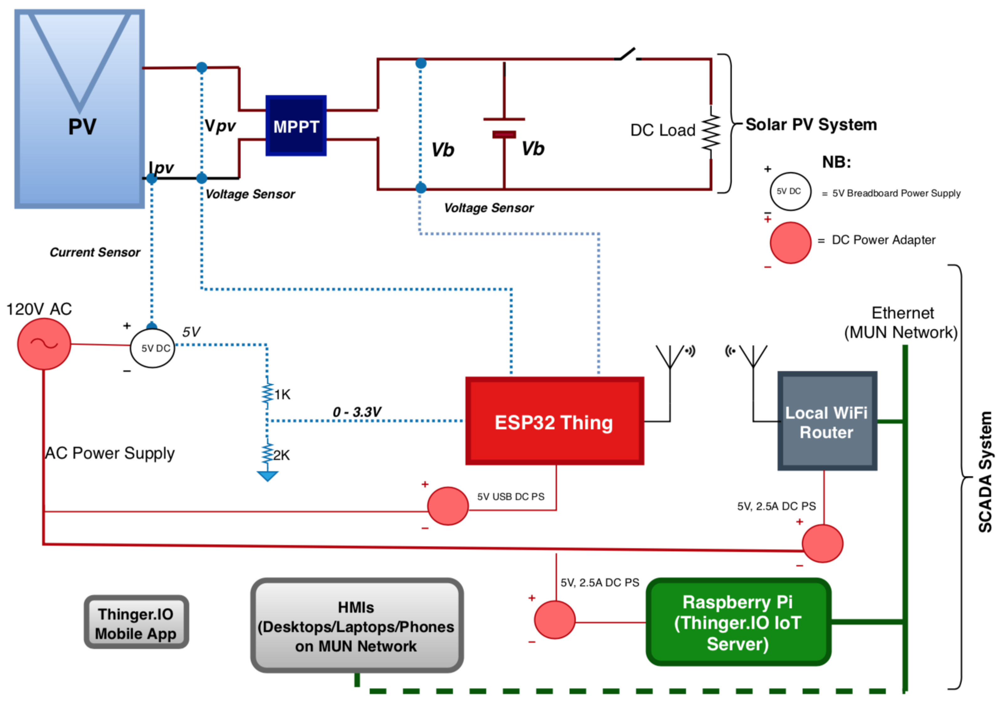
In this paper, we present the detailed design of a SCADA system using very few low-cost, low-power, and completely open source components. In our proposed SCADA solution, a locally installed Thinger.IO Server IoT Platform serves as the Master Terminal Unit where HMIs are created for data visualization and processing, and the versatile Sparkfun ESP32 Thing micro-controller serves as the Remote Terminal Unit for receiving and sending the sensor data from the Field Instrumentation Devices (sensors), while a local Wi-Fi Network provides the Communication Channel between the MTU and the RTU, resulting in a form of industrial network as implemented by the commercial SCADA vendors all over the world [
3,
9,
11].
The authors in [
22,
23,
24] have used Thinger.IO to implement their respective remote monitoring and automation systems. In their systems, the acquired sensor data are sent to Thinger.IO cloud platform where HMI dashboards are created for data visualization. In [
22], the visualized data are used for smart home energy decisions, while the acquired data in [
23] are used for RESTful motion detection where the operator is notified of process changes via the Thinger.IO platform. The implemented system in [
24] is a smart emergency response system using the powerful IoT properties of the Thinger.IO platform. Unlike our work where a locally installed Thinger.IO IoT server is used, these authors have used the web-based Thinger.IO platform requiring the public internet for access which means that the resulting monitoring solutions are vulnerable to internet attacks. Security in a SCADA system is a serious issue as attacks on a SCADA system can compromise the critical process facilities being managed [
4,
9,
25,
26]. To ensure the security of a SCADA system, several techniques can be used. Some of these techniques include a security technique focused on the communication channel or network as discussed in [
27,
28,
29], a technique focused on protecting the hardware components as in [
30], and a data-driven technique focused on protecting the cloud server as discussed in [
6,
25,
31,
32], or a combination of two or more of these techniques [
27,
33]. The SCADA system proposed in this work considers a combination of some of these security techniques, including the private network management and the data-driven private cloud server management techniques. Here, because the main cloud server is locally hosted on Memorial University (MUN) network, the operator has full control of the security of the system and can take several measures to protect the data in the cloud, such as ensuring access control, whitelists, authentication, authorization, firewalls, regular risk assessment, continuous monitoring and log analysis, updating and patching regularly, etc. [
6,
15,
25,
28]. This is why we propose a locally installed Thinger.IO IoT server in this work, and to the best of our knowledge from reviewed literatures, and related works, we have not found a SCADA system solution where a locally installed Thinger.IO IoT server has been used.
It should be noted that the SCADA system solution presented in this paper is similar in functionalities to our previous open source IoT-based SCADA system [
9], where we used a locally installed EMONCMS IoT server as the Master Terminal Unit, and Arduino Uno and Raspberry Pi as the RTUs to receive sensor data, with Node-RED flows, which used Ethernet for communication, serving as the Communication Channel between the MTU and the RTUs. However, as the components and the design and implementation methodologies used in both systems are totally different, the work presented here is not a continuation of our previous work but rather a different open source SCADA system solution meant to tackle the shortcomings in the available commercial SCADA systems, and the reviewed open source SCADA system solutions. Also, in our previous open source SCADA system solution, more components were used which meant more difficulty in implementation and usage, more power consumption, less reliability, and more cost. Furthermore, unlike our previous SCADA system solution where a single configuration was considered, two configurations are tested and presented in this current work. The first configuration is one in which data on the Thinger.IO IoT platform are accessible over the internet as long as the user is within the Memorial University network and has the authorizations to connect to the network. In this case, the Raspberry Pi micro-controller hosting the Thinger.IO IoT Server is connected to MUN Network using an RJ45 Ethernet cable. The second configuration is such that only the users connected to the locally created Wi-Fi Network (this connection is either wireless or via network cables to the LAN ports of the Wi-Fi Router) can connect to the Thinger.IO IoT platform for data visualization, remote monitoring and supervisory control. This second configuration creates a form of industrial network which is only accessible to authorized users on the network. In either configurations, the proposed SCADA system solution here will help to tackle the mentioned setbacks in the systems presented in literatures, high cost and compatibility issues in the available commercial SCADA systems, and the minor setbacks in our previous SCADA system solution by using fewer components which are known to consume less power, and are less expensive, while ensuring the same robust SCADA functionalities as in both our previous work and the available commercial SCADA system solutions.
The rest of this paper is dedicated to the system and components descriptions, implementation methodology, prototype design, experimental setup and testing of the proposed low-cost, open source IoT-based SCADA system solution.
4. Components of the Proposed SCADA System
The SCADA system proposed in this work is made up of analog voltage and current sensors for data acquisition, SparkFun ESP32 Thing micro-controller for receiving, processing and parsing the sensor data, Wi-Fi Router for local Wi-Fi network creation (communication channel), and Thinger.IO local IoT server with graphical user interface (dashboards) created for remote sensor data monitoring and supervisory control. Each of these components is described in details below:
4.1. Sensors
Sensors are the Field Instrumentation Devices in the proposed SCADA system as they are connected directly to the PV system being managed to acquire the desired data [
1,
34]. Three analog sensors are used in our setup; one ACS 712 Hall Effect Current Sensor, and two MH Electronic Voltage Sensor modules. The operating signal voltage (VCC) of the current sensor is 5 V single supply, and that of voltage sensor is between 3.3 V to 5 V, while that of the ESP32 Thing micro-controller is 0 V to 3.3 V. This means that the current sensor is not suitable for direct connection to the analog-to-digital converter (ADC) Pins of the ESP32 Thing. Therefore, in order to ensure that the sensor matches the 3.3 V signal voltage of the ESP32 Thing, some level shifting is carried out by using a pull-down or step-down resistor arrangement (
Figure 3). This will ensure the accuracy of the measured sensor value. The properties of these sensors and their usage in this work are described below:
4.1.1. ACS 712 Hall Effect Current Sensor
The ACS 712 Hall Effect Current Sensor, manufactured and supplied by Allegro MicroSystems, LLC. is a low-cost, fully integrated, Hall Effect-based linear current sensor IC with 2.1 kVRMS Isolation and a low-resistance current conductor. It has a low-noise analog signal path, 5 V single supply operation, 66 to 185 mV/A output sensitivity, and nearly zero magnetic hysteresis. In its operation, the applied current flowing through the copper conduction path generates a magnetic field which the Hall IC converts into a proportional output voltage [
35]. The output voltage is proportional to the AC or DC currents being measured [
35]. In this project, the 30 A module is used to measure the DC current from the solar PV system. This module is able to measure current values from 0 A to 30 A. Also, with this module, 0 A corresponds to 2.5 V, while 30 A corresponds to 5 V. These parameters, as well as the parameters of the ESP32 Thing ADC Pins are taken into consideration in writing the ESP32-Arduino code to measure the PV current with the sensor. With respect to the physical connections, the pull-down or step-down resistors arrangement described in “Sensors” above is used to match the 5V signal requirement of the Current Sensor to the 3.3 V signal capability of the ESP32 Thing ADC Pins. The step-down resistors arrangement showing the connection of the sensor to the ESP32 Thing is shown in
Figure 3, and the voltage divider equation is shown in Equation (
1). As can be seen, it’s VCC pin is powered with the 5 V supply from the Breadboard, the OUT pin is connected via the pull-down resistors to the Analog pin 32 on the ESP32 Thing micro-controller, and its ground (GND) pin is connected to the GND pin on the Breadboard while the two Input pins are connected in series to the PV system to measure the DC current flowing through the system.
where
= ESP32 ADC Voltage (3.3 V), and
= Sensor Input Voltage from the Breadboard (5 V), while and
and
are calculated to match these voltage values using the voltage divider equation above.
4.1.2. MH Electronic Voltage Sensor Modules
This is a low-cost analog voltage sensor capable of detecting supply voltages in the range of 0.025 V to 25 V. The sensor uses the concept of voltage divider to measure voltage. This voltage divider is a series connection of a 30 K resistor and a 7.5 K resistor. Its operating voltage range is 3.3 V to 5.0 V, and the voltage analog resolution is 0.000806 V for a 12-bit ADC [
36]. In our setup, two voltage sensors are used; one of the voltage sensors is connected in parallel to the PV system to measure the voltage across it while the second one is connected in parallel across the lead acid battery system to measure the storage battery voltage. For the first voltage sensor, PIN S is connected to Analog PIN 34 on the ESP32, PIN—is connected to a GND pin on the ESP32 while its GND and VCC pins are connected in parallel across the PV panel output to measure the voltage across the PV system (PIN + on the sensor is not used). For the second voltage sensor, PIN S is connected to Analog PIN 35 on the ESP32, PIN—is connected to a GND pin on the ESP32 while its GND and VCC pins are connected (after the MPPT module) in parallel across the battery to measure the battery voltage (PIN + on the sensor is not used).
4.2. ESP32 Thing Micro-Controller (RTU)
The ESP32 Thing, manufactured and supplied by SparkFun Electronics, is a comprehensive development platform. It is a Wi-Fi compatible micro-controller, it supports Bluetooth Low-Energy (i.e., BLE, BT4.0, Bluetooth Smart), and it has nearly 30 Input/Output (I/O) pins [
37]. According to the manufacturer, it is called the “Thing” because it is the perfect foundation for Internet of Things projects [
37]. It is one of the most unique low-cost (about
$20 CAD), low-power (about 0.5 W) micro-controllers available on the market today. The board can be powered with either a 5 V USB power supply or with a single-cell lithium-polymer (LiPo) battery, and its operating signal voltage range is 2.2 V to 3.6 V. The I/O pins of the ESP32 Thing board are only 3.3 V tolerant, hence the need for the level shifting of the connected 5 V current sensor explained earlier.
Figure 4 shows a picture of the SparkFun ESP32 board while
Figure 5 shows a summary of the hardware specifications of the board [
37].
The ESP32 Thing micro-controller is programmed with an Arduino software integrated development environment (IDE). The Arduino IDE allows one to write the desired programs and upload them to the board via a USB cable. Arduino programs are called Sketches, and its language is merely a set of C/C++ functions [
37]. In this project, the ESP32 Thing is hooked to a Breadboard, and the current and voltage sensors are connected to it as described in the “Sensors” section above. First, an Arduino sketch to measure the voltage and DC current from the PV system, and calculate the PV power output from the voltage and current values, as well as to separately measure the storage battery voltage via the sensors is written in the Arduino IDE and uploaded to the board. The measured and calculated values are displayed on the Serial Monitor of the Arduino IDE using the specified Baud Rate. Secondly, having uploaded the program (sketch) into the ESP32 Thing board, the board is powered with a 5 V USB power cable.
4.3. Raspberry Pi Micro-Controller
The Raspberry Pi 2 model B used in this project is a 85 × 56 mm single board computer (micro-computer) device with BCM2836 quad core (4 processors in one chip) ARMv7 processor. It is a low-cost chip and it has the following properties which make it robust and suitable for the proposed SCADA system design [
38,
39]:
A 900MHz quad-core ARM Cortex-A7 CPU
1GB RAM
One hundred Base Ethernet
Four USB ports
Forty GPIO pins
Full HDMI port
Combined 3.5 mm audio jack and composite video
Camera interface (CSI)
Display interface (DSI)
Micro SD card slot
VideoCore IV 3D graphics core.
In this work, the Thinger.IO IoT Server is installed and configured on the Raspberry Pi and the Raspberry Pi is connected to the other components in either of the two configurations described earlier.
Wi-Fi Router (Communication Channel)
In the proposed SCADA system, Wi-Fi serves as the communication channel between the ESP32 Thing (RTU), and the Thinger.IO IoT Server (MTU). This local Wi-Fi network is created using a D-Link Router (DI-524 Airplus G). It is a high speed router with 54 Mbps data transfer rate, 802.11b/g wireless protocol, and it is IEEE 802.11 standards compliant. The router has one WAN port and four LAN ports, and its operating frequency band is 2.4 GHz. Since the ESP32 Thing can implement TCP/IP, full 802.11b/g/e/i WLAN MAC protocol and Wi-Fi direct, the router is configured to setup the needed local Wi-Fi network for transmitting the sensor data from the ESP32 Thing to the Thinger.IO IoT Server by using the server IP address to identify the platform. For the Wi-Fi access control and security purposes, the ESP32 Thing connects to the router using the Wi-Fi network name (SSID) and the assigned password.
4.4. Thinger.IO Local Server IoT Platform
Thinger.IO is a powerful open source platform for the Internet of Things (IoT). It supports Representational State Transfer (REST) Application Programming Interface (API) which enables controlling and reading of smart devices [
40]. Representational State Transfer (REST) is an architecture based on web standards which uses HTTP protocol for communication. This protocol enables interoperability among the different machines on the internet by treating each and every component as a resource, such that each resource can be accessed by a common interface utilizing the general HTTP methods like OPTIONS, GET, PUT, POST, and DELETE, etc., [
22,
23,
24,
40]. The specific response of each resource is gotten in JSON/XML format [
40]. Some of the important features of the protocol which make it possible to connect and manage IoT devices are automatic discovery of API, and bandwidth savings [
24]. Thinger.IO is wholly supported by GitHub (the popular open source development platform) [
40].
Thinger.IO IoT platform supports the integration of Arduino compatible hardware (any board that can be programmed with Arduino IDE, such as Arduino + Ethernet, Arduino + Wi-Fi, ESP32/8266/13, NodeMCU, TC CC320, etc.), Linux-powered devices like the Raspberry Pi, Intel Edison or any other Linux computer running Ubuntu or MacOS, and the ARM Mbed platform and compatible devices. The IoT platform has a Cloud Console with a beautifully designed front-end where a user can manage the connected devices and visualize the device information in the cloud [
40]. To start an IoT project in Thinger.IO, the first step is to create devices by adding the device parameters which will grant access to connect the devices to the Thinger.IO account. Any device on the platform must be registered to have access to the cloud, and each device is identified by its unique identifier and credentials, such that an infinite number of devices can be added to the cloud platform without one device interfering with the other (Figure 7). Once a user creates an account on the Thinger.IO cloud, access token is obtained from the user’s Username and Password, and this access token grants authorization access to the account resources of the connected devices. On the Cloud Console is a Statistics section where a user can see some basic information about the account such as the number of connected devices, endpoints, data buckets, statistics about device consumption in terms of sent and received data, as well as a Google Map of the approximate current locations of the connected devices (Figure 12). In the Cloud Console, an operator can add or remove devices, create real-time dashboards, access the device API, and perform other device and data management operations [
22,
23,
24,
40]. Also, the left side of the Statistics screen has a main menu with all the platform features needed to build IoT projects (
Figure 6) [
40].
One unique feature of the Thinger.IO IoT platform is that it allows an operator to discover the resources defined in the connected devices. A resource, in this case, can be a sensor reading like current, voltage, temperature, humidity, pressure, or any actionable element like a light, a relay, a motor, etc. Once a device is connected to an account, an operator can access its resources and explore the API REST endpoints using the API Explorer which is accessible over the Device Dashboard by clicking on a small blue button called Device API (
Figure 6). Essentially, any device resource is like a callback function that can be called (on demand) through a REST API. On the Thinger.IO platform, four different types of resources can be defined, one for input (sending data to the device), one for output (sending data or information from the device), one for input/output (sending and receiving information in one call), and lastly, a callback resource which can be executed without sending or receiving information [
40]. From the API perspective, the input and output data can be any JavaScript Object Notation (JSON) document [
40].
Thinger.IO has a Local Server option where a user can purchase (one-off) the hardware or hardware installation ISO image and install it on a standalone or networked machine for proper management. It also has a web-based server option which can be accessed using its URL just like every other web-application [
40]. For example, the authors in [
22,
23,
24] used the web-based server option. Both the web-based and local server options have IoT capability as the data stored in them can be accessed remotely with an internet enabled computer or with an internet enabled phone via Thinger.IO mobile app or phone browser. However, the locally-installed server option is more secure as the user has a better control of the server and stored data for security purposes [
40]. In this paper, the local server option is used. The low-cost Thinger.IO Raspberry Pi ISO Image (about
$15.00 CAD) has been purchased, installed and configured on a Raspberry Pi machine.
Thinger.IO IoT platform allows a user to create all kinds of real-time visualization dashboards and charts for remote monitoring, as well as supports monitoring and control via emails, HTTP requests, etc., using endpoints. The platform also has free Android and iOS Apps that can be downloaded from Google Play Store and Apple Store respectively. Any of these Apps can be connected to a registered device in the cloud by scanning the QR barcode of the device. For example, the Thinger.IO Mobile App on my iPhone is connected to the ESP32 device on the local server by scanning the QR barcode of the device in the cloud as shown in
Figure 6. This means that in addition to the cloud console monitoring and control features provided by the platform, an operator can also check the status of the connected devices, visualize and update output resources, edit and post input resources, as well as run resources anywhere in the world by using the Mobile Apps [
40].
In this work, the Thinger.IO local server receives the PV voltage, PV current, measured PV power, and storage battery voltage from the connected ESP32 device at the Cloud Console, and automatically logs the data to the created Dashboards and Data Buckets at the specified data transfer rates. This means that an operator can either remotely visualize (monitor) the received data at the Cloud Console by clicking on the Device API, or by checking the Dashboards and Data Buckets. An operator can also initiate Supervisory Control actions by setting up and using the endpoint features of the platform. Here, an endpoint is defined as a target destination that can be called by the connected devices to perform any action, such as sending an email, sending SMS, calling a REST API, interacting with IFTTT (If This Then That), calling a device from a different account, or calling any other HTTP endpoint [
24,
40].
Figure 6 and
Figure 7 show a visual of the Thinger.IO Cloud Console and Console Dashboards respectively.
4.5. MUN ECE Laboratory PV System Overview
The Memorial University Electrical and Computer Engineering Laboratory photovoltaic system is made up of 12 Solar Panels covering a total area of 14 square meter and producing about 130 W and 7.6 Amps each. Two modules are connected in parallel such that it contains six sets of 260 W, and 14 A each. It has Maximum Power Point Tracking (MPPT) system to ensure that maximum power is captured from the solar panels under all operating conditions, and lead acid electrical battery system is connected to the MPPT to store the energy from the solar panels for use during prolonged extreme weather conditions.
In this project, the SCADA system is set up to acquire the PV voltage, PV current, the measured PV power from the voltage and current values, as well as the storage battery voltage, for remote monitoring and supervisory control. Here, only one set of the modules (about 260 W, and 14 A output) is used for testing purposes.
10. Conclusions
In most industries all over the world, like the energy industry, critical assets are distributed over large geographical areas, sometimes in harsh environments such as deep offshore and swamps. While it may be necessary to have local means of managing the operations of these critical assets, it is equally important to have a reliable, flexible, cost-effective and sophisticated coordinated monitoring and control. Although SCADA systems have revolutionized the way these critical, complex and geographically distributed industrial systems are monitored and controlled, SCADA system designs and implementations have largely remained proprietary. However in many applications, for example in power systems, the energy storage systems such as inverters and batteries, power electronic converters, and other devices connected to the grid are from various manufacturers or vendors, which often result in compatibility issues between these existing infrastructures and the proprietary SCADA system solutions. Therefore, an open source SCADA system solution represents the most flexible SCADA solution as it allows a user to “mix and match” components and choose the most appropriate from several manufacturers and suppliers. Furthermore, proprietary SCADA system solutions are largely expensive, and while it may be affordable for big companies like most oil and gas producing companies, it is pricey for smaller companies with no enormous financial resources like most small power companies, especially power companies into renewable generation systems. Therefore, an open source SCADA solution represents the most cost effective solution as the user is not beholden to a single vendor.
In this paper, a low-cost, open source SCADA system solution based on the Internet of Things (IoT) SCADA architecture, which is the most recent SCADA architecture, has been presented. The hardware design of the proposed SCADA system solution has been carried out, and the implemented system has the four basic elements needed in a SCADA system, including Field Instrumentation Devices (Current and Voltage Sensors), Remote Terminal Units (ESP32 Thing micro-controller), Master Terminal Units (Thinger.IO IoT Server Platform), and SCADA Communication Channel (Local Wi-Fi Network). In order to validate the functionalities of the designed SCADA system, it was setup and tested at the Memorial University Electrical and Computer Engineering Laboratory to acquire and remotely monitor a 260 W, 12 V Solar PV System data, as well as to initiate supervisory control activities whenever necessary. From the tests, the system was found to be capable of carrying out the desired functions of a SCADA system which include Data Acquisition, Networked Data Communication, Data Presentation, and Remote Monitoring and Supervisory Control. The power consumption of each of the components was measured while the system was in operation and the entire system was found to require low power for operation, less than 10 W. The overall cost of the system was also found to be below $300 CAD which is extremely low for such a critical solution. Furthermore, the acquired real-time PV data visualized at the Thinger.IO IoT Server Cloud Console and Dashboards were found to be within the same range as the data locally measured using the conventional digital multimeter. From information security and system reliability points of view, because the main cloud server is privately hosted and self-managed on own network, data security measures such as access control, authorization, authentication, whitelisting, firewalls, log analysis, etc., are easily implemented, and since the system is self-managed, it means that the operator or administrator is readily available to carry out these tasks, thereby ensuring the security, reliability and availability of the proposed system.
Although a PV system has been used as the process plant for testing purposes in this work, the designed SCADA system can also be applied in other industries and fields to remotely monitor and control critical infrastructures such as electric power generation, transmission and distribution systems, buildings, facilities and environments, oil and gas production facilities, mass transit systems, water and sewage systems, and traffic signal systems. However, it should be noted that the designed system for this particular application is not a plug and play turnkey solution or a one-size-fits-all system for the above possible applications as further measures will need to be taken to customize the system for any chosen application in order to guarantee its functionalities, reliability and security, which might increase the overall cost and power consumption presented in this application. For example, for outdoor deployment of the proposed SCADA system, options for boxes and shields will have to be considered for the electronic components to prevent damage due to moisture and wild animals. Also, to increase the security of the proposed SCADA system for very critical applications like oil and gas facilities monitoring and traffic signal control, additional security measures such as data encryption algorithms can be implemented on the ESP32 micro-controller side to encrypt the acquired sensor data before sending them to the Thinger.IO server, and at the server side, data decryption and further security measures can be carried out. These could relatively increase the overall cost and power consumption of the system.


