1. Introduction
There are two well-established control strategies for high-performance motor drives: Field orientation control (FOC) and direct torque control (DTC) [
1,
2,
3]. The FOC method has received wide acceptance in industry [
4]. Nevertheless, it is complex because of the requirement for two proportional-integral (PI) regulators, space-vector modulation (SVM), and frame transformation, which also needs the installation of a high-resolution speed encoder. Alternatively, to ensure the quickest torque dynamic of the induction motor drive, the DTC has become the alternative popular control scheme because of its simple structure and excellent torque response [
1]. The most common problems linked with the classical DTC are flux droop in the low-speed region, variable switching frequency, large increase in the flux, and torque ripples.
Various control methods have been applied to tackle the issues in classical DTC drives. The common method used to enhance the DTC performance is adopting SVM (known as DTC-SVM). In this scheme, an appropriate voltage reference should be well estimated for the complete utilization of SVM, and, hence, it contains extra control methods, such as PI torque and flux regulators, dead-beat control, and sliding-mode control [
4,
5,
6]. Although this scheme has the merits of obtaining a constant-switching frequency and fewer torque ripples, the torque dynamics and simplicity of the classical DTC are lost. The second popular control method is model predictive control (MPC), which is generally classified into conventional MPC and finite-set predictive torque control (FS-PTC) [
7,
8,
9,
10,
11,
12,
13,
14,
15,
16,
17]. The choice of voltage vectors for FS-PTC is attained through a predefined cost function instead of using a look-up table. This method has intuitive features, straightforward implementation, and simple inclusion of nonlinearities and constraints. Generally, PTC strategies, although helping to address the problem, are associated with some issues such as the increase in total harmonic distortion and a high computational burden [
11].
Lately, interest has increased in using DTC with a constant-frequency torque regulator (CFTR-DTC) in AC motor drives [
18,
19,
20,
21,
22,
23]. The DTC-CFTR was initially created for achieving a constant switching frequency of inverters and a reduction of torque and flux ripples [
18]. Unlike the DTC-SVM and MPC methods, there is a possibility to solve the stated DTC problems by applying CFTR in the basic configuration of classical DTC while maintaining the simple DTC algorithm. To date, only a handful of studies have been reported to address these problems in the CFTR. Some studies of DTC-CFTR have applied it in multilevel-based DTC (ML-DTC), such as three-level [
19] and five-level [
20] systems. They can provide a higher degree of freedom in control to obtain smoother torque and flux responses and to lead to a torque ripple reduction. In previous work [
21], an over modulation method was proposed to enhance CFTR-DTC by retaining a single active-voltage vector during the torque transient. In other work [
22], the digital signal processor (DSP) board was extended using a field programmable gate array controller to generate a higher carrier frequency, thus achieving a further reduction of the torque ripple. Nevertheless, this work requires extending extra software and an external controller to the drive system. In other research [
23], CFTR-DTC has been investigated for low-speed operation showing satisfactory performance in terms of flux regulation improvement. Nevertheless, it still suffers from sector-flux droop and poor torque dynamic performance. In [
24], CFTR-DTC with interleaving carriers was reported to improve the CFTR at the low-speed range. The configuration of the controller is like the conventional CFTR; yet, the method needs two carrier waveforms with a 90° phase shift for the upper and lower sides. However, the CFTR rules in [
24] were only limited for the low-speed region because of the large torque ripple.
In this study, the interleaving triangular waveforms are also used to replace the conventional single carrier in the CFTR-DTC of an induction machine (IM). Unlike the work in [
24], CFTR-DTC with interleaving carriers is investigated in simulation and experimentation for all speed regions by including all the controller rules. Moreover, various frequencies of interleaving carriers were investigated in the experimental implementation considering the discrete nature of DSP.
The rest of this work contains the following sections. The induction motor modeling and principles of the conventional CFTR-DTC are presented in
Section 2. The Ohmic voltage effect on the flux droop in the-low speed region for CFTR-DTC is illustrated in
Section 3. The proposed CFTR-DTC with interleaving carriers is also described in
Section 3. The simulation results are presented in
Section 4. The description of the experimental setup, implementation of interleaving carriers with various frequencies, and experimental results are presented in
Section 5. The conclusion is given in
Section 6.
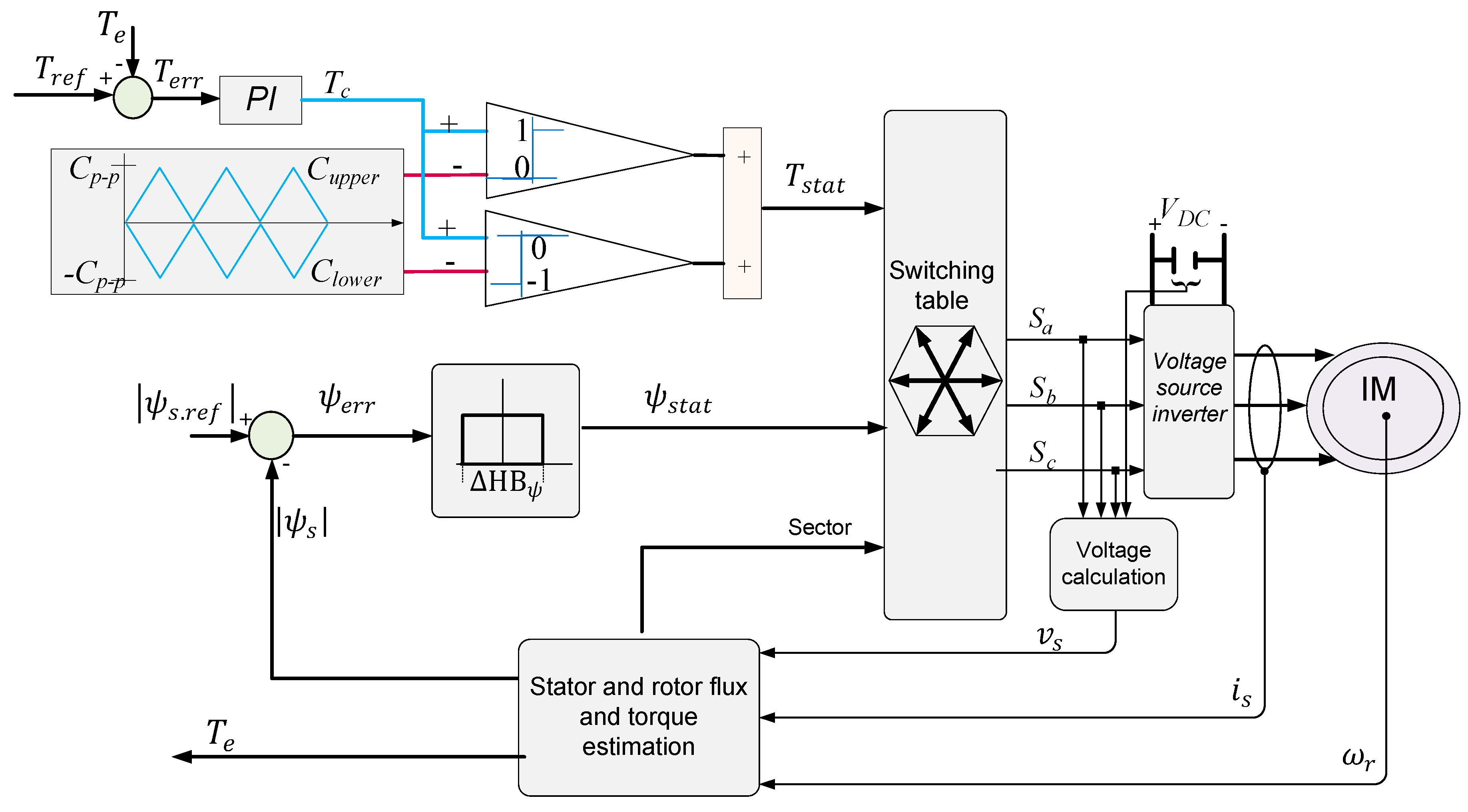
3. Proposed CFTR-DTC with Interleaving Carriers
One of the main issues normally linked with the DTC is the capability to have a well-flux regulation throughout the speed range, particularly at very low frequency. Although good performance is accomplished in the conventional CFTR-DTC [
22], it still suffers from flux droop at low-speed regions during sector transitions.
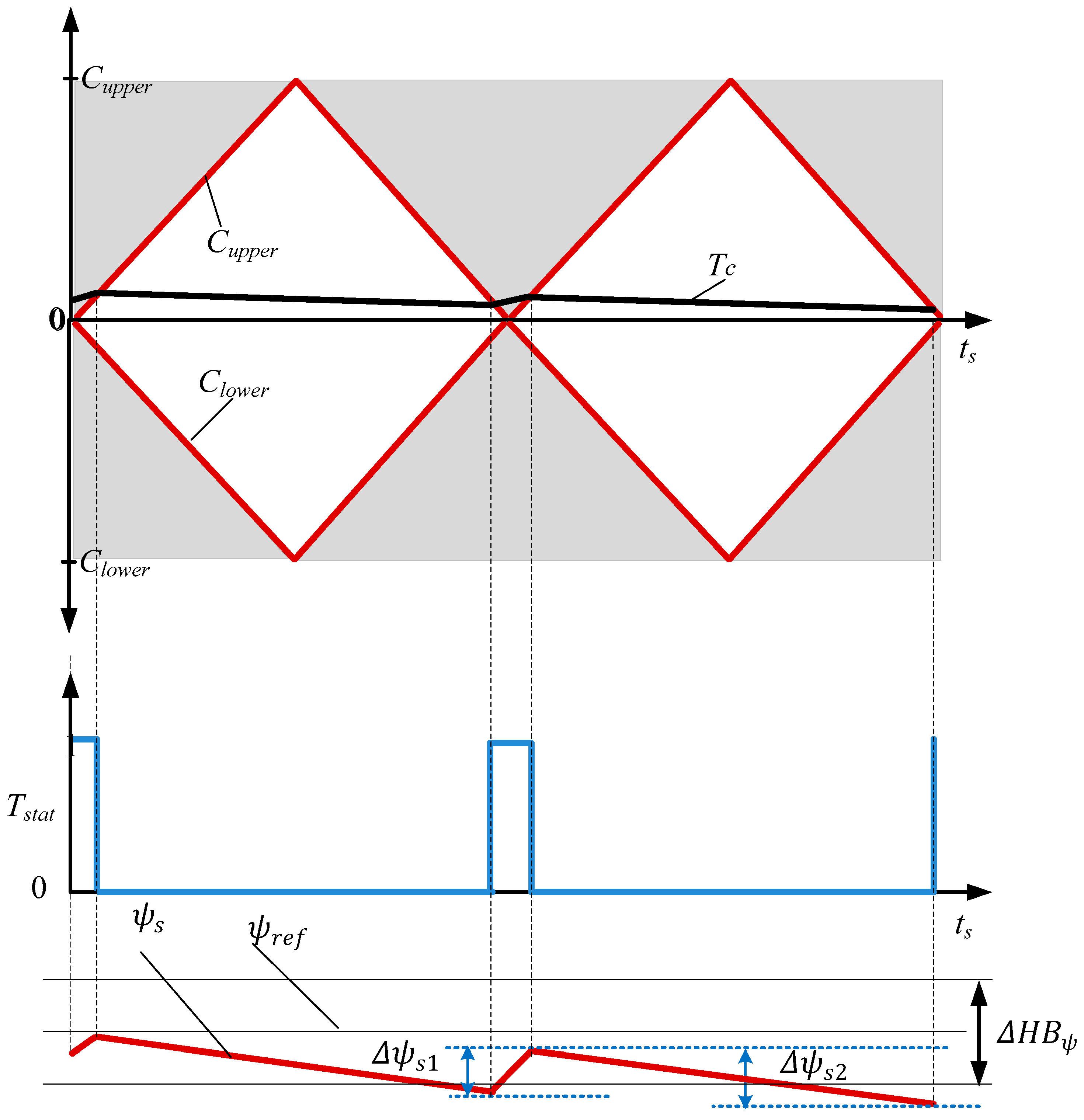
Figure 2 illustrates the flux regulation in the conventional CFTR-DTC where the flux cannot entirely fail because of regular switching of triangular carriers, which limit the torque slope variation and stimulate reverse-voltage vectors to reduce the torque rather than the zero-voltage vector [
22]. Nevertheless, it has flux-sector droop, particularly at the beginning of the sector [
25]. Consequently, this can cause non-sinusoidal current and degradation in the speed. There are two influences leading to this issue: The voltage drop across the stator resistance and the voltage vector accountable for incrementing the flux [
25].
To simply analyze this problem, Equation (1) can be arranged as follows:
If a discrete step,
Ts, is considered and the ohmic voltage drop is neglected, the change in the stator flux during the active voltage vector (
) can be given as
and the rate of change in stator flux during null-voltage vectors (
) can be expressed as
According to previous work [
22], the condition given by Equation (10) cannot be fulfilled at low speed because of the small magnitude of
.
When the rotor speed reduces to a certain low range, the null-voltage vector selection (whenever torque needs to be reduced) is dominant and critically reduces the magnitude of the stator flux, as shown in
Figure 2.
According to previous research [
22], the condition given by Equation (10) cannot be fulfilled at low speed because of the long magnitude of null-voltage vectors. Consequently,
becomes highly affected by the stator-resistance [
20], and, hence, the stator flux,
cannot follow its reference value, causing the condition in Equation (10) not to be fulfilled, as seen in
Figure 2.
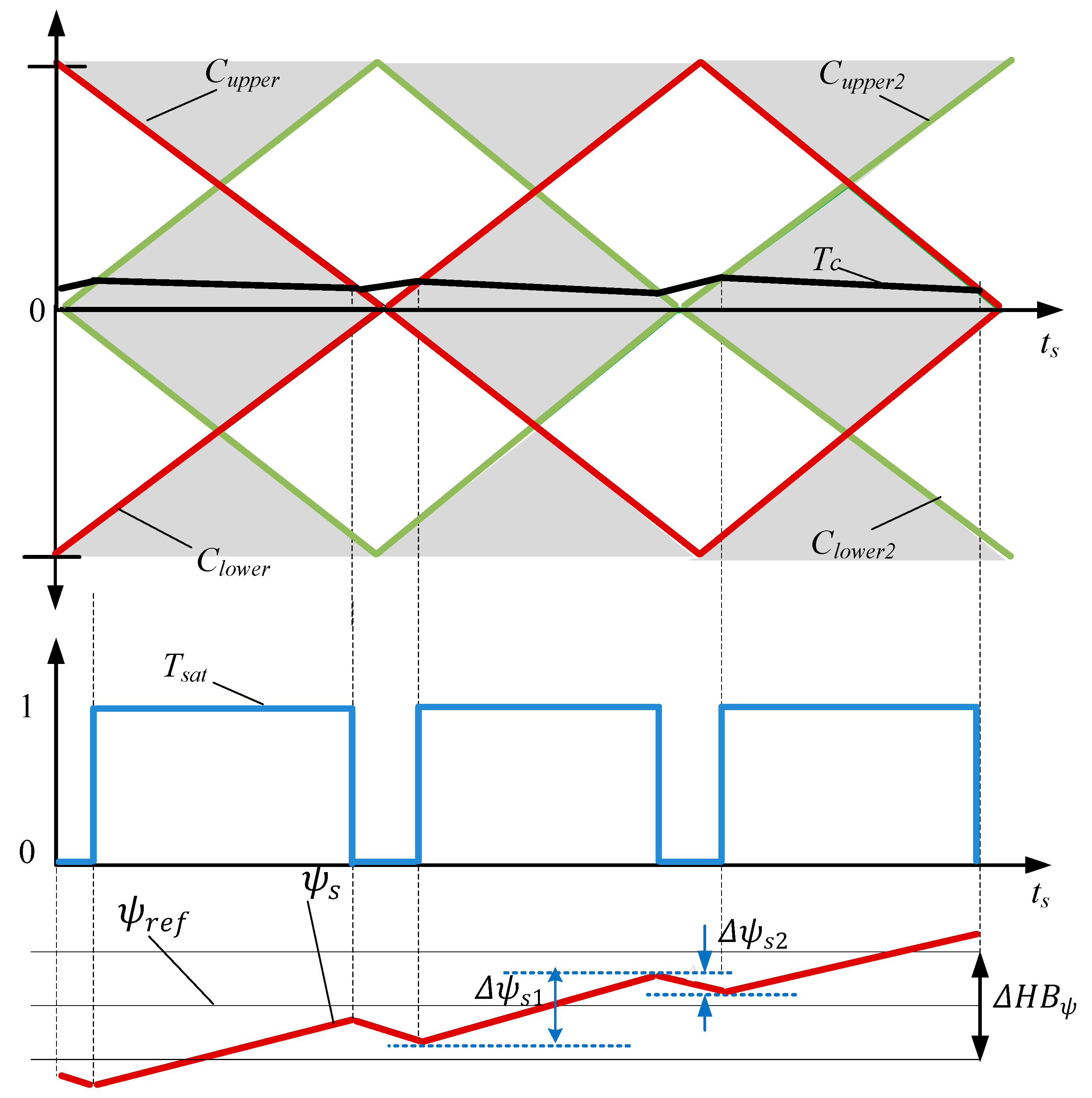
The main concept of the proposed controller is to have improved flux regulation at various speed ranges and to minimize the flux-sector droop at low-speed regions. For this reason, interleaving carriers are proposed to increase the duty cycle of the CFTR output,
Tstat, as shown in
Figure 3. It can be observed that
Cupper and
Clower are the original carriers, whereas
Cupper2 and
Clower2 are the added second upper and lower carriers, respectively.
The calculation for the torque error status in Equation (6) cannot be applied for the proposed torque controller. Hence, the proposed rules for the new CFTR output,
Tstat, are given in
Table 2. Unlike work presented elsewhere [
25], where only the low-speed range is considered, the proposed torque rules cover all speed regions. From
Figure 3, it is clearly observed that the time interval for a shadowed single triangle is half that of the original carrier, which leads to the increase of the switching frequency by two times. Additionally, the duty cycle becomes much larger than that in the conventional CFTR. Consequently, this can considerably reduce the effect of the ohmic drop and, hence, improves flux regulation at low-speed regions.
It can be seen that the output of the proposed interleaving-carrier-based CFTR is similar to that of the single-carrier controller [
20], which is either of three states: 1, 0, or –1. For better illustration, the active states of 1 and −1 are obtained when PI output lies in the gray area, whereas the zero state is achieved when the PI output signal is located in the white area.
It should be noted that for ensuring a proper torque operation of CFTR gains of the PI controller are essential. Hence by adjusting the PI parameters, optimal operation for the motor drive can be achieved.
The selection of PI parameters can be carried out using the same procedure in [
24], yet the whole peak of the carriers should be taken into account for the selection of PI gains. In principle, the output of the proposed interleaving-carrier-based CFTR is like that of a conventional controller [
20], which can be either one of three states: 1, 0, or –1.
4. Simulation Results
To confirm the validity of CFTR-DTC with a single carrier and CFTR-DTC with interleaving carriers, they were simulated using the PSIM simulation tool. The parameters of the induction motor are provided in
Table 3.
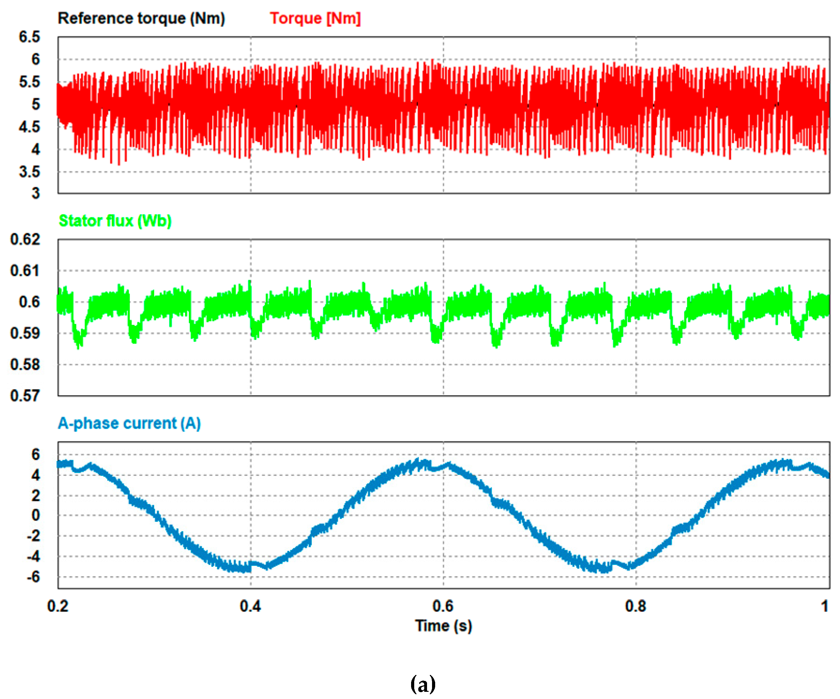
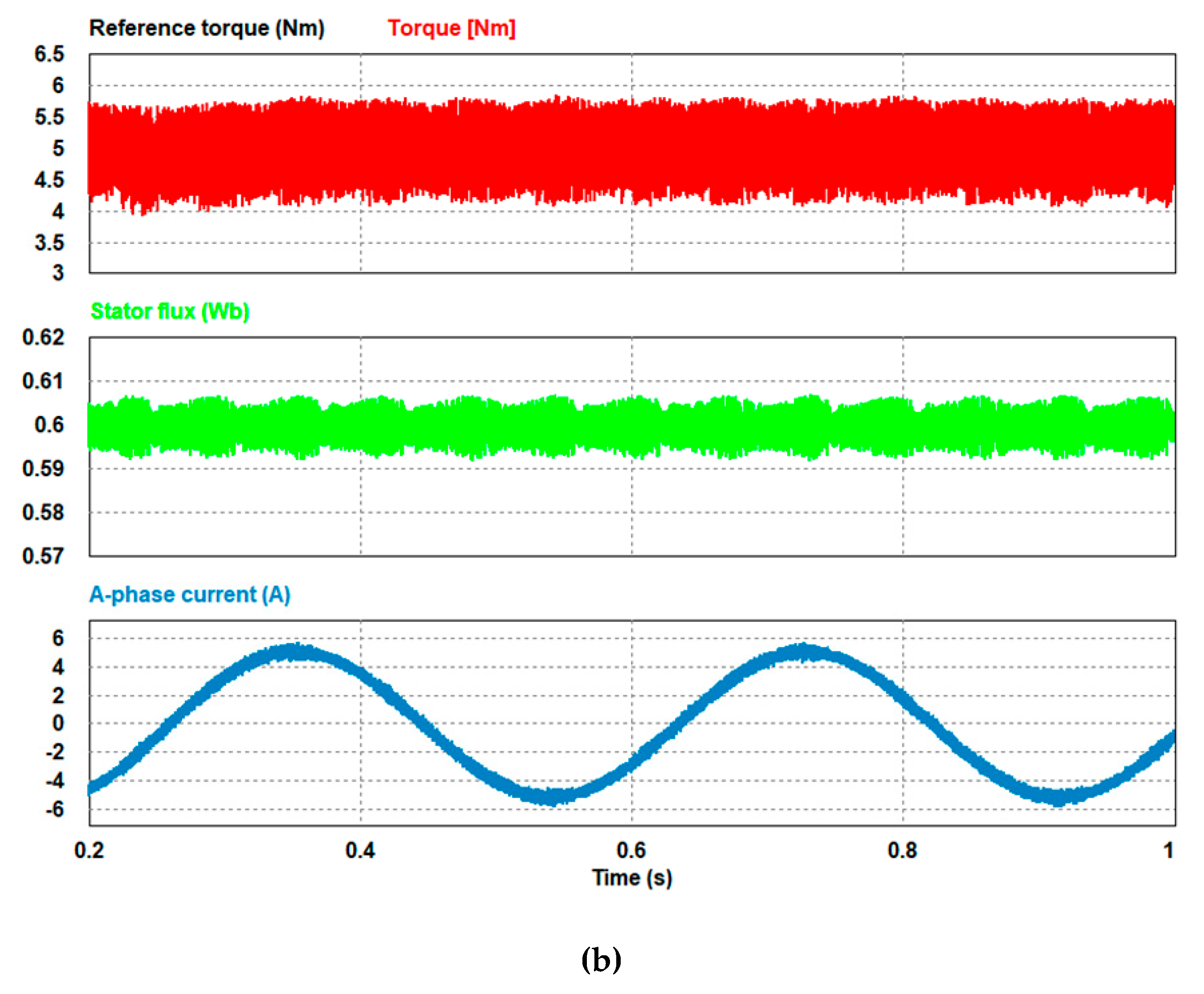
Figure 4 shows the steady-state performance of CFTR-DTC with a conventional carrier and CFTR-DTC with the proposed interleaving carriers at 100 rpm under a 5 Nm torque load. In the conventional algorithm, when applying a triangular carrier, it is apparent that the periodic flux-sector droop happens owing to the long duration of the zero-voltage vectors and also the weakened radial voltage components in the sector transitions. Consequently, this results in the distortions of current waveforms. In contrast, when the interleaving carriers are applied, the stator flux becomes well regulated and stable owing to the reduction of the ohmic voltage drop, because the zero-voltage vectors have a shorter duration. Consequently, this leads to excellent improvement of the current waveform.
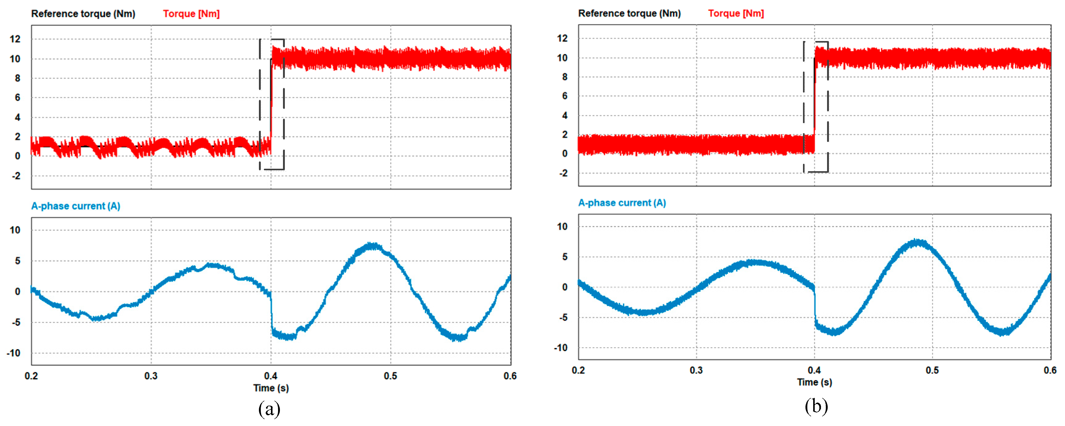
Figure 5 shows the dynamic responses for the conventional and proposed CFTR-DTC algorithms under a speed load of 100 rpm.
Figure 5a shows the step change of torque from 1 to 10 Nm, where a single carrier is applied. However, in
Figure 5b, the proposed interleaving carriers are implemented with a higher duty cycle; thus, the torque increases with the reduced interval of the zero-voltage vector. It can be seen that the current waveform for the conventional CFTR-DTC has higher distortions at light toque when compared to the higher torque after the application of a lager torque reference. Nevertheless, the proposed CFTR-DTC has excellent current waveform before and after the application of the larger torque reference.
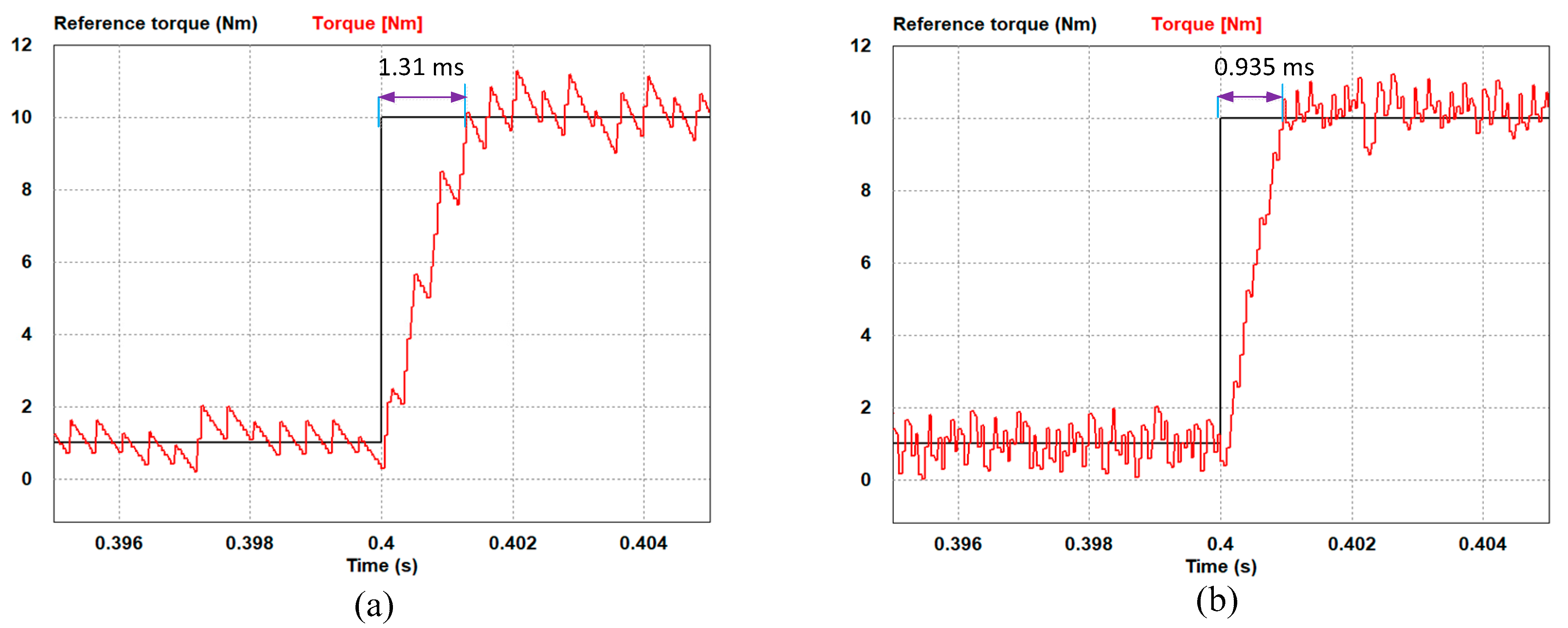
From the enlarged image in
Figure 6, it can be observed that when the reference torque steps up, the arrival time of torque of the proposed CFTR-DTC changes from 1.131 to 0.935 ms as shown in
Figure 6b. This indicates that the CFTR-DTC method with proposed interleaving carriers provides a faster torque response.
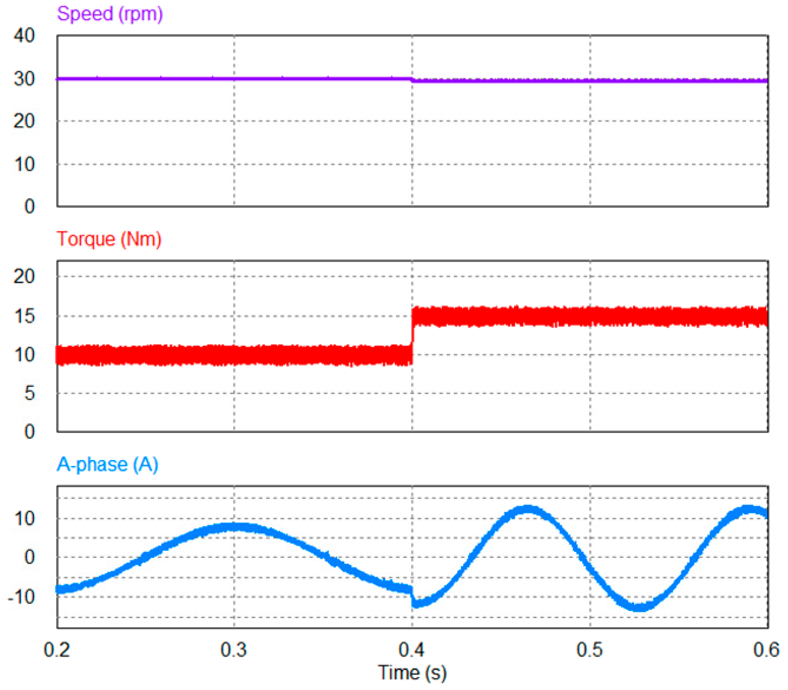
The proposed CFTR-DTC with interleaving carriers has been investigated for external load disturbance as shown in
Figure 7. The load torque is suddenly changed from 10 to 15 Nm. It can be observed that the speed waveform shows very good robustness against the load disturbance. The torque and current ripples are almost identical before and after the larger load disturbance.
5. Implementation and Experimental Results
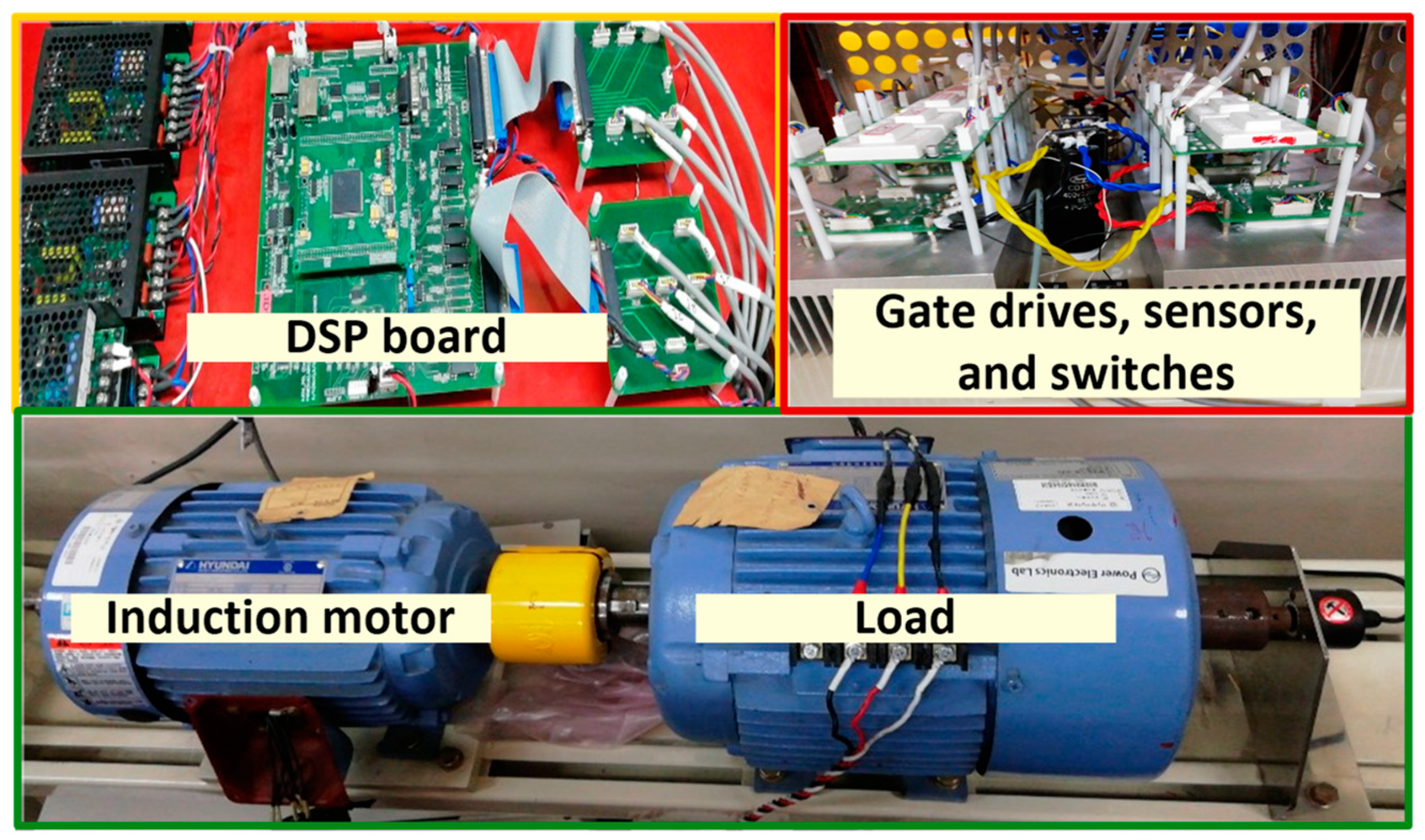
To investigate the interleaving carriers for the performance of CFTR-DTC of IM, the experimental setup provided in
Figure 8 was used. It contains a DSP model TMS320F28335 control board and a three-phase intelligent power module equipped with insulated gate bipolar transistors (IGBTs) from SEMIKRON. In addition, two LAH 50-P current transducers from LEM are used to sense the current. A 2000 PPR encoder was used to obtain the measured speed. To load the machine, a 5.5 kW IM controlled by a commercial YASUKAWA inverter was used. The sampling time of DTC and CFTR-DTC including the proposed methods was 40
. The parameters of the induction machine are tabulated in
Table 3. It is worth mentioning that the data acquisition system has a limited bandwidth. Hence, the quantization error increases particularly in the zoomed images.
In the practical implementation, the application of the interleaving carriers in CFTR-DTC can improve the flux-sector droop, but at the expense of higher-torque ripples when compared with the single-carrier method [
25]. Unlike in a previous study [
24], where the interleaving carriers were utilized partially for the low-speed region, here, the interleaving carriers are fully utilized. However, in this method, the switching frequency of the carrier can also be increased by designing the step change of carriers
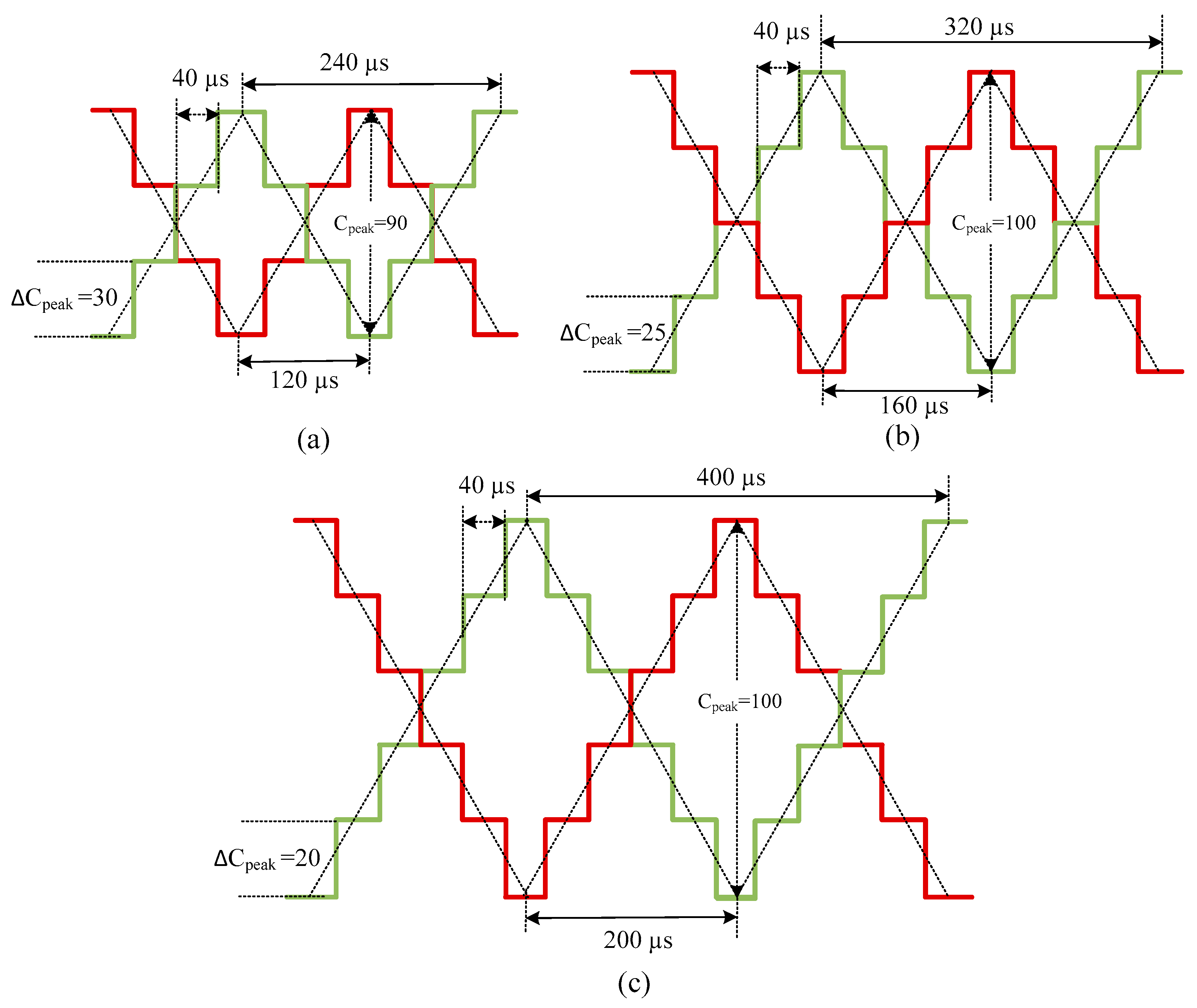
ΔCpeak for both carriers at the same sampling period for investigating the performance of CFTR-DTC with interleaving carriers. In this regard, three interleaving carriers are suggested, as follows.
Interleaving CFTR-3 (
Figure 9a) — Peak of the wave carrier (
Cpeak) is set to 90.
ΔCpeak increments 30 units per step size. Hence, the frequency for each carrier is 4166.66 Hz.
Interleaving CFTR-4 (
Figure 9b) —
Cpeak is set to 100.
ΔCpeak increments 25 units per step size. Hence, the frequency for each carrier is 3125.00 Hz.
Interleaving CFTR-5 (
Figure 9c) —
Cpeak is set to 100.
ΔCpeak increments 20 units per step size. Hence, the frequency for each carrier is 2500.00 Hz.
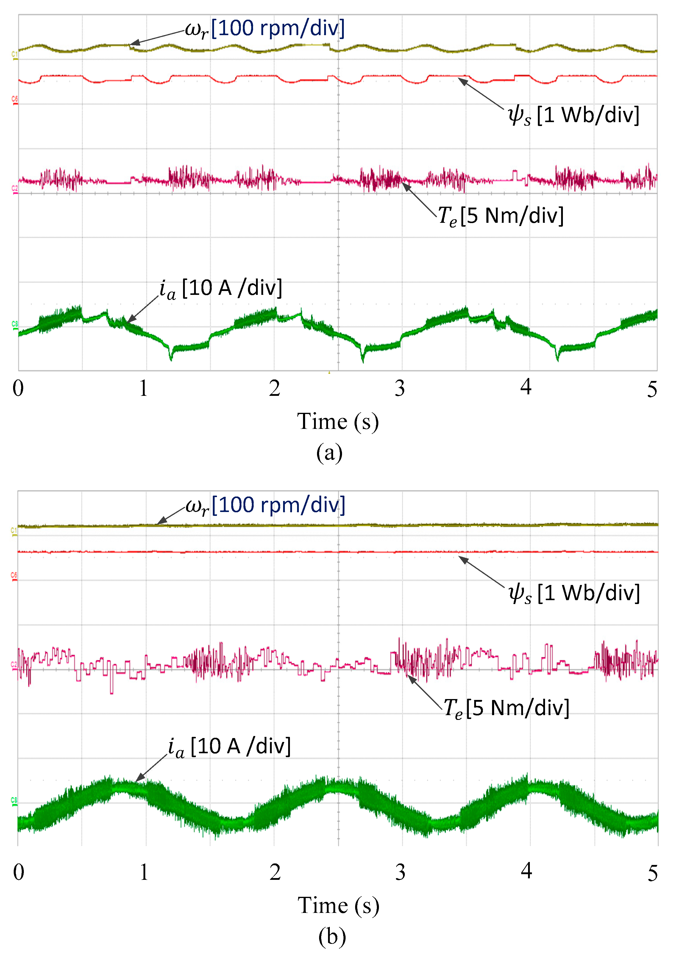
Figure 10 shows the steady-state waveforms of speed, flux, torque, and current at 20 rpm for the conventional CFTR-DTC and the proposed CFTR-DTC with the interleaving carriers, respectively. It is clearly shown that the stator flux in the CFTR-DTC with conventional single carriers suffers from periodic sector-flux droop during low-speed operation, as shown in
Figure 10a. As a result, the waveforms of speed and current become badly distorted, and the electrical torque is not stable. When interleaving carriers are applied, significant improvement is achieved in the stator-flux regulation and, hence, in the rotor speed and current waveforms, as shown in
Figure 10b. Nevertheless, it is apparent from the figure that the torque and current ripple increase.
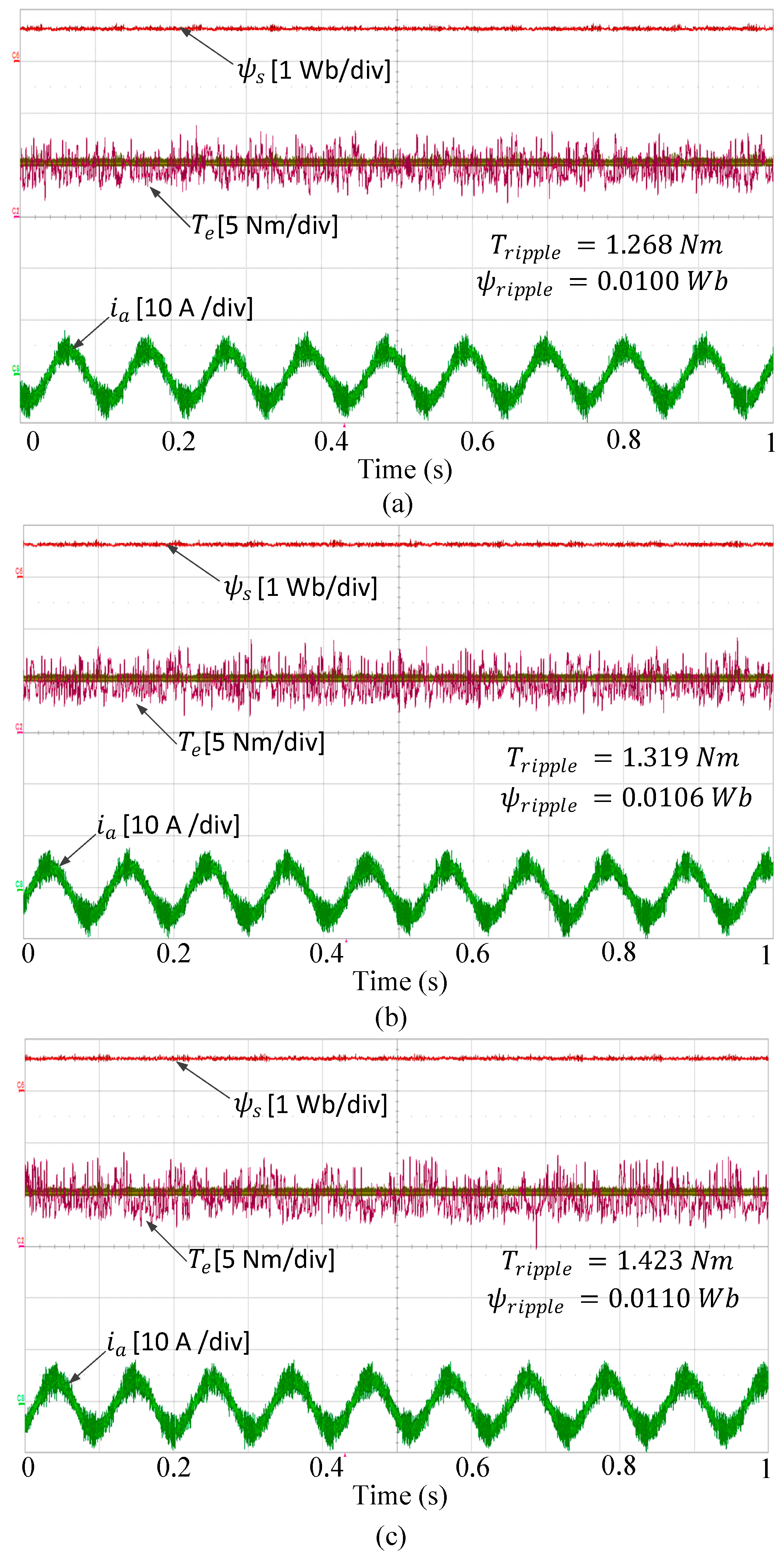
Next, the performances of CFTR-DTC with the three interleaving methods are evaluated and compared in terms of the motor torque and stator flux ripples.
Figure 11 shows the steady-state operation of interleaving CFTR-3, interleaving CFTR-4, and interleaving CFTR-5. To have a fair comparison among the three methods, the investigation was performed under the same speed and load torque conditions so that the rotor speed operated at 500 rpm with a load torque of 5.0 Nm. The calculations of torque ripple (
) and flux ripple (
) for all control methods were done online at steady-state operation using the following expressions [
26].
where
n is the number of sampling times, and
and
are the average values of the torque and flux, respectively.
The torque ripples were 1.268 Nm for interleaving CFTR-3, 1.319 Nm for interleaving CFTR-4, and 1.423 Nm for interleaving CFTR-5, respectively. The flux ripples of interleaving CFTR-3, interleaving CFTR-4, and interleaving CFTR-5 were found to be 0.0100, 0.0106, and 0.0110 Wb, respectively. It is clearly seen that interleaving CFTR-5 had the largest torque and flux ripples. However, interleaving CFTR-3 had the smallest torque ripples and flux ripples owing to the increase of the carrier frequency.
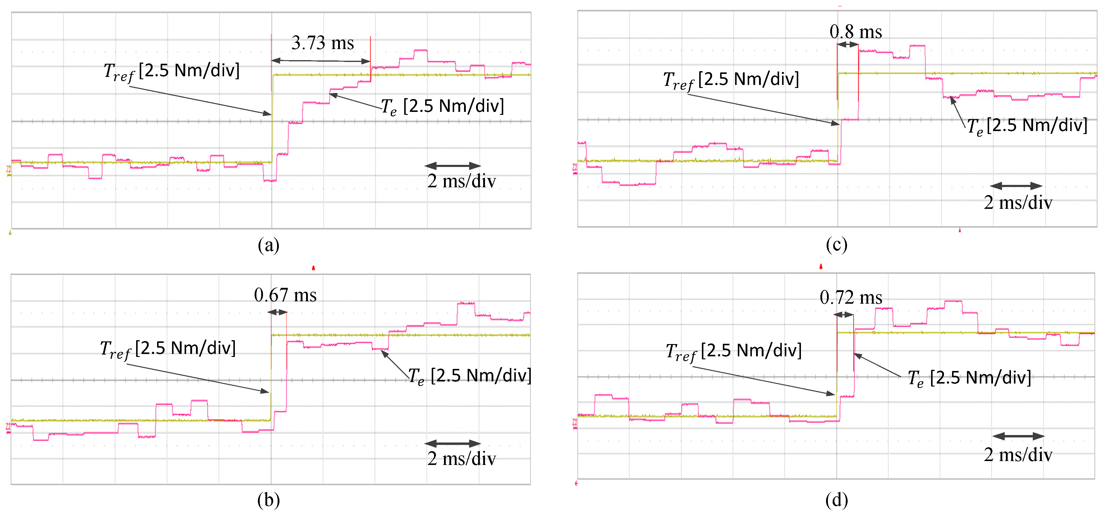
Figure 12 shows the dynamic torque performance for the conventional CFTR-DTC and interleaving CFTR-3, interleaving CFTR-4, and interleaving CFTR-5. A step change of torque from 1 to 9 Nm was applied during operation at 300 rpm. Although the conventional CFTR-DTC had the smallest torque ripples, it had the slowest torque dynamic response of 3.73 ms when compared with the proposed interleaving methods. All the CFTR-DTC methods with interleaving carriers had excellent torque performance. However, interleaving CFTR-3 had the fastest torque response of 0.67 ms.
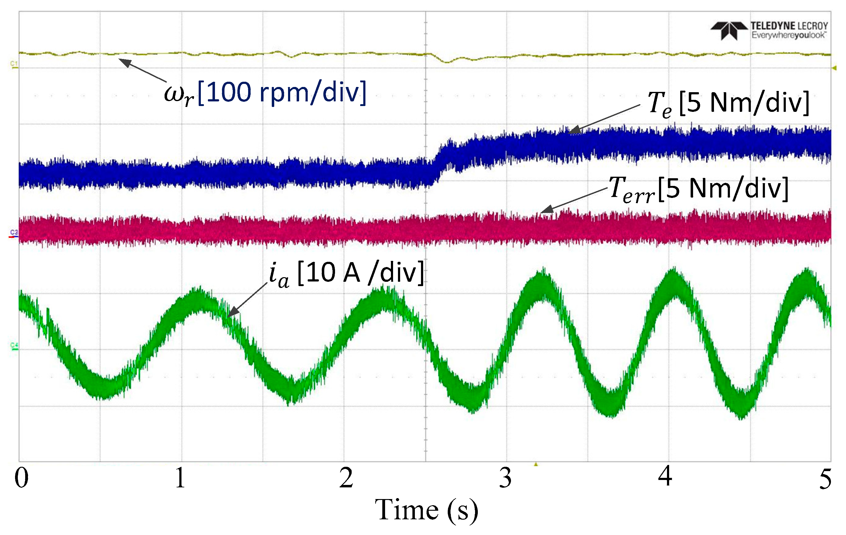
Finally, the proposed CFTR-DTC with interleaving carriers has been also tested in the real experiment for external load disturbance as shown in
Figure 13. As in the simulation, the load torque is suddenly changed from 10 to 16 Nm when the IM is running at very low speed (i.e., 30 rpm). It can be observed that the speed waveform shows very good robustness against the load disturbance since it has fast recovery after the load disturbance. The torque and current ripples are almost identical before and after the larger load disturbance. The torque error is also constant before and after the disturbance. It is worth mentioning that all discrete interleaving carriers can show the same response against load disturbance.


