1. Introduction
Connection to the distribution grid is one of the most important aspects of the future of renewable energy sources. Undoubtedly, this represents a source of opportunities and technological problems to be addressed and solved, but very often, we do not dwell on the fact that these sources can also be used as a tool to provide innovative network services [
1,
2,
3,
4]. In the so-called micro-grids, that can work either in island mode or connected to the main electric network, there are several issues that needs to be addressed. Considering that the latter is usually composed of synchronous generators (SGs), which have the capability to stabilize the electric network itself thanks to their mechanical inertia. Indeed, for instance, following a sudden variation of the injected/absorbed active power, due to the connection or disconnection of some electric loads and/or power sources, an electro-mechanical transient takes place. Therefore, the mechanical speed of SGs, which are connected to the electric network, starts to decrease or increase and, at the same time, the grid frequency decreases or increases as well. During the electro-mechanical transient, the variation of the kinetic energy stored in the rotating rotors of SGs helps stabilize the transient itself. This stabilizing effect depends on the total equivalent inertia of all the SGs owing to the electric network. Conversely, the increasing amount of renewable energy sources (RESs) installed in the micro-grids makes the total equivalent mechanical inertia of the electric network lower. In fact, the RESs, such as PV and wind systems, are connected to the point of common couplings (PCCs) through the power converters, which, for their nature, do not have any mechanical inertia. Therefore, stability issues can arise, and in addition to the electro-mechanical transients due to power variations, the immunity of the grid to faults and disturbances are wakened [
5,
6].
Therefore, as the grid integration of RESs shows an upward trend in capacity, RESs’ intermittent feature will pose greater threats and challenges to the frequency stability of the grid. In order to overcome these problems, it is possible to use other SGs not for power production but only for helping the stability of the electric network, increasing its total inertia, and for acting other services such as the voltage regulation. These kinds of services are called ancillary services. In order to strengthen the frequency robustness, several potential solutions providing ancillary services have been studied. The back-up the SGs method directly adds supplementary SGs, giving more mechanical inertia to reinforce the frequency stability [
7,
8]. Another method dispatches storage units to provide fast-response power reserves when the system is under seriously insufficient conditions [
9,
10,
11]. Another way to act these ancillary services is to use the same power converters of the RESs with opportune control strategies. The virtual synchronous generator (VSG) is one of the most commonly applied methods. It emulates the mechanical behavior of SGs by providing specific active power [
12,
13,
14]. The amount of virtual inertia applied to the grid is restricted by the active power rating of the power converter, DC source and DC-link capacitance [
15]. Moreover, it deals with only the active power, so accordingly, auxiliary devices that are already functioning in the grid are not able to share such a burden. Even though the VSG approach can be integrated in PV systems, the required power reserve for the virtual inertia drives down the original planned power yield, not mentioning the truth that it is only available when there is illumination [
16,
17]. Overall, the aforementioned methods manage the output power only to perform ancillary services instead of to increasing the capacity. Furthermore, they all depend on additional equipments, impacting the budget and the comprehensive control of the grid.
The assessments to be made in this context are many and varied. They range from planning to designing the system and control algorithm. Simulation and modelling therefore, become an important element in this scenario.
This is particularly true when you want to analyze their behavior at the system level, taking into account the interaction with other devices and especially the behavior of discrete and digital control logic. This can help real-time simulations (RTSs) in combination with hardware-in-the loop (HIL) techniques in order to validate the behavior of devices under study, combined with a more complex system [
18,
19,
20,
21,
22,
23,
24]. The approach is new and not well discussed in the literature. This paper is also a guideline to focus on some implemetation issues. There are several reasons to use these techniques, compared to traditional test-benches, for the testing and development of electronic systems. Soliciting the hardware through a more or less accurate physical model of the environment in which it will be used allows to obtain a greater understanding of its behavior in order to develop the control software or validate it.
Starting from this consideration, in this paper, an ancillary service to damp the frequency transient without adding any storage systems is analyzed in order to improve the understanding of the method. It is based on the existent equipment in the network, but does not sacrifice the nominal power output. It is a frequency-regulation ancillary service, responding automatically to detected frequency deviations at the point where SGs, RESs and loads are coupled. The proposed ancillary service aims to compensate for the brake force applied to the rotor of the SG under the loss of torque equilibrium. This ancillary service and the governor act simultaneously, but the former is much faster, acting directly on the armature currents. The proactive interfering currents come from the reactive power flow which is normally regulated to zero in many localized RESs, hence, neither additional reserves nor the under-use of RESs are required. The general idea is to make the RES absorb reactive power from the SG on experiencing a frequency drop, thus, the induced magnetic field inside the SG is weakened, thereby trimming the comprehensive electromagnetic force applied to the rotor. In other words, the frequency transients are partially transformed into that of the voltage on purpose. In order to endure the newly introduced reactive power flow, the power converter to implement the ancillary service has to be sized a bit more than the nominal rating. The original contribution of this work is to explain the theoretical aspect of the proposed method and to implement this model in a controller-hardware-in-the-loop (C-HIL) real-time simulation, proving the effectiveness of an ancillary service. The model of this network is implemented in a real-time simulator to emulate the behavior of the real world but also to emulate the behavior of control algorithms. An additional electronic control board (ECB) is connected to the system to implement the system control with the same rules used in the final coding. This apparently simple implementation hides a series of issues that are usually insufficiently considered in this type of simulation. The first is the choice of proper interfaces between different physical domains, since this choice results in a corresponding level of stability and accuracy. The second is the delay caused by the sampling action and the response time of the algorithm [
25,
26,
27].
In this article, we will start from the simulation of a microgrid and we will create a framework for the testing of control algorithms by means of Hardware in the Loop highlighting the implementation aspects and the main problems, generally not addressed in such a systematic way. The original aspect of the work is to provide a description of the ancillary service through methodological treatment of how to implement the simulation in a hardware simulator in the loop created in an innovative way to highlight both the simulation of the network, and the development part of control algorithms. In
Section 2, the model of the ancillary services will be presented while in
Section 3, the simulation framework will be described and deeply discussed. The implementation of digital PLL, which is one of the main issues, will be presented in
Section 4. The main result will be shown in
Section 5 and then the conclusion will be drawn in
Section 6.
2. Grid-Connected PV System: The Ancillary Service Description
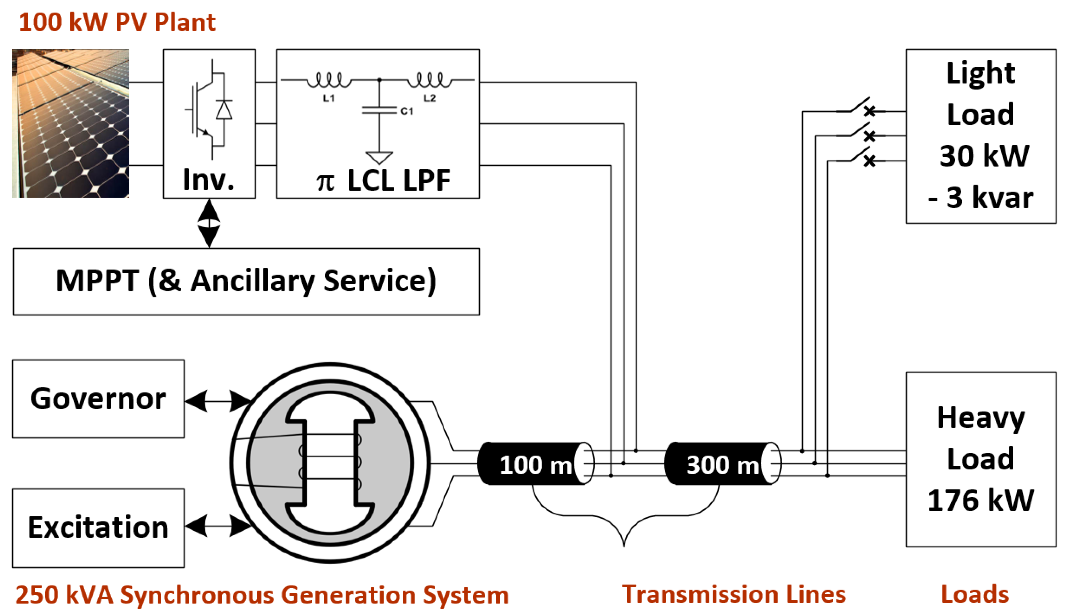
In order to explain the ancillary service proposed, we consider a simple microgrid made by a photo-voltaic (PV) plant, a synchronous generator (SG), short transmission lines and loads as an example as reported in
Figure 1. Unlike other solutions that require involvements of additional power supplies, we deploy the existent RESs which are integrated into the micro-grids to damp frequency transients. The target micro-grids are composed mainly of generation systems with natural inertia, e.g., SGs, RESs with power electronics interfaces, and loads. In view of the characteristics of such a hybrid network of slow and fast responses, we conduct a study on the coordination between fast and slow systems, as well as the advanced utilization of RESs’ power conversion system, exploring the added value of such networks without sacrificing the main mission. As to be elaborated in the following paragraphs, the strategy is to implement a reactive power flow control by fast power conversion systems during transients that are used to be handled only by the slow ones. Frequency variation on a grid occurs whenever the generators lose torque balance. If the mechanical torque is greater than the electromagnetic torque, the frequency goes up and vice versa. The electromagnetic force depends on the state of the whole system, which is random and instantaneous; the mechanical power is based on the prime mover, which is inherently slow in response. Therefore, in a system where SGs dominate the global frequency behavior, frequency transients are closely related to the dynamics of SGs. Whilst traditional ancillary service control active power to damp the variation of the induced electromagnetic torque applied to the rotor, the proposed method handles reactive power instead to achieve the same goal. Both methods aim to reduce one component of the armature current, which produces braking force to the rotor.
The electromagnetic equation Equation (
1) suggests the hypothesis that reactive power regulation can benefit the frequency stability as well.
In Equation (
1),
k is a constant depending on machine parameters,
is the armature voltage,
is the electromotive force (EMF) induced by the field current, and
is the angle between
and
. The VSG method slows down the variation procedure of
, thus the prime mover deals with the slowed down transients more easily; while the proposed method handles
instead to compensate the variation in
partially. In order to regulate
, the most commonly used method is to regulate the reactive power flow. For a single SG,
depends on the excitation system and the power flow. Since the proposed method intends to inject or adsorb reactive power, the excitation system, which has the opposite effect to that of the ancillary service, has to be slower in response.
In order to explain it more explicitly, we consider a simple grid with a PV plant, a single-salient-pole SG, short transmission lines and loads as an example, and we will look deep inside the SG to see how the regulated reactive power reduces the braking force. We assume that the PV system generates the maximum active power, and the resistive components in transmission lines and stator windings are neglected for simplification. We will focus only on the armature reaction, which has the largest impact in our concern.
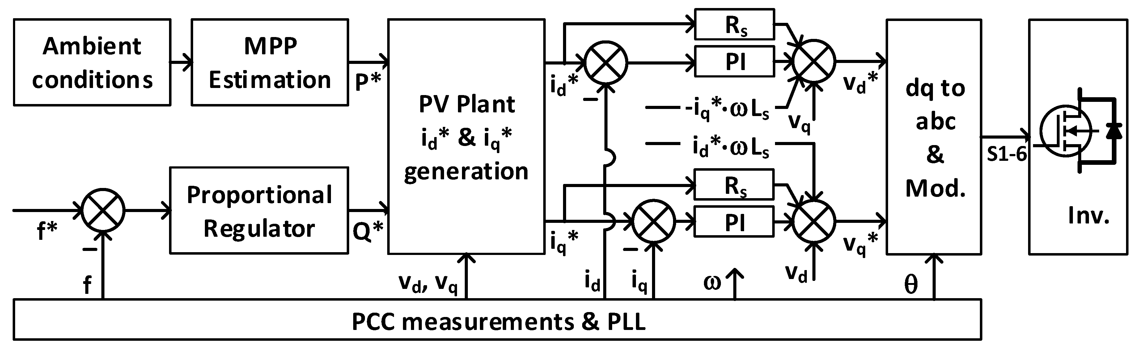
The observation point is the point of common coupling (PCC), and the d,q axis is built referring to this point. The control strategy implemented in the PV system, with the integration of the proposed ancillary service are shown in
Figure 2. The measurement and PLL block samples the PCC information and transforms it into d,q-axis components, so frequency, d,q voltage and current, and phase angle are all available for the the control loop. According to the measured ambient conditions, the maximum active power generation is firstly estimated. At the same time, a reactive power reference for the control loop is generated by the deviation of frequency apart from the reference. Therefore, the current references in d,q axis can be calculated knowing the estimates of power and the processing results of voltage, and the inner dual-current loop is formed, eventually providing driving modulation waves and driving signals to the power conversion block. The reactive power is controlled by measuring the PCC frequency: when there is frequency deviation from the reference, there is inner q-axis current flow; at steady state, q-axis current is controlled to be zero.
Figure 2 illustrates the implementation of the control strategy in PV system, with the integration of the proposed ancillary service. The measurement and PLL block samples the PCC information and transforms it into d,q-axis components, thus frequency, d,q voltage and current, and phase angle are all available for the the control loop. According to the measured ambient conditions, the maximum active power generation is firstly estimated. At the same time, a reactive power reference for the control loop is generated by the deviation of frequency apart from the reference. In order to achieve an interim reactive power control, the reactive power reference is linked to the frequency deviation by a proportional regulator, i.e., when there is frequency deviation, there is reactive power flow; at steady state, the reactive power is control to zero or near zero. Therefore the current references in d,q axis can be calculated knowing the estimates of power and processing results of voltage, and the inner dual-current loop is formed, eventually providing driving modulation waves and driving signals to the power conversion block.
The reactive power is controlled by measuring the the PCC frequency: when there is frequency deviation from the reference, there is inner q-axis current flow; at steady state, q-axis current is controlled to be zero. One intuitive method is to use a proportional regulator to generate the reactive reference, and q-axis current reference is thus calculated according to the status of the PCC.
3. The Model of the Grid and the Control Strategy
The aim of this section is to present the architecture for the control hardware-in the-loop (C-HIL), to validate the software control strategy directly implemented in the embedded ECB. The first step is the implementation of the model in a RTS, that in our case is the Typhoon Hil402 [
28] which deploys a Zynq-7 SoC processor with up to 4 cores (depending on the configuration) and is equipped with DI/Os and AI/Os. It is ideal for power system HIL test because of the integration of machine solver, ultra-fast real-time simulation time step 0.5–2
s and digital inputs oversampling up to 20 ns.
3.1. Implementation of the RT Simulation
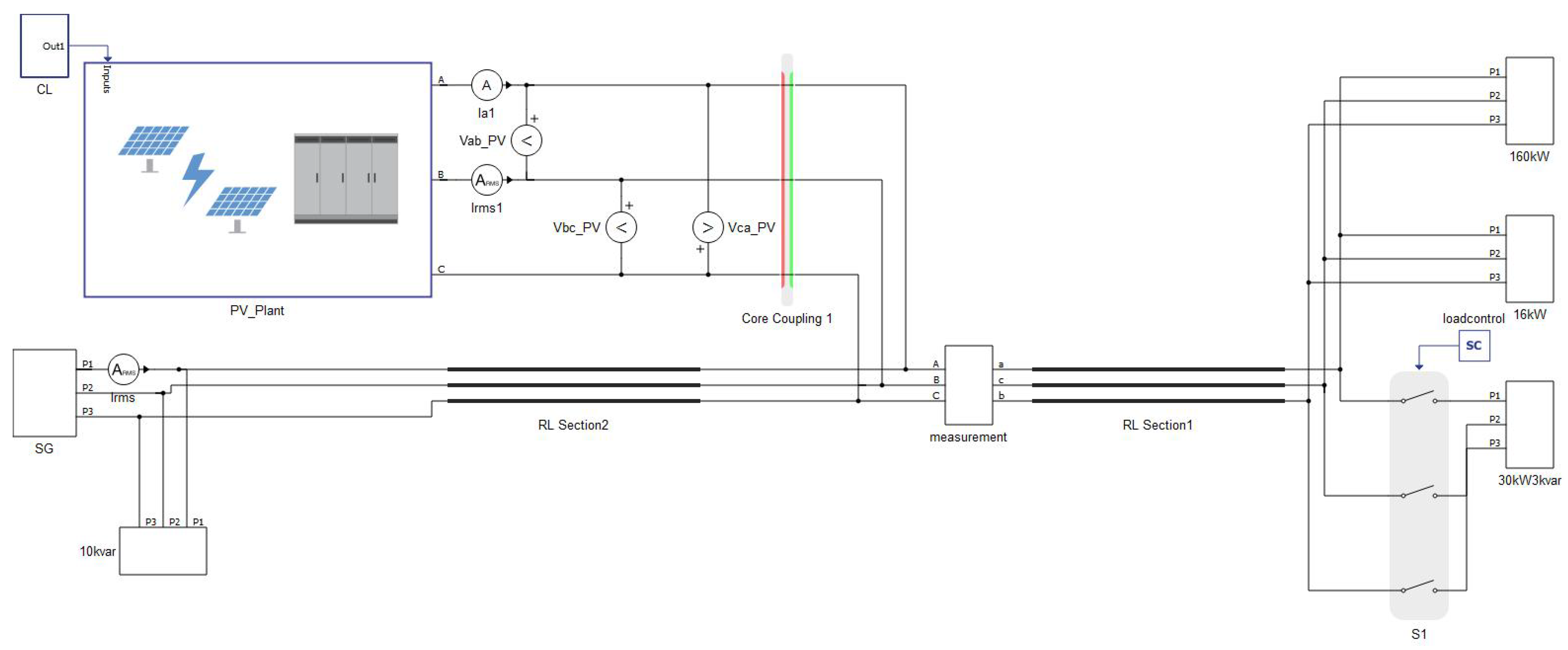
The system is designed with a SG, a PV system, loads, a circuit breaker and transmission lines as reported in
Figure 3 such as implemented in both real-time simulator Typhoon HIL402 [
28], and dSPACE DS1104, which are closer to the industrial implementation. The main parameters of the components are reported in the simulator reference manual [
28], and the chosen values are reported in the
Table 1,
Table 2 and
Table 3.
In order to reduce the total computation and to make a better use of the hardware resources, the system is subdivided into two sub-models partitioned into two different core of the simulator using an interface algorithm, that in this case is an ideal transformer model (ITM)-based core-decoupler, with the PV system executed in one core and the rest of the system in another [
23,
25,
26].
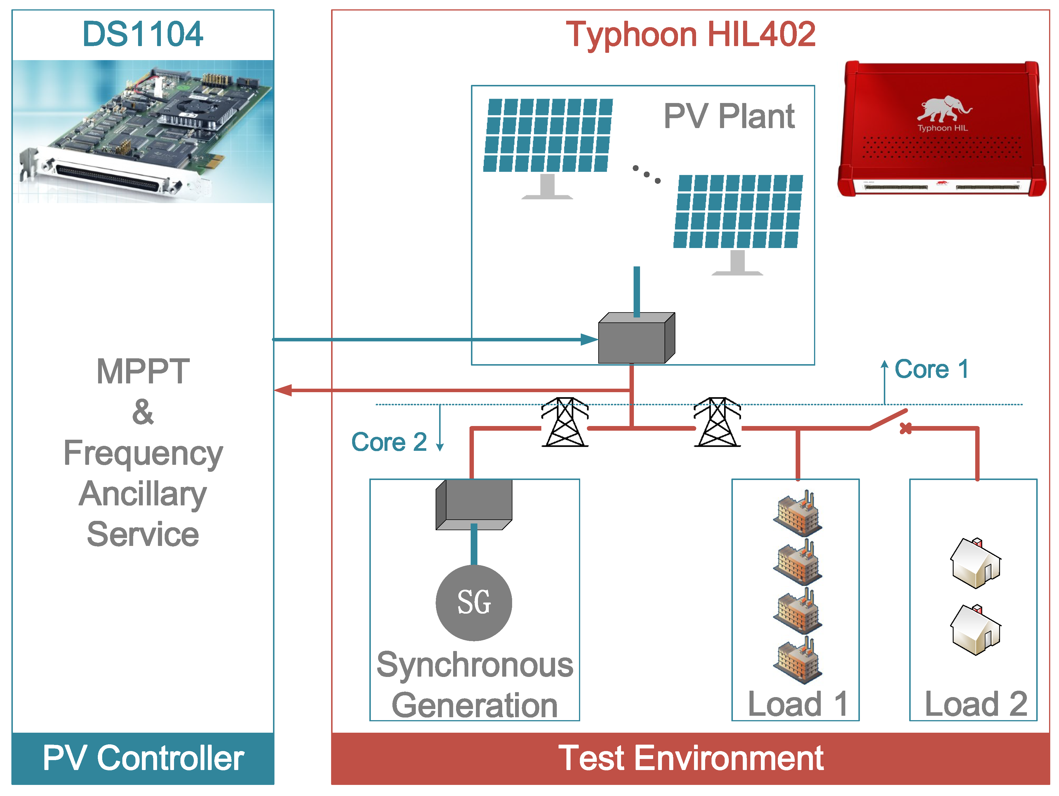
3.2. Implementation of the C-HIL
The C-HIL simulation is achieved by extracting the ancillary service algorithm from Typhoon HIL and subsequently embedding it into dSPACE DS1104 (dSPACE GmbH, Patborn, Germany) [
29]. So far, we have the Typhoon HIL emulating the physical part of the micro-grid and dSPACE emulating the digital controller, as illustrated in
Figure 4. DS1104 adopts an integrated host processor MPC8240 working at 250 MHz CPU clock. DS1104 is also equipped with four channels of 16-bit multiplexed A/D converter, four channels of a 12-bit parallel A/D converter, eight channels of 16-bit D/A converter and twenty parallel general purpose TTL I/Os.
We assume that the measurement and anti-aliasing filtering of PCC voltages, currents and frequency are done in the emulated physical domain. The controller samples the PCC information and generates PWM signals for the PV inverter. The Typhoon HIL ±10 V range 16-bit AOs have 0.01% gain error and 0.5 mV offset error. We scale down the voltages and currents by 100, i.e., 311 V/3.11 V and 300 A/3 V, If the sampling action is put at the beginning of the program, we would actually be trying our best to sample the state variables at the same relative time. Similarly, the PWM output action sometimes is put at the beginning to have the same effect, however, it will introduce one-step delay. Since the control loop is not fast, we decided to keep the PWM output action at the end to avoid the one-step del. The carrier frequency is defined as 19.96 kHz. In the preliminary stage, it was defined as 19.95 kHz for the purpose of eliminating even order harmonics. However, the 20 MHz clock rate of the slave DSP is not an integer time of 19.95 kHz, that is to say, we would obtain 19.94 kHz or 19.96 kHz instead of 19.95 kHz. The slight deviation will lead to a periodical time-variant phase shift between the carrier and the fundamental electrical signal. If the 20 kHz that appears in the uni-real-time simulation is used, there will not be a phase shift problem, but it has no advantage eliminating even order harmonics.
4. Digital PLL Discussions and Enlightenment of Embedded Control Design
Since the control algorithm is based on d–q coordinates, transforming angle is mandatory and important for the transformation. If the obtained by the embedded system deviates from that achieved under ideal and continuous conditions, variables seen from the control side will not be the same as those in physical world without drawing the operators’ attention. In real implementation, it is an unavoidable issue, but any clues locating the intrinsic reasons will help design and implement digital control more wisely.
The left flowchart in
Figure 5 is an example of how we have implemented the digital PLL at the control side. Every iteration with the phase angle achieved from the previous iteration is used to do the transformation and integration. We have simulated this solution and compared the result with an ideal one. At steady state, the digital phase angle solution is greater than the ideal one by 0.0314 rad under 10 kHz (Equation (
2)).
Furthermore, the interfacing from the actual electrical signals to the controller accessible digital signals imposes even greater impact on the phase angle deviation. The interface mainly consists of sensors, anti-aliasing filters and ADCs. Since sensors and ADCs have enough bandwidth for general electrical signals, only the internal data latency (typhoon-hil’s variables to AOs; dspace’s AIs to variables), synchronization condition and device conversion time are considered, i.e., absolute time delay. However, the anti-aliasing filters attenuate the signals depending on frequency, i.e., it will cause phase shift. We expect the PLL to obtain the phase angle of the fundamental frequency, thus the phase shift of the anti-aliasing filter at 50 Hz is recorded and the aforementioned absolute time delay is transformed to a phase shift based on 50 Hz.
After knowing all the above 3 aspects, we are able to roughly estimate the phase shift at 50 Hz and make the compensation like in the right picture of
Figure 5. As in our case, the anti-aliasing filter has cut-off frequency of 2 kHz, controller step is 100
s and the absolute time delay is estimated as 100
s.
The control algorithm is designed in this way:
are fed to the PLL to obtain
and
, then
is used to transform
to
. With the components
and
, we are able to calculate P and Q, thus P, Q are monitored at the control side and the derived current control loop can be formed. So the accuracy of the current feed-back depends on framework angle calibration. As mentioned before, the phase shift of the digital PLL comes from 2 parts: digital realization and interface. By compensating the PLL with the calculated value from Equation (
2), we can focus on the interface.
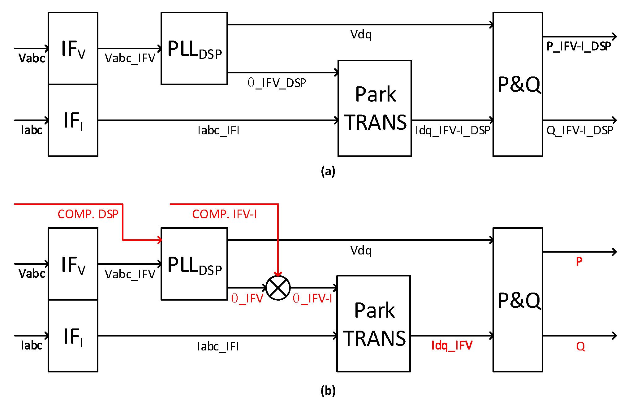
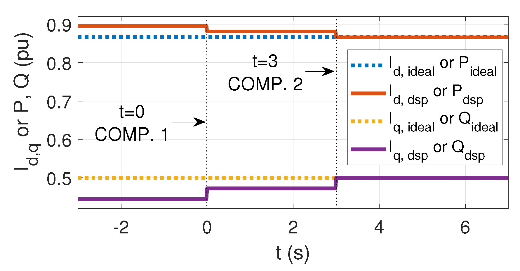
Figure 6 is the process to calculate P and Q in C-HIL or real implementation: the voltages and the currents seen at controller side are rotated by the voltage channel interface and by the current channel interface respectively. If these two interfaces have the same delay property, the relative phase difference between the voltages and the currents remain the same; that means that PQ calculation will not be influenced by the interfaces. However, in general case, current and voltage transducers can hardly have the same delay, i.e., there is a relative phase displacement caused by the non-uniformly of the two interfaces, which will lead to a lack of fidelity in PQ calculation. Based on these, firstly we add a phase compensation to the digital PLL to calibrate the PLL, then another phase compensation is added to compensate the relative rotational displacement of 50 Hz caused by the interfaces. It is tested under open-loop condition where
= 100
s, the original currents lead the original voltages by 30
and the current sampling channels are slower than the voltage sampling channels by 100
s. Before
, no compensation is added; at
s and
s, digital PLL compensation and interface compensation are activated successively. As we can see from
Figure 7, before compensation, the active power and d-axis-current are deviated from that in physical domain by 2.9%, and the reactive power and q-axis-current are by 5.6%; after compensation, they almost overlap with values in physical domain. The compensation design requires a thorough knowledge of the data latency inside the simulator or controller, hardware interface and PLL algorithm.
Even though we have calibrated the sampled currents to the framework of the sampled voltages, the modulation waveform based on the sampled voltage framework still has a phase shift from the supposed value in the physical domain caused by the voltage sampling interface. This phase shift will be compensated by of the current close loop, controlling the active and reactive power. In spite of the proposed calibration, the interface delay has to be considered when designing the control loop to guarantee the stability of the system.
5. Simulation Results
We have conducted the proposed method in the context of PV-SG-composed micro-grid on both real-time simulation and C-HIL simulation platforms. The simulation initiates from the state where the 176 kW load (50.3% of the nominal generation) has been connected to the PCC. The transients to be observed are induced by the connection and disconnection of another 30 kW &−3 kvar load at specific moments.
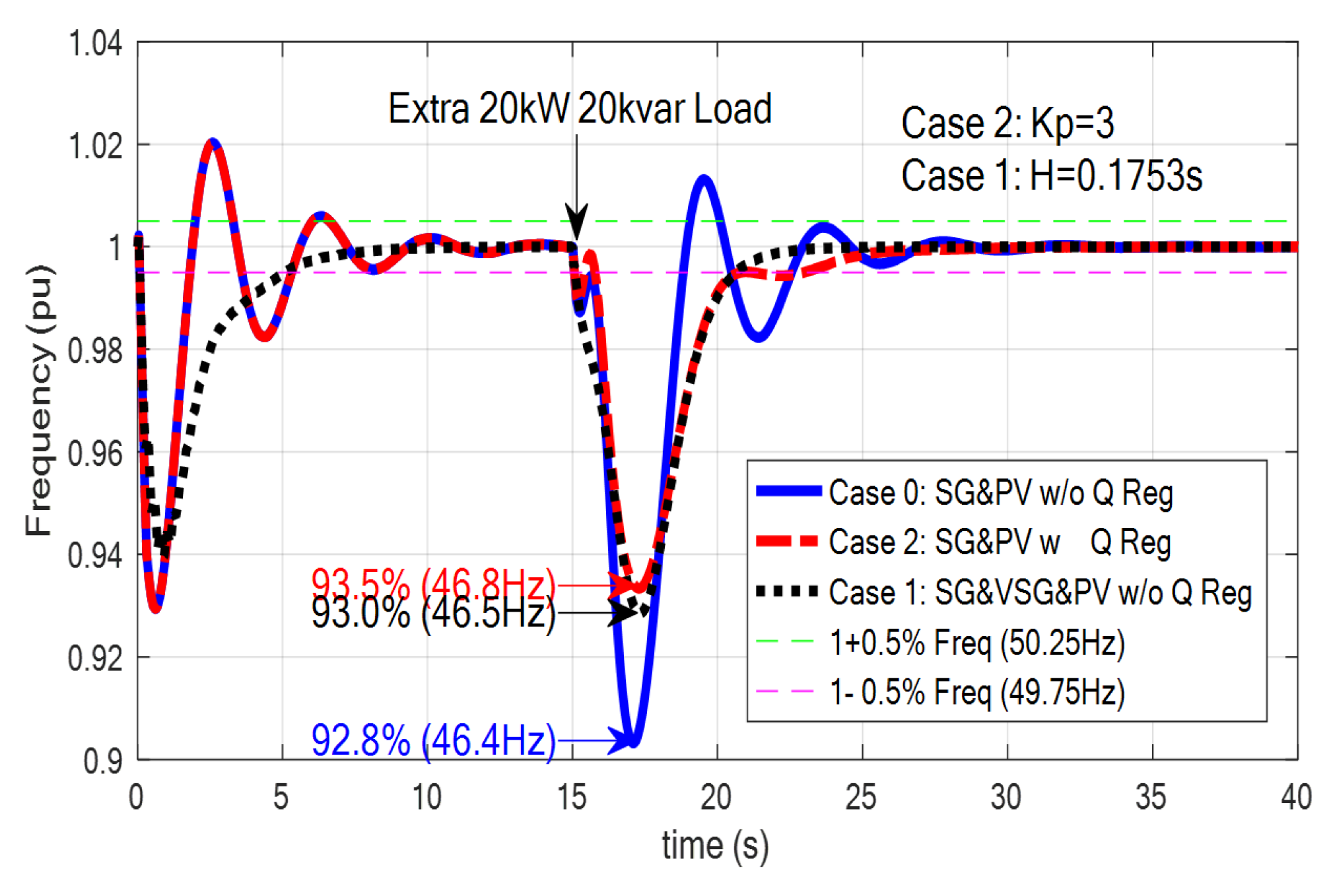
Figure 8 shows the simulation results of the frequency transients without ancillary service (blue), with the proposed method (red) and with the VSG method (black) respectively. This demonstrates that the proposed method is capable of attenuating the increase (decrease) in frequency caused by a connection or disconnection of the load by acting on the rate of frequency change (RoCoF). As expected in the theoretical section, the auxiliary service has a negative influence on transient voltage. The power flowing through the photovoltaic system reaches 22.5% of the photovoltaic system. total nominal generation to manage an active load change of approximately 8.6% of total nominal generation with settlement time of 6 s.
It is not so effective as the VSG method, but it can be used as a support to an operation using the already installed PV systems, without adding other converters such as in the case of VSG. However, when it comes to the practical implementation, the accumulation of all the non-ideal elements may bring unexpected results, for example, being ineffective or even instable.
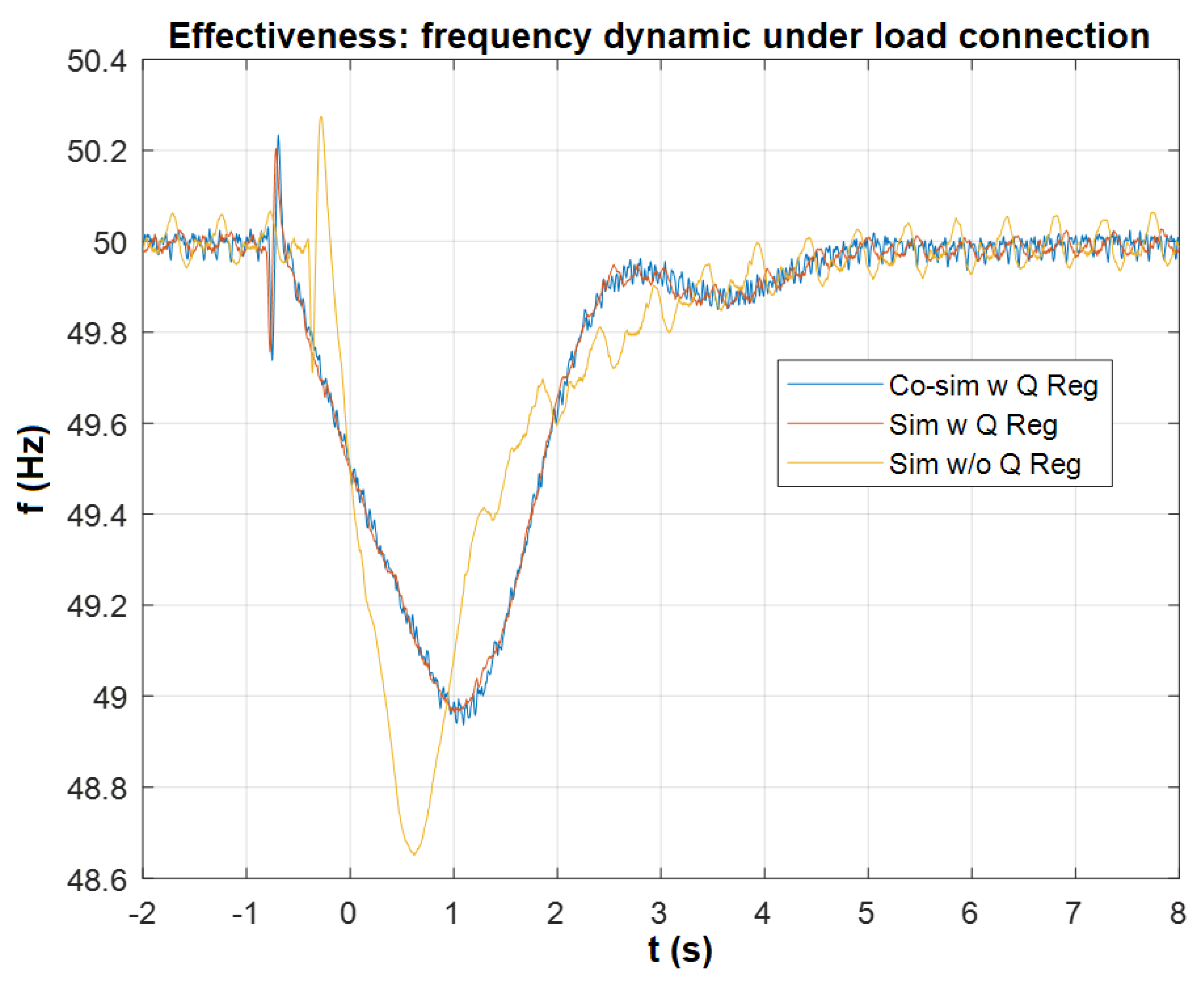
Figure 9 and
Figure 10 demonstrate the comparison between real-time and C-HIL simulations on the frequency transients. The low frequency components of the transients are visually the same, but the high frequency components are different, due to which the overshooting of C-HIL is slightly higher than that of real-time simulation. The origin of this difference is complicated. It is probably caused by the interface and the high-frequency-non-repeatability of the platform.
Table 4 and
Table 5 show how much the frequency overshooting has been attenuated by the proposed method both carried out in real-time simulation and C-HIL simulation. The results of real-time simulation have the smallest frequency overshooting during the load change. The frequency overshooting of C-HIL simulation is a bit worse than that of real-time simulation, but it is still superior to that of the case where no ancillary service is applied. In short, the practical implementation of the proposed ancillary service is promising, which has been proved by C-HIL simulation.
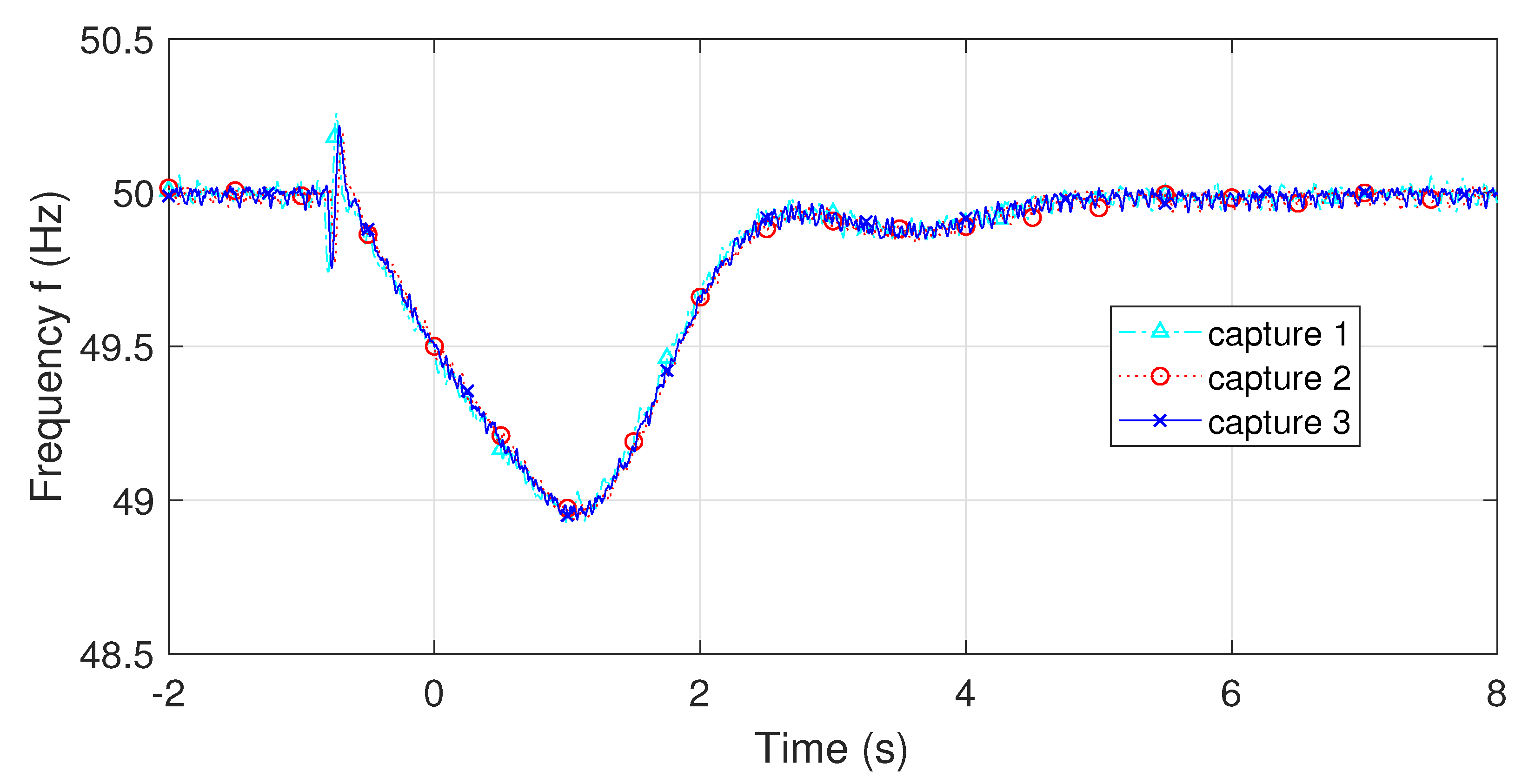
Repeatability is one important index of the simulation performance, so this experiment aimed to discover the repeatability of C-HIL simulation in this specific context. We have conducted the same experiment 5 times and their transients are shown in
Figure 11. The transients of the repeated experiments overlap well, even though differences are observed from high frequency components. Fortunately, in the study of micro-grid, whether it is the local device control, network control or fault detection, high frequency dynamics are not the main focus. However, it is good to keep in mind that, the slight difference between transients due to high frequency components, such as the magnitude of overshooting, may be caused by the coupling effect of the high frequency components. The causes are complex.
In C-HIL simulation, the interface between the controller and the emulated grid is constructed by AI/Os and DI/Os, among which AI/Os will bring about errors caused by the converters and the DI/O interface is sensitive to multi-rate and asynchronous operation, but these are not our concern in this article. the unintentional asynchronism probably originates from the execution mechanisms depending on the processor (controller: microprocessor; grid: FPGA), and the independent crystal inside each processor (this asynchronism is periodical).
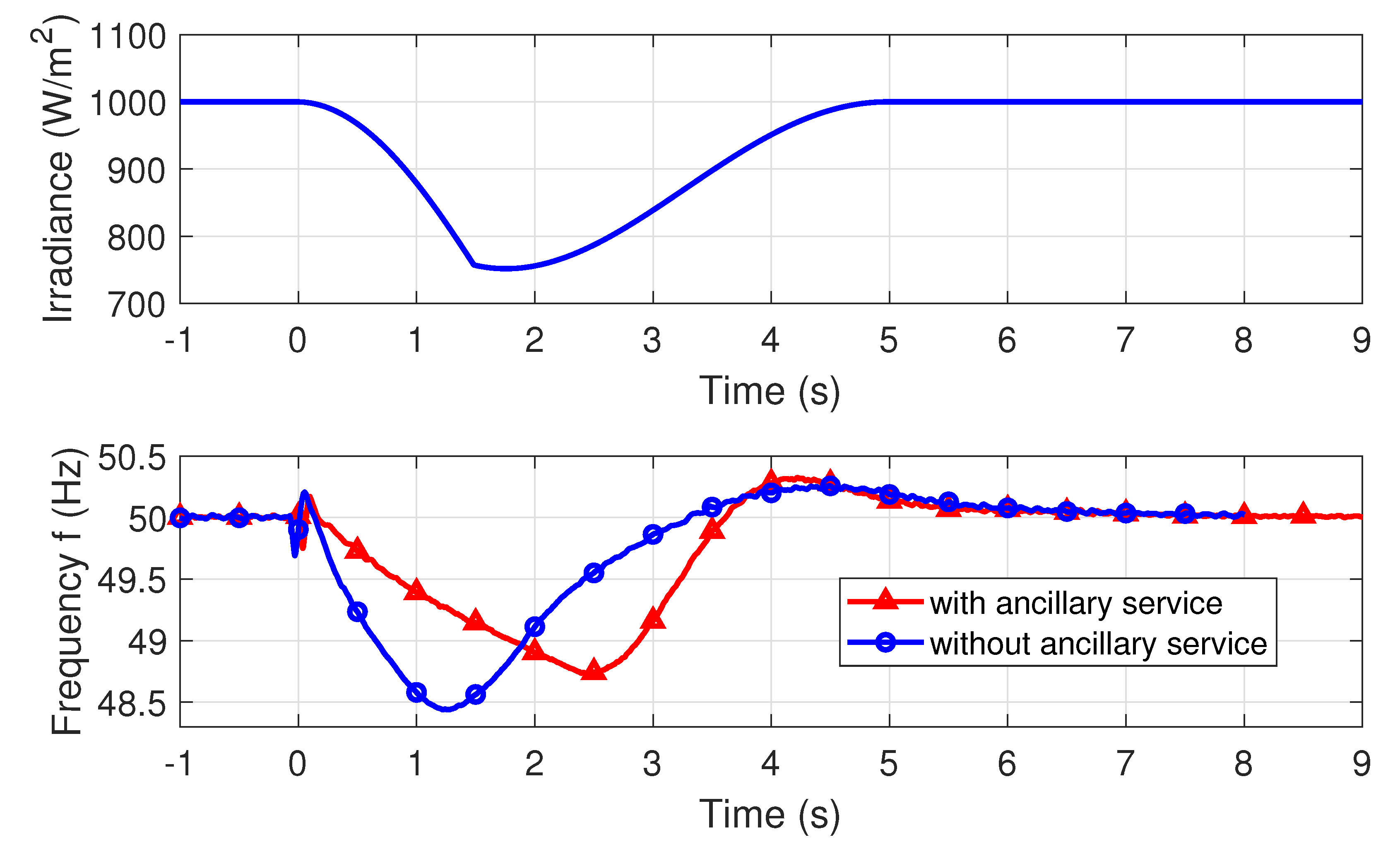
In order to study how the uncertainty of the PV plant impacts the ancillary service, we emulate a situation where the PV panels are temporarily shaded partially by a drifting cloud. So the irradiance in
Figure 12 has a continuous valley-shape variation, and it occurs at the same time as the load connection. From the test result, the ancillary service is able to damp the transient frequency overshooting in this case.
In simulations, it is possible to see that as the active power frequency transient is moved to the reactive power voltage transient helping the mechanical transient of real synchronous machines connected to the electrical grid by regulating their voltages through the injection/absorption of reactive power by converters of any RESs instead to support directly the grid frequency through the exchange of active power. The system was demonstrated through real-time and C-HIL simulations. The latter helped assess problems that can be found when implementing the control algorithm on an external microprocessor.
6. Conclusions
This article presented an ancillary service that can softly control the frequency of a microgrid using the reactive power available in a PV system and normally adjusted to be zero. The article presented the main feature of the algorithm, but at the same time, focused on the methodology of implementation of the HIL simulation with attention to the control and problems that these may have in the effectiveness of the system. The service was demonstrated, in fact, using a C-HIL framework where both the network model and the control algorithm were implemented. The first, in a dedicated real-time simulator, and the second, in an embedded system of the same performance as a typical control board.


