Article

Customized Vibration Generator for State of Health Monitoring of Prosthetic Implants and Pseudo-Bionic Machine–Human Feedbacks

1
Institute of Industrial Electronics and Electrical Engineering, Riga Technical University, LV1048 Riga, Latvia
2
“Tehniska Ortopedija” SIA, LV1012 Riga, Latvia
*
Authors to whom correspondence should be addressed.
Electronics 2019, 8(7), 810; https://doi.org/10.3390/electronics8070810
Submission received: 19 March 2019 / Revised: 9 July 2019 / Accepted: 10 July 2019 / Published: 19 July 2019
(This article belongs to the Special Issue Recent Advances in Biometrics and its Applications)

Abstract

:
Modern industrial, household and other equipment include sophisticated power mechanisms and complicated control solutions that require tighter human–machine–human interactions to form the structures known as cyber–physical–human systems. Their significant parts are human–machine command links and machine–human feedbacks. Such systems are found in medicine, e.g., in orthopedics, where they are important for the operation and functional abilities of orthopedic devices—wheelchair, prosthesis, rehabilitation units, etc. The mentioned feedbacks may be implemented based on the haptic perceptions that requires vibration actuators. In orthopedics, such actuators can be used also for diagnostic purposes. This research brings forward the idea of the use of 3D printing in conjunction with high quality permanent magnets. This allows for the achievement of better efficiency, smaller size, and the developing of actuators individually for particular circumstances. The obtained simulation, experimental data, and data about 3D manufacturing generally confirm the above hypothesis. In particular, the stiffness coefficient of the actuator’s membrane and attached mass, which can be changed easily during 3D printing, affects the frequency of maximal power output. Secondly, the 3D manufacturing process is quick, tunable and rather cheap. Finally, an elaboration of the design of the actuator that allows for the real-time modification of stiffness and mass in a program way is planned for future works.

1. Introduction

Nowadays, the interactions of more and more sophisticated power mechanisms, rapidly developing control solutions, and human beings through advanced communications has become incredibly tight, forming structures known as cyber–physical–human systems [1], which are kinds of cyber–physical systems—the systems which link physical and computer world [2]. Quite a lot of such examples can be mentioned. For example, [3] describes an dangerous for a work environment where a telepresence system is used to control a robot submarine in order to study the shelf of the Arctic Ocean. In turn, [4] presents an application with a harmful environment which describes the experience of using various telepresence systems in the nuclear industry. One more example of such systems [5] is operations in conditions of obstructed visibility, e.g., telepresence systems for underwater vehicle control. In this example, the data, acquired from the system, assisted the forming of augmented reality in order to avoid objects collisions. Alternatively, telepresence allows for the magnification of motion or torque amplitude, like it is done in [6] for the purpose of assembling of complex heavy mechanisms. Finally, an example, opposite to the previous ones, has to be mentioned [7]: In this example, telepresence allows for the making of very accurate micro-movements— manipulative methods that reduce such side effects such as hand tremors and erroneous sudden movements—for microsurgery.

1.1. Typical Use of Vibrations in Orthopedic Human–Machine–Human Interaction

A human–machine–human interaction, in particular, is important in orthopedics. It is of vital importance for the operation and functional abilities of various orthopedic devices—wheelchair, prosthesis, rehabilitation units, etc. This interaction has a number of information links between its components. Figure 1a presents an example of such an interaction in a mechanized prosthesis for a foot. In this figure, internal machine elements, including power actuators (in this figure, it is a controllable damper of artificial joint emphasized with green color), parameters, safety sensors (in Figure 1a,b, sensors of mechanical stress are colored with red), and control systems are linked with green and red arrows. In turn, the human–machine–human interaction is shown with blue and yellow arrows. This figure shows that, in general, the complete version of a human–machine–human interaction is bidirectional. Each system that includes a human being and a machine part, besides the purely internal machine regulation loops with references and parameter feedbacks, includes two information flows. The first evident flow conducts information from the human-operator to the machine part and provides a reference or command for the machine operation (blue arrow). In turn, the second information flow lets the human-operator know what happens with the machine part (yellow arrow). Historically, human-to-machine interactions are direct, active ones. They are based on simple motions (muscle force) to activate control elements—typically simple mechanical elements (joysticks, keyboards, pushbuttons, switches, etc.). In Figure 1a, a human–machine link is implemented using control panel with pushbuttons. In turn, machine–human links may also be direct and utilize vision or hearing senses.
However, this is not always convenient. For example, during surgery treatments, the surgeon must focus his attention on the treatment itself rather than on the supporting equipment. For this reason, newer systems use alternative interaction means. They read reference signals to control the machine from neural system or muscles, for example, applying myoelectric means. In turn, the feedbacks involves the formation of less informative human perceptions senses, such as haptic feedbacks. Paper [8] presented the use of a pseudo-bionic interaction in medicine, where an improved endoscope was used for micro-invasive surgeries on a human heart. The endoscope was equipped with a haptic force feedback system and a cartesian manipulator. It can be assumed that the machine–human link in Figure 1a utilizes the haptic perceptions of the limb and a generator of haptic stimulus (yellow) such as vibration.
The considerations mentioned above suggest the conclusion that, nowadays, a pseudo-bionic human–machine–human interaction is most realistically usable in various areas. In turn, pseudo-bionic feedback is a significant part of this interaction and may be implemented based on the haptic perceptions sense.

1.2. Typical Use of Vibrations in Techncial Diagnistics

Vibrations are also widely used in the field of electrical and mechanical engineering to detect and identify various hardware problems. Since vibrations are the result of macro and micro movements, their measurements provides a quite informative “fingerprint” of an object or process.
When vibrations are measured in different points of an object, they characterize the object itself [9]. Firstly, regarding rotation machines: Independently of the physical nature of these machines, they have bearings that undergo mechanical stress. Any defects in the bearings lead to the specific vibration pattern of the machine [10,11]. In addition, any fault in the power scheme leads to the change of the vibration pattern. For example, an analysis of the vibrations of an induction machine allows for the detection of broken rotor bars [12,13], as well as rotor and stator wire insulation defects [14]. The power scheme may be non-electrical. For instance, [15,16] discuss the opportunities of vibration diagnostics of blades in steam and gas turbines.
The above considerations must be given to things other than rotational machines. Other kinds of movement may be analyzed too. For example, analyze the audibly detectable vibrations of an on-load tap changer which followed linear movements [17]. Analyze the vibrations of a power transformer which did not include explicit moving parts but produced vibrations directly due to a strong electromagnetic field [18].
When distributing through a medium, a vibration changes its characteristics. Therefore, the measurements and comparison of vibrations in different points help to find and identify the parameters of a medium, the vibration impacts on the structure of an airplane [19], wing, a method to get the velocity and location information of rail vehicles based on the analysis of onboard vibrations [20].
The vibration actuators considered in this paper are primarily intended for the diagnosis of the technical health of prosthetic implants—metal rods fixed in a bone for the further fastening of prosthesis. They can be simultaneously applied to implement the human–machine–human interaction of a prosthesis.

1.3. Cells and Kinds of Haptic Perception

The cells of human body, responsible for haptic perception, are briefly described in Table 1. Each kind of these cells is characterized by adaptation speed (slow or rapid), as well as by an area in cells that is capable of receiving information. This sensitive area that is associated with particular sensitive cells is known as the mechanoreceptor. It can be seen that smaller mechanoreceptors provide perceptions that are more exact. In turn, a faster adaptation speed provides a better sensitivity. As a result [21], the Meissner and Pacinian corpuscles can be regarded as cells sensitive to vibrations, while the Merkel disk and Ruffini endings allow for the perception of static or rather slow phenomena: Pressure, texture (shape), temperature, etc.
It is possible to say that human beings are most sensitive to the vibration kind of haptic perception, because vibration-sensitive cells are located in different parts of human body. The most sensitive is, of course, skin. However, the cells that can sense vibrations are also located around bones, which makes it possible to use vibrations in prosthesis. In the most occasions, it is possible to train each particular person to perceive, recognize and interpret information coming through vibrations. However, the successful implementation of this approach requires the individualization of the corresponding vibration actuators to the sensitivity range of particular persons.

1.4. Prospective Use of Vibrations in Orthopedic Human–Machine–Human Interaction and Techncial Diagnistics of Prosthetic Implants

Vibration signals are used to inform patients about situations when it is necessary to do corrective activities with rehabilitation devices or patient’s body; posture change, the danger of losing balance, and the approach of a dangerous obstacle are all examples of such activities.
Devices, which provide a human body with adequate vibration signals through direct skin contact are known as vibration actuators. These devices are inbuilt in rehabilitation devices in construction points where they have direct contact with skin. This feature does not depend on the type of the device. The contact also could be provided by inbuilt actuators in cuffs, belts, etc. Direct contact with a patient’s skin allow for the use of one kind of actuator. However, skin contact requires a definite pressure. Therefore, constructive solutions are necessary to make sure pressure is provided.

1.5. Advantages and Disadvantages of Direct Contact (Exposure) Inbuilt Haptic Vibration Actuators

A direct contact actuator is a vibration generator which transfers vibration directly to a patient’s skin in order to secure haptic vibration feedback. Vibration actuators are produced in series, and they have appropriate inward and outward parameters. That is their main advantage. Actuators provide an earlier determined vibration signal. However, it is necessary to create several conditions in order to make an actuator function:
An actuator’s active part requires a definite recommended contact pressure to the human body. If an actuator’s pressure is too big, a patient’s skin works like a vibration damper and dampers the vibration. If an actuator’s pressure strength is not strong enough, a patient’s skin does not get the necessary stimulation, and vibrations are damped inside the actuator’s construction.
It is possible to secure physical contact with the patient’s skin by building an actuator into rehabilitation device construction or by making an additional cuff, belt, or other fixator on the patient’s body. It can turn a construction into a too complicated one. If an actuator is separately fixed on a body, it is necessary to provide its connection with a power block and operating elements. If an in-built actuator is fixed to one’s body it is possible to change the cyclic contact pressure for rehabilitation devices during their time of use (e.g., walking), which changes the activity of the actuator. That can favor its wearing-out.
Several examples of using direct actuators are known. Vibration elements are installed in orthopedic insoles in order to send a signal in case if the asymmetry of walking increases after one has suffered from a stroke. A patient receives a vibration signal if the walk asymmetry increases, and that stimulates the patient to carry out corrective actions [22]. Vibration elements are used in rehabilitation to improve balance for patients with vestibular hypofunction. If a patient has disorders of his vestibular apparatus, he receives several actuator signals in order to secure a stable vertical position of the body, since actuators react to the disturbances of body balance and stimulate the patient to change their body muscle tonus to keeps their posture [23]. In order to provide the best control of the ankle joint for a patient with a below knee amputation, several vibration actuators are placed on the surface of the residual limb to provide information about the angle and other parameters to be altered in the foot joint, thereby improving its control [24].
No source has been found for actuator operating conditions. During operation, vibration actuators may change the contact pressure that affects the vibration signal, and actuators may be exposed to additional mechanical loads to test how durable their construction is.
It is possible to partly resolve the problems of direct contact actuators by using vibration feedback channel rehabilitation device elements.
Advantages: No need for a separate construction in order to secure an actuator’s contact with the skin of a patient, it is possible to receive signals only when the device is in use, it is possible to touch the vibrating surface only when necessary, and it is possible for a patient to adjust the contact pressure himself/herself.
Potential problem: Rehabilitation devices have rather different constructions, construction elements, and weights. It is necessary to provide an actuator’s fixation for each construction. That might appear to be a separate task in order to match the actuator’s and rehabilitation equipment’s constructions so that they can provide an adequate vibration signal (within the frequency range and vibration amplitude). Taking into consideration that separate rehabilitation devices are quite heavy (e.g., a wheelchair), it is necessary to use a vibration generator with a bigger capacity to provide an adequate vibration signal, as well as to shape the device construction so that vibration waves can spread into separate elements of the device (e.g., only the handle of the wheelchair). Rehabilitation devices are produced from of materials with different vibration conductivities. That is why it is necessary to provide the possibility to adjust vibration generator capacity, its fastening, and other parameters individually.
A comparison of the weight of rehabilitation devices and their elements: In order to ensure the vibration signal recognizable by a human, it is necessary to realize that the minimally perceived vibration displacement range is 1 µm for mechanoreceptors (basically Pacinian bodies). Because of the vibration actuator interaction with the rehabilitation devices, oscillations appear in the latter. The range of induced oscillations depends on both actuator power and the rehabilitation device’s weight. The higher the weight of the rehabilitation devices, the smaller the displacement range of oscillations. Hence, rehabilitation devices with higher weights need the highest actuator capacities. The weights of different devices are compared in the Table 2.
Requirements for indirect contact vibration actuators must be set, rehabilitation device elements, and their potential location. It is necessary for the indirect contact actuator to provide a rehabilitation device element which gets in contact with a patient’s skin by vibration with the necessary frequency and amplitude, which can be comfortably perceived by a human body.
As such, an actuator has to provide:
  • A changing vibration frequency and amplitude.
  • The possibility to be located stably, be fixed in a firm way in rehabilitation devices (for example, in a tube) or be fixed to various shapes and parts, and the promise to wait for a signal.
  • Depending on the mass of the rehabilitation devices, actuators of different capacity are needed.

1.6. Potential Applications

The use of an indirect contact actuator in rehabilitation devices looks like a promising direction in the development of rehabilitation technologies, as it does not require the changing of rehabilitation devices construction. Rather, it uses the actuator as an additional tool to improve the existing construction.
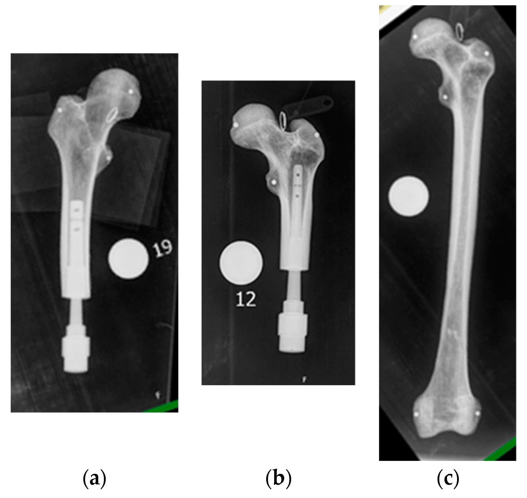
Bone anchored prosthesis: The external limb prosthesis fixation of the amputation trunk bone with special implant remains increasingly popular (Figure 2). Its major advantage over traditional prosthesis is its much more stable fixation, improved motion, and so on. Thanks to the stable fixation in the bone, osseoperception, or the patient’s susceptibility to vibration in the prosthetic structure, is improved [25,26,27]. This shows the prerequisites for using an implant as a channel between a vibration actuator and a patient. However, there are a number of conditions that hinder the development of a universal actuator:
  • External prosthetic structures have different masses, components, loading conditions, etc.
  • External prostheses are made individually for each patient.
  • Amputation stumps for each patient have different masses, bone lengths, diameters, and densities Figure 2a–c.
Rehabilitation device construction should be made of materials with low vibration damping. If a rehabilitation device has a large total mass, it is necessary to create a vibration contour to provide a signal to its user (the part of the structure that is in contact with the patient). It would not be necessary to generate vibrations in the whole the construction, as this would require an increase in both actuator power and corresponding dimensions.

1.7. Kinds of Vibration Actuators

Vibrations are mechanical oscillations initiated by any movement. However, the particular application fields require that the generators of vibrations be electrically excited. There are two groups of such actuators: Electromagnetic and piezoelectric. Briefly, they are described in Table 3. As can be seen from this table, simple electromagnetic devices like eccentric motors and electromagnets are usually not capable of simultaneously adjusting their frequency and magnitude of oscillations. In turn, the piezoelectric linear and rotation actuators requires rather high operation voltage [28,29] at a higher frequency of generated vibrations that is not allowed by standards—for wheelchairs, for example [30]. As such, the preferable type of vibration actuators is that of voce-coil motors, which, in fact, are loudspeakers without an intrinsic membrane (that has to be attached externally to produce sound). This means that the application area of such devices is acoustics but not the generation of vibrations. An analysis of the actuators, presented on the market, has shown that they cannot be easily adopted to the generation of vibration or to the sensitivity range of a particular person. They are also rather expensive and not very efficient devices. The last statement practically means that they are heavy and bulky (not compact). In this research, authors suggest to improve the parameters of the voce-coil motors with the help of 3D printing, making them suitable for use in the vibration-based diagnostic systems of prosthetic implants and pseudo-bionic feedbacks.

2. Hypothesis, Methods and Technical Assumptions

2.1. Hypothesis

The input voltage of an electromagnetic actuator is distributed according to the following equation, representing the Kirchhoff’s voltage law for the winding of the actuator
v I N ( t ) = v R ( t ) + v L ( t ) + e ( t )
where vIN(t) is the input excitation voltage, applied to the actuator, vR(t) is voltage drop over equivalent active resistance, vL(t) is dynamic voltage add-on due to inductive inertia, and e(t) is electromotive force. The first component represents real energy losses in electrical parts of the actuator, the second is the current damping element, and the third represents the energy spent in the mechanical part of the actuator or the actual energy-producing vibrations.
For the most actuators (voice coil) presented on the market, the voltage distribution is closer to an “acoustic” pattern—a significant frequency changes across equivalent resistance and inductance. This research is based on the hypothesis that the use of 3D printing in conjunction with high quality permanent magnets allows for the increase of the third component of this equation, thus achieving better efficiency and smaller size. Moreover, with 3D printing technology, it is possible to develop an actuator with individually composed frequency characteristics.

2.2. Construction of Electromagnetic Vibration Actuator

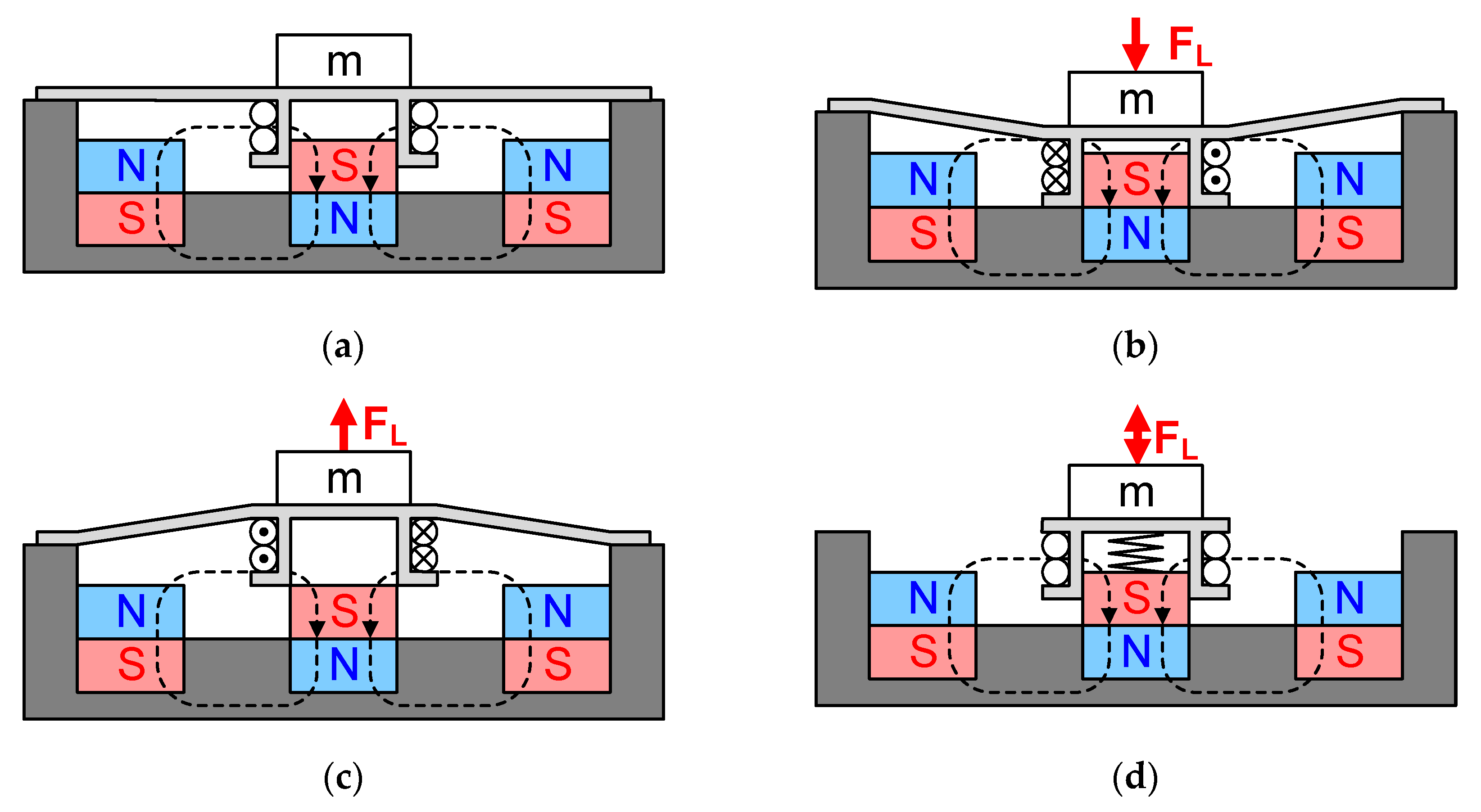
The structure of the proposed vibration actuator and details of its operation are explained in Figure 3. The actuator consisted of two parts. The first part, stationary one, emphasized in Figure 3a as dark grey shape, formed a compartment for two permanent magnets (colored): External toroidal and internal cylindrical. The second part of the actuator, moving one, was a bobbin with coil, of which top part also served as a membrane. Both parts were 3D printed on non-magnetic material. As such, the electro-magnetic part of the actuator was presented by the coil and magnets, and the mechanical part was presented by the spring and mass. At the positive current in the coil, Figure 3b, Lorentz force attracted the bobbin closer to the stationary part of the actuator. When the current was negative, Figure 3c, Lorentz force pushed the bobbin outside. Since the membrane was rather small, it did not produce pressure oscillations and may be regarded as a spring, Figure 3d. It was also assumed that the gravitation force wa negligible compared with the force produced by the coil or spring (membrane).

2.3. Mathematical Model of Electromagnetic Vibration Actuator

In order to verify the hypothesis of the research, it was necessary to find how the parameters of the actuator (Figure 3) affect its characteristics. This, in turn, required building a mathematical model of the actuator. The first equation of the model can be derived from Equation (2) when taking into account the Ohm law for the voltage drop over equivalent active resistance:
v R ( t ) = R × i ( t ) .
Self-induced back e.m.f. of a coil:
v L ( t ) = L × d i ( t ) d t .
e.m.f. induced in a moving conductor:
e ( t ) = B × l × v ( t )
where R is the equivalent resistance of the actuator, L is its inductance, l is the length of winding, and v(t) is the velocity of vertical movement of the winding/coil that was found as the derivative of its vertical displacement x
v ( t ) = d x ( t ) d t .
It is assumed that B is the density of magnetic flux generated by permanent magnets, installed in the actuator. In turn, the length of the winding l is proportional to the diameter of the coil D and number of turns n
l = n × π × D
Applying Equations (2)–(6) in Equation (1) gives the differential equation of the electrical part of the actuator:
v I N ( t ) = R × i ( t ) + L × d i ( t ) d t + B × l × v ( t ) .
One more equation describes the balance of forces applied to the moving part of the actuator:
f L ( t ) = f S P ( t ) + f M ( t ) + f D ( t )
where fL(t) is the Lorentz force for the conductor with current i(t), defined as
f L ( t ) = B × l × i ( t ) .
Below, fSP(t) is the reaction of the membrane (spring) proportional to its deformation, equal to the vertical displacement x, and proportional to its stiffness coefficient:
f S P ( t ) = k × x ( t ) .
In turn, fM(t) is the force spent to accelerate the coil, membrane, and extra weight of common mass m:
f M ( t ) = m × ( d 2 x ( t ) d t 2 + g 9.8 ) ,
but fD(t) is the damping component representing all mechanical (friction) losses expressed as:
f D ( t ) = D F × d x ( t ) d t .
Equations (8) and (9)–(12) produce the second, mechanical, differential equation of the of the actuator:
B × l × i ( t ) = k × x ( t ) + m × ( d 2 x ( t ) d t 2 + g 9.8 ) + D F × d x ( t ) d t .
Taking into account the sinusoidal input voltage vIN(t) of frequency f,
v I N ( t ) = V M × s i n ( 2 × π × f × t ) ,
which produces the following ODE (ordinary differential equation) system of the actuator
{ V M × s i n ( 2 × π × f × t ) = R × i ( t ) + L × d i ( t ) d t + B × l × v ( t ) B × l × i ( t ) = m × ( d 2 x ( t ) d t 2 + g 9.8 ) + D F × d x ( t ) d t + k × x ( t ) .
Considering the definition of velocity,
v ( t ) = d x ( t ) d t
allows for the rewriting of (15) in the form of Cauchy
{ d i ( t ) d t = R L × i ( t ) B × l × v ( t ) L + V M × s i n ( 2 × π × f × t ) d v ( t ) d t = B × l × i ( t ) m D F × v ( t ) k m × x ( t ) g 9.8 d x ( t ) d t = v ( t ) ,
which simplifies numerical solution of (15).

2.4. Technical Assumptions

Producing the actuator with the help of 3D printing of mostly non-magnetic materials allowed for the making of several assumptions:
(1)
The inductance of coil L calculated as coreless coil that significantly reduces its value;
(2)
defining the dimensions of the moving part allows for the use of thicker wires with lower R;
(3)
the orientation of the actuator and gravitation g9.8 can be ignored if the stiffness of the membrane is high enough to keep the mechanical operation on the linearity range;
(4)
the above stated considerations makes the electrical constant of the system much lower than the mechanical one (as it take place in the case of electrical motors, etc.), which allows for the simplification of (15) and (17) into a single 2nd order ODE:
F L m × s i n ( s i n ( 2 × π × f × t + φ ) = m × d 2 x ( t ) d t 2 + D F × d x ( t ) d t + k × x ( t )
where in the tentatively obtained Equation (18) describes a damped spring pendulum system where the frequency of oscillations depends on the stiffness of the membrane (spring) k and accelerated mass m as
f = 1 2 × π × k m .
Therefore, the actuator must produce maximal output at this frequency. Additionally, the possibility of changing its frequency response affecting k and m looks realistic. Below, these assumptions are analyzed and verified experimentally.

3. 3-D Printed of Vibration Actuators and their Initial Evaluation

To test our hypothesis, two methods were used. In the first method, a computer model was used with the specified parameters of real actuators. The second method was the direct measurement of real actuators. Three different actuators were selected for the measurement: An industrial actuator as a control test, Figure 4a, an actuator with a wide membrane (large actuator), Figure 4c, and an actuator with a small membrane (small actuator), Figure 4b. The test setup consisted of an actuator indirectly controlled from a computer. The measured vibration acceleration data were returned to the computer. To coordinate, the computer and the actuator used a special system: An analog discovery kit (ADK) [31]. The installation of such allowed for the analysis of the amplitude frequency response. However, the ADK was not capable of generating a high power signal. To solve this problem, a standard D-type amplifier was installed at the output of the ADK generator. The vibroacceleration signal was measured using an analog accelerometer adxl335 [32]; adxl335 was connected directly to the input of the oscilloscope of the ADK. To control the ADK and the subsequent signal processing, the special software Waveforms was used [33].
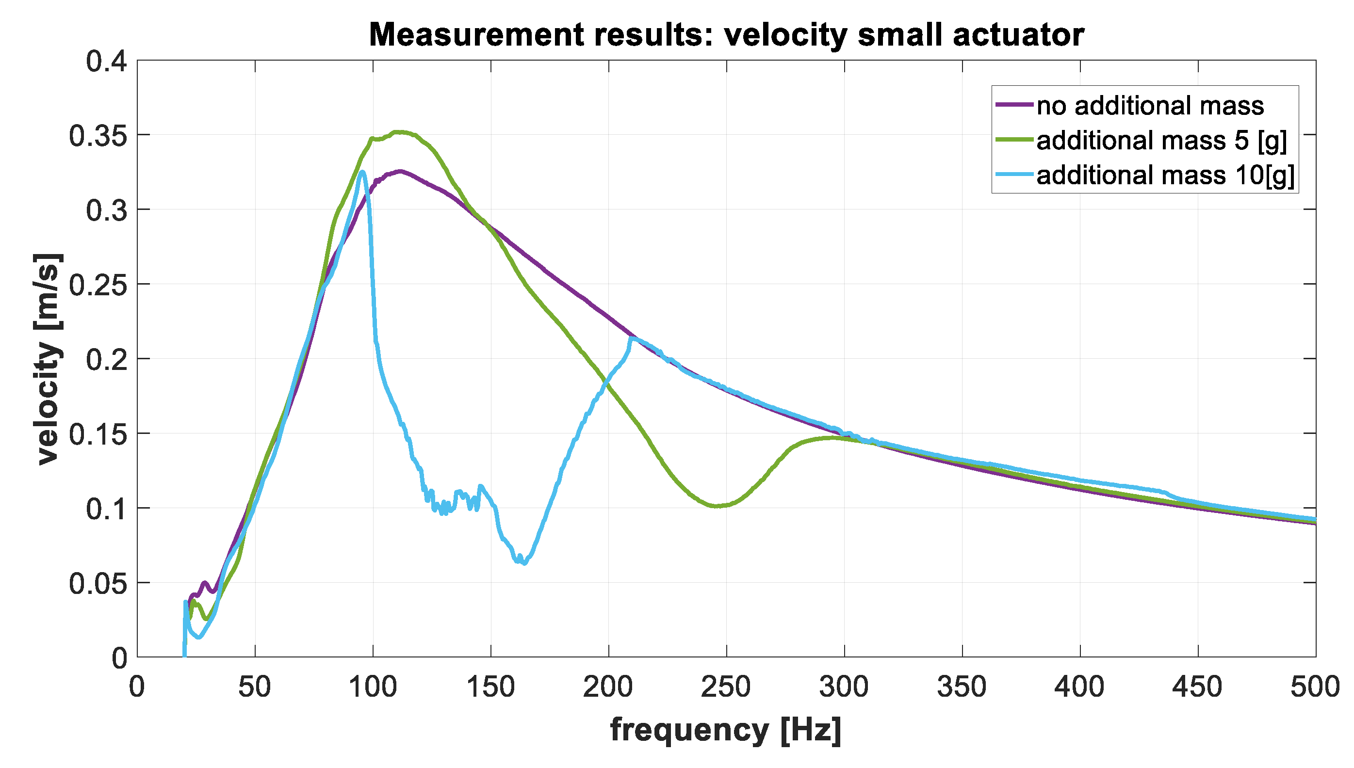
For each actuator, vibration acceleration measurements without additional mass and with additional weights 5 (g) and 10 (g) were carried out. The measurements were carried out for all axes of the accelerometer three times. The measured values of each axis were averaged, and the absolute value of the vibration acceleration was calculated using:
a = x 2 + y 2 + z 2
where x, y, and z are measured and averaged signals of each accelerometer axis. Then acceleration value was integrated to get vibration velocity. The electrical and mechanical parameters of the vibration actuator, to simulate in the Matlab environment was measured, and shown in Table 4.
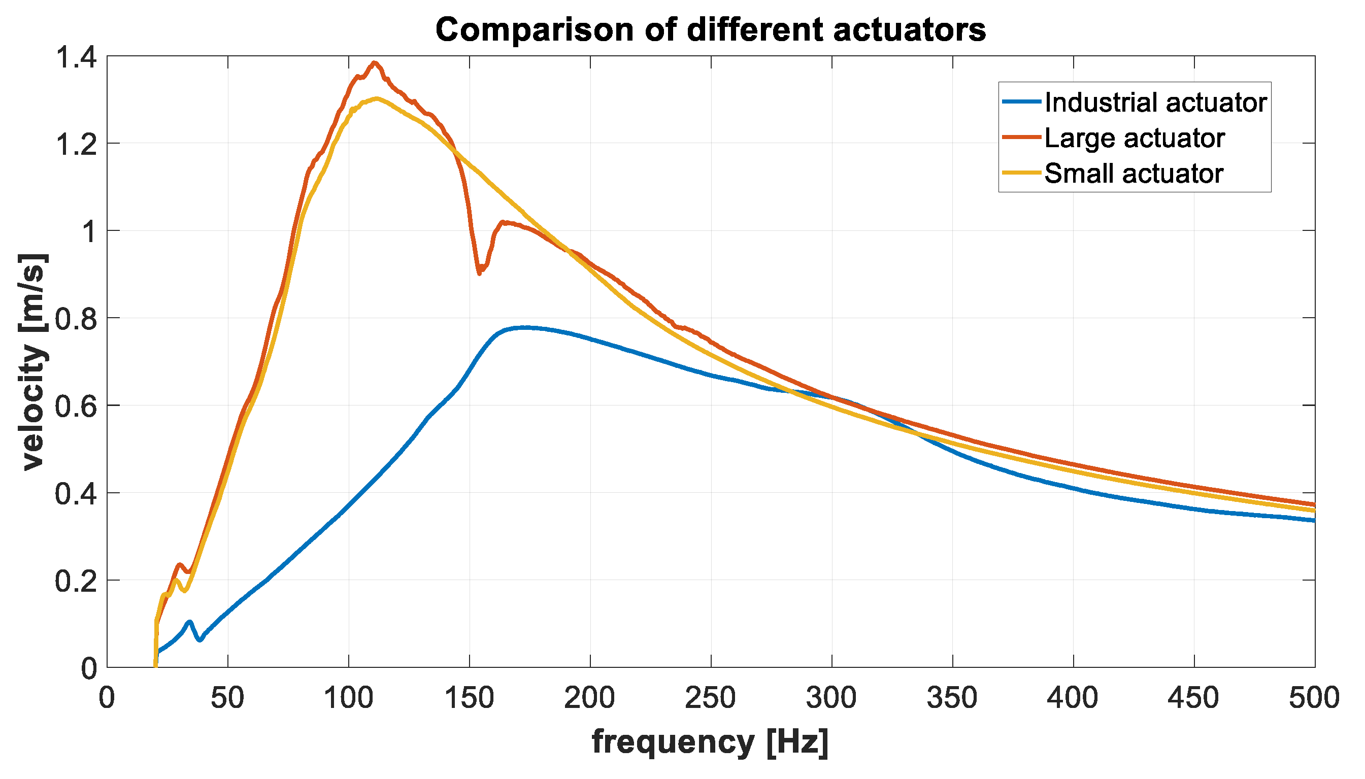
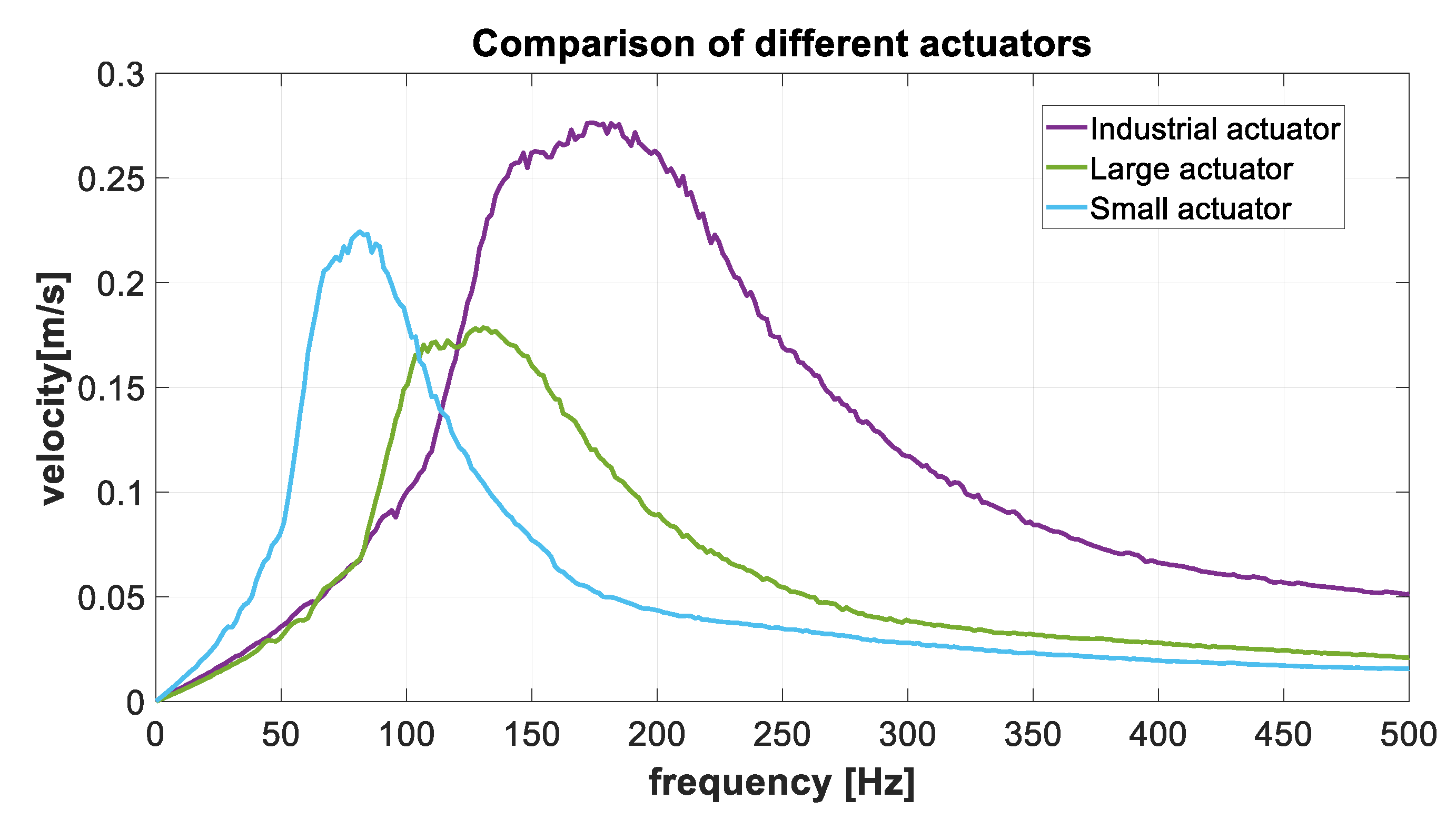
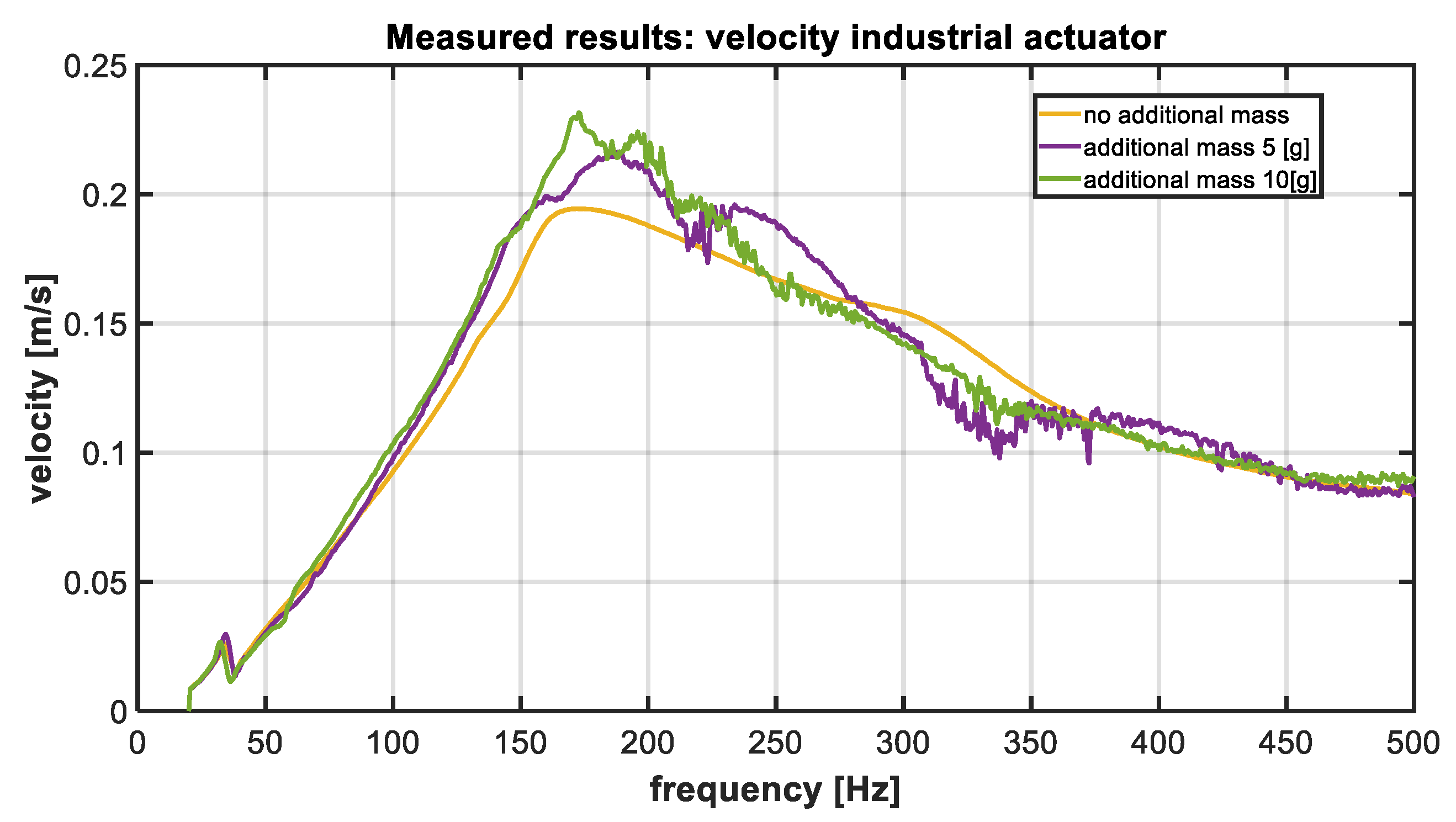
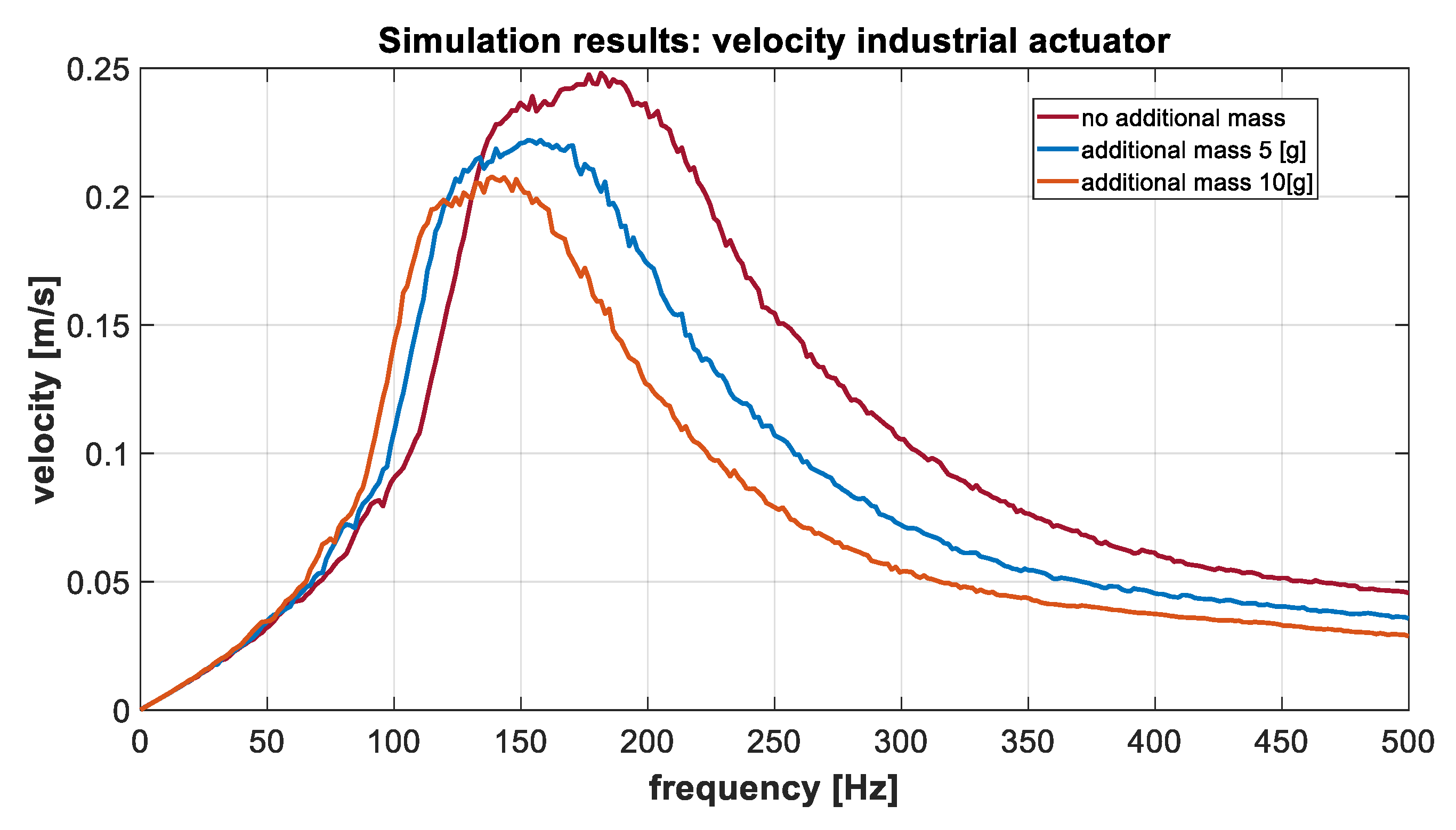
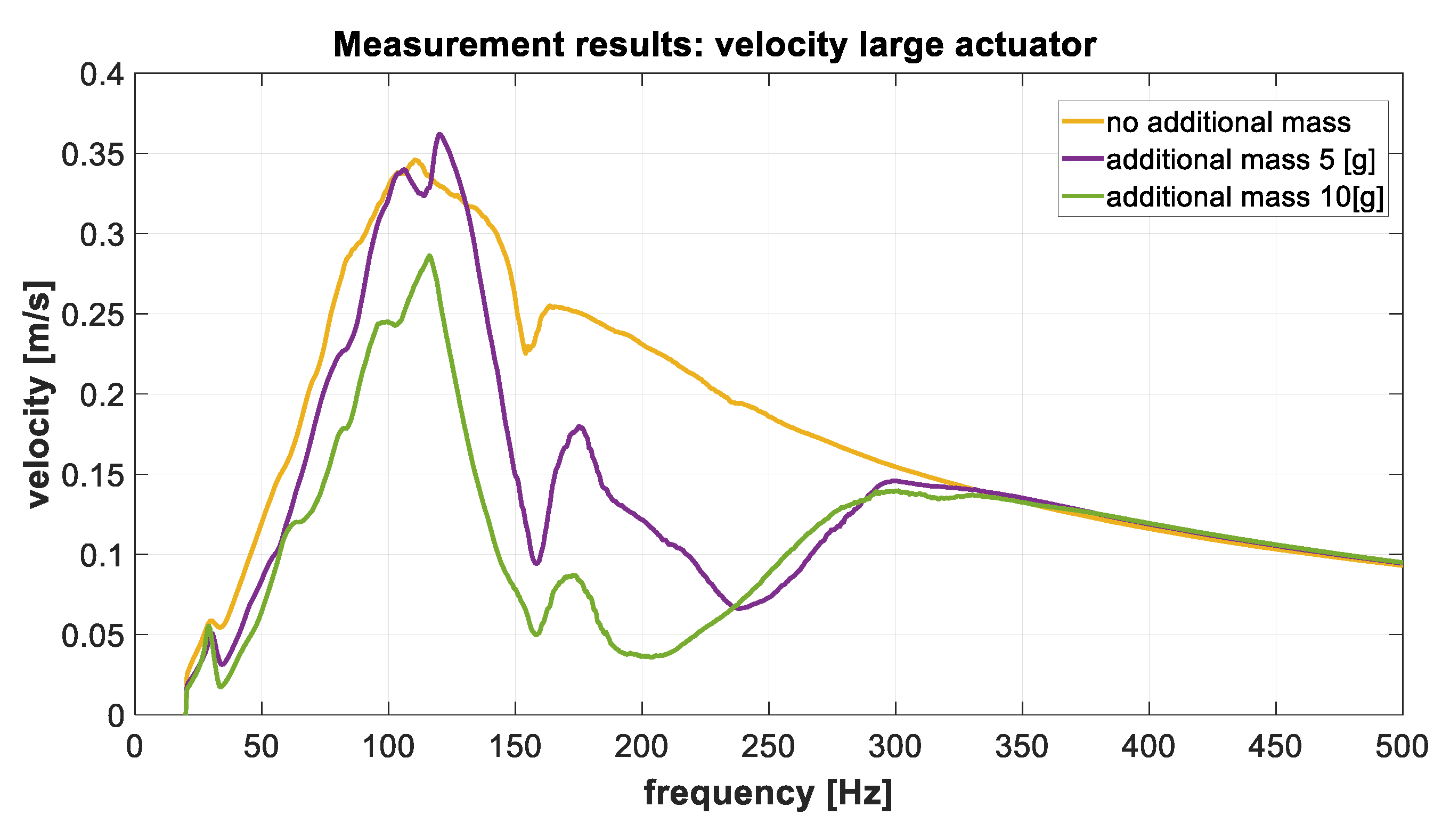
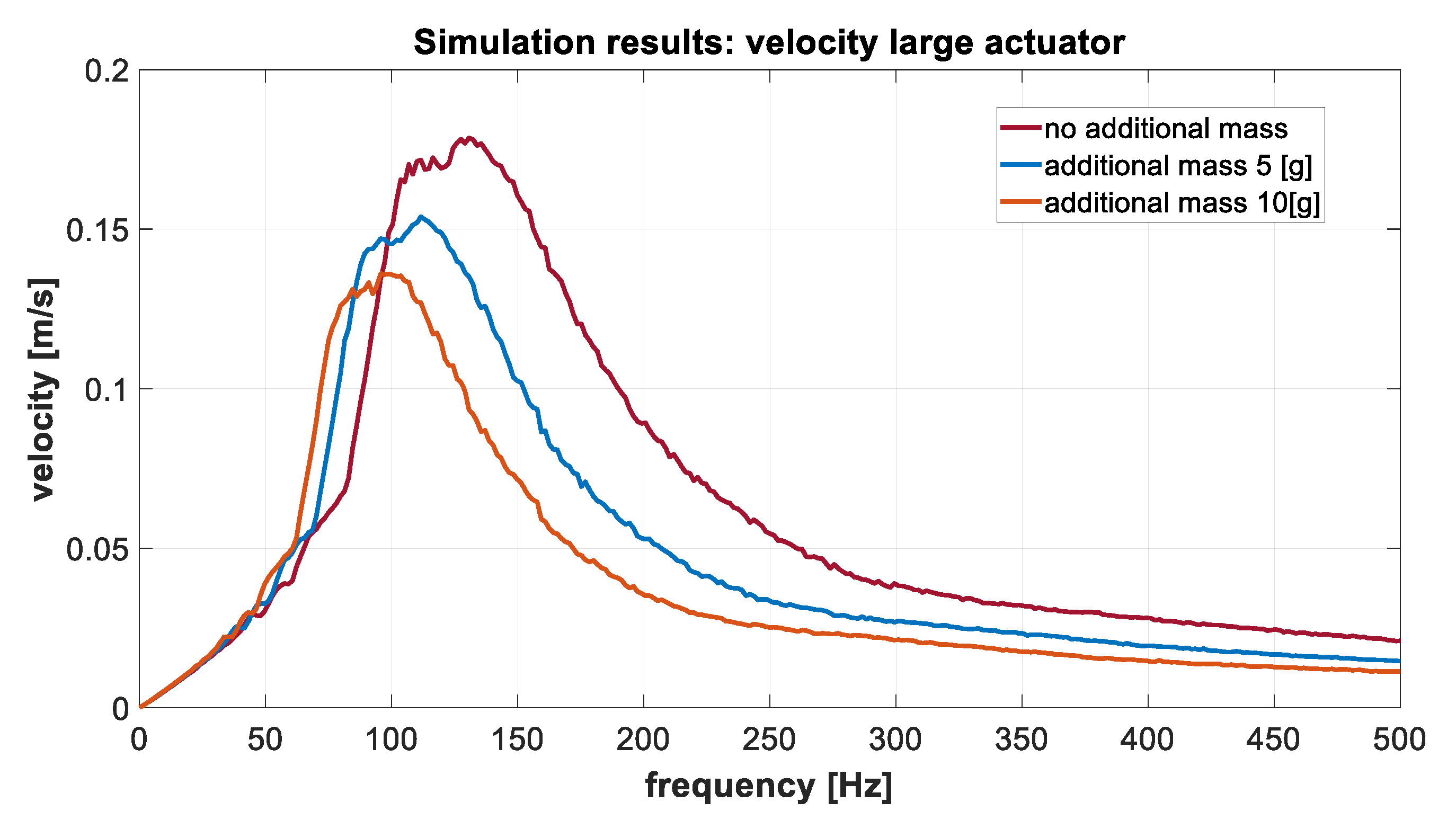
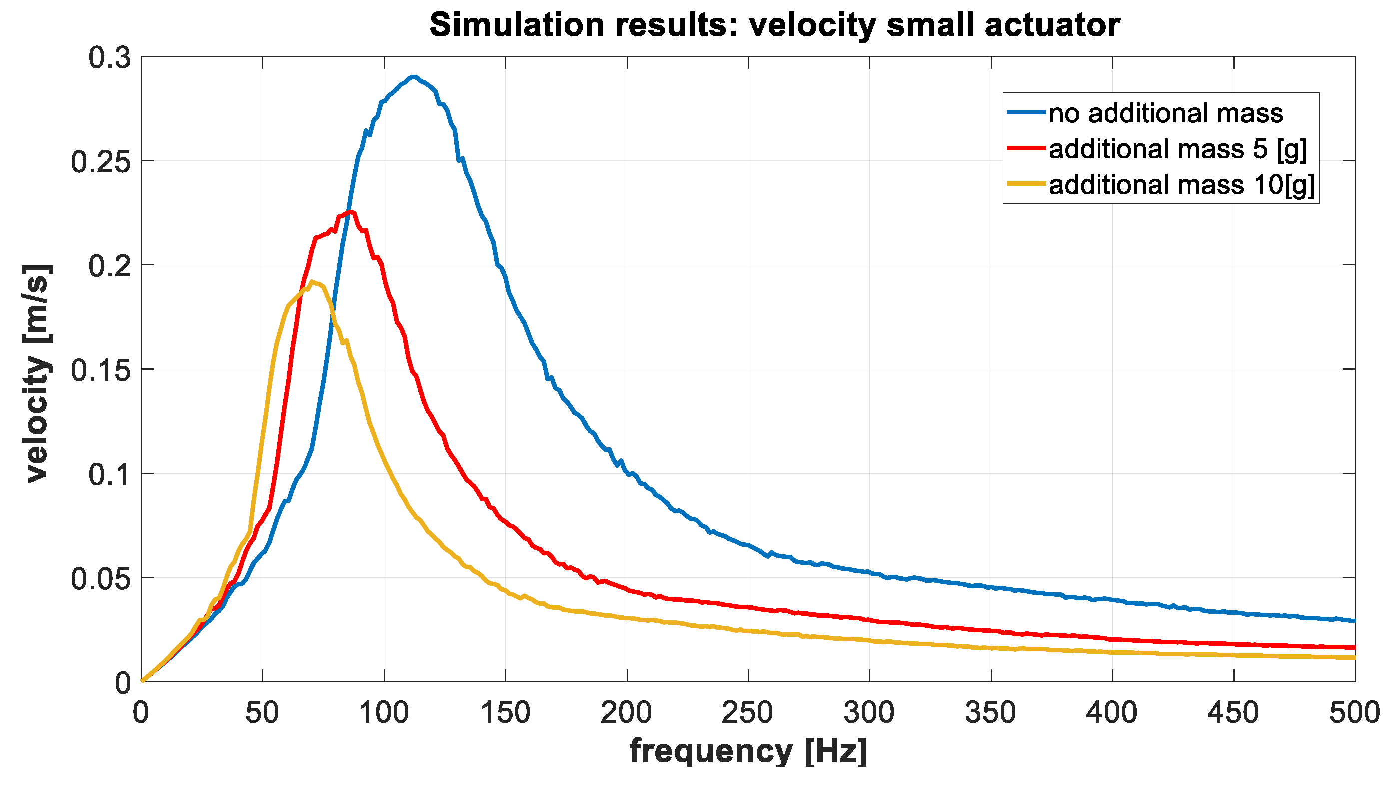
In Figure 5, the measured displacement of different kind actuators are shown. Figure 6 shows simulation parameters based on same actuator characteristics. Differences appeared because of the non-ideal boundary parameters of the measurements. Strong dependence existed in the stiffness ratio of the membranes due to its influence on the magnitude and frequency of the vibration signal. The frequency value increased and the amplitude value decreased proportionally to the stiffness of the membrane. Figure 7, Figure 8, Figure 9, Figure 10, Figure 11 and Figure 12 show the results of measurements and simulation using different mass values. For almost all actuators, the frequency signal decreased and the magnitude signal decreased proportionally to mass. The printed actuators appeared to have some additional resonances. The reason for these resonances was the low mass of the printed actuator. This led to more complex interactions in the system.

4. Discussion on the Combined 3D Printed Design of Vibration Actuators

4.1. Comparative Evaluation of Existing and Proposed 3D Printed Vibration Actuators

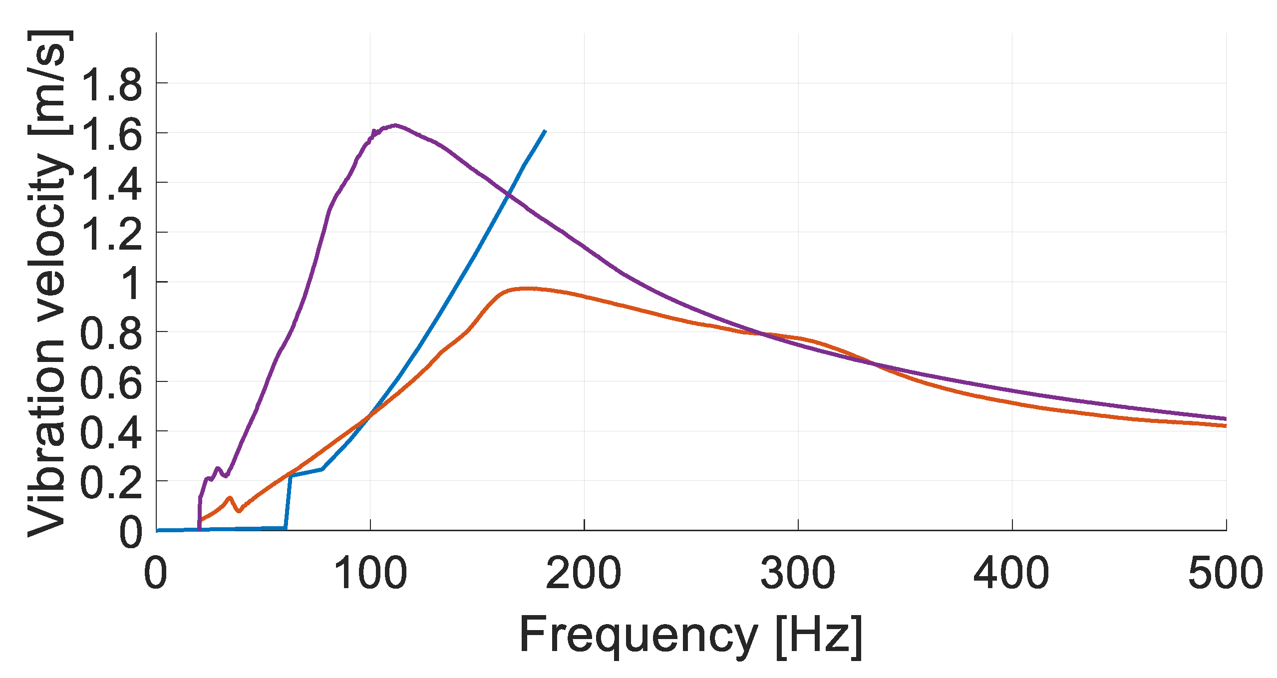
In order to compare the existing and proposed 3D printed vibration actuators, their frequency characteristics are presented together in Figure 13. As can be found from this figure, the most available eccentric rotating mass vibration actuators (blue curve) showed a linear dependence of the mechanical output on the frequency or provided maximal output at the maximal applicable frequency. In practice, this means that in a particular mechanical configuration of prosthesis or rehabilitation unit, such actuators will under-generate or over-generate vibrations.
Quite rare alternative actuators of other types (voice coil motor-derived—orange curve) provide maximal mechanical output at the frequency which corresponds to the mechanical resonance of this particular actuator, according to the Equations (18) and (19). This leads to the same consequences—in the case of particular configuration of prosthesis, they under-generate or over-generate vibrations.
The frequency response of the “small” 3D printed actuator developed within the project is presented as a violet curve. As it can be seen in this figure, it had a maximum output at the resonant frequency. As such, at a glance, it looks that the contribution of 3D printing technology is only quantitative—it allows for the perfect matching of particular requirements and actual performance of a produced actuator. However, in the last case, the maximum pints were not occasional—the actuators were dedicated for the operation at the pre-selected frequency and intensity. Moreover, the same 3D printing technology allows for the making of an actuator with an adjustable stiffness of its membrane and attached mass, thus achieving variable resonant points and the real-time modification of the frequency response.
The logical conclusion that follows from the above-mentioned considerations is that necessary designs must include an electrically/electronically reconfigurable membrane.

4.2. Combining of Developed 3D Printed Vibration Actuators in a Single S/W Configurable Design

Equation (19) shows that the resonant frequency of the 3D printed actuator depends on the equivalent stiffness of the actuator—which includes the actual stiffness of the membrane and the stiffness of the object—where the actuator is attached. It is difficult to predict this last factor. For this reason, there exists a significant difference between the simulated/calculated value of the resonant frequency and the experimentally measured one. Another factor influencing the resonant frequency is the equivalent mass of the attached actuator movement part. It is even more difficult to predict this parameter, and this uncertainty also leads to a difference between the calculated and experimentally measured values of the resonant frequency. In the given analysis, however, it is important that both these factors affect resonant frequency. Since equivalent mass is less predictable but stiffness is easier to modify, it seems more suitable for use in a prospective vibration generator with a real-time adjustable frequency response. The outlines of the design of the prospective adjustable vibration generator, following the corresponding actuators of fixed stiffness from Figure 4b,c, are presented in Figure 14. The membranes of the mentioned actuators had four fastening points. In each “fixed” actuator, they were located at the required distance from the support that provided the necessary stiffness of the membrane. In the proposed “variable” design, the distance of fastening points could be modified with the help of variable distances of the supports of the fastening points. Figure 14a shows the configuration with longest distance between the support point and center of equivalent mass that led to a membrane that was more flexible and had a higher resonant frequency. In turn, Figure 14c shows the actuator with shortest distance, a more rigid membrane, and a lower frequency. Two versions of the “adjustable” actuator were proposed: Mechanically configured and electronically configured. In the mechanically configured version, fastening was made with the help of a screw, but in the electronically configured version, fastening is made with the metal rod driven by an electromagnet.
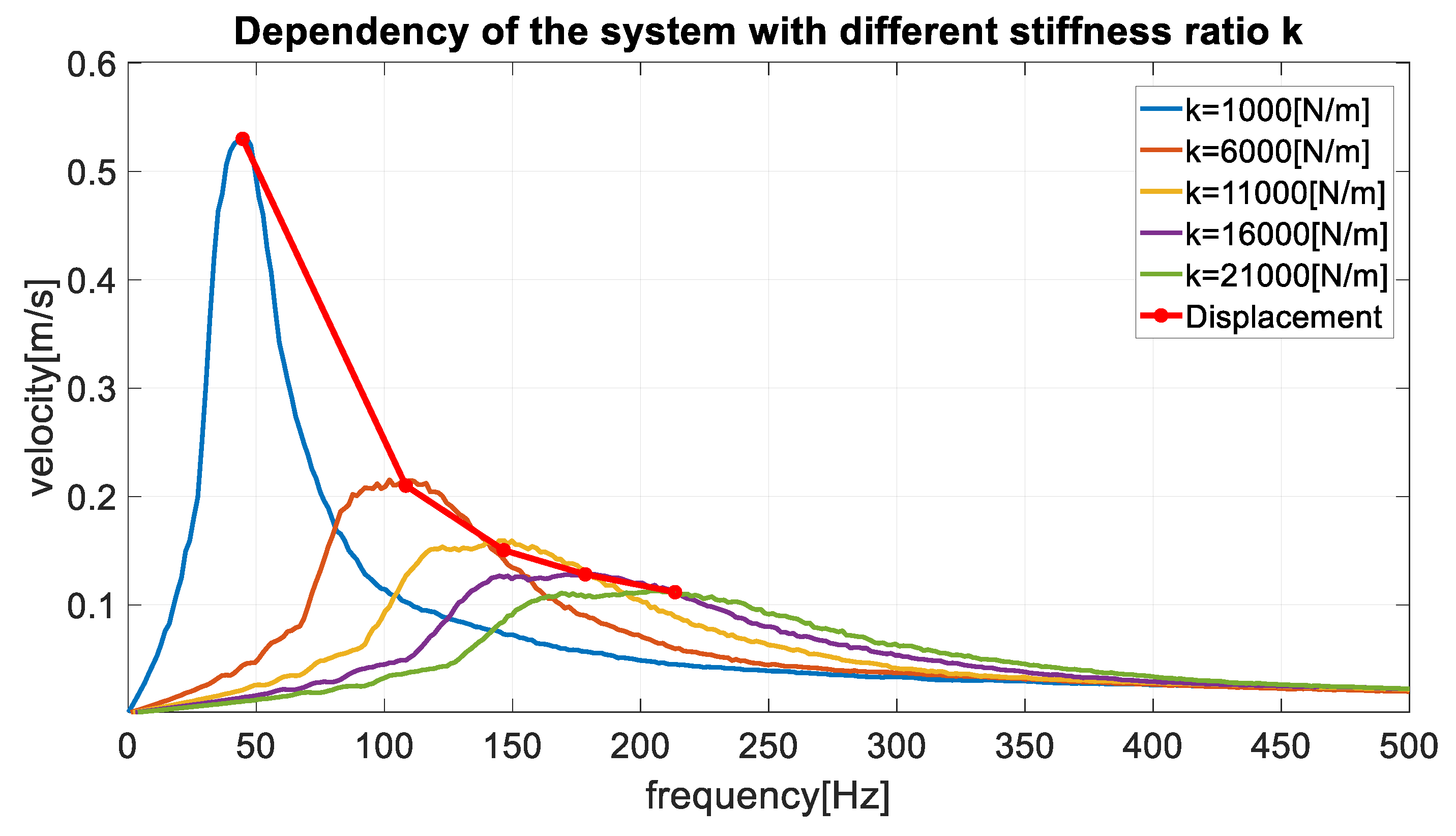
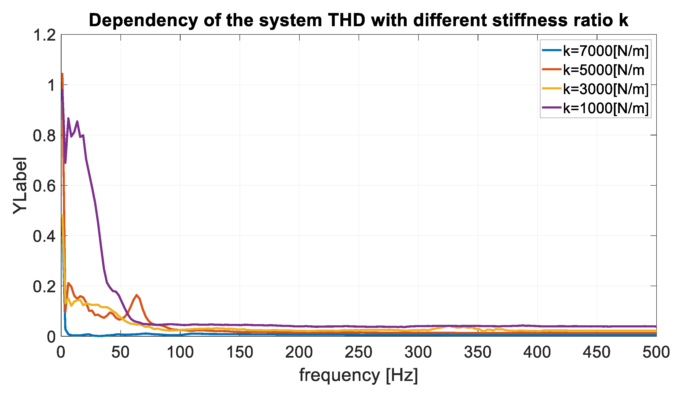
In order to verify the operation principles of the “adjustable” actuator, its equivalent Matlab script model was built. The model was based on the above mentioned equations. All electrical parameters of the adjustable vibration generator were similar to the large actuator (Table 4). The mechanical part had the following variable stiffness parameters: k = 1000 (N/m), k = 3000 (N/m), k = 5000 (N/m), and k = 7000 (N/m). The corresponding simulation results are presented in Figure 15, the violet, orange, red, and blue curves represent the frequency responses of a fixed stiffness membrane. The dynamic changes of velocity depended on the stiffness ratio. In turn, the red curve corresponds to the adjustable actuator. In this case, the control system of the actuator always chose the membrane configuration that produced the maximal mechanical output at the considered frequency. It can be seen that the resulting curve provides the maximal mechanical output for a range of frequencies—not for a frequency point. Therefore, the actuator was capable of providing the required vibrations at various different configurations of the prosthetic devices (the necessity of operation in different mechanical environments was explained previously in Section 1.5). To verify the simulation results of the adjustable actuator, a real actuator was printed with a 3D printer. The measured results are presented in Figure 16. For output quality signal verification, the total harmonic distortion ratio was measured in different frequency values (Figure 17).

5. Discussion and Conclusions

The simulation data, experimental data, and data about 3D manufacturing process obtained within the research, confirm the above hypothesis. It is possible to make several conclusions based on this data:
(1)
The simulation with the obtained mathematical model and experiments showed that the point of maximal power output depended on the stiffness coefficient of the membrane of the proposed vibration actuator, as well as on the mass attached to the membrane; the influence of these parameters corresponds to Equation (19) if taking into account measurement declinations;
(2)
the provided data about consumed materials and energy, permanent magnets, auxiliary components (required for fastening, connecting, etc.), and invested labor manufacturing confirm that the design of the actuator can be easily modified for a particular frequency at which the power output is maximal; that maximal contribution to the cost of the actuator can be made by permanent magnets;
Future works can concentrate on:
(1)
The real-time programmable modification of stiffness/mass—assuming the change of these parameters with the help of dedicated electronic equipment.
(2)
The further is reduction of the cost of actuators; since the most significant contribution to cost is made by magnets, the primary goal of such a reduction of the elaboration of other excitation in schemes, e.g., an electrodynamic scheme in which the excitation magnetic field is produced by an electromagnet.
(3)
It is necessary to agree on the mass of the base of the actuator and the membrane parameter to get rid of extra resonances.

Author Contributions

For research articles with several authors, a short paragraph specifying their individual contributions must be provided. The following statements should be used “Conceptualization, I.G. and M.V.; Methodology, M.V.; Software, M.V.; Validation, I.G., M.V. and O.G.; Formal Analysis, M.V.; Investigation, I.G., M.V., O.G. and P.S.; Resources, I.G., M.V., O.G. and P.S.; Data Curation, M.V.; Writing-Original Draft Preparation, I.G.; Writing-Review & Editing, I.G. and M.V.; Visualization, M.V. and I.G.; Supervision, I.G.; Project Administration, I.G.; Funding Acquisition, I.G.”

Funding

The preparing of this publication is supported by the joint found of Riga Technical University and Riga Stradiņš University within the contract RTU/RSU-19 “Research and Development of Pseudo-Bionic Feedbacks and Diagnostics Systems for Prosthetic and Rehabilitation Devices”.

Conflicts of Interest

The authors declare no conflict of interest.

References

  1. Sowe, S.K.; Simmon, E.; Zettsu, K.; de Vaulx, F.; Bojanova, I. Cyber-Physical-Human Systems: Putting People in the Loop. IT Prof. 2016, 18, 10–13. [Google Scholar] [CrossRef] [PubMed]
  2. Serpanos, D. The Cyber-Physical Systems Revolution. Computer 2018, 51, 70–73. [Google Scholar] [CrossRef]
  3. Stoker, C.R.; Burch, D.R.; Hine, B.P.; Barry, J. Antarctic undersea exploration using a robotic submarine with a telepresence user interface. IEEE Expert 1995, 10, 14–23. [Google Scholar] [CrossRef]
  4. Iborra, A.; Pastor, J.A.; Alvarez, B.; Fernandez, C.; Merono, J.M.F. Robots in radioactive environments. IEEE Robot. Autom. Mag. 2003, 10, 12–22. [Google Scholar] [CrossRef]
  5. Utsumi, M.; Hirabayashi, T.; Yoshie, M. Development for teleoperation underwater grasping system in unclear environment. In Proceedings of the 2002 Internnational Symposium on Underwater Technology (Cat. No.02EX556), Tokyo, Japan, 19 April 2002; pp. 349–353. [Google Scholar]
  6. Radi, M.; Nitsch, V. Telepresence in Industrial Applications: Implementation Issues for Assembly Tasks. Presence Teleoperators Virtual Environ. 2010, 19, 415–429. [Google Scholar] [CrossRef]
  7. Hagn, U.; Ortmaier, T.; Konietschke, R.; Kubler, B.; Seibold, U.; Tobergte, A.; Nickl, M.; Jorg, S.; Hirzinger, G. Telemanipulator for remote minimally invasive surgery. IEEE Robot. Autom. Mag. 2008, 15, 28–38. [Google Scholar] [CrossRef]
  8. Mayer, H.; Nagy, I.; Knoll, A.; Braun, E.U.; Bauernschmitt, R.; Lange, R. Haptic Feedback in a Telepresence System for Endoscopic Heart Surgery. Presence Teleoperators Virtual Environ. 2007, 16, 459–470. [Google Scholar] [CrossRef] [Green Version]
  9. Chen, Y.; Mazumdar, A.; Brooks, C.F.; Van Bloemen Waanders, B.G.; Bond, S.D.; Nemer, M.B. Remote Distributed Vibration Sensing Through Opaque Media Using Permanent Magnets. IEEE Trans. Magn. 2018, 54, 1–13. [Google Scholar] [CrossRef]
  10. Lim, W.Q.; Zhang, D.H.; Zhou, J.H.; Belgi, P.H.; Chan, H.L. Vibration-based fault diagnostic platform for rotary machines. In Proceedings of the IECON 2010—36th Annual Conference on IEEE Industrial Electronics Society, Glendale, AZ, USA, 7–10 November 2010; pp. 1404–1409. [Google Scholar] [CrossRef]
  11. Gai, V.E. Method of diagnostics of the state of rolling element bearing on the basis of the theory of active perception. In Proceedings of the 2014 International Conference on Mechanical Engineering, Automation and Control Systems (MEACS), Tomsk, Russia, 16–18 October 2014; pp. 1–4. [Google Scholar] [CrossRef]
  12. Vaimann, T.; Sobra, J.; Belahcen, A.; Rassõlkin, A.; Rolak, M.; Kallaste, A. Induction machine fault detection using smartphone recorded audible noise. IET Sci. Meas. Technol. 2018, 12, 554–560. [Google Scholar] [CrossRef] [Green Version]
  13. Climente-Alarcon, V.; Antonino-Daviu, J.A.; Vedreño-Santos, F.; Puche-Panadero, R. Vibration Transient Detection of Broken Rotor Bars by PSH Sidebands. IEEE Trans. Ind. Appl. 2013, 49, 2576–2582. [Google Scholar] [CrossRef]
  14. Stone, G.C. Condition monitoring and diagnostics of motor and stator windings—A review. IEEE Trans. Dielectr. Electr. Insul. 2013, 20, 2073–2080. [Google Scholar] [CrossRef]
  15. Procházka, P. Methods and Facilities for Calibration of Noncontact Blade Vibration Diagnostic Systems. IEEE Trans. Instrum. Meas. 2018, 67, 2345–2352. [Google Scholar] [CrossRef]
  16. Boloznev, V.V.; Mirsaitov, F.N.; Noskov, V.Y. Signal and noise characteristics of autodynes in solving problems of gas-turbine engine vibration-based diagnostics. In Proceedings of the 2014 24th International Crimean Conference Microwave and Telecommunication Technology, Sevastopol, Ukraine, 7–13 September 2014; pp. 1019–1022. [Google Scholar] [CrossRef]
  17. Secic, A.; Kuzle, I. Audio-based On-Load Tap Changer diagnostics: correlation of sound and vibration fingerprints. In Proceedings of the 2018 International Symposium on Industrial Electronics (INDEL), Banja Luka, Bosnia and Herzegovina, 1–3 November 2018; pp. 1–6. [Google Scholar] [CrossRef]
  18. Zizins-Malisevs, S.; Poiss, G. Power transformer mechanical condition assessment with a vibration-based diagnostic method. In Proceedings of the 2015 56th International Scientific Conference on Power and Electrical Engineering of Riga Technical University (RTUCON), Riga, Latvia, 14 October 2015; pp. 1–4. [Google Scholar] [CrossRef]
  19. Trendafilova, I.; Cartmell, M.P.; Ostachowicz, W. Vibration-based damage detection in an aircraft wing scaled model using principal component analysis and pattern recognition. J. Sound Vib. 2008, 313, 560–566, ISSN 0022-460X. [Google Scholar] [CrossRef] [Green Version]
  20. Heirich, O.; Steingass, A.; Lehner, A.; Strang, T. Velocity and location information from onboard vibration measurements of rail vehicles. In Proceedings of the 16th International Conference on Information Fusion, Istanbul, Turkey, 9–12 July 2013; pp. 1835–1840. [Google Scholar]
  21. Vinet, L.; Zhedanov, A. Engineering Haptic Devices; Springer: London, UK, 2014; Volume 44. [Google Scholar]
  22. Afzal, M.R.; Oh, M.K.; Lee, C.H.; Park, Y.S.; Yoon, J. A Portable Gait Asymmetry Rehabilitation System for Individuals with Stroke Using a Vibrotactile Feedback. BioMed Res. Int. 2015, 2015, 16. [Google Scholar] [CrossRef] [PubMed]
  23. Kingma, H.; Felipe, L.; Gerards, M.C.; Gerits, P.; Guinand, N.; Perez-Fornos, A.; Demkin, V.; Van de Berg, R. Vibrotactile feedback improves balance and mobility in patients with severe bilateral vestibular loss. J. Neurol. 2018, 265, 1–8. [Google Scholar]
  24. Chen, B.; Feng, Y.; Wang, Q. Combining Vibrotactile Feedback with Volitional Myoelectric Control for Robotic Transtibial Prostheses. Front. Neurorobot. 2016, 10, 8. [Google Scholar] [CrossRef] [PubMed]
  25. Technical Committee CEN/TC 293. European Standard prEN 12184:2004: Electrically Powered Wheelchairs, Scooters and Their Chargers-Requirements and Test Methods; European Standard: Brussels, Belgium, 2004. [Google Scholar]
  26. Hägström, E.; Hagberg, K.; Rydevik, B.; Brånemark, R. Vibrotactile evaluation: Osseointegrated versus socket-suspended transfemoral prostheses. J. Rehabil. Res. Dev. 2013, 50, 1423–1434. [Google Scholar] [CrossRef] [PubMed]
  27. Jacobs, R.; Brånemark, R.; Olmarker, K.; Rydevik, B.; Steenberghe, D.V.; Brånemark, P.I. Evaluation of the psychophysical detection threshold level for vibrotactile and pressure stimulation of prosthetic limbs using bone anchorage or soft tissue support. Prosthet. Orthot. Int. 2000, 24, 133–142. [Google Scholar] [CrossRef] [PubMed] [Green Version]
  28. Uchino, K. Piezoelectric ultrasonic motors: Overview. Smart Mater. Struct. 1998, 7, 273–285. [Google Scholar] [CrossRef]
  29. Belly, C.; Porchez, T.; Bagot, M.; Claeyssen, F. Improvement of Linear and Rotative Stepping Piezo Actuators using design and control. In Proceedings of the ACTUATOR2012, 13th International Conference on New Actuators, Bremen, Germany, 18–20 June 2012; pp. 246–249. [Google Scholar]
  30. Rowe, M.J.; Tracey, D.J.; Mahns, D.A.; Sahai, V.; Ivanusic, J.J. Mechanosensory Perception: Are There Contributions from Bone-Associated Receptors? In Proceedings of the Symposium From Osseointegration to Osseoperception: The Functional Translation, (December 2003), Sydney, Australia, 24 February 2005; pp. 100–108. [Google Scholar]
  31. Available online: https://analogdiscovery.com/ (accessed on 19 March 2019).
  32. Available online: https://reference.digilentinc.com/reference/software/waveforms/waveforms-3/start (accessed on 19 March 2019).
  33. Available online: https://www.analog.com/media/en/technical-documentation/data-sheets/adxl335.pdf (accessed on 19 March 2019).
Figure 1. Use of vibration in orthopedic systems: (a) Human–machine–human interaction; (b) diagnostic system.
Electronics 08 00810 g001
Figure 2. Two different femur X-ray after osteointegration: (a) The residual femur is long, and its osteointegrated stem has a diameter of 19 mm; (b) the residual femur is short, and it osteointegrated stem has a diameter of 12 mm; (c) normal femur for comparison.
Electronics 08 00810 g002
Figure 3. Structure of the proposed vibration generator: (a) Not energized; (b) attracting force; (c) buoyant force; and (d) equivalent scheme with spring.
Electronics 08 00810 g003
Figure 4. Design of vibration actuator: Industrial (a), small (b), and large (c).
Electronics 08 00810 g004
Figure 5. Comparison of measured displacement values for different actuators.
Electronics 08 00810 g005
Figure 6. Simulation velocity values for different actuators.
Electronics 08 00810 g006
Figure 7. Mass influence on industrial actuator measured data.
Electronics 08 00810 g007
Figure 8. Mass influence on industrial actuator simulation data.
Electronics 08 00810 g008
Figure 9. Influence on large actuator measured data.
Electronics 08 00810 g009
Figure 10. Influence on large actuator simulation data.
Electronics 08 00810 g010
Figure 11. Influence on small actuator measured data.
Electronics 08 00810 g011
Figure 12. Influence on small actuator simulation data.
Electronics 08 00810 g012
Figure 13. Comparison of experimentally measured characteristics (frequency response) of the commercially available and proposed actuators absolute values.
Electronics 08 00810 g013
Figure 14. Structure of the proposed adjustable vibration generator: (a) Flexible configuration; (b) average flexibility; and (c) rigid configuration.
Electronics 08 00810 g014
Figure 15. Results of simulation of adjustable vibration generator.
Electronics 08 00810 g015
Figure 16. Results of measurement of adjustable vibration generator.
Electronics 08 00810 g016
Figure 17. Results of measurement of adjustable vibration generator THD (total harmonic distortion).
Electronics 08 00810 g017
Table 1. Cells sensitive to haptic stimulus.
Cell (Mechanoreceptor)AdaptationPerception Area Sensitivityf (Hz)Sensitive to
Merkel disk (SA-I)SlowSmallDistinct0–50Texture/pressure
Ruffini endings (SA-II)SlowLargeDiffuse0–20Texture/pressure
Meissner corpuscle (RA-I)RapidSmallDistinct10–50Vibration
Pacinian corpuscle (RA-II)RapidLargeDiffuse40–1000Vibration
Table 2. Parameters of prosthetic and rehabilitation devices.
Nr.Rehabilitation Device GoupsWeight (kg)
1.Prostheses of Upper Extremities0.5–3 kg
2.Prostheses of Lower Extremities Above knee prostheses
Below knee prostheses
3–7 kg
1–3 kg
3.Crutches0.5–1 kg
4.Rollators and walking in a frame1.5–5 kg
5.Wheelchairs without electric drive8–25 kg
6.Wheelchairs with electric drive–100 kg
Table 3. Cells sensitive to haptic stimulus.
TypeIndependent Control ofOther Remarks
FrequencyMagnitude
Eccentric motorOnly togetherMost available
Linear motors+-
Electromagnets+-
Voice coil motors++On market or acoustics (high impedance)
Piezoelectric linear++High voltage required [28]
Piezoelectric rotation++High voltage required [29]
Table 4. Parameters of vibroactuators.
Small ActuatorLarge ActuatorIndustrial Actuator
Membrane mass (kg)0.002030.003060.00793
Foot mass (kg)0.000630.000630.00656
Base mass (kg)0.019410.029200.22700
Accelerometer mass (kg)0.004000.004000.00400
Membrane stiffness (N/m)3184163921345
Resistance (Ω)4.324.503.57
Inductance (µH)157.20166.80675.00
Induction (T)0.230.200.65
Damping ratio (N/m2)1.541.201.74
Length of wire (m)444