Article

A Multi-Inductor H Bridge Fault Current Limiter

1
Electrical Engineering Department, Amirkabir University of Technology, 15875-4413 Tehran, Iran
2
Electrical Engineering Department, Aeronautical University of Science and Technology, 15914 Tehran, Iran
3
Department of System Engineering and Automatic Control, University of Seville, 41004 Seville, Spain
4
Management and Production Technologies of Northern Aveiro—ESAN, Estrada do Cercal 449, Santiago de Riba-Ul, 3720-509 Oliveira de Azeméis, Portugal
5
Department of Electrical Engineering and Automation, Aalto University, 02150 Espoo, Finland
*
Authors to whom correspondence should be addressed.
Electronics 2019, 8(7), 795; https://doi.org/10.3390/electronics8070795
Submission received: 18 May 2019 / Revised: 28 June 2019 / Accepted: 12 July 2019 / Published: 16 July 2019
(This article belongs to the Special Issue Industrial Applications of Power Electronics)

Abstract

:
Current power systems will suffer from increasing pressure as a result of an upsurge in demand and will experience an ever-growing penetration of distributed power generation, which are factors that will contribute to a higher of incidence fault current levels. Fault current limiters (FCLs) are key power electronic devices. They are able to limit the prospective fault current without completely disconnecting in cases in which a fault occurs, for instance, in a power transmission grid. This paper proposes a new type of FCL capable of fault current limiting in two steps. In this way, the FCLs’ power electronic switches experience significantly less stress and their overall performance will significantly increase. The proposed device is essentially a controllable H bridge type fault current limiter (HBFCL) that is comprised of two variable inductances, which operate to reduce current of main switch in the first stage of current limiting. In the next step, the main switch can limit the fault current while it becomes open. Simulation studies are carried out using MATLAB and its prototype setup is built and tested. The comparison of experimental and simulation results indicates that the proposed HBFCL is a promising solution to address protection issues.

1. Introduction

The immense global growth in energy demand will require additional power generation as well as an efficient, reliable complex meshed power distribution. The existing power grids will experience, in the near future, a growing burden due to an upsurge in electricity demand and will experience an ever-growing penetration of distributed power generation, which are factors that will contribute to a higher incidence of fault current levels. The massive growth of gird interconnection and integration of distributed generators (DGs) increase the network fault current level [1,2,3,4]. The solid-state fault current limiter (FCL) is a fast protection device that includes a DC reactor and solid-state switches [1,2,3,4]. The voltage source converters (VSCs) of HVDC systems are sensitive to the fault current. Recently, they have been combined with appropriate FCLs to protect them [5,6]. There are other types of FCLs that have been introduced in the literature. A resistive superconductor FCL based on variable resistance, which is very complex and costly, has been presented in the works of [7,8]. The bridge type FCLs based on DC reactor have been studied in the literature [9,10,11,12]. The AC/DC reactor based FCL has been presented in the work of [13]. In this FCL, two-stage operation decreases the voltage stress on the solid-state switches. The other well-known FCL type are the resonance type FCLs, which have high transient voltage, and this is their most important challenge [14,15]. A series two-stage FCL that behaves by operation of the solid-state switch in the secondary winding is introduced in the works of [16,17]. Saturated core FCL based on DC bias saturation and the series coil is studied in the literature [18,19,20,21,22,23,24]. In this type, the electronic switch connects to DC saturation current and does not have any conflict with the line current. Superconductive FCLs have been investigated for limiting the fault current in the microgrid [25,26]. FCLs can preserve microgrid from AC grid fault currents because the AC/DC microgrid should be protected in both the AC and DC sides [27]. Novel types of magnetic based FCLs are analyzed in the works of [28,29] to improve the performance of FCL for a power grid. Flux coupled FCLs and bridge type solid-state FCLs [30,31] are used to design a novel H bridge type fault current limiter (HBFCL).
The rest of this paper is organized as follows. In Section 2, the HBFCL structure is presented. In Section 3, the analytical studies are given and, in the next section, the simulation results of the proposed HBFCL are presented. In Section 5, the experimental test results are presented and, finally, the conclusion is drawn.

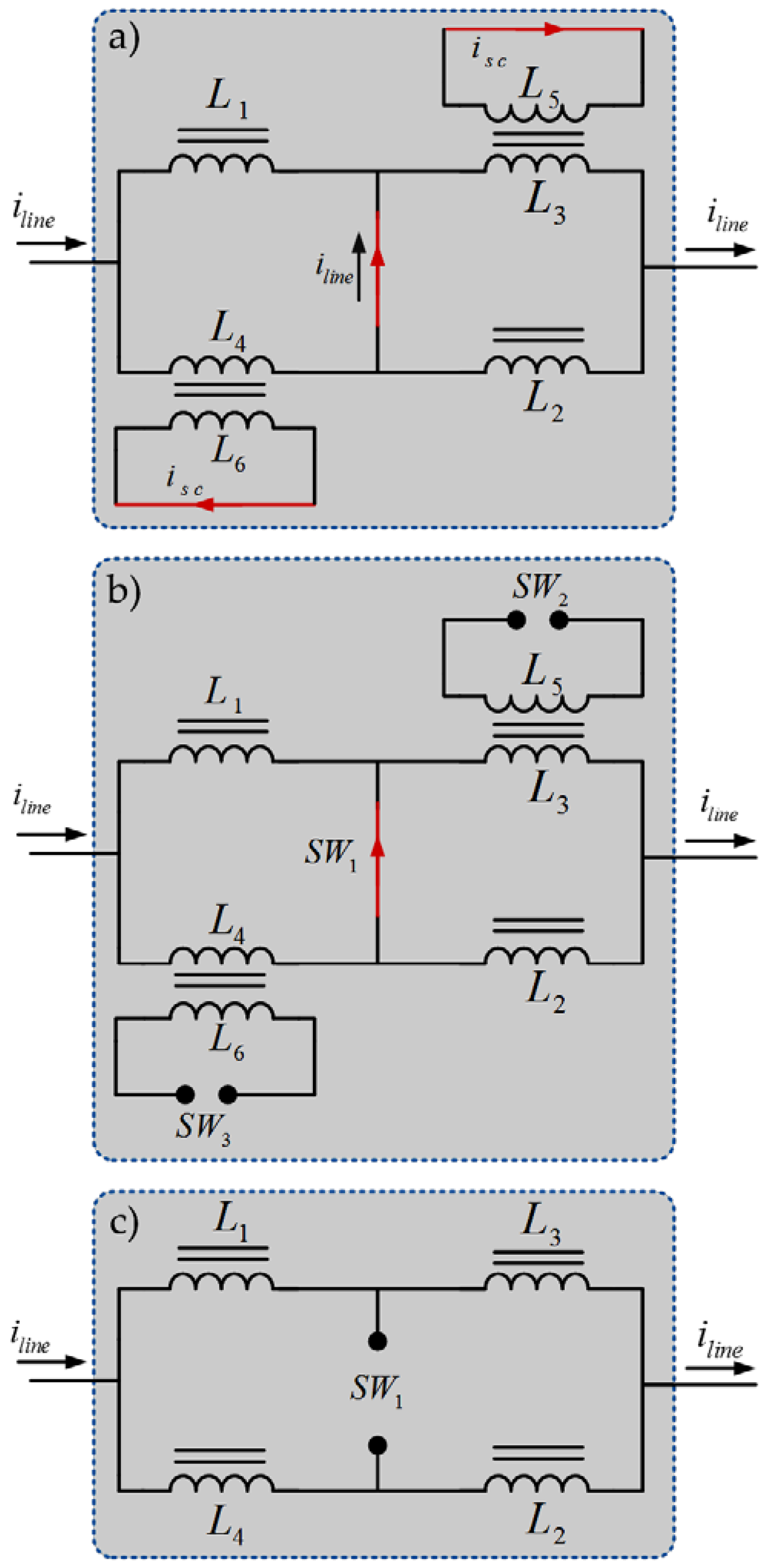
2. Proposed HBFCL Configuration

The proposed HBFCL is connected in series with the line to protect the point of common coupling (PCC) of the microgrid against the fault current. The HBFCL includes four inductors, L1–L4, as shown in Figure 1. An antiparallel power electronic IGBTs, that is, G1 and G2, are connected as main switches to the middle branch of the H bridge. L3 and L4 are coupled with L5 and L6, respectively. The power electronic switch, G3 and G4, and rectifier diodes, D1–D4, are connected to these coupled inductances. After switching of IGBT switches (G3 and G4), L5 and L6 are bypassed and two levels for L3 and L4 in the different modes are configured.
The operation of the proposed FCL is divided into three modes, as shown in Figure 2. Figure 2a–c show the HBFCL equivalent circuit during the normal operation mode after fault occurrences and during the fault limiting mode, respectively.

2.1. Normal Operation Mode

In this mode, as shown in Figure 2a, the secondary sides of L3 and L4 are short-circuited via IGBTs and the inductors are modeled by their leakage inductance and a small resistance. Considering L1 and L2 values, high inductive current is carried by L3, L4, G1, and G2. During the normal operation mode, all of the IGBT switches are in ON state and the maximum power flow is passed by the HBFCL.

2.2. Pre-Limiting Mode

After fault occurrence, the IGBTs G3 and G4 become turned-off and the main breaker SW1, which includes series antiparallel switches that is shown as G1, and G2 change to turned-off state. In the off state of G3 and G4, the inductance of L3 and L4 increases and the current of the main switch, that is, SW1, decreases to a low value. Figure 2b shows the equivalent circuit of the pre-limiting mode.

2.3. Fault Current Limiting Mode

In this mode, the current of the SW1 decreases and it can safely be opened. In this case, the limited fault current is divided between two parallel branches, which include series connection of L1, L3 and L2, L4.

3. Analytical Studies

3.1. Steady-State Mode

Analytical studies are presented based on the three operation states of the proposed HBFCL. In the first state, there is no fault in the system. In this case, the microgrid equivalent circuit is shown in Figure 2a and the analytical study is done according to this circuit. In this case, the current and voltage is sinusoidal and we have the following:
i l i n e = V S Z S + Z H B F C L + Z l i n e + R f a u l t ,
where
Z H B F C L = ( r 3 + r 4 ) + j ( X L 3 + X L 4 ) ,
V H B F C L = i l i n e ( ( r 3 + r 4 ) + j ( X L 3 + X L 4 ) ) ,
and
V P C C = V S i l i n e ( ( r 3 + r 4 ) + j ( X L 3 + X L 4 ) + Z S ) ,
where Vs, VHBFCL, VPCC are source voltage, HBFCL voltage drop, and voltage of point of common coupling, respectively. iline is line current. LL3, LL4, r3, and r4 are leakage inductances and resistances of L3 and L4, respectively. Zs, ZHBFCL, and Zline are impedances of the source, HBFCL, and line, respectively. Rfault is resistance of the fault.
During normal operation, the power loss is calculated with Equation (5).
P l o s s = P C u ( L 3 ) + P C u ( L 4 ) + P C u ( L 5 ) + P C u ( L 6 ) + P S W 1 + P S W 2 + P S W 3 ,
where
P C u = i l i n e 2 × r 3 + i l i n e 2 × r 4 + i s c 2 × r 5 + i s c 2 × r 6 ,
P S W = i l i n e × V S W 1 + 2 ( i s c × V S W 2 ) .
The power loss depends directly on the line current, inductor secondary current, switching voltage, and coil resistance.
According to Equations (5)–(7), the HBFCL power loss is negligible by decreasing coil resistance and using the series power IGBT switch.

3.2. Pre-Fault Limiting Mode

In fault occurrence, G3 and G4 change the H bridge topology and limit the fault current, and we have the following equation.
X L 1 × X L 2 = X L 3 × X L 4 = ( 2 π f ) 2 L 1 × L 2 = ( 2 π f ) 2 L 3 × L 4 ,
where XL1 to XL4 are reactor impedances while the secondary side is open-circuited and f is the network frequency.

3.3. Fault Current Limiting Dynamic Mode

Considering Figure 2c, we have the following equations:
2 L 1 = L 2 ,   2 L 4 = L 3 ,   L = L 1 = L 4 ,
L H B F C L = ( L 1 + L 3 ) ( L 2 + L 4 ) ( L 1 + L 3 ) + ( L 2 + L 4 ) = 3 2 L ,
and
V S ( t ) + i l i n e r e q + ( L e q ) d i l i n e d t = 0 ,
and in which
i l i n e ( t ) = A e r e q L e q t + B V m sin ( ω t θ ) ,
where A and B are determined based on initial condition.
r e q = r S + r l i n e + r H B F C L + R f a u l t
L e q = L S + L l i n e + 3 2 L

4. Control Strategy

Figure 3 shows the control system block diagram based on the proposed HBFCL.
In this system, represented by the HBFCL control block diagram from Figure 3, the current and voltage signals are monitored via current and voltage transformers are measured and send to a digital (A/D) sampler to make the digital data. In fault cases, the current rate is raised and the rms value of the current is compared with the reference value, that is, 1.2 p.u. The voltage signal is sampled by the A/D block and its rms value is compared with the reference voltage. A step generator drives IGBT switches. The main switches are driven after a very small delay to meet the HBFCL self-protection and limit the fault current in two steps. After fault current limitation, a timer resets the step generator to turn-on G1G4 for checking the fault clearance.

5. Simulation Results

In this section, simulation results are carried out considering the system configuration shown in Figure 1. The electrical network parameters are listed in Table 1.
In order to be able to monitor the fault cases, the line to ground fault is applied to the network and the proposed HBFCL is connected in series in the line. To verify the proposed HBFCL effectiveness, two cases are considered to obtain the simulation results, that is, fault current without HBFCL effect and limited fault current with HBFCL effect, as shown in the following subsections.

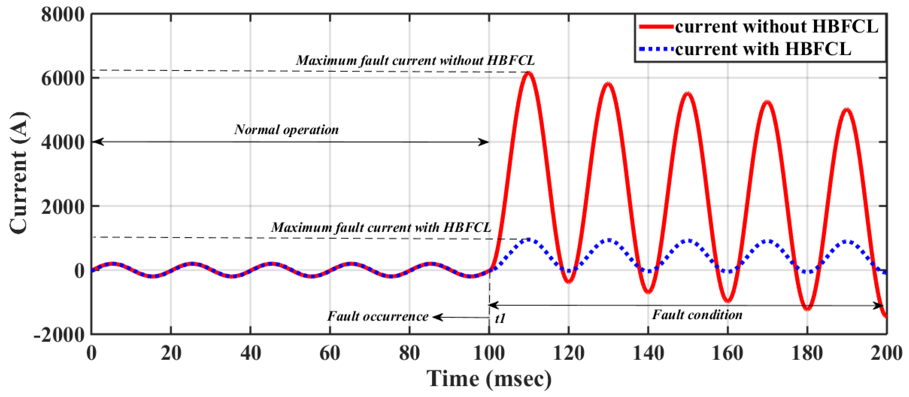
5.1. Fault Condition without HBFCL Effect

In this section, the proposed electrical system shown in Figure 1 is simulated without the HBFCL effect. Figure 4 shows the line current provided by the main feeder during the normal and fault operation modes. During the normal operation mode, the line current amplitude is 200 A till t1. After fault occurrences in t1, the fault current is increased and its first peak amplitude reaches 6300 A. Accordingly, if bus bar base current assumes 1000 A fault first peak is 6.1 p.u, which shows studied bus-bar high strength and high possible fault current.
As shown in Figure 5, the PCC voltage has 20 kV amplitude during the normal operation mode, and after fault occurrences, its amplitude experiences deep voltage sag and decreases to 10 kV.

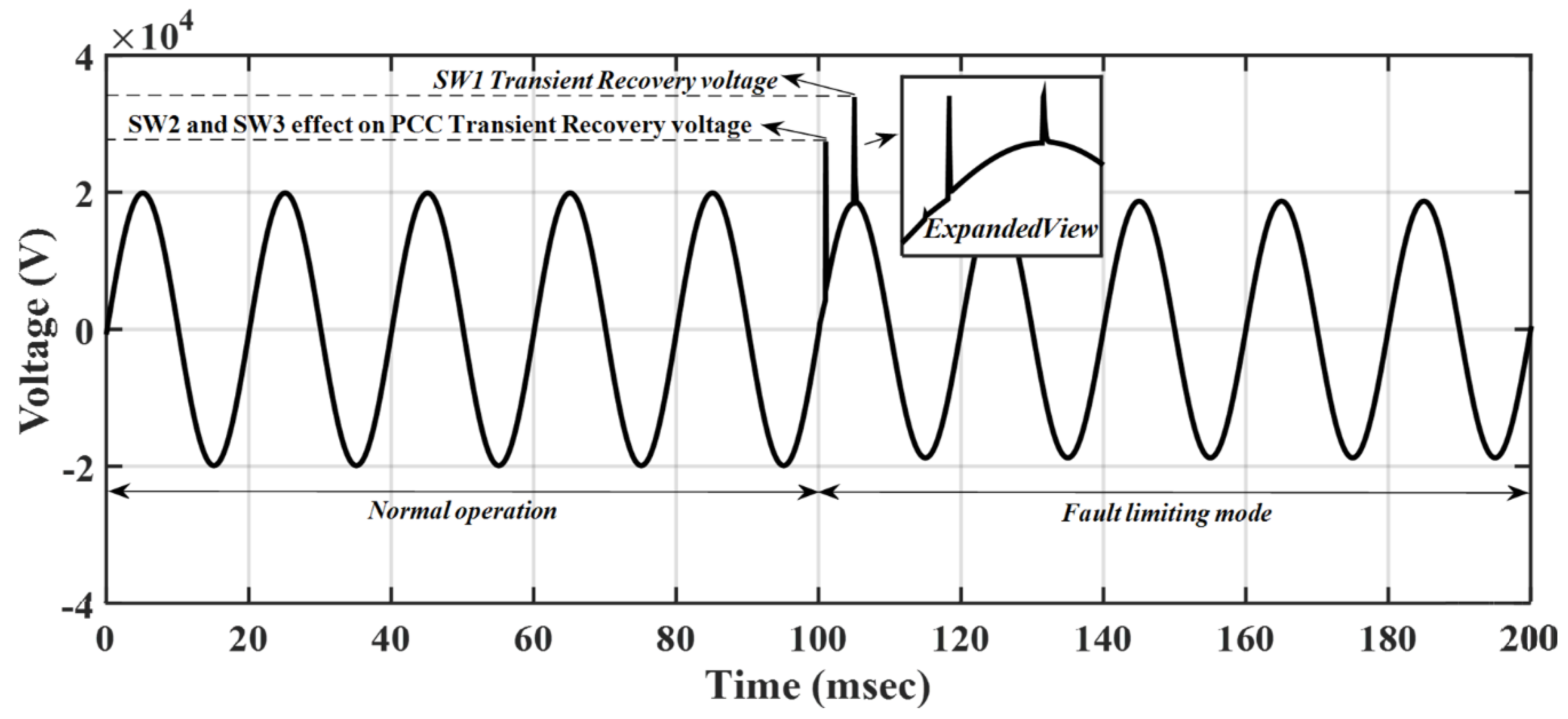
5.2. Fault Condition with HBFCL Effect

Connecting the proposed HBFCL as a protection device to the line, the fault current is decreased to an acceptable level, as shown in Figure 6.
In order to control the fault current, IGBTs change the HBFCL topology in two steps. In t1, 100 ms fault is occurred while between t1 and t2, 102 ms HBFCL control system recognizes the fault but HBFCL is not operated. In t2, SW2 and SW3 are turned off and current is limited by increasing L1 and L2 impedance, as shown in Figure 6a. After a small delay, the main switch SW1 is turned off and current is decreased to nominal current. Considering the HBFCL limiting strategy, the first peak of the fault current is limited to 1 kA. Figure 6b shows the PCC voltage during normal, transient, and fault states. Considering the switching transient recovery voltage (TRV) between t2 and t3, the TRV peak has an acceptable rate in the first switching and second switching; it is damped very well for safe switching action.
In Figure 7, it is possible to observe the SW2 and SW3 effect on the PCC transient recovery voltage and the SW1 transient recovery voltage after the 100 ms instant, in which a transition from the normal operating mode to the fault limiting mode can be observed. This effect can also be observed in more detail in the expanded view of Figure 7.
Figure 8 shows the limited fault current by HBFCL where the first peak of the fault current is decreased considerably.

6. Simulation Results

In this section, the laboratory test prototype is built and tested to verify the simulation results. The parameters values are listed in Table 2 and the proposed prototype is shown in Figure 9.
The prototype shown in Figure 9 includes four inductors created by E-I 56 core and 0.5 mm2 wire. Core saturation has occurred in approximately 6 A, which is out of the test range. The IGBTs with part number (STGP10NC60H) as an SW1 and SW3 are used in the prototype structure. The control circuit is made by NODE MCU hardware and it has independent current and voltage sensors. This hardware sends the proper pulses to IGBTs via drivers. An autotransformer is used as an electrical source and a variable resistance is used as an electrical load. The line to ground fault is applied by 25 A, 500 V solid-state relay.
The voltage and current signals during the normal and fault operation modes are presented in Figure 10a–c.
In Figure 10a, current waveform is shown during the normal and fault operation where the current amplitude in normal condition is 1 A. In t1, fault is applied to the setup and the line current raises and reaches 3 A. This result is in fair agreement with the simulation result shown in Figure 6a. Moreover, the main switch current is measured and considered in three states, that is, normal condition, fault pre-limiting mode, and turning off the main switch. Pre-limiting operation is carried out by SW2 and SW3 operation, which decreases the line current. The main switch is SW1 and its operation causes safe and easy current interruption. Figure 10b shows the PCC voltage profile during the normal and fault conditions. In the normal operation, PCC voltage is 24 V; after fault occurrences, the peak voltage reaches 40 V. By operating the main switch, transient voltage peak value decreases to 32 V and, after HBFCL operation, the PCC voltage is fixed to 23 V. This signal closely agreed with the simulation result shown in Figure 7. Figure 10c shows the SW1 current in fair agreement with the simulation results shown in Figure 6b.

7. Conclusions

Power systems will suffer a growing pressure as a result of an upsurge in electricity demand and an increasing penetration of distributed power generation, which will cause, in turn, a higher incidence of fault current levels. Therefore, in order to mitigate such potential problems, in this paper, a new type of FCL named H bridge fault current limiter (HBFCL) is proposed. The simulation and experimental results show the appropriate operation of the proposed HBFCL during the normal, transient, and fault conditions. Dissipation of fault energy in the four inductors and fault current limiting by three solid-state switches are a successful method that improves performance of the HBFCL. Experimental tests validate the performed simulations in this paper. They demonstrate that the PCC voltage can be successfully protected against the TRV.

Author Contributions

Conceptualization, A.M.; Methodology, K.G.; Software, H.R.; Validation, E.P.; Writing—original draft, A.H.; Writing—review and editing, K.R.; Supervision, E.M.G.R.

Funding

This research received no external funding.

Conflicts of Interest

The authors declare no conflict of interest.

References

  1. Ueda, T.; Morita, M.; Arita, H.; Kida, Y.; Kurosawa, Y.; Yamagiwa, T. Solid-sate current limiter for power distribution system. IEEE Trans. Power Deliv. 1993, 8, 1796–1801. [Google Scholar] [CrossRef]
  2. Rouzbehi, K.; Zhu, J.; Zhang, W.; Gharehpetian, G.B.; Luna, A.; Rodriguez, P. Generalized voltage droop control with inertia mimicry capability—Step towards automation of multi-terminal HVDC grids. In Proceedings of the 2015 International Conference on Renewable Energy Research and Applications (ICRERA), Palermo, Italy, 22–25 November 2015; pp. 1556–1561. [Google Scholar]
  3. Hoshino, T.; Salim, K.M.; Nishikawa, M.; Muta, I.; Nakamura, T. DC reactor effect on bridge type superconducting fault current limiter during load increasing. IEEE Trans. Appl. Supercond. 2001, 11, 1944–1947. [Google Scholar] [CrossRef]
  4. Salim, K.M.; Hoshino, T.; Nishikawa, M.; Muta, I.; Nakamura, T. Preliminary experiments on saturated DC reactor type fault current limiter. IEEE Trans. Appl. Supercond. 2002, 12, 872–875. [Google Scholar] [CrossRef]
  5. Rouzbehi, K.; Candela, J.I.; Luna, A.; Gharehpetian, G.B.; Rodriguez, P. Flexible Control of Power Flow in Multiterminal DC Grids Using DC–DC Converter. IEEE J. Emerg. Sel. Top. Power Electron. 2016, 4, 1135–1144. [Google Scholar] [CrossRef]
  6. Rouzbehi, K.; Miranian, A.; Candela, J.; Luna, A.; Rodriguez, P. Instelligent voltage control in a dc micro-grid containing PV generation and energy storage. In Proceedings of the 2014 IEEE PES T&D Conference and Exposition, Chicago, IL, USA, 14–17 April 2014; pp. 1–5. [Google Scholar]
  7. Gromoll, B.; Ries, G.; Schmidt, W.; Kraemer, H.-P.; Seebacher, B.; Utz, B.; Nies, R.; Neumueller, H.-W.; Baltzer, E.; Fischer, S.; et al. Resistive fault current limiters with YBCO films 100 kVA functional model. IEEE Trans. Appl. Supercond. 1999, 9, 656–659. [Google Scholar] [CrossRef] [Green Version]
  8. Ye, L.; Lin, L.; Juengst, K.-P. Application Studies of Superconducting Fault Current Limiters in Electric Power Systems. IEEE Trans. Appl. Supercond. 2002, 12, 900–903. [Google Scholar]
  9. Hoshino, T.; Salim, K.M.; Nishikawa, M.; Muta, I.; Nakamura, T. Proposal of saturated DC reactor type superconducting fault current limiter (SFCL). Cryogenics 2001, 41, 469–474. [Google Scholar] [CrossRef]
  10. Shfaghatian, N.; Heidary, A.; Radmanesh, H.; Rouzbehi, K. Microgrids Interconnection to Upstream AC grid Using a Dual-function Fault Current Limiter and Power Flow Controller: principle and test results. IET Energy Syst. Integr. 2019. [Google Scholar] [CrossRef]
  11. Heidary, A.; Radmanesh, H.; Bakhshi, A.; Rouzbehi, K.; Pouresmaeil, E. A Compound Current Limiter and Circuit Breaker. Electronics 2019, 5, 551. [Google Scholar] [CrossRef]
  12. Radmanesh, H.; Heidary, A.; Fathi, S.H.; Gharehpetian, G.B. Dual Function Ferroresonance and Fault Current Limiter Based on DC Reactor. IET Gener. Transm. Distrib. 2016, 10, 2058–2065. [Google Scholar] [CrossRef]
  13. Radmanesh, H.; Fathi, S.H.; Gharehpetian, G.B.; Heidary, A. Bridge-Type Solid-State Fault Current Limiter Based on AC/DC Reactor. IEEE Trans. Power Deliv. 2016, 31, 200–209. [Google Scholar] [CrossRef]
  14. Heidary, A.; Radmanesh, H.; Fathi, S.H.; Khamse, H.R.R. Improving Transient Recovery voltage of circuit breaker using Fault Current Limiter. Res. J. Appl. Sci. Eng. Technol. 2012, 4, 5123–5128. [Google Scholar]
  15. Naderi, S.B.; Jafari, M.; Hagh, M.T. Parallel-Resonance-Type Fault Current Limiter. IEEE Trans. Ind. Electron. 2013, 60, 2538–2546. [Google Scholar] [CrossRef]
  16. Heidary, A.; Radmanesh, H.; Fathi, H.; Gharehpetian, G.B. Series transformer based diode-bridge-type solid state fault current limiter. Front. Inf. Technol. Electron. Eng. 2015, 16, 769–784. [Google Scholar] [CrossRef]
  17. Yamaguchi, H.; Kataoka, T. An Experimental Investigation of Magnetic Saturation of a Transformer Type Superconducting Fault Current Limiter. IEEE Trans. Appl. Supercond. 2009, 19, 1876–1879. [Google Scholar] [CrossRef]
  18. Kcilin, V.; Kovalcv, I.; Kmglov, S.; Stepanov, V.; Slmgaev, I.; Shchcrbzkov, V. Model of HTS Three-phase Saturated Core Fault Current Limiter. IEEE Trans. Appl. Supercond. 2000, 10, 836–839. [Google Scholar]
  19. Moscrop, J.W. Experimental Analysis of the Magnetic Flux Characteristics of Saturated Core Fault Current Limiters. IEEE Trans. Magn. 2013, 49, 874–882. [Google Scholar] [CrossRef]
  20. Commins, P.A.; Moscrop, J.W. Three Phase Saturated Core Fault Current Limiter Performance with a Floating Neutral. In Proceedings of the IEEE Electrical Power and Energy Conference, London, ON, Canada, 10–12 October 2012; pp. 249–254. [Google Scholar]
  21. Chen, X.; Chen, B.; Tian, C.; Yuan, J.; Liu, Y. Modeling and Harmonic Optimization of a Two-Stage Saturable Magnetically Controlled Reactor for an Arc Suppression Coil. IEEE Trans. Ind. Electron. 2012, 59, 2824–2831. [Google Scholar] [CrossRef]
  22. Moriconi, F.; de la Rosa, F.; Darmann, F.; Nelson, A.; Masur, L. Deployment of Saturated-Core Fault Current Limiters in Distribution and Transmission Substations. IEEE Trans. Appl. Supercond. 2011, 21, 1288–1293. [Google Scholar] [CrossRef]
  23. Xin, Y.; Gong, W.Z.; Niu, X.Y.; Gao, Y.Q.; Guo, Q.Q.; Xiao, L.X.; Cao, Z.J.; Hong, H.; Wu, A.G.; Li, Z.H.; et al. Manufacturing and Test of a 35 kV/90 MVA Saturated Iron-Core Type Superconductive Fault Current Limiter for Live-Grid Operation. IEEE Trans. Appl. Supercond. 2009, 19, 1934–1937. [Google Scholar] [CrossRef]
  24. Xin, Y.; Hong, H.; Wang, J.Z.; Gong, W.Z.; Zhang, J.Y.; Ren, A.L.; Zi, M.R.; Xiong, Z.Q.; Si, D.J.; Ye, F. Performance of the 35 kV/90 MVA SFCL in Live-Grid Fault Current Limiting Tests. IEEE Trans. Appl. Supercond. 2011, 21, 1294–1297. [Google Scholar] [CrossRef]
  25. Zheng, F.; Deng, C.; Chen, L.; Li, S.; Liu, Y.; Liao, Y. Transient Performance Improvement of Micro-grid by a Resistive Superconducting Fault Current Limiter. IEEE Trans. Appl. Supercond. 2015, 25. [Google Scholar] [CrossRef]
  26. Hwang, J.-S.; Khan, U.A.; Shin, W.-J.; Seong, J.-K.; Lee, J.-G.; Kim, Y.; Lee, B.-W. Validity Analysis on the Positioning of Superconducting Fault Current Limiter in Neighboring AC and DC Microgrid. IEEE Trans. Appl. Supercond. 2013, 23. [Google Scholar] [CrossRef]
  27. Abdolkarimzadeh, M.; Nazari-Heris, M.; Abapour, M.; Sabahi, M. A Bridge Type Fault Current Limiter for Energy Management of AC/DC Microgrids. IEEE Trans. Power Electron. 2017, 32, 9043–9050. [Google Scholar] [CrossRef]
  28. Heidary, A.; Radmanesh, H.; Rouzbehi, K.; Pou, J. A DC-Reactor Based Solid-State Fault Current Limiter for HVDC Applications. IEEE Trans. Power Deliv. 2019, 34, 720–728. [Google Scholar] [CrossRef]
  29. Eladawy, M.; Metwally, I.A. A Novel Five-Leg Design for Performance Improvement of Three-Phase Presaturated Core Fault-Current Limiter. IEEE Trans. Magn. 2018, 54. [Google Scholar] [CrossRef]
  30. Yan, S.; Tang, Y.; Ren, L.; Xu, Y.; Wang, Z.; Liang, S.; Zhang, Z. Design and Verification Test of a Flux-Coupling-Type Superconducting Fault Current Limiter. IEEE Trans. Magn. 2018, 54. [Google Scholar] [CrossRef]
  31. Tseng, H.-T.; Jiang, We.; Lai, J. A Modified Bridge Switch-Type Flux-Coupling Non-superconducting Fault Current Limiter for Suppression of Fault Transients. IEEE Trans. Power Deliv. 2018, 33, 2624–2633. [Google Scholar] [CrossRef]
Figure 1. Proposed H bridge type fault current limiter (HBFCL) topology.
Electronics 08 00795 g001
Figure 2. HBFCL equivalent circuit. (a) Normal operation mode, (b) fault operation mode in first state, and (c) fault operation mode in second state.
Electronics 08 00795 g002
Figure 3. HBFCL control block diagram.
Electronics 08 00795 g003
Figure 4. System voltage and current without HBFCL effect—the line current during normal and fault conditions.
Electronics 08 00795 g004
Figure 5. System voltage and current without HBFCL effect—the point of common coupling (PCC) voltage during normal and fault conditions.
Electronics 08 00795 g005
Figure 6. (a) Line and SW1 switch currents during normal and fault conditions affected by HBFCL and (b) PCC voltage during normal and fault conditions affected by HBFCL.
Electronics 08 00795 g006
Figure 7. The effect of SW2 and SW3 on the PCC transient recovery voltage and the SW1 transient recovery voltage.
Electronics 08 00795 g007
Figure 8. The line current with and without HBFCL protection.
Electronics 08 00795 g008
Figure 9. The proposed experimental setup.
Electronics 08 00795 g009
Figure 10. (a) Line current during normal and fault condition, (b) PCC voltage during normal and fault condition, and (c) main switch current during normal and fault condition.
Electronics 08 00795 g010aElectronics 08 00795 g010b
Table 1. The values of the H bridge type fault current limiter (HBFCL) parameters.
SymbolDescriptionValue
VSSource voltage20 kV
rsSource resistance0.1 Ω
rlineLine resistance0.1 Ω
rfFault resistance0.01 Ω
LSSource inductance10 mH
LlineLine inductance10 mH
L1HBFCL first inductance0.1 H
L2HBFCL second inductance0.2 H
L3HBFCL third inductance0.2 H
L4HBFCL fourth inductance0.1 H
Table 2. The values of prototype parameters.
SymbolDescriptionValue
VSSource voltage20 kV
rsSource resistance0.1 Ω
rlineResistance0.1 Ω
rfResistance0.01 Ω
LSSource inductance10 mH
LlineOpen core 30 turns inductor10 mH
L1E-I core inductor0.1 H
L2E-I core inductor50 mH
L3E-I core inductor0.1 H
L4E-I core inductor0.2 H
RloadVariable 100 W resistor0–100 Ω

