Article

An LVRT Scheme for Grid Connected DFIG Based WECS Using State Feedback Linearization Control Technique

by
Ghulam Sarwar Kaloi
1,
Mazhar Hussain Baloch
2,3,4,*,
Mahesh Kumar
3,
Dur Muhammad Soomro
5,*,
Sohaib Tahir Chauhdary
2,6,
Ali Asghar Memon
3 and
Dahaman Ishak
4,*
1
Department of Electrical Engineering, Quaid-e-Awam UEST Campus, Larkana Sindh 77150, Pakistan
2
School of Electronics Information and Electrical Engineering, Shanghai Jiao Tong University, Shanghai 200240, China
3
Department of Electrical Engineering, Mehran University Engineering and Technology, Sindh 76090, Pakistan
4
School of Electrical & Electronics Engineering, Universiti Sains Malaysia, Penang 14300 Malaysia
5
Department of Electrical Power Engineering, FKEE, Universiti Tun Hussein Onn Malaysia, Johor 86400, Malaysia
6
Department of Electrical and Computer Engineering, COMSATS University Islamabad, Sahiwal Campus 58801, Pakistan
*
Authors to whom correspondence should be addressed.
Electronics 2019, 8(7), 777; https://doi.org/10.3390/electronics8070777
Submission received: 3 June 2019 / Revised: 25 June 2019 / Accepted: 5 July 2019 / Published: 11 July 2019
(This article belongs to the Section Power Electronics)

Abstract

:
This paper primarily focuses on an advance control strategy to enhance the low voltage ride through (LVRT) capability in doubly fed induction generator (DFIG) based wind energy conversion system (WCES). In the proposed control strategy, the captured wind energy during grid faults circumstances is stored timidly in the rotor’s inertia kinetic energy. Though a minimal amount of energy is available in the grid, stator current and DC-link voltage are set beneath the perilous levels. However, both the required stator voltage and stator current are kept within a tolerable range of rotor side converter (RSC), through state feedback linearization technique for maintaining the accurate control to suppress the overvoltage and overcurrent. Furthermore, stator current oscillations are significantly suppressed during fault transient. The input mechanical energy from the wind turbine can be resumed after the fault clearance. In spite of being dissipated in the resistors of crowbar circuit, as in the conventional LVRT assemblies, torque balancing among electrical and mechanical measures is attained; DC-link voltage instabilities and rotor speed inconsistencies are substantially reduced. As a result, a noticeable reduction in the requirement of reactive power and swift restoration of terminal voltage on fault clearance is acquired successfully. Correspondingly, several tests are conducted to validate the effectiveness and enhancement in the performance of the DFIG based wind farms, when the proposed control strategy is implemented over it during numerous fault ride-through circumstances.

1. Introduction

Wind energy has been significantly exploited across the globe over the past two decades. The innovation and development in the field of renewable energy sources have been introduced for sustainable, efficient and clean energy. Among the various renewable energy sources, wind energy is considered to be the most rapidly growing renewable energy source across the world [1,2]. As a consequence of increasing population and environmental hazards, the demand for renewable energy is escalating. Wind turbine systems have gained considerable attention for producing green and clean energy, and it is expected that their proportion in production of global energy will increase in the coming decades according to the report of Global Wind Energy Council (GWEC) [3,4]. The characteristics of doubly fed induction generator (DFIG), such as high efficiency, flexible control and low investment cost, make it preferable to be employed in the wind farms. However, DFIG wind turbines have affected the stability of the grid inadequately [5,6,7].
Low voltage ride through (LVRT) is generally defined as the capability of a wind turbine or a wind farm to stay connected to the grid during a brownout (main voltage drops) or a blackout (main failures). A major blackout has occurred in China due to tripping of an entire wind farm, which then went offline. As a result, engineers and researchers have focused to adopt an economical way to upgrade the wind farms in accordance with the grid operator compliance to continue their operation during LVRT conditions.
However, the control strategy of keeping the system stable under unbalance condition is still immature. In view of this situation, the requirement of LVRT is introduced, and reactive power is firstly considered as output, whenever the power grid is faulty [8].
Nowadays, DFIG is mostly employed as agenerator in the wind turbine systems due to its ability to operate at variable speeds. However, to protect the voltages surges, a crowbar is used. A crowbar circuit isused for protecting anelectrical circuit against over voltages in case of a power surge. In this case, it is necessary to protect the stator winding of the generator through crowbar circuit [9] for assuring the smooth and stable operation of a DFIG. In the past few years, extensive research is carried out in predicting the short-circuit behavior of a DFIG [10,11]. The performance of the conventional PI (proportional-integral) controller has some constraints, primarily due to the tuning of PI parameters, determining the accuracyof the machine parameters and grid connected voltage source converter specifications [12,13,14,15]. Thus, the conventional PI controller is not found adequate enough to provide effectual improvement in stabilizing the system. The rapid response and robust dynamic performance of the proposed control scheme is successfully acquired without afflicting the converters or deteriorating the power quality [16,17].
Usually, DFIG is protected during fault conditions in the power system by connecting rotor windings to extra resistance known as crowbar resistance; this prevents the switching of the rotor side converter too during fault conditions [18,19]. The rotor resistance in a DFIG has approximately 20 times lessened value as compared to the crowbar resistance. Therefore, behavior of a DFIG during fault condition is similar to a squirrel cage induction generator (SCIG) with high rotor resistance [20,21]. As a result, the behavior of short-circuit current in a DFIG connected wind energy system can be constricted according to the power converter rating. The system limitations are adequately indicated by the upper and lower limits based on the power converter ratings for analyzing the short circuit current [22,23]. Additionally, the expression for short circuit current (SCC) cannot be used in the transient process to compute the variable parameters in power systems during faulty conditions at any location due to the complicated structure of the power system [24,25]. One of the most general faults in power systems is symmetrical short circuit [26,27]. Transient processes are complicated due to the variable parameters of the power system, even if they are having symmetrical voltage [28,29]. Therefore, a non-linear dynamic model of a DFIG has been used with the feedback linearization control strategy to acquire the desired outcomes during faulty conditions.
In [30], an effective control strategy is proposed to improve the fault ride through capability of a DFIG during symmetrical and asymmetrical grid faults. The scheme is proposed based on the active and passive fault ride through (FRT) compensators. The voltage dips and overcurrent in rotor are decreased effectually through the proposed technique. However, improvements in handling electromagnetic torque can lead to enhance stability and rapid response. A flux linkage tracking-based control strategy is proposed in [31] for continuing the low voltage ride-through (LVRT) condition. In the proposed scheme, short-circuit rotor current is suppressed. During grid faults, the rotor flux linkage is controlled for tracking a reduced fraction of varying stator flux linkage by switching control algorithm in rotor side converter (RSC). In [32], a technique was proposed to handle voltage source converter (VSC) connected with a wind energy system by regulating the virtual inner electrical potential and angular velocity of brushless DFIG by controlling the winding current oriented vector control. This technique leads to compensate the transient control winding current to weaken the transient inner electrical potential under symmetrical grid faults. In [33], LVRT capability of wind turbines is improved by enhancement of demagnetization control technique. A forcing demagnetization controller is used for this purpose. The overview of the state-of-the-art techniques for handling the rotor over-current and DC-link over-voltage protection solution for improving fault ride through capability is carried out in [34]. A dual-loop control strategy with a conventional current loop and an additional flux loop is proposed in [35] to control the active and reactive power. It is also used to mitigate the stator transient flux to avoid its accumulation. Nearly constant stator active power and electromagnetic torque are obtained in this technique. An inclusive analysis of LVRT capability of DFIG wind energy generation systems is carried out in [36]. It is suggested that active and reactive power requirements of grids should be considered critically for future LVRT solutions. A scaled current tracking control technique for RSC is proposed in [37] to enhance the LVRT capability without flux observation. In this scheme, the rotor current is controlled for tracking the stator current with some limitation. DFIG can be maintained to suppress overcurrent and overvoltage as the required rotor current and rotor voltage can be constrained within the permissible ranges of RSC.
The rest of the paper is structured as following: Section 2 discusses the dynamic phasor modeling of a DFIG. The conventional controller is presented in Section 3. The proposed controller is discussed Section 4, and the simulation results are presented in Section 5. Finally, a conclusion is drawn in Section 6.

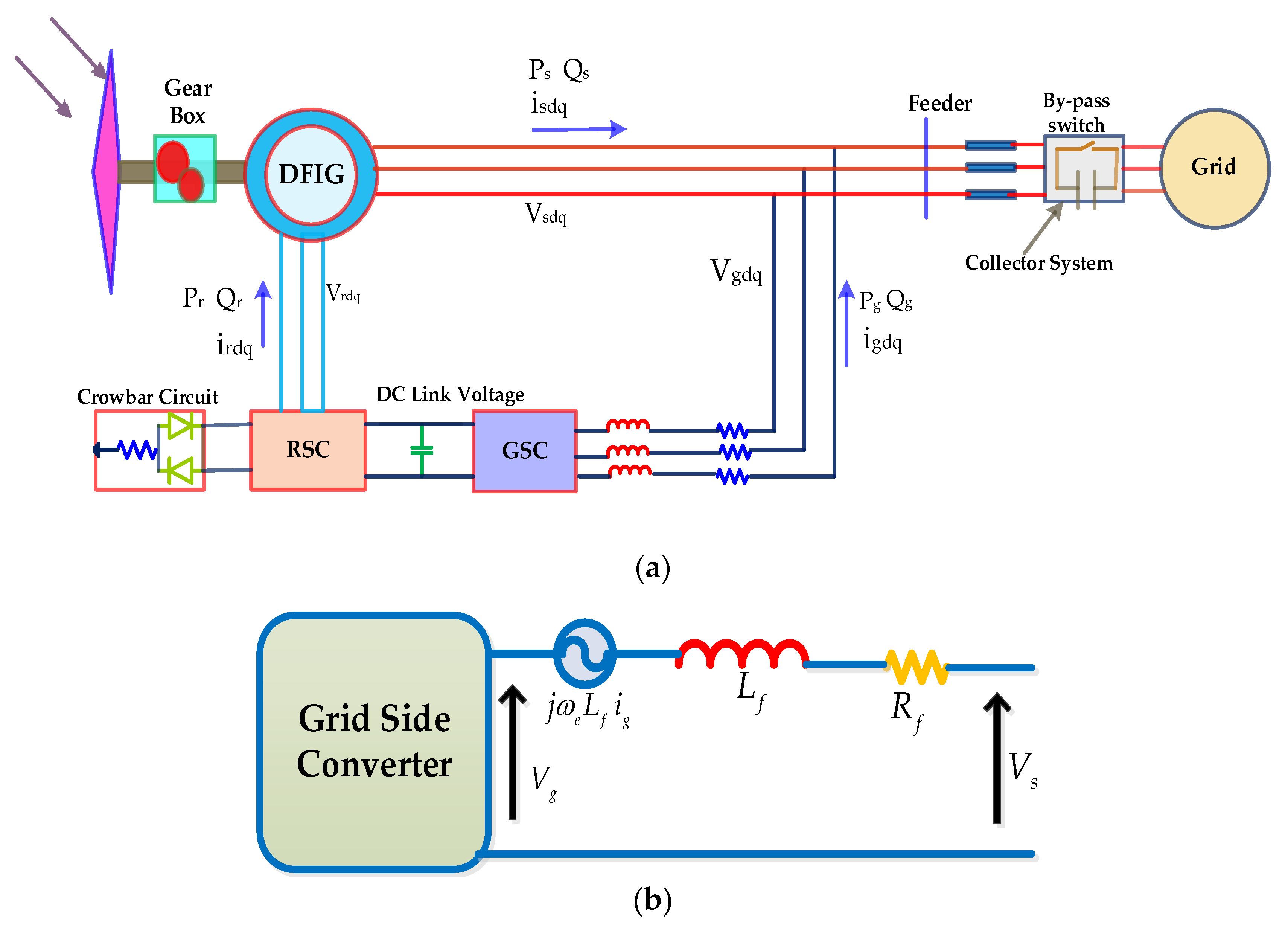
2. Dynamic Model of DFIG WTs in dq Reference Frame

2.1. Dynamic Modeling of DFIG

The dynamic machine model represents the flux, voltage and power that can be expressed as follows:
V s s = R s I s + d λ s d t + j ω e λ s
V r r = R r I r + d λ r d t + j ω s l λ r
λ s = L s I s + L m I r
λ r = L m I s + L r I r
S s = 3 2 V s s I s
S g = 3 2 V s s I g
where R s and R r represent the resistances across stator and rotor of the machine respectively, L s and L r represent the inductances, represent the inductances across stator and rotor of the machine, respectively, while L m represents mutual inductance and ω e is the synchronous (stator) frequency. Moreover, V s s , I s , λ s , V r r , I r and λ r represents the voltage, current and flux, respectively, S s represents the stator power, S g represents the grid power and “ ” represents the conjugate of I s . Subscripts s and r indicates the stator and rotor variables.
From Equations (5) and (6), we have:
I s = 2 3 ( S s V s s )
I g = 2 3 ( S g V s s )
Moreover, the negative sign in Equation (7) denotes the power flow in the stator as shown in Figure 1. The voltage and torque equations represent the exact dynamic model of the induction machine, and the dynamic model wind turbine (WT) of Figure 1 is developed by substituting in exact model of apparent power.
Solving Equations (3) and (4), the rotor current and flux can be described as:
I r = λ s L s I s L m ,   λ r = L r L m ( λ s L s I s )
Equations of stator currents are derived by putting Equations (9) and (4) into Equation (2) and by solving Equations (1) and (2) for I s d and I s q ; thus, the following equations can be achieved:
d I d s d t = a d 1 V d s s a q 1 V q s s + a d 2 λ d s a q 2 λ q s + a d 3 I d s + a q 3 I q s + a d 4 V d r r a q 4 V q r r
d I q s d t = a q 1 V d s s a d 1 V q s s a q 2 λ d s a d 2 λ q s a q 3 I d s a d 3 I q s a q 4 V d r r a d 4 V q r r
where:
a d 1 + j a q 1 = 3 2 ( 1 L s ) , a d 2 + j a q 2 = 3 2 [ ( R r L s L r ) ( ω r L r L s L r ) ] , a d 3 + j a q 3 = j ω s l + ( R s L r L s L r ) + ( R r L s L s L r ) , a d 4 + j a q 4 = 3 2 ( L m L s L r ) .
For λ ˙ s d and λ ˙ s q , stator flux equations can be expressed by substituting I s * in Equation (8) into Equation (1) as:
d λ d s d t = V d s s + b d 1 λ d s + b q 1 λ q s + b d 2 I d s + b q 2 I q s
d λ q s d t = V q s s + b q 1 λ q s + b d 1 λ q s + b q 2 I d s b d 2 I q s
where:
b d 1 + j b q 1 = j ω e ; b d 2 + j b q 2 = 2 3 R s .
The equations for rotor speed and torque WT are specified as follows:
d ω r k d t = p J m ( T e T m )
T e = P I m Ψ s I s
where P , is the no. of pole pairs, J m is the rotor inertia and T m is the mechanical torque.
By inserting Equation (13) into Equation (12), the dynamic model of rotor speed is expressed in terms of stator flux current as follows:
d ω r d t = p 2 J m I m λ s I s p J m T m

2.2. Grid-Side Converterand Filter Model

The grid-side converter with a RL filter is shown in Figure 1b. The dq model of grid-side converter and the filter is provided as follows:
V s s = V g g + L f d i g d t + j ω e L f I g + R f f I g
where V g g represents the grid voltage, I g represents the grid current, L f represents the filter inductance and R f f represents the filter resistance.
The stator voltage can be obtained by substituting Equations (7) and (8) into Equation (15), as follows:
d V s s d t = d V L L d t ( R l + j ω l L l ) { ( 2 S s 3 V s s ) ( 2 S g 3 V s s ) }
The equation of stator voltages can be obtained by substituting Equation (15) into Equation (16), as follows:
d V d s s d t = c d 1 V d s s c q 1 V q s s + c d 2 λ d s c q 2 λ q s + c d 3 I d s + c q 3 I q s + c d 5 V d r r c q 5 V q r r + V ¯ d g g
d V q s s d t = c q 1 V d s s + c d 1 V q s s + c q 2 λ d s + c d 2 λ q s + c q 3 I d s c d 3 I q s + c q 5 V d r r + c d 5 V q r r V ¯ q g g
where:
c d 1 + j c q 1 = ( Z f f L f ) + ( Z L L L s ) + ( Z L L L f ) , c d 2 + j c q 2 = ( R r ω r L r ) ( Z L L L s L r ) , c d 3 + j c q 3 = 2 3 Z L L ( R s l r + R r l s l s l r + j ω s l Z f f l f ) , c d 5 + j c q 5 = ( l m l s l r ) Z L L .
The dynamic model of DFIG is connected to a back-back converter across the DC-link voltage, and it can be obtained at the dc converter node as given below:
V d c ( t ) I d c ( t ) = P g ( t ) P r ( t ) P l o s s ( t )
Here, P r ( t ) , P g ( t ) and P l o s s represents the active, grid and power losses respectively. The switching losses of the converter are neglected due to very small magnitude. S r is defining as follows:
S r = 3 2 V r r I r
By substituting I r from Equation (9) into Equation (19), S r can be obtained as follows:
S ˜ r = 3 2 ( 1 L m λ s ) V r r + ( L s L m I s ) V r r
The DC link voltage model can be obtained by substituting Equation (20) into Equation (18) as follows:
d V d c d t = 1 C V d c { P g Re ( 3 2 L m s λ s + L s L m I s ) V r r }
By solving Equation (16), the following equation can be obtained:
P g = R e { 1 2 Z ˙ L L ( V s s V L L ( V s s ) 2 ) } S s
By substituting Equation (22) into Equation (21), the following equation can be obtained:
d V d c d t = 2 C { 1 2 | Z L L | 2 ( V d L L Z d L L V d s s + V q L L Z q L L V q s s V q L L Z q L L V d s s + V q L L Z q L L V d s s Z d L L ( V d s s ) 2 + Z d L L ( V q s s ) 2 2 ( V d s s V q s s ) k Z q L L ) ( V d s s I d s V q s s I q s ) ( 1.5 1 L m λ d s + L s L m I d s ) V d r r ( 1.5 1 L m Ψ q s L s L m I q s ) V q r r } .
By substituting Equation (11a) and (11b) into Equation (1) and then placing Equation (1) into Equation (5), the following equations can be obtained:
d p s d t = V d s s I q s V q s s I d s E 3 λ d s I q s λ q s I d s + E 4 I 2 d s + E 4 I 2 q s
d q s d t = V d s s I q s + V q s s I d s + E 3 λ d s I d s E 3 λ q s I q s

3. Conventional PI Controller Design

The GSC and RSC controllers are depicted in Figure 2. Active and reactive powers are controlled along the dq-axis rotor currents due to RSC, which provides a self-determining control of a wind turbine (WT). The DC link voltage of the GSC is kept constant for controlling the d-axis current. The grid side current along q-axis is regulated for regulating the exchange of reactive power from the GSC to the grid. The parameters having major influence on the machine operation operates in a steady-state condition to reduce the voltage dip. However, the conventional PI controller increases the efficiency of the machine in order to get maximum power. However, its robustness is often distrusted. Therefore, a robust control system is necessary to certify reference tracking in spite of constraint uncertainties and transients.

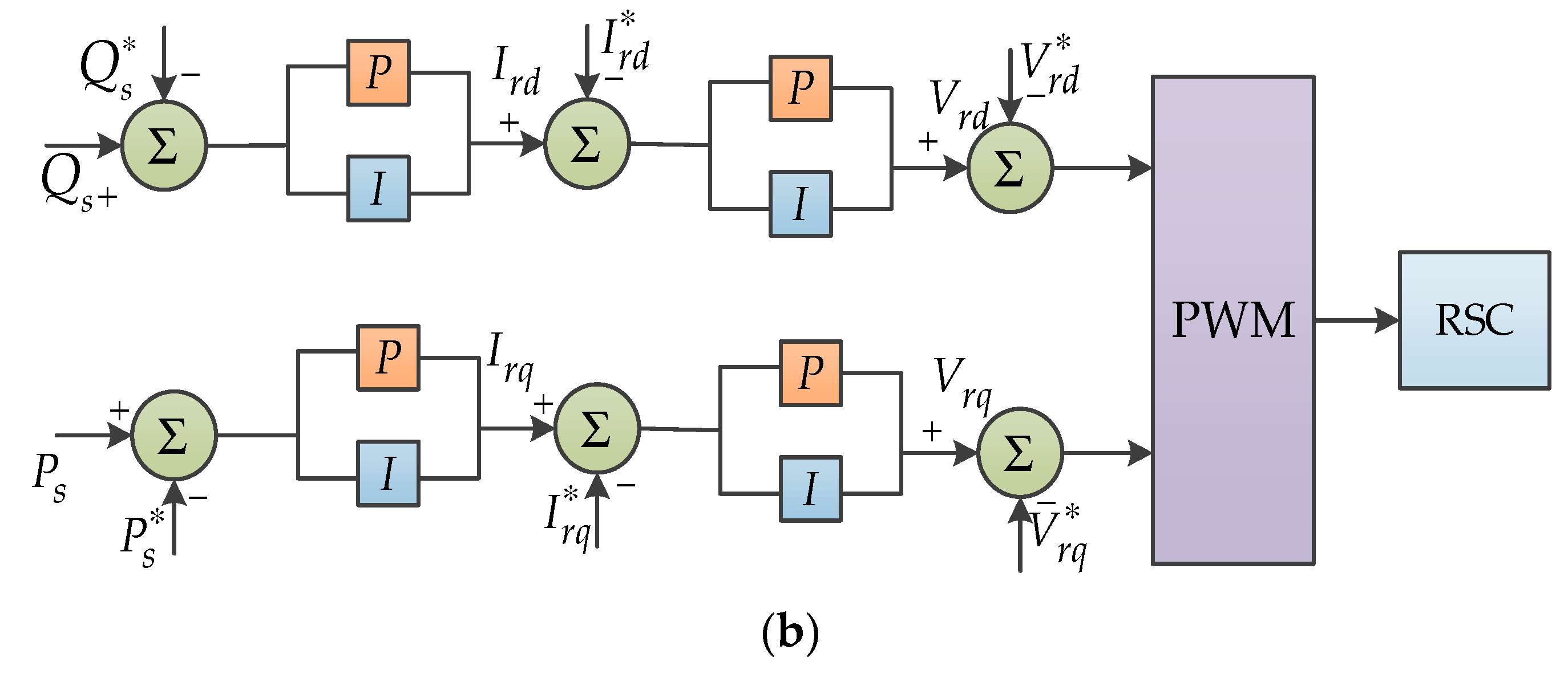
4. Proposed Control Strategy

4.1. Mathematical Modeling of Proposed Control Scheme

In this paper, a state feedback linearization control technique is proposed on a DFIG of 1.5 MW DFIG WT, 575 V base voltage and 50 Hz base frequency. The state feedback linearization control strategy is implemented to convert the nonlinear models into the linear ones by considering their states. This type of control system uses the access to accurate information of existing parameters based on mathematical modeling and handling the variables by considering their dependence on each other that leads to linearization in control system, smooth control signal, robustness against external disturbances and automatic elimination of the requirement for feedforward compensation. When the rotor speed is closer to the synchronous frequency, the system possesses a higher bandwidth for feedback stator flux. Multiple-input and multiple-output (MIMO) system of state feedback linearization control is described in [38,39,40,41,42]. However, the foremost intention of feedback linearization is to transform nonlinear models into linear ones and it is the most authentic approach for handling practical nonlinear control designs.
As the transient stability analysis is dominated by traditional synchronous generators under different constraints, wind turbines use vector control strategy for controlling the stator voltage and current with DFIG. The input parameters of DFIGs are controlled with V d r r , V q r r , V ¯ d q g and V ¯ q g g in a dq reference frame. During normal operating circumstances, the feedback linearization control system is used to reduce the disturbance in a DFIG wind turbine. Feedback linearization control technique substantiates the non-linear dynamic model of the DFIG system. Feedback techniques are considered to reduce the overcurrent for getting finest consequences of the non-linear dynamic model of the DFIG system. The non-linear dynamic model of WT includes RSC and GSC controllers, as depicted in Figure 3. The active power and DC link voltage are the fundamental parameters to control for smooth operation of the system. Therefore, feedback linearization control strategy implemented on an RSC is used to control active power and DC link voltage. However, GSC mitigates the reactive power injected into the grid. In order to execute angular velocity, ω r and fluxes in steady state, it is easier to determine all circumstances; a DC link voltage is applied to maintain the normal operation of the wind turbine in steady state, which indicates that DC link voltage is balanced in the system.
The proposed system variables are defined as follows:
x 6 = [ V d s s V q s s λ d s λ q s I d s I q s ] T
The dynamic model of a DFIG is given in Equations (10a)–(11b) and Equations (17a), (17b) are summarized as follows:
d d t x = A x + B 1 U 1 + B 2 U 2
where:
A = [ c d 1 c q 1 c 2 d c 2 d c 3 d c 3 q c q 1 c d 1 c 2 q c 2 d c 3 q c 3 d 1 0 b 1 d b 1 q b 2 d b 2 q 0 1 b 1 q b 1 d b 2 q b 2 d a 1 d a 1 q a 2 d a 2 q a 3 d a 3 q a 1 q a 1 d a 2 q a 2 d a 3 q a 3 d ] ,   B 1 = [ c 5 d c 5 q c 5 q c 5 d 0 0 0 0 a 4 d a 4 q a 4 q a 4 d ] ,   B 2 = [ 1 0 0 1 0 0 0 0 0 0 0 0 ]
U 1 2 = [ V d r r   V q r r ] T ,   U 2 2 = [ V ¯ d g g   V ¯ q g g ] T
Similarly, the rotor speed and the actual optimal speed are controlled by using feedback linearization control technique to get the current signal along d-axis and compared with the actual axis of the rotor d-axis and q-axis currents. Even if coupling occurs between the d-axis and q-axis voltages, after computation of the d-axis or q-axis rotor voltages, even then a controller can be compensated because the coupling term is relatively smaller as compared to rotor current. It also reduces the oscillations in the system and in control signal. It is obvious that v r and v g are used as the input voltage signals in the feedback linearization control. It is also effective in removing the disturbances and recovering the grid fault.
The oscillations in the stator current are minimized during network perturbations, which improve the capability of the DFIG. The conventional PI controller is not used as it is found not sufficiently robust to provide considerable enhancement to stabilize the system. It is needed for a robust control system to ensure the reference tracking of parameters’ uncertainties and transients. The proposed state feedback control (SFC)is more robust than the conventional PI control technique in order to track the parameters of the reference signal. It is observed that the peak value of the stator current and DC-link voltage are minimized and the disturbance of the system has been cleared.
The following enhanced model is obtained from Equations (14) and (23)–(25):
d ω r d t = x T C ˜ x + C ˜ o
d V d c 2 d t = x T H 1 x + H 2 x + x T H 3 U 1
d p s d t = x H 3 x T
d q s d t = x H 4 x T
where:
C ˜ = [ 0 0 0 0 0 0 0 0 0 0 0 0 0 0 0 0 0 0 0 0 0 0 0 0 0 0 0 p 2 J m 0 0 0 0 p 2 J m 0 0 0 ] T , H 1 = [ m n 0 0 0 0 n m 0 0 0 0 0 0 0 0 0 0 0 0 0 0 0 0 w 3 0 0 0 0 0 0 w 3 0 0 0 0 ] T H 4 = [ 0 0 0 0 0 0 0 0 0 0 0 0 0 0 0 0 0 0 0 0 0 0 0 0 1 0 0 E 3 E 4 0 0 1 E 3 0 0 E 4 ] T , H 5 = [ 0 0 0 0 0 1 0 0 0 0 1 0 0 0 0 0 0 0 0 0 0 0 0 0 0 0 E 3 0 0 0 0 0 0 E 3 0 0 ] T
C ˜ 0 = [ p T m J 0 0 0 0 0 ] T ,   H 3 = [ 0 0 E 1 0 E 1 0 0 0 0 E 2 0 E 2 ] T , H 2 = [ w 1 w 2 0 0 0 0 ] .
where:
m = 1 C ( Z d L L | Z L L | 2 ) , n = 1 C ( Z q L L | Z L L | 2 ) ; E 1 = 1.5 ( 1 L m ) , E 2 = 2 ( L s C L m ) , E 3 = 2 ω e , E 4 = 1.2 R s ; w 1 = { Z d L L V d L L C | Z L L | 2 Z q L L V q L L C | Z L L | 2 } , w 2 = { Z d L L V q L L C | Z L L | 2 Z q L L V q L L C | Z L L | 2 } , w 3 = 2 C ; l s = ( 1 L 2 m L s L r ) L s .
In the given system, the feedback loop is connected to a DFIG and this feedback control has been designed to control the stator current, since RSC of DFIG is employed to adjust the parameters of the controller. The DFIG wind generator phenomena can be attributed between the compensation network and power electronic converter. Stator fault current phase A is measured as shown in Figure 4a,b. An accumulation of stator current oscillations is noticed. The proposed model is verified by designing a conventional model and using it as a standard model. The proposed model is authenticated by using simulation as depicted in Figure 4c.
Voltage root-mean square (RMS) value and stator fault current are compared as depicted in Figure 4d. SFC affects the magnitude of fault current significantly; once again it is confirmed that such complex behavior of a fault current cannot be determined or can be determined inaccurately by the models having the capability of only determining the fundamental frequency components.

4.2. Short Circuit Current Behavior

Induction generator response in case of three-phase permanent faults is shown in Figure 5a,b. In this case, the breaker is tripped when the crowbar is triggered. A spike in the crowbar current shows that the threshold limit is reached because of DC-link voltages. RSC is blocked and does not operate during the interim when crowbar resistance is connected to the rotor. In the meantime, the crowbar is deactivated, restarted and reconnected to the rotor if the DC voltage drops to a lower threshold limit. The saturation occurs in transformer and the unit breaker trips if terminal voltages drop down to the LVRT curve. Figure 5c shows the transformer saturation effect during three-phase permanent faults at the point of common coupling (PCC). A comparison is depicted in the Figure 5c, which shows the results with and without the effect of transformer saturation between the terminal voltages.

4.3. Crowbar Protection

In order to construct a crowbar triggering circuit, a thyristor is used that can be triggered by a gate signal. The circuit will remain in the conduction mode until crowbar current is extinguished [28,29,43,44,45]. On the other side, IGBTs are used in the construction of an active crowbar triggering circuit. It will be turned off if the gate-emitter voltage drops to the threshold value. Both schemes are different; however, excessive rotor current is passing through a resistor in both cases. For crowbar activation, different measures can be used like dc bus voltage or rotor current. It is important that value of the bypass resistor should not be critical but it should be low in order to avoid the large voltage on converter terminals [46]. Therefore, the value of the bypass resistor should be adjusted to acquire the aforementioned characteristics [47]. Passive crowbar configuration is shown in Figure 1a, whereas the difference of operation between two schemes for activation and deactivation of the crowbar circuit during and after the fault is shown in Figure 5d. When a fault occurs in DFIG, LVRT reconnects with back to back converter for controlling the stator current and voltage characteristics used in LVRT system, which is shown in Figure 5c. The short circuit performance of the DFIG wind generator was affected because of the different types of crowbar circuit and LVRT-based on the protection strategy that is considered for the modeling. Instead of a rotor crowbar circuit, a chopper resistance is used in some DFIGs in the DC link capacitor.

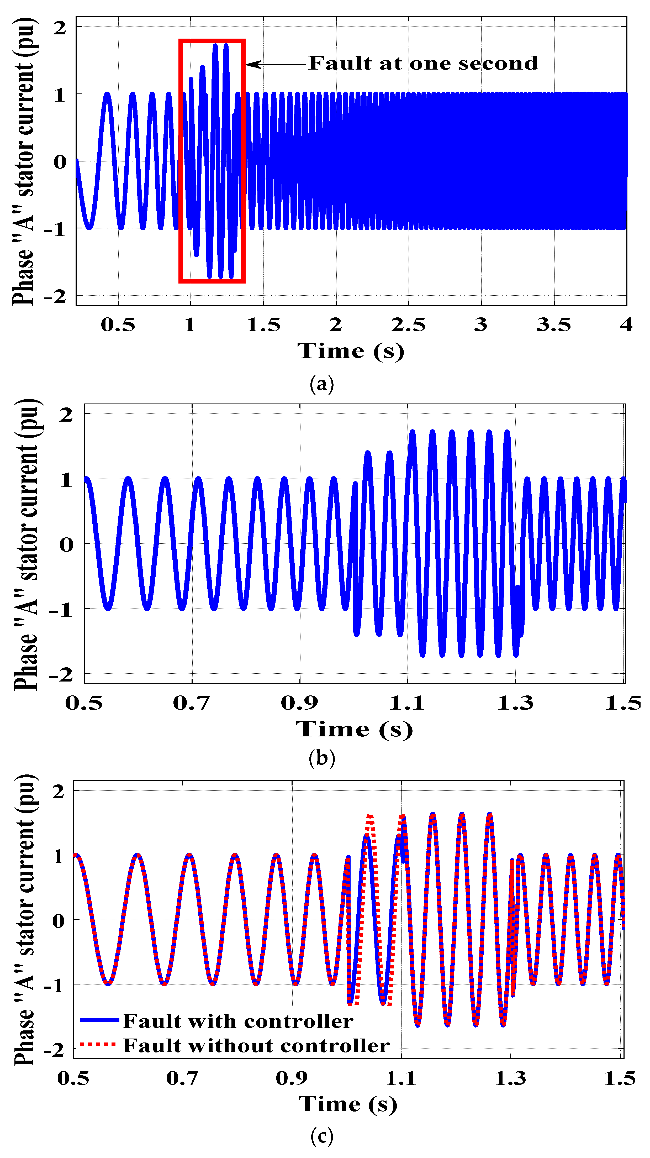
5. Simulations Results

The effectiveness of the proposed controller was validated through MATLAB simulations, where the controller is applied to a 1.5 MW DFIG WT, 575 V base voltage, and 50 Hz base frequency as depicted in Table 1. The proposed model was derived through DFIG wind turbines, and electric power was provided from the generator to meet the different load requirements. In order to validate the performance of the proposed scheme, it was compared with the conventional PI controller by implementing it over the same model.
It was obvious that the mechanical dynamics of a DFIG were adequate enough to remove the disturbance from the machine and stabilize the specified parameters in the machine, such as stator current, stator voltage, active power and reactive power. If the speed of the generator becomes higher than the threshold constriction, the generator may become unstable as the rotor converter cannot handle the slip power. The performance of two control techniques was compared during a fault condition. The SFC technique was used in the first case for reducing the oscillations in stator flux proposed for rotor side converter. However, the DC link voltage was controlled by the grid side converter as depicted in Section 4.2. In the second case, the proposed LVRT approaches were examined for its ride through capability and its efficiency was compared with a conventional PI control without crowbar protection and LVRT approaches. DFIG and grid parameters used in the simulation are listed in Table 1. There were two categories of transient response in DFIG as shown in Figure 6.
Moroever, whenever a fault occurs in the system, the fault clearance time was approximately one second. It is obvious that the proposed control improves the capability of DFIG as compared to the conventional PI controllers, the maximum values of stator voltage, stator flux, stator current and DC link voltage were decreased. The proposed controller had reduced values of DC link voltage and damped the transient behavior of DFIG well. The RSC was designed by feedback linearization method that controlled the fault and made the system stable. Maximum power was generated from DFIG through the wind turbine. An additional part of the RSC enhanced the reactive power that creates the disturbance. The nonlinear dynamic model of the DFIG wind turbine improved the transient response of the grid because of the assistance of the state feedback linearization controller. The dynamic response is depicted in Figure 6. The dynamic response of the stator voltage in dq reference frame and the stator voltage was examined by the decay of 1.5 pu at 1.2 s to recover the stator voltage as depicted in Figure 6 a,b. The response of wind turbine system was improved by the recovery of the fault as fault current was reduced by generating a new component (stator current) I s in dq reference frames as shown in Figure 6c,d. Whereas, Figure 6e,f show the dynamic response of the stator flux and very small deviation generated in the stator flux after 2.5 s in which feedback linearization control techniques recover the symmetrical fault of the stator flux. For a 200 ms three-phase fault at the point of interconnection of a series-compensated DFIG wind farm to the grid, Figure 6g depicts the comparative magnitudes of feedback linearization component dynamic phasors of stator current and the positive sequence. It is observed that disturbance is stable at 1.2 s. The rotor speed of the DFIG is discussed in Equation (15), which can be controlled at 0.15 pu shown in Figure 6h. Real power response at 0.75 pu and reactive power response at 0.62 pu is shown in Figure 6i. Implementation of the proposed method for nonlinear dynamic model validates the efficiency by simulation results. Originally, the performance of DFIG is verified by the nonlinear dynamic system with slight changes in the real power. The dynamic system was verified with a small step change in real power from 0.35 pu to 0.75 pu and at the same time, reactive power was set at zero (pu). The settling time of the active and reactive powers was much less, without overshoot of the zero steady-state faults, as depicted in Figure 6j. The reference signal perfectly tracked the estimated method for the real and reactive power, as shown in Figure 6i,j. The conventional model was compared with the proposed model [29], and it was observed that fault was removed when stator current rises and DC link voltage dropped. During short circuit, fault condition did not include the negative sequence component, because this was an unsymmetrical fault. Furthermore, the zero sequence was not incorporated because the transformer was not grounded. The short circuit current waveform shows the dynamic pharos. The positive sequence was capable of exactly representing the performance of the DFIG wind turbine in symmetrical fault conditions.

6. Conclusions

This paper dealt with the improvement in LVRT capability of DFIGs. The LVRT requirements of DFIGs can be achieved firstly by restraining the exceeded stator current fluctuation in DC link voltage. In order to increase the gear lifetime and machine reliability, it is compulsory to reducethe fluctuations in transient response of DFIG during the voltage dip. In this study, the non-linear dynamic model is proposed that allows the design and calculations regarding fault current and during symmetrical fault condition, the proposed control technique is used to improve the LVRT capability of the DFIG.
However, the method for calculating the SCC was inadequately subsidized by the DFIG. In case of any SCC fault in power system, wind power is restricted and settling time is controlled by the controller for appropriate detection of a fault. Therefore, SCC of DFIG operation under excitation control was emphasized in this paper. As compared to the conventional PI control strategy, the proposed controller reduces the fluctuations in DC-link voltage and improves the effects. As a result of the implementation of the state feedback linearization control technique on both the rotor side as well as on grid side, converters and LVRT capability of DFIG wind turbine gets improved. The proposed scheme enables the DFIG to produce electricity and control signals during fault conditions by absorbing extreme energy and to boost the speed of the rotor in a DFIG.

Author Contributions

G.S.K., D.I. and M.H.B. developed the idea and supervise the project and executed the simulation, S.T.C., M.H.B. and A.A.M. supervised the project. D.M.S. and M.K. helped during the revised version in responding to the editor/reviewers’ comments. D.M.S., M.H.B. and S.T.C. helped in writing and proofreading the manuscript. All authors participated equally.

Funding

This paper is supported by Pusat Pengurusan Penyelidikan (RMC), Universiti Tun Hussein Onn Malaysia, Malaysia.

Acknowledgments

This work was greatly acknowledged by Shanghai Jiao Tong University China, Quaid-e-awam University of Engineering and Technology, Mehran University of Engineering and Technology, University Tunn Hussein Onn Malaysia, Univerisiti Sains Malaysia and COMSATS University Islamabad for means and support.

Conflicts of Interest

Authors declare no conflicts of interest.

References

  1. Hussain Baloch, M.; Ishak, D.; Tahir Chaudary, S.; Ali, B.; Asghar Memon, A.; Ahmed Jumani, T. Wind Power Integration: An Experimental Investigation for Powering Local Communities. Energies 2019, 12, 621. [Google Scholar] [CrossRef]
  2. Baloch, M.H.; Wang, J.; Kaloi, G.S.; Memon, A.A.; Larik, A.S.; Sharma, P. Techno-Economic Analysis of Power Generation from a Potential Wind Corridor of Pakistan: An Overview. Environ. Prog. Sustain. Energy 2019, 38, 706–720. [Google Scholar] [CrossRef]
  3. Baloch, M.H.; Chauhdary, S.T.; Ishak, D.; Kaloi, G.S.; Nadeem, M.H.; Wattoo, W.A.; Younas, T.; Hamid, H.T. Hybrid Energy Sources Status of Pakistan: An Optimal Technical Proposal to Solve the Power Crises Issues. Energy Strategy Rev. 2019, 24, 132–153. [Google Scholar] [CrossRef]
  4. Baloch, M.; Abro, S.; Sarwar Kaloi, G.; Mirjat, N.; Tahir, S.; Nadeem, M.; Gul, M.; Memon, Z.; Kumar, M. A Research on Electricity Generation from Wind Corridors of Pakistan (Two Provinces): A Technical Proposal for Remote Zones. Sustainability 2017, 9, 1611. [Google Scholar] [CrossRef]
  5. Ko, H.S.; Yoon, G.G.; Kyung, N.H.; Hong, W.P. Modeling and control of DFIG-based variable-speed wind-turbine. Electr. Power Syst. Res. 2008, 78, 1841–1849. [Google Scholar] [CrossRef]
  6. Wang, S.; Chen, N.; Yu, D.; Foley, A.; Zhu, L.; Li, K.; Yu, J. Flexible fault ride through strategy for wind farm clusters in power systems with high wind power penetration. Energy Convers. Manag. 2008, 93, 239–248. [Google Scholar] [CrossRef]
  7. Qiao, W.; Zhou, W.; Aller, J.M.; Harley, R.G. Wind speed estimation based sensorless output maximization control for a wind turbine driving a DFIG. IEEE Trans. Power Electron. 2008, 23, 1156–1169. [Google Scholar] [CrossRef]
  8. Huang, X.-b.; Lin, D.; Wang, H.-f.; Lu, N. Low voltage ride through strategy with reactive current injection for grid connected photovoltaic system. J. Mech. Electr. Eng. 2016, 33, 458–463. [Google Scholar]
  9. Ouyang, J.; Xiong, X. Research on the short-circuit current of doubly fed induction generator under non-deep voltage drop. Electr. Power Syst. Res. 2014, 107, 158–166. [Google Scholar] [CrossRef]
  10. Tang, Y.; He, H.; Ni, Z.; Wen, J.; Sui, X. Reactive power control of grid-connected wind farm based on adaptive dynamic programming. Neurocomputing 2014, 125, 125–133. [Google Scholar] [CrossRef]
  11. Li, S. Reliability models for DFIGs considering topology change under different control strategies and components data change under adverse operation environments. Renew. Energy 2013, 57, 144–150. [Google Scholar] [CrossRef]
  12. Song, Y.; Nian, H. Modularized control strategy and performance analysis of DFIG system under unbalanced and harmonic grid voltage. IEEE Trans. Power Electron. 2015, 30, 4831–4842. [Google Scholar] [CrossRef]
  13. Nasr-Azadani, E.; Canizares, C.; Olivares, D.E.; Bhattacharya, K. Stability Analysis of Unbalanced Distribution Systems With Synchronous Machine and DFIG Based Distributed Generators. IEEE Trans. Smart Grid 2014, 5, 2326–2338. [Google Scholar] [CrossRef] [Green Version]
  14. Tahir, S.; Wang, J.; Baloch, M.; Kaloi, G. Digital Control Techniques Based on Voltage Source Inverters in Renewable Energy Applications: A Review. Electronics 2018, 7, 18. [Google Scholar] [CrossRef]
  15. Tahir, S.; Wang, J.; Kaloi, G.S.; Baloch, M.H. Robust digital deadbeat control design technique for 3 phase VSI with disturbance observer. IEICE Electron. Express 2017, 14, 20170351. [Google Scholar] [CrossRef]
  16. Rahimi, M.; Parniani, M. Low voltage ride-through capability improvement of DFIG-based wind turbines under unbalanced voltage dips. Int. J. Electr. Power Energy Syst. 2014, 60, 82–95. [Google Scholar] [CrossRef]
  17. Liu, M.; Pan, W.; Quan, R.; Li, H.; Liu, T.; Yang, G. A Short-Circuit Calculation Method for DFIG-Based Wind Farms. IEEE Access 2018, 6, 52793–52800. [Google Scholar] [CrossRef]
  18. Morren, J.; de Haan, S.W. Short-circuit current of wind turbines with doubly fed induction generator. IEEE Trans. Energy Convers. 2007, 22, 174–180. [Google Scholar] [CrossRef]
  19. Fathabadi, H. Control of a DFIG-based wind energy conversion system operating under harmonically distorted unbalanced grid voltage along with nonsinusoidal rotor injection conditions. Energy Convers. Manag. 2014, 84, 60–72. [Google Scholar] [CrossRef]
  20. Howard, D.F.; Liang, J.; Harley, R.G. Short-Circuit Modeling of DFIGs With Uninterrupted Control. IEEE J. Emerg. Sel. Top. Power Electron. 2014, 2, 47–57. [Google Scholar] [CrossRef]
  21. Yu, S.S.; Zhang, G.; Fernando, T.; Iu, H.H. A DSE-Based SMC Method of Sensorless DFIG Wind Turbines Connected to Power Grids for Energy Extraction and Power Quality Enhancement. IEEE Access 2018, 6, 76596–76605. [Google Scholar] [CrossRef]
  22. Howard, D.F.; Habetler, T.G.; Harley, R.G. Improved sequence network model of wind turbine generators for short-circuiting studies. IEEE Trans. Energy Convers. 2012, 27, 968–977. [Google Scholar] [CrossRef]
  23. Beltran, B.; Ahmed-Ali, T.; Benbouzid, M. High-order sliding-mode control of variable-speed wind turbines. IEEE Trans. Ind. Electron. 2009, 56, 3314–3321. [Google Scholar] [CrossRef]
  24. Erlich, I.; Wrede, H.; Feltes, C. Dynamic behavior of DFIG-based wind turbines during grid faults. IEEJ Trans. Ind. Appl. 2008, 128, 396–401. [Google Scholar] [CrossRef]
  25. Sarasúa, J.I.; Pérez-Díaz, J.I.; Wilhelmi, J.R.; Sánchez-Fernández, J.Á. Dynamic response and governor tuning of a long penstock pumped-storage hydropower plant equipped with a pump-turbine and a doubly fed induction generator. Energy Convers. Manag. 2015, 106, 151–164. [Google Scholar] [CrossRef]
  26. Chandrasekar, S.; Gokaraju, R. Dynamic Phasor Modeling of Type 3 DFIG Wind Generators (Including SSCI Phenomenon) for Short-Circuit Calculations. IEEE Trans. Power Deliv. 2015, 30, 887–897. [Google Scholar] [CrossRef]
  27. Meegahapola, L.; Perera, S. Capability constraints to mitigate voltage fluctuations from DFIG wind farms when delivering ancillary services to the network. Int. J. Electr. Power Energy Syst. 2014, 62, 152–162. [Google Scholar] [CrossRef]
  28. Slotine, J.-J.E.; Li, W. Applied Nonlinear Control; Prentice-Hall: Englewood Cliffs, NJ, USA, 1991. [Google Scholar]
  29. Burgos, R.P.; Wiechmann, E.P.; Holtz, J. Complex state-space modeling and nonlinear control of active front-end converters. IEEE Trans. Ind. Electron. 2005, 52, 363–377. [Google Scholar] [CrossRef]
  30. Mohammadi, J.; Afsharnia, S.; Vaez-Zadeh, S. Efficient fault-ride-through control strategy of DFIG-based wind turbines during the grid faults. Energy Convers. Manag. 2014, 78, 88–95. [Google Scholar] [CrossRef]
  31. Xiao, S.; Yang, G.; Zhou, H.; Geng, H. An LVRT control strategy based on flux linkage tracking for DFIG-based WECS. IEEE Trans. Ind. Electron. 2013, 60, 2820–2832. [Google Scholar] [CrossRef]
  32. Lu, M.; Chen, Y.; Zhang, D.; Su, J.; Kang, Y. Virtual Synchronous Control Based on Control Winding Orientation for Brushless Doubly Fed Induction Generator (BDFIG) Wind Turbines Under Symmetrical Grid Faults. Energies 2019, 12, 319. [Google Scholar] [CrossRef]
  33. Döşoğlu, M.K.; Güvenç, U.; Sönmez, Y.; Yılmaz, C. Enhancement of demagnetization control for low-voltage ride-through capability in DFIG-based wind farm. Electr. Eng. 2018, 100, 491–498. [Google Scholar] [CrossRef]
  34. Justo, J.J.; Mwasilu, F.; Jung, J.W. Doubly-fed induction generator based wind turbines: A comprehensive review of fault ride-through strategies. Renew. Sustain. Energy Rev. 2015, 45, 447–467. [Google Scholar] [CrossRef]
  35. Zhu, R.; Chen, Z.; Tang, Y.; Deng, F.; Wu, X. Dual-loop control strategy for DFIG-based wind turbines under grid voltage disturbances. IEEE Trans. Power Electron. 2016, 31, 2239–2253. [Google Scholar] [CrossRef]
  36. Tohidi, S.; Behnam, M.I. A comprehensive review of low voltage ride through of doubly fed induction wind generators. Renew. Sustain. Energy Rev. 2016, 57, 412–419. [Google Scholar] [CrossRef]
  37. Huang, Q.; Zou, X.; Zhu, D.; Kang, Y. Scaled current tracking control for doubly fed induction generator to ride-through serious grid faults. IEEE Trans. Power Electron. 2015, 31, 2150–2165. [Google Scholar] [CrossRef]
  38. Saad, N.H.; Sattar, A.A.; Mansour, A.E.-A.M. Low voltage ride through of doubly-fed induction generator connected to the grid using sliding mode control strategy. Renew. Energy 2015, 80, 583–594. [Google Scholar] [CrossRef]
  39. Kamel, R.M. Effect of wind generation system types on Micro-Grid (MG) fault performance during both standalone and grid-connected modes. Energy Convers. Manag. 2014, 79, 232–245. [Google Scholar] [CrossRef]
  40. Baloch, M.H.; Wang, J.; Kaloi, G.S. Stability and nonlinear controller analysis of wind energy conversion system with random wind speed. Int. J. Electr. Power Energy Syst. 2016, 79, 75–83. [Google Scholar] [CrossRef]
  41. Kaloi, G.S.; Wang, J.; Baloch, M.H. Dynamic Modeling and Control of DFIG for Wind Energy Conversion System Using Feedback Linearization. J. Electr. Eng. Technol. 2015, 11, 1137–1146. [Google Scholar] [CrossRef]
  42. Kaloi, G.S.; Wang, J.; Baloch, M.H. Active and reactive power control of the doubly fed induction generator based on wind energy conversion system. Energy Rep. 2016, 2, 194–200. [Google Scholar] [CrossRef] [Green Version]
  43. Balogun, A.; Ojo, O.; Okafor, F. Decoupled Direct Control of Natural and Power Variables of Doubly Fed Induction Generator for Extended Wind Speed Range Using Feedback Linearization. IEEE J. Emerg. Sel. Top. Power Electron. 2013, 1, 226–237. [Google Scholar] [CrossRef]
  44. Abdul, H.M.; Mazhar, H.B.; Anwar, A.S.; Amir, M.S.; Zubair, A.M. Achieving High Input Power Factor for Critical Conduction Mode Buck-Buck/Boost Converter. IEEE Access J. 2018, 6, 79082–79093. [Google Scholar]
  45. Memon, A.A.; Shah, S.A.; Shah, W.; Baloch, M.H.; Kaloi, G.S.; Mirjat, N.H. A Flexible Mathematical Model for Dissimilar Operational Modes of a Switched Reluctance Machine. IEEE Access J. 2018, 6, 9643–9649. [Google Scholar] [CrossRef]
  46. Wu, X.; Ning, W.; Yin, T.; Yang, X.; Tang, Z. Robust design method for the SSDC of a DFIG based on the practical small-signal stability region considering multiple uncertainties. IEEE Access 2018, 6, 16696–16703. [Google Scholar] [CrossRef]
  47. Eissa, M. Protection techniques with renewable resources and smart grids—A survey. Renew. Sustain. Energy Rev. 2015, 52, 1645–1667. [Google Scholar] [CrossRef]
Figure 1. (a) Schematic diagram of wind energy doubly fed induction generator (DFIG) system. (b) Equivalent circuit of the grid side converter.
Electronics 08 00777 g001
Figure 2. (a) Conventional proportional-integral (PI) control block diagram of GSC; (b) Conventional PI control block diagram of rotor side converter (RSC).
Electronics 08 00777 g002aElectronics 08 00777 g002b
Figure 3. Over all control diagram and study system of the non-linear dynamic model of the DFIG.
Electronics 08 00777 g003
Figure 4. (a) Symmetrical fault current of the stator; (b) magnified view of the stator fault current controller; (c) stator faults current with and without a controller; (d) comparison of the RMS voltage and current with and without a controller.
Electronics 08 00777 g004aElectronics 08 00777 g004b
Figure 5. (a) Stator current during three-phase fault; (b) stator voltage during three-phase fault; (c) transformer saturation effect on the terminal voltage during a fault; (d) DC link voltage response during fault conditions.
Electronics 08 00777 g005
Figure 6. (a) Stator voltage response; (b) stator voltage phase A response; (c) stator current response; (d) stator current phase A response; (e) stator flux response; (f) stator flux phasor modeling during three-phase symmetrical fault response; (g) positive and negative sequence of the stator for phase A–G response; (h) angular rotor speed response; (i) real power response; (j) reative power response.
Electronics 08 00777 g006aElectronics 08 00777 g006bElectronics 08 00777 g006c
Table 1. 1.5 MW system parameters.
SymbolQuantityValuesSymbolQuantityValues
R s Stator resistance1.4 m Ω R f Grid filter resistance0.04 Ω
R r Rotor resistance0.99 m Ω L f Grid filter inductance0.001 H
L s Stator inductance0.08998 mH F Frequency50 Hz
L r Rotor inductance0.08208 mH V ω Wind speed12 m/s
L m Mutual inductance1.526 mH P Number of pole pairs3
K 1 = [ 0.00589 0.00489 0 0 0 0 0.0888 0.0665 0 0 0 0 ] ,   K 2 = [ 0.0022 0.00315 0.0027 0.00192 0.0012 0.0023 0.0022 0.00315 0.0027 0.0092 0.0012 0.0023 ]

