Article

An Improved Model Predictive Torque Control for a Two-Level Inverter Fed Interior Permanent Magnet Synchronous Motor

1
School of Electrical Engineering and Automation, Tianjin Polytechnic University, Tianjin 300387, China
2
School of Artificial Intelligence, Tianjin Polytechnic University, Tianjin 300387, China
*
Author to whom correspondence should be addressed.
Electronics 2019, 8(7), 769; https://doi.org/10.3390/electronics8070769
Submission received: 21 June 2019 / Revised: 5 July 2019 / Accepted: 8 July 2019 / Published: 10 July 2019
(This article belongs to the Special Issue Industrial Applications of Power Electronics)

Abstract

:
In conventional model predictive control, the dimensions of the control variables are different from each other, which makes adjusting the weighted factors in the cost function complicated. This issue can be solved by adopting the model predictive flux control. However, the performance of the electromagnetic torque is affected by the change of the cost function. A novel model predictive torque control of the interior permanent magnet synchronous motor is presented in this paper, and the cost function involving the excitation torque and reluctance torque is established. Combined with the model predictive flux control and discrete space vector modulation, the current ripple and torque ripple are reduced. The performance of torque under an overload condition is superior to model predictive flux control. The effectiveness of the proposed algorithm is verified by the simulation and experimental results.

1. Introduction

The interior permanent magnet synchronous motor (IPMSM) is widely used in the fields of industry, transportation, and aerospace, because of advantages such as high-power density, high-torque density, and high efficiency [1,2]. Because of the asymmetry rotor magnetic circuit structure, the reluctance torque can be generated by IPMSM. In the traditional control strategy, the d-axis stator current is equal to zero, such that the q-axis current is proportional to the torque required for the PMSMs. However, with the so-called id = 0 control algorithm, the reluctance torque of the IPMSM is not fully employed. Therefore, the maximum torque per ampere control is presented for IPMSM in order to increase the output torque and the efficiency of the motor [3,4].
Traditional control methods of IPMSM mainly include space vector control (SVM) and direct torque control (DTC) [5,6,7]. DTC has advantages of a simple structure, good dynamic performance, and strong robustness, but the torque ripple is high because of adopting the hysteresis controller. An online hysteresis loop adjustment controller is proposed in the literature [8]. It reduces the torque ripple using a proportional-integral (PI) controller to adjust the width of the torque and flux hysteresis loop. Based on duty cycle modulation, other methods combine active vectors with zero vectors to suppress the torque ripple [9,10], but the duty ratio calculation is complex in these methods.
The finite control set model predictive control (FCS-MPC) is adopted to the motor drive system with the development of a digital signal processor (DSP). This method can solve non-linear problems easily [11,12]. The model predictive torque control (MPTC) uses a mathematical model and cost function to replace the torque and flux hysteresis controller and look-up table, compared with the traditional DTC. The optimal switching state is selected from all of the possible switching states in each control period of MPTC. The optimal switching state will be applied in the next control period. Thus, the torque ripple can be reduced, and the output performance of the system will be improved.
The cost function plays a key role in the selection of the optimal switching state [13]. In traditional MPTC, the cost function includes a torque component and stator flux component, which have different units. Weighted factors need to be designed for the two components. The weighted factor is usually determined by the trial-and-error method. Thus, knowing how to avoid the adjusting of the weighted factor has attracted the attention of researchers from all over the world. A multi-objective sorting method is used to eliminate the weighted factor of cost function in the literature [14], which sorts the errors generated by the different switching states from small to large. A new cost function, which is free of a weighted factor, can be established by the sorting results. The authors of [15] use the VIKOR sorting method to eliminate the weighted factor. The authors of [16] built a cost function of the vector duty cycle without a weighted factor. The torque and flux errors in a traditional cost function are replaced by the two deadbeat duty ratios of the adopted vectors. This method solves the problem of duty cycle optimization in traditional MPTC. A model predictive flux control (MPFC) is presented in the literature [17]. Based on the online predictive control of the stator flux vector, the weighted factor is removed from the cost function, and the algorithm is simplified.
In this paper, the torque characteristics of the IPMSM under the MTPA control is analyzed, and an improved MPTC method is proposed based on an IPMSM system driven by a three-phase two-level voltage source inverter. Firstly, instead of the torque and flux components, excitation torque and reluctance torque components are adopted to consist the cost function. As the two torque components share the same unit, the weighted factor is eliminated. Furthermore, the torque ripple under an overload condition is reduced by the adoption of MPFC, and the torque ripple caused by the traditional single vector control is also suppressed by the improved discrete space vector modulation method. Finally, the effectiveness of the proposed method is verified in the whole speed range by the simulation and experimental results.

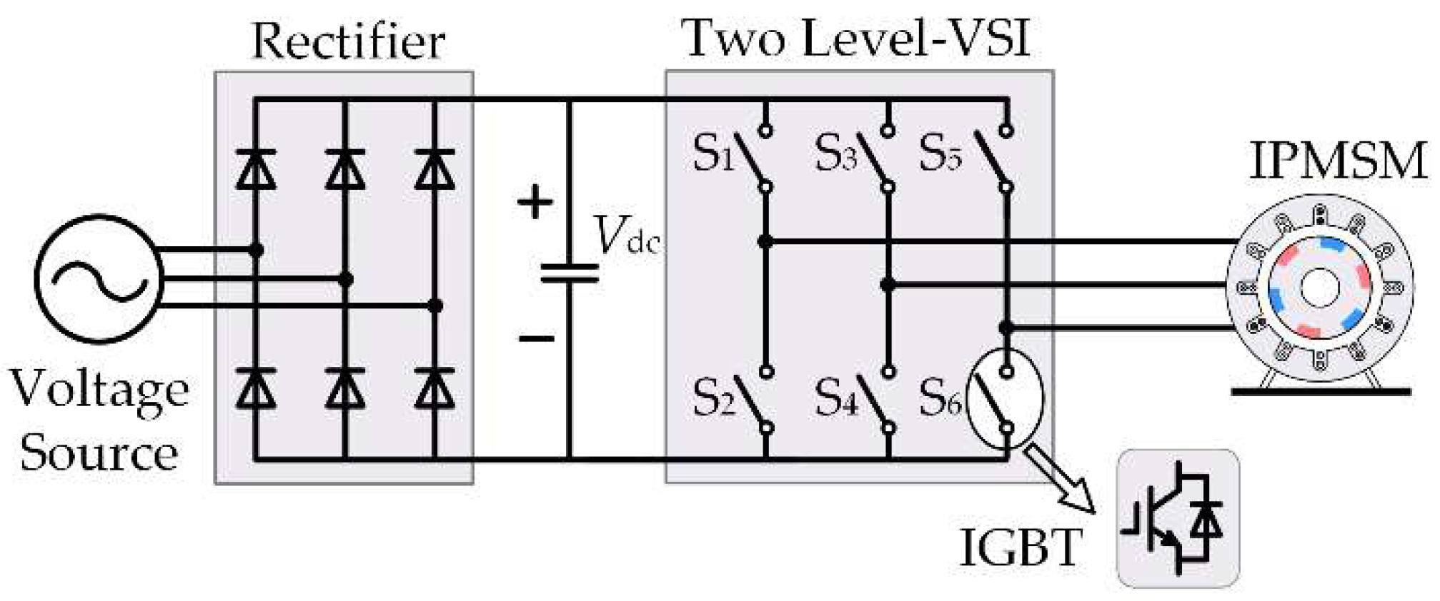
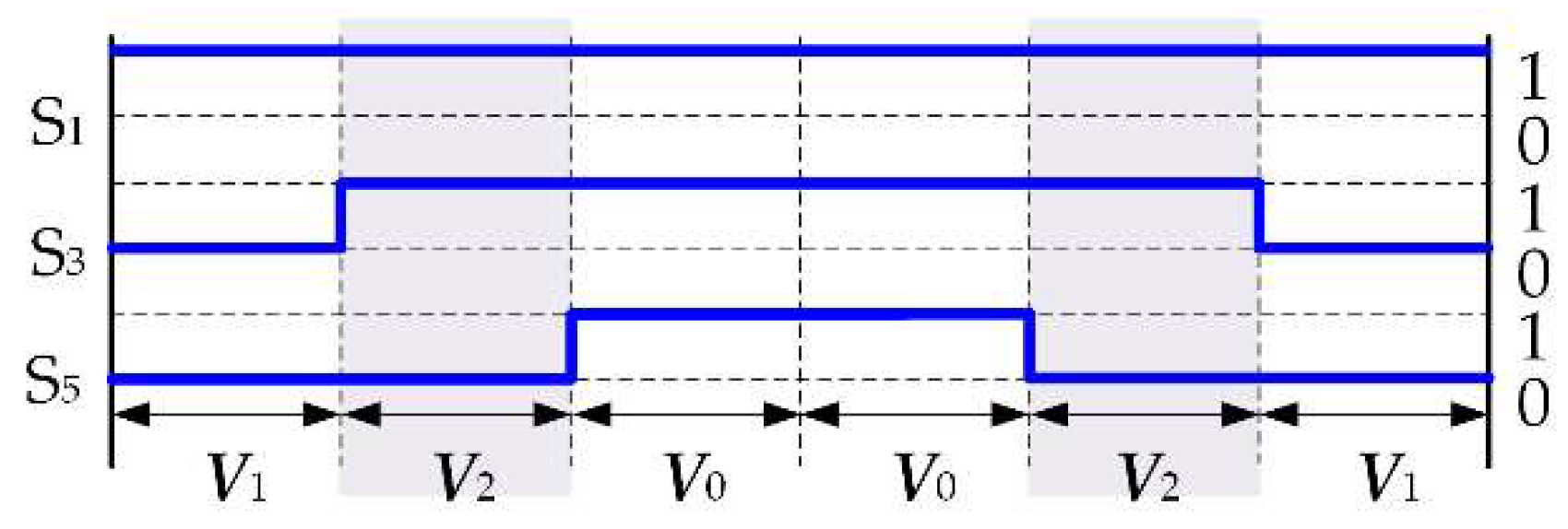
2. The Two-Level Voltage Source Inverters

The topology of a three-phase two-level voltage source inverter (VSI) is shown in Figure 1.
There are 23 = 8 basic voltage vectors in the space diagram, corresponding to eight switching states, including six active basic vectors and two zero basic vectors. The control performance will be affected if one single vector is adopted in each control period. Consequently, if the control period is equally divided into three intervals, two adjacent active vectors and one zero vector are applied in each time interval, and more virtual vectors will be synthesized, as shown in Figure 2. For example, V100 can be synthesized by V1 and V0, which are applied in 1/3 control period and 2/3 control period, respectively, and V112 can be synthesized by V1 and V2, which are applied in a 2/3 control period and 1/3 control period, respectively. If more virtual vectors are applied, the control performance will be improved.

3. Model Predictive Torque Control for IPMSM

3.1. IPMSM Model

The stator voltage equation of the IPMSM in d–q axis rotation coordinate system based on the rotor magnetic field orientation can be expressed as Equation (1).
{ u d = R s i d + L d d i d d t w e L q i q u q = R s i q + L q d i q d t + w e ( ψ f + L q i q ) ,
where, ud and uq represent the d-axis and q-axis components of the stator voltage, respectively; id and iq represent the d-axis and q-axis components of the stator current, respectively; Ld and Lq represent the d-axis and q-axis the stator inductance; Rs represents the stator resistance; ωe is the electrical rotor speed; and ψf is the permanent magnet flux linkage.
The expressions of the electromagnetic torque (Te) and d–q axis stator flux components are as follows:
T e = 3 p 2 [ ψ f i q + ( L d L q ) i d i q ] ,
{ ψ d = L d i d + ψ f ψ q = L q i q ,
where, ψd and ψq represent the d-axis and q-axis components of the stator flux linkage, respectively, and p is the number of pole pairs. As LdLq in IPMSM, the electromagnetic torque can be divided into two components. One is the excitation torque, and the other is the reluctance torque.
For IPMSM, the traditional id = 0 control algorithm is not suitable, because the reluctance torque is not considered. The maximum torque per ampere (MTPA) control is usually adopted. The d-axis and q-axis current are distributed according to Equation (2), so as to realize the maximization of the electromagnetic torque. As shown in Figure 3, the blue solid lines represent the constant torque loci for different values of Te as a function of the d-axis and q-axis current components. So, there must be a certain point in each constant torque locus corresponding to the minimum amplitude of the stator current. The red solid line represents the minimum points for different values of Te, which is usually referred to as the MTPA trajectory.

3.2. Model Predictive Torque Control

The feedback signals of the stator current, position, and speed of the rotor can be obtained by the current sensor and the encoder. Then, combined with the mathematical model of the motor, the impact of each vector on the stator current can be predicted. The relationship is as follows:
{ i d n ( k + 1 ) = i d ( k ) + 1 L d [ w e ( k ) L q i q ( k ) R s i d ( k ) + V d n ] T s i q n ( k + 1 ) = i q ( k ) + 1 L q [ w e ( k ) L d i d ( k ) R s i q ( k ) w e ( k ) ψ f + V q n ] T s ,
where, n = 1, 2, 3… is the number of voltage vectors and its related variables; Ts is the control period; and x(k) and x(k + 1) are the values of variable x at the beginning of the kth and (k + 1)th control period, respectively. The electromagnetic torque (Ten(k + 1)) and the stator flux (ψsn(k + 1)) generated by the voltage vector (Vn) can be obtained by Equations (2) to (4).
The reference value and predictive value of the torque and flux are substituted in Equation (5). The optimal vector can be determined according to the value of the cost function.
{ g ( n ) = | T e * T e n ( k + 1 ) | + Q | ψ s * | ψ s n ( k + 1 ) | | V opt = V argmin g ( n ) ,
where, Vopt is the optimal voltage vector, and Q is the weighted factor, which is the absolute value of the ratio of the rated torque to the rated flux, as shown in Equation (6).
Q = | T N ψ N | .
However, the weighted factor (Q) obtained from Equation (6) cannot be used directly. It needs to be adjusted according to the operation condition. The optimal vector obtained in the kth control period can only be applied in the (k + 1)th control period. Therefore, the cost function can be further improved, as follows:
{ g ( n ) = | T e * T e n ( k + 2 ) | + Q | ψ s * | ψ s n ( k + 2 ) | | V opt = V argmin g ( n ) .
The predictive values of the torque and flux in the (k + 2)th control period in Equation (7) are obtained based on the predictive value of the (k + 1)th period, which could be obtained by Equation (4) and the output voltage vector of the kth period. According to the above principle, the MPTC block diagram is shown in Figure 4.

3.3. Model Predictive Flux Control

The weighted factor will be eliminated in the model predictive flux control (MPFC) [17] if the control object is changed from the torque to the flux. The algorithm is simplified because only the prediction of the stator flux is needed. The implementation of MPFC is as follows.
The reference value (TE*), which is the output of the PI controller in the outer loop, is used as the input of the MTPA algorithm. The outputs of the MTPA algorithm are the d-axis and q-axis components of the reference flux of ψd* and ψq*, respectively. The d-axis and q-axis flux components, ψdn(k + 2) andψqn(k + 2), respectively, with respect to the different voltage vectors, are deduced by substituting all of the voltage vectors in the finite control set into Equations (3) and (4), and then the cost function can be established as follows:
{ g ( n ) = | ψ s * ψ s n ( k + 2 ) | = | ψ d * ψ d n ( k + 2 ) | + | ψ q * ψ q n ( k + 2 ) | V opt = V argmin   g ( n ) .
The control objective of the MPFC is the stator flux, and the weighted factor is eliminated. Although the flux ripple is reduced, the torque ripple is increased. So, the cost function needs to be redesigned in order to improve the torque control performance.

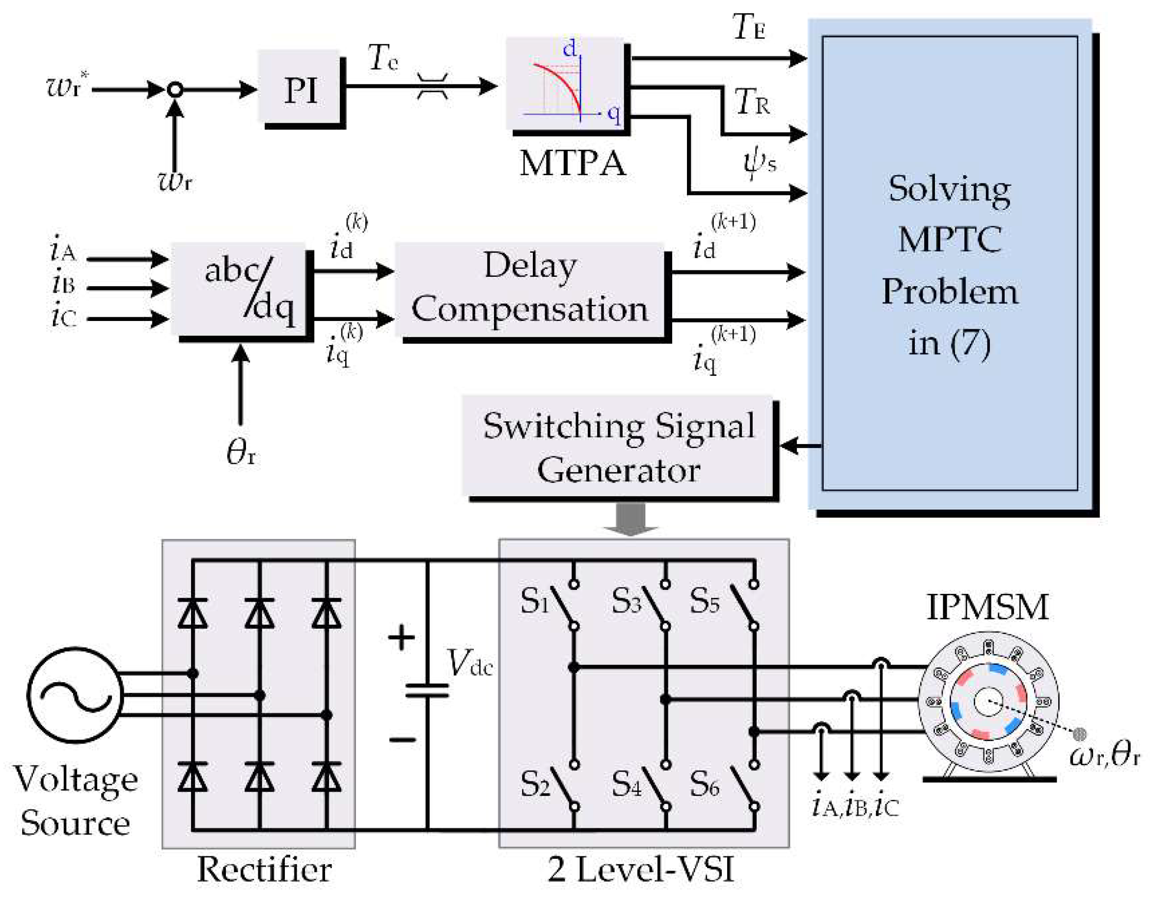
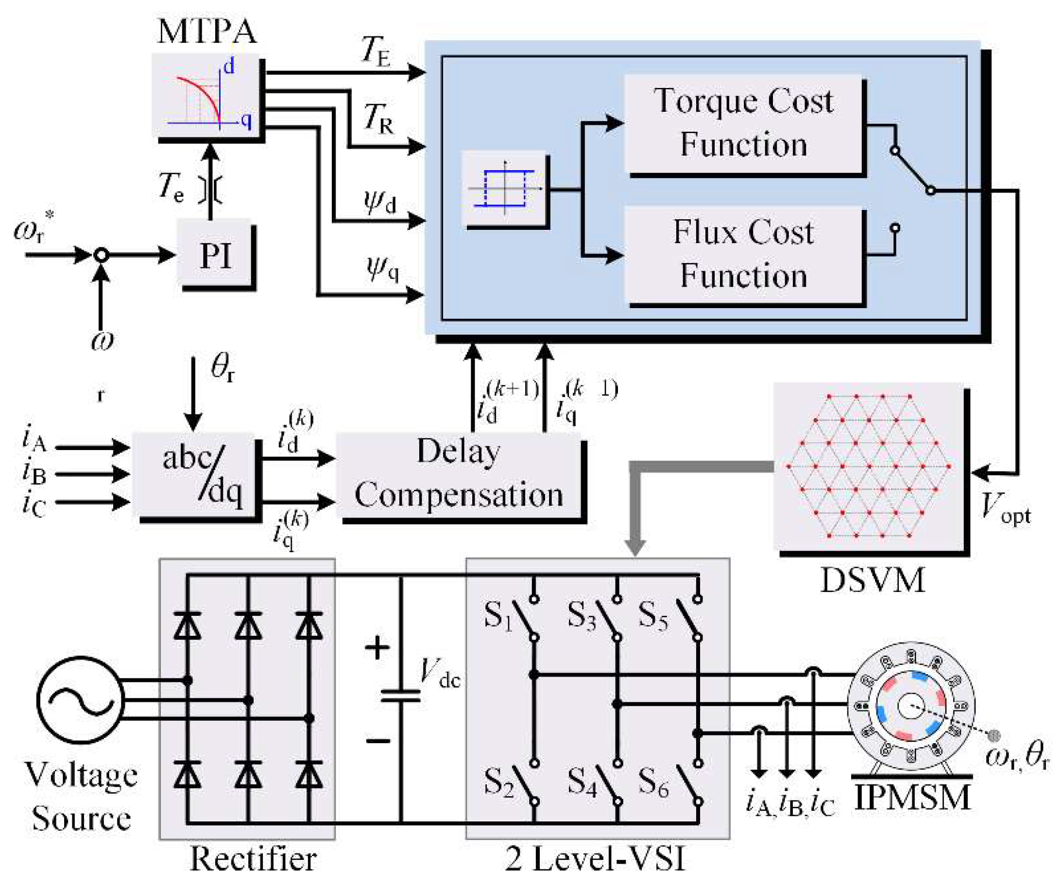
4. Improved Model Predictive Torque Control

The torque control performances of both MPTC and MPFC are limited, because the cost function contains a flux component. However, the current will be unstable if the flux component is abandoned. So, a modified predictive control algorithm is presented in order to improve the torque control performance.

4.1. Improved Cost Function

For IPMSM, the torque can be regarded as the sum of the excitation torque and reluctance torque, and then Equation (2) can be rewritten as follows:
T e = T E + T R ,
where, TE = 3pψfiq/2 is the excitation torque generated by the permanent magnet, which is proportional to the q-axis current; TR = 3p(Ld-Lq)idiq/2 is the reluctance torque generated by the magnetic reluctance, and is proportional to the product of d-axis and q-axis currents.
The d–q axis currents id and iq can be restricted by controlling TE and TR, respectively. Accordingly, the modified cost function can be constructed as follows:
{ g ( n ) = | T E * T E n ( k + 2 ) | + | T R * T R n ( k + 2 ) | V opt = V argmin g ( n ) .
It can be seen from Equation (10) that the units of both the excitation torque and reluctance torque are the same, so the weighted factor is unnecessary. Moreover, the torque control performance is directly influenced by the cost function, and the torque control performance can be improved.
For example, a motor with Ld = 0.200 mH, Lq = 0.555 mH, and ψf = 0.07574 Wb is analyzed. The data of TE and TR are shown in Figure 5. The simulation results of the stator current under a 10% rated load condition are shown in Figure 6.
It can be concluded from Figure 3, Figure 5 and Figure 6 that the MTPA curve approximately coincides with the reference line of id = 0 when the motor is operated in conditions of no load and a light load. The torque is mainly composed of the excitation torque, which results in the fluctuation of the d-axis current. So, the cost function needs to be reconstructed in order to improve the torque performance in conditions of no load and a light load. The new cost function is as follows:
{ g ( n ) = { | ψ d * ψ d n ( k + 2 ) | + | ψ q * ψ q n ( k + 2 ) | | T e * | < T X | T E * T E n ( k + 2 ) | + | T R * T R n ( k + 2 ) | | T e * | > T X V opt = V argmin g ( n ) ,
where, TX is the threshold value of the torque for switching the two cost functions in Equation (11), which is related to the motor’s parameters.
The cost function will be switched frequently when TX is close to the reference torque (Te*), so a hysteresis comparator with a reasonable width is adopted for eliminating unnecessary switches. The proposed method combines the advantages of the traditional MPTC and MPFC. The weighted factor is eliminated, and the torque control performance is improved under a heavy load condition.

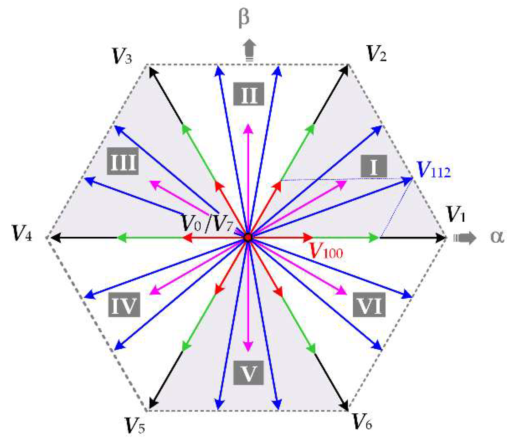
4.2. Finite Control Set

The number of virtual voltage vectors is increased to 40 by using the discrete voltage vector synthesis method, as shown in Figure 2. However, with the increase in virtual voltage vectors, the optimization process is more complicated. So, the three virtual voltage vectors nearest to the reference vector are preselected as the new finite control set. Then, the voltage vector that minimizes the value of the cost function can be obtained, and the switching signals can be generated by the PWM modulator, according to the selected voltage vector [18]. For example, when the optimal voltage vector is V120, the switching signals are as shown in Figure 7.
Compared with the traditional control algorithm, the calculation process is simplified and the performance of the system is improved. The control diagram of the proposed algorithm is illustrated in Figure 8.
It is worth mentioning that the mathematical model and parameters of the motor system are often nonlinear, time-varying, and strongly coupled. The basis of the rigorous optimization method is the parameter precision of the object model. Therefore, the rigorous optimization method often leads to a decrease in the control performance, or even results in control failure.
The model predictive torque control proposed in this paper belongs to the category of model predictive control. Model predictive control generally includes the following three parts: predictive model, rolling optimization, and feedback correction. The predictive model indicates the relationship between the inputs and outputs of the control system. Then, the cost function could be established so as to evaluate the impact of each possible control behavior on a certain control performance in the current control period. The control-behavior minimizing the cost function will be applied to the system in the next control period. Although the control performance may be affected by the accuracy of the predictive model, the rolling optimization could restrain the errors caused by the model mismatch, time-varying, and disturbance, and guarantee a good performance of the control system.

5. Simulation and Experimental Results

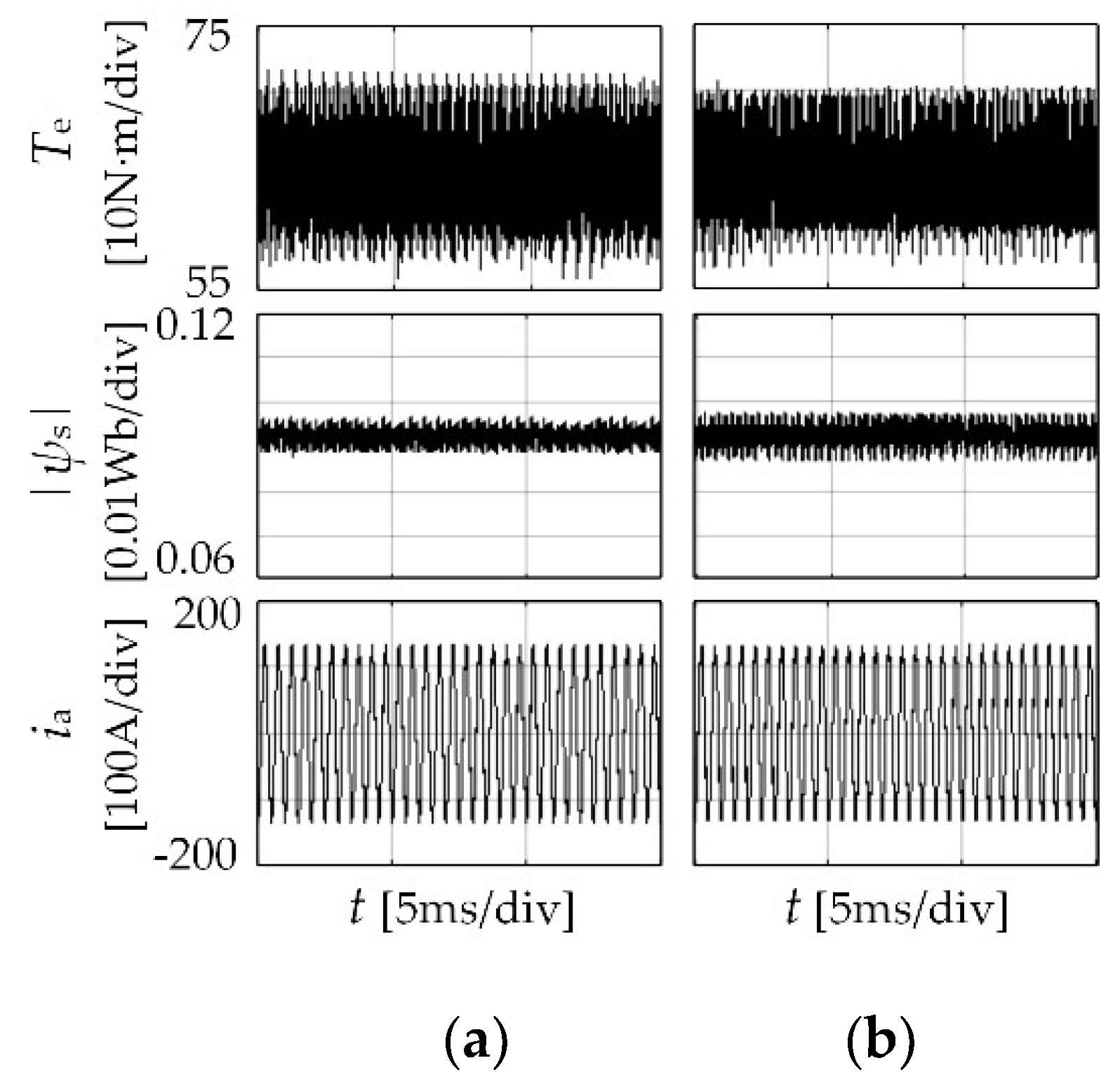
5.1. Simulation Analysis

The traditional and the proposed methods are simulated by MATLAB/Simulink, respectively. The sampling frequency of the single vector algorithm is 20 kHz, and the sampling frequency of the discrete voltage vector algorithm is 10 kHz. TX is 40 N·m. The parameters of the motor are shown in Table 1.
The standard deviation is adopted for evaluating the control performance of different algorithms, which is defined as follows [15]:
{ σ x = 1 n 1 i = 1 n ( x ( i ) x ¯ ) 2 x ¯ = 1 n i = 1 n x ( i ) .
The rotator speed (nr), electromagnetic torque (Te), stator flux amplitude (|ψs|), and stator current (ia) of the traditional and the proposed algorithms are shown in Figure 9. The motor is accelerated from a static state to the rated speed. Figure 9a shows the results of the algorithm of the improved cost function of Equation (11) with a single vector modulation. Figure 9b shows the results of the algorithm of MPFC with discrete voltage vector modulation. Figure 9c shows the results of the proposed algorithm.
From Figure 9a, the speed of the motor is accelerated smoothly from 0 rpm to 3000 rpm (rated speed). Then, the torque reference is stepped up from 0 to 64 N·m (rated load), and the motor reaches the steady state rapidly. This indicates that the system has the ability of anti-disturbance. As can be seen from Figure 9b,c, with the adoption of discrete voltage vector modulation, the stability of the system remains. Moreover, the torque and flux ripples of both the proposed algorithm and MPFC are restrained.
The performances of the proposed algorithm and MPFC under a rated load/different speed conditions, both with discrete voltage vector modulation, are shown in Figure 10 and Figure 11. For these two methods, the standard deviations of the torque are 2.54 and 2.03 N·m at a 10% rated speed, calculated according to Equation (12). While, the standard deviations of the torque are 2.56 and 2.31 N·m at the rated speed, respectively. Thus, the torque ripple of the proposed algorithm is lower than the MPFC under a rated load condition.

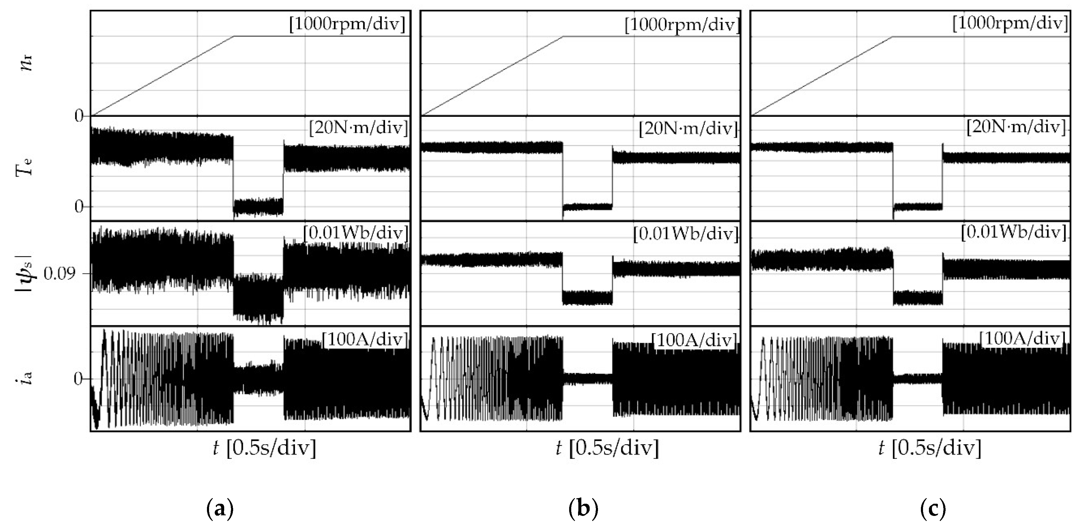
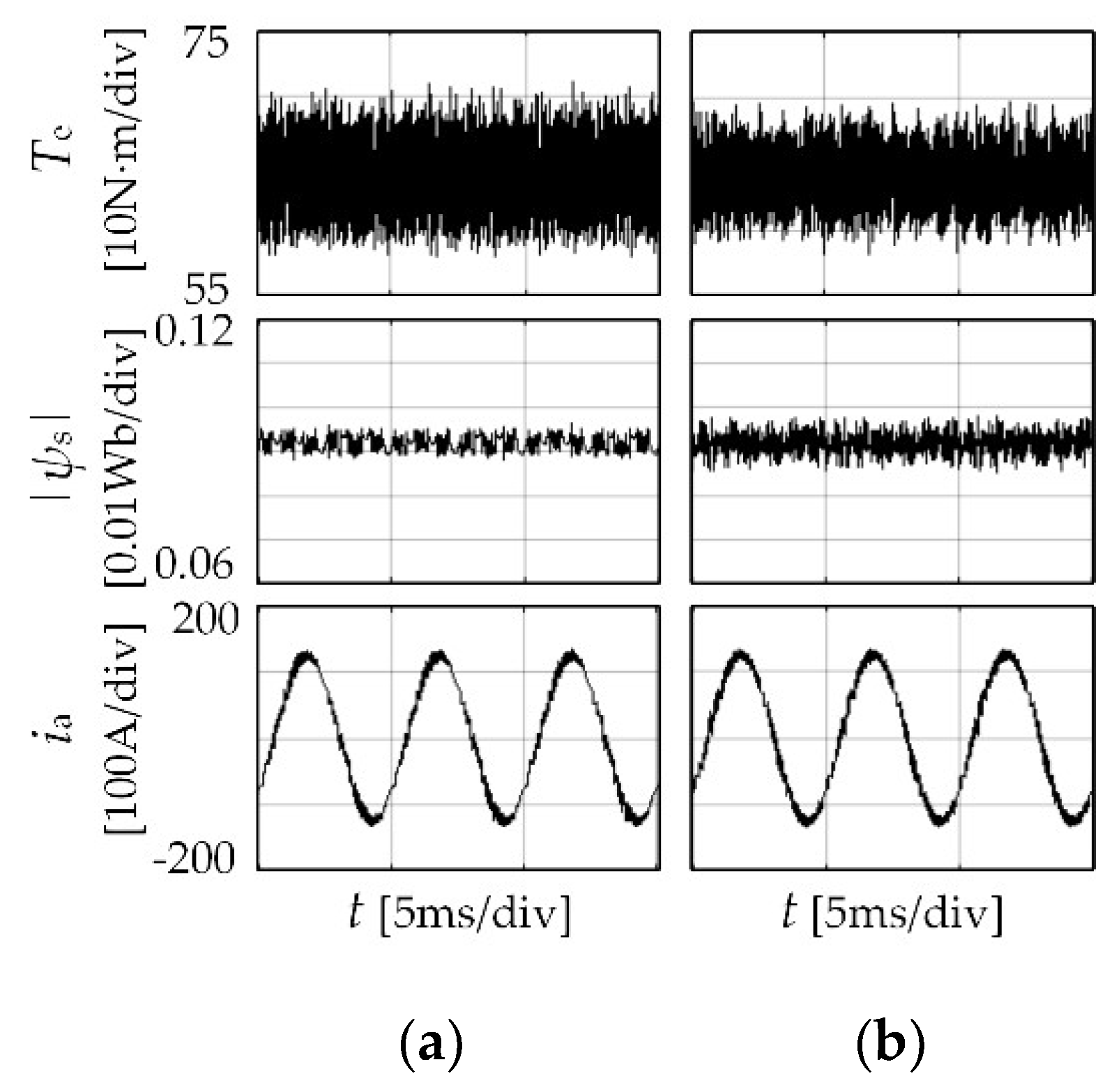
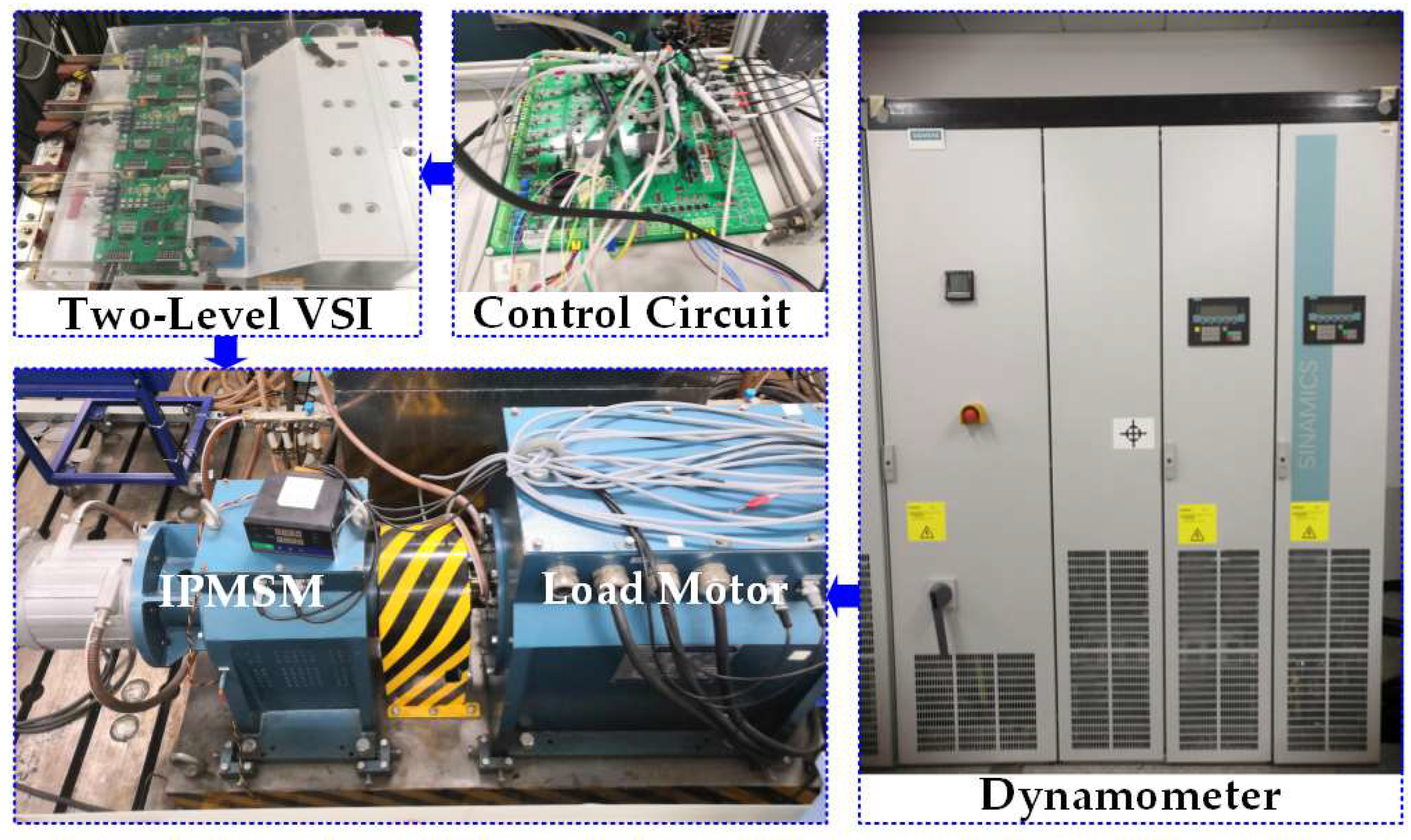
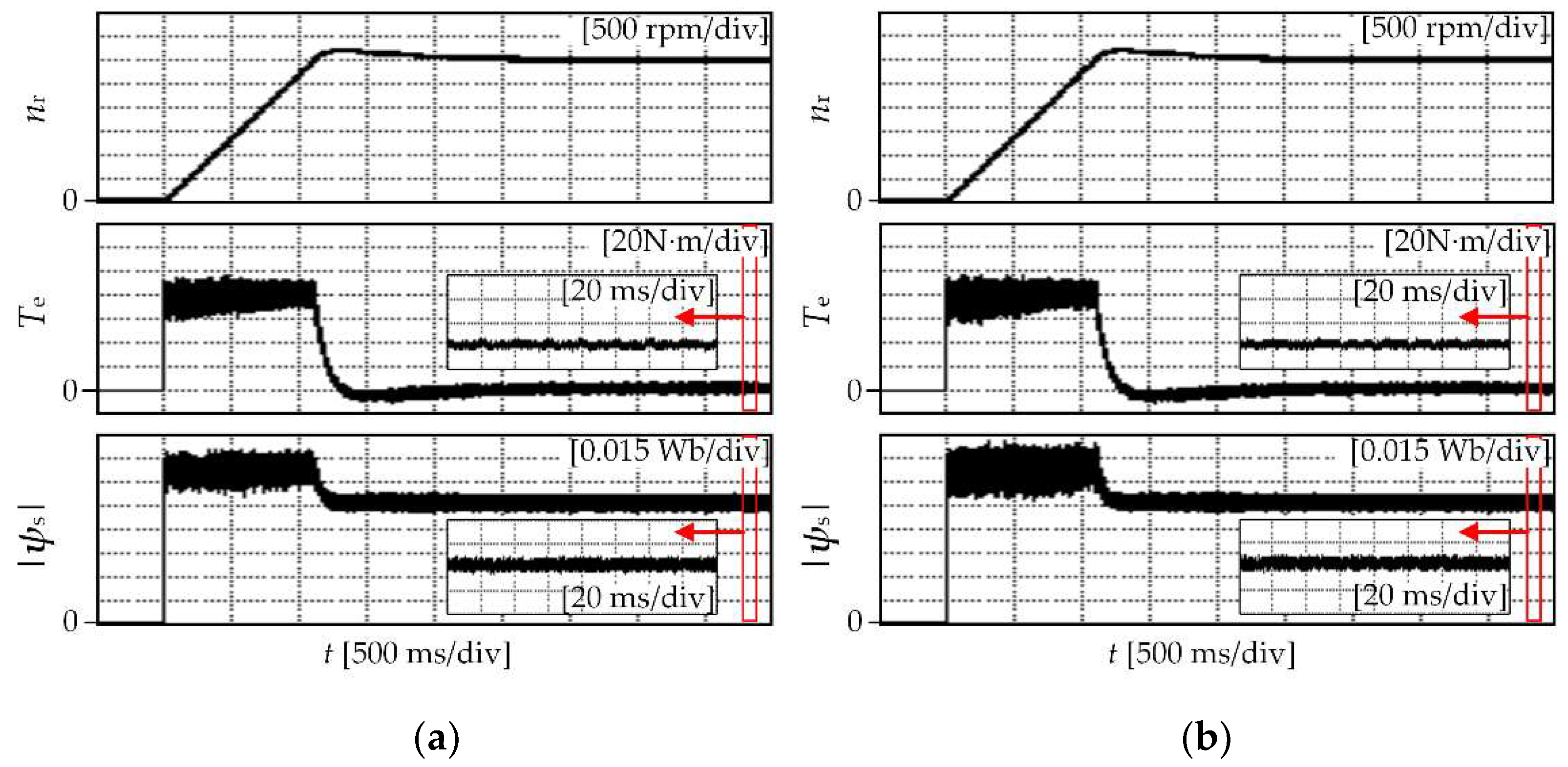
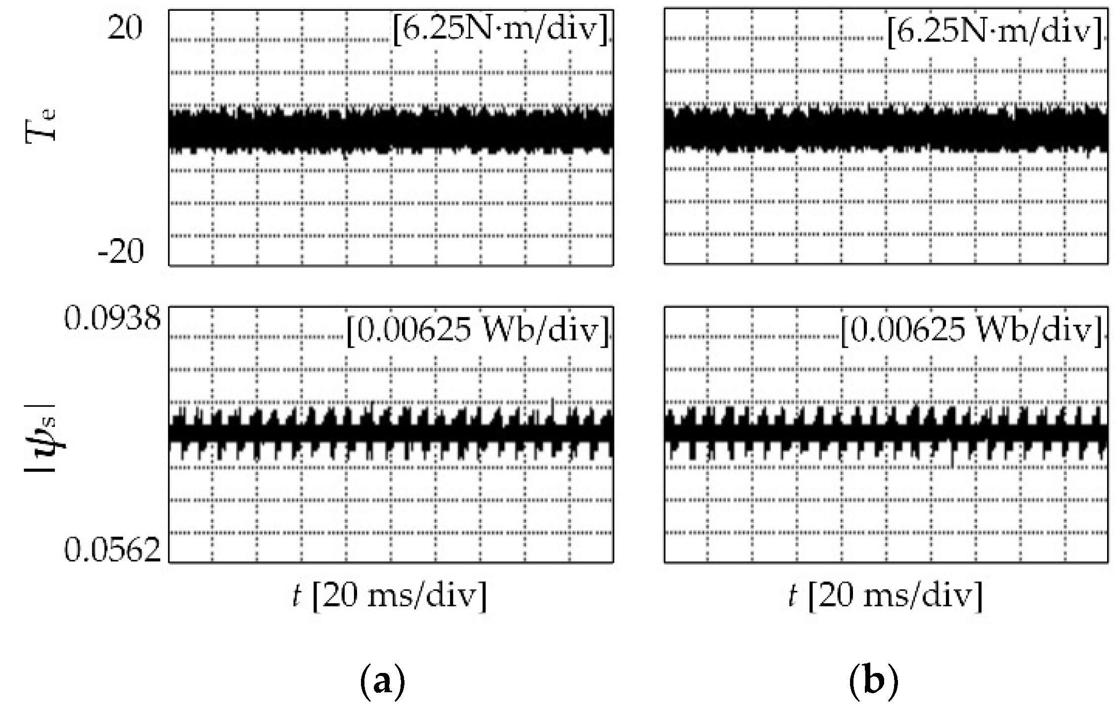
5.2. Experimental Results

The proposed algorithm is implemented and evaluated on a 20-kW IPMSM driven by a two-level inverter, and the digital control unit is based on a Texas Instruments (Dallas, TX, USA) TMS320F28335 digital signal processor (company, city, country), both illustrated in Figure 12. The parameters of the motor are consistent with the simulation.
The speed of the motor is accelerated from 0 to 3000 rpm (rated speed) under a no-load condition. The torque and stator flux waveforms of the MPFC and proposed algorithm, both with a discrete voltage vector, are shown in Figure 13.
As can be seen from Figure 13, for both of the two algorithms, the speed of the motor is accelerated smoothly from 0 to 3000 rpm (rated speed). The torque and flux ripples under a no-load condition are almost the same.
Then, the torque reference is stepped from 0 to 64 N·m (rated load). The torque and stator flux waveforms of the MPFC and proposed algorithm, both with a discrete voltage vector, are shown in Figure 14.
As can be seen, the motor reaches the steady state rapidly. It indicates that the system has the ability of anti-disturbance. Moreover, the torque ripple of the proposed algorithm is lower than that of MPFC.
The performance of the proposed method in the whole speed range is also verified. The speed reference is set to 10% of the rated speed, and the torque and stator flux waveforms at a steady state in conditions of no-load and a rated load are shown in Figure 15 and Figure 16, respectively.
Under a low speed/rated load condition, the torque ripple of the proposed algorithm is lower than MPFC. While, under a low speed/no-load condition, the torque rippled of the proposed algorithm is the same as that of MPFC. The standard deviations of the above experimental results are calculated according to Equation (12), and shown in Table 2. As can be seen, the torque ripple of the proposed algorithm is lower than MPFC under heavy load conditions.

6. Conclusion

An improved MPTC algorithm is presented for IPMSM. The cost function is redesigned according to the load conditions. MPFC is adopted under light load conditions, so that there is no weighted factor in the cost function. While, under heavy load conditions, the weighted factor is eliminated by converting the torque and flux components to excitation torque and reluctance torque components, respectively, and the torque ripple is reduced. The simulation and experimental results verify the effectiveness of the proposed method.

Author Contributions

Conceptualization, X.G., X.L., and G.Z.; methodology, G.Z. and C.C.; software, Z.W.; validation, G.Z. and X.L.; formal analysis, G.Z. and C.C.; writing (original draft preparation), C.C.; writing (review and editing), X.G. and Z.W., and; funding acquisition, G.Z. and X.L.

Funding

This research was funded by the Youth Fund Projects of the National Natural Science Foundation of China, grant numbers 51807140 and 51807141.

Conflicts of Interest

The authors declare no conflict of interest.

References

  1. Yuan, T.; Wang, D. Performance Improvement for PMSM DTC System through Composite Active Vectors Modulation. Electronics 2018, 10, 263. [Google Scholar] [CrossRef]
  2. Kamel, T.; Abdelkader, D.; Said, B.; Padmanaban, S.; Iqbal, A. Extended Kalman Filter Based Sliding Mode Control of Parallel-Connected Two Five-Phase PMSM Drive System. Electronics 2018, 2, 14. [Google Scholar] [CrossRef]
  3. Wang, M.; Hsieh, M.; Lin, H. Operational Improvement of Interior Permanent Magnet Synchronous Motor Using Fuzzy Field-Weakening Control. Electronics 2018, 12, 452. [Google Scholar] [CrossRef]
  4. Bolognani, S.; Peretti, L.; Zigliotto, M. Online MTPA Control Strategy for DTC Synchronous-Reluctance-Motor Drives. IEEE Trans. Power Electron. 2011, 26, 20–28. [Google Scholar] [CrossRef]
  5. Du, M.; Tian, Y.; Wang, W.; Ouyang, Z.; Wei, K. A Novel Finite-Control-Set Model Predictive Directive Torque Control Strategy of Permanent Magnet Synchronous Motor with Extended Output. Electronics 2019, 4, 388. [Google Scholar] [CrossRef]
  6. Kirankumar, B.; Reddy, Y.V.S.; Vijayakumar, M. Multilevel inverter with space vector modulation: Intelligence direct torque control of induction motor. IET Power Electron. 2017, 10, 1129–1137. [Google Scholar] [CrossRef]
  7. Pratibha, N.; Srinivas, S.; Ittamveettil, H. Five-level torque controller-based DTC method for a cascaded three-level inverter fed induction motor drive. IET Power Electron. 2017, 10, 1223–1230. [Google Scholar] [CrossRef]
  8. Zhu, Z.Q.; Ren, Y.; Liu, J. Improved torque regulator to reduce steady-state error of torque response for direct torque control of permanent magnet synchronous machine drives. IET Electr. Power Appl. 2014, 8, 108–116. [Google Scholar] [CrossRef]
  9. Ren, Y.; Zhu, Z.Q.; Liu, J. Direct Torque Control of Permanent-Magnet Synchronous Machine Drives With a Simple Duty Ratio Regulator. IEEE Trans. Ind. Electron. 2014, 61, 5249–5258. [Google Scholar] [CrossRef]
  10. Zhang, Y.; Zhu, J. A Novel Duty Cycle Control Strategy to Reduce Both Torque and Flux Ripples for DTC of Permanent Magnet Synchronous Motor Drives with Switching Frequency Reduction. IEEE Trans. Power Electron. 2011, 26, 3055–3067. [Google Scholar] [CrossRef]
  11. Masoud, A.; Farasat, M.; Jafarishiadeh, S. Model predictive current control of surface-mounted permanent magnet synchronous motor with low torque and current ripple. IET Power Electron. 2017, 10, 1120–1128. [Google Scholar] [CrossRef]
  12. Zhang, Y.; Wei, X. Torque ripple RMS minimization in model predictive torque control of PMSM drives. In Proceedings of the 2013 International Conference on Electrical Machines and Systems (ICEMS), Busan, Korea, 26–29 October 2013; pp. 2183–2188. [Google Scholar] [CrossRef]
  13. Cortes, P.; Rodriguez, J.; Vargas, R.; Ammann, U. Cost Function-Based Predictive Control for Power Converters. In Proceedings of the IECON 2006—32nd Annual Conference on IEEE Industrial Electronics, Paris, France, 6–10 November 2006; pp. 2268–2273. [Google Scholar] [CrossRef]
  14. Rojas, C.A.; Rodriguez, J.; Villarroel, F.; Espinoza, J.R.; Silva, C.A.; Trincado, M. Predictive Torque and Flux Control Without Weighting Factors. IEEE Trans. Ind. Electron. 2013, 60, 681–690. [Google Scholar] [CrossRef]
  15. Muddineni, V.P.; Bonala, A.K.; Sandepudi, S.R. Enhanced weighting factors selection for predictive torque control of induction motor drive based on VIKOR method. IET Electr. Power Appl. 2016, 10, 877–888. [Google Scholar] [CrossRef]
  16. Zhang, Y.; Yang, H.; Xia, B. Model-Predictive Control of Induction Motor Drives: Torque Control Versus Flux Control. IEEE Trans. Ind. Appl. 2016, 52, 4050–4060. [Google Scholar] [CrossRef]
  17. Zhang, Z.; Wei, C.; Qiao, W.; Qu, L. Adaptive Saturation Controller-Based Direct Torque Control for Permanent-Magnet Synchronous Machines. IEEE Trans. Power Electron. 2016, 31, 7112–7122. [Google Scholar] [CrossRef]
  18. Xia, C.; Wang, S.; Gu, X.; Yan, Y.; Shi, T. Direct Torque Control for VSI-PMSM Using Vector Evaluation Factors Table. IEEE Trans. Ind. Electron. 2016, 63, 4571–4583. [Google Scholar] [CrossRef]
Figure 1. The topology of a two-level voltage source inverter (VSI) fed interior permanent magnet synchronous motor (IPMSM).
Electronics 08 00769 g001
Figure 2. Diagram of a voltage vector synthesizer.
Electronics 08 00769 g002
Figure 3. Trace of maximum torque per ampere (MTPA).
Electronics 08 00769 g003
Figure 4. MPTC diagram for IPMSM drives.
Electronics 08 00769 g004
Figure 5. Torque characteristic of IPMSM.
Electronics 08 00769 g005
Figure 6. Current waveform under light load condition.
Electronics 08 00769 g006
Figure 7. Switching state of S1, S3, and S5.
Electronics 08 00769 g007
Figure 8. Control diagram of improved MPTC for the IPMSM drives.
Electronics 08 00769 g008
Figure 9. Simulation results: (a) improved method with a single vector; (b) MPFC with a discrete voltage vector; (c) improved method with a discrete voltage vector.
Electronics 08 00769 g009
Figure 10. Simulation waveforms under the condition of 10% of the rated speed and rated load: (a) MPFC with discrete voltage vector; (b) improved method with a discrete voltage vector.
Electronics 08 00769 g010
Figure 11. Simulation waveforms under the condition of rated speed and rated load: (a) MPFC with discrete voltage vector; (b) improved method with a discrete voltage vector.
Electronics 08 00769 g011
Figure 12. Experimental platform of IPMSM fed by a two-level VSI.
Electronics 08 00769 g012
Figure 13. Experimental waveforms when the speed is accelerated from 0 to 3000 rpm: (a) MPFC with a discrete voltage vector; (b) improved method with a discrete voltage vector.
Electronics 08 00769 g013
Figure 14. Experimental waveforms when the load is stepped up from 0 to 64 N·m: (a) MPFC with a discrete voltage vector; (b) improved method with a discrete voltage vector.
Electronics 08 00769 g014
Figure 15. Experimental waveforms under the condition of a 10% rated speed/rated load: (a) MPFC with a discrete voltage vector; (b) proposed algorithm with a discrete voltage vector.
Electronics 08 00769 g015
Figure 16. Experimental waveforms under the condition of a 10% rated speed/light load: (a) MPFC with a discrete voltage vector; (b) proposed algorithm with a discrete voltage vector.
Electronics 08 00769 g016
Table 1. Parameters of an interior permanent magnet synchronous motor (IPMSM).
Parameter Value
Rated voltage (Udc)V320
Number of pole-pairs (p)-4
Stator resistance (Rs)Ω0.0114
d-axis inductance (Ld)mH0.200
q-axis inductance (Lq)mH0.555
Permanent magnet flux linkage (ψf)Wb0.07574
Rated speed (nN)r/min3000
Rated torque (TN)N·m64
Maximum torque (Tmax)N·m180
Table 2. Comparison of standard deviation (STDEV) between two methods. MPFC—model predictive flux control.
SpeedSTDEVLoadMPFCImproved Method
10% Rated speedσT (Nm)Light1.5081.502
Rated3.3583.016
σψ (Wb)Light0.001480.00154
Rated0.002180.00284
Rated speedσT (Nm)Light1.6041.582
Rated3.6243.094
σψ (Wb)Light0.001720.00178
Rated0.002670.00353

